Download RigMaster Service Manual-DC Electrical and
Transcript
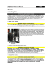
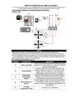
RigMaster Power Service and Repair Manual Document #S801009 S8.0 Engine Electrical and Control System (General Information) The RigMaster APU electronic control system consists of two main components, a Cabin Controller (CC) and a Power Module (PM), which are linked by an 8 wire, category 5e communication cable with (RJ-45) connectors at each end. The Cabin Controller is the interface sending user commands to the Power Module. The Power Module provides control intelligence to the unit by monitoring inputs and regulating outputs based on commands sent from the Cabin Controller and various engine sending units. There are 2 versions of the RigMaster Power Module and Cabin Controller. The RP7-901 controller uses the Yellow faced RP7-902 power module. The RP50-201 controller uses the grey faced RP50-202 power module. You cannot combine the old and new components as the software in each power module is written for the functionality of the cabin controller. RP7-901 Version 1 Controller RP7-902 Version 1 Power Module RP50-201 Version 2 Controller RP50-202 Version 2 Power Module The cabin controller displays a number of error messages intended to act as diagnostic aids. These error messages do not indicate a specific problem, but rather provide general guidelines to aid in the troubleshooting process. (See S8.2 for a list of trouble shooting codes) Note The cabin controller does not have any memory function to store codes. Once a button has been pushed the code will be cleared. Ensure you have the code written down prior to pressing a button as there is no way to retrieve the code once cleared. Copyright RigMaster Power by Mobile Thermo Systems Inc. 09-28-09 RigMaster Power Service and Repair Manual Document #S811009 S8.1 Operation of the Electronic Control System Version 1 1 2 6 3 4 CONTROL PANEL-FIGURE 8-1 5 1 The LCD MODULE DISPLAY is used to prompt the user through each operating mode. The display will back light when the user touches any key and will turn off if not used for 30 seconds. 2 The GREEN STATUS light indicates the cabin controller is active and functional. The RED STATUS light indicates a system problem and an error message will appear on the display. (Refer to error message listing of this supplement). NOTE: No STATUS light indicates the system is inactive (OFF). 3 The POWER key controls whether the module is active. Pushing the Power key will turn on the LCD backlight and activate the menu display or will turn the system off. 4 The MODE key is used to activate the different operational modes and will back you out of the menu mode to the main display. 5 The ARROW keys are used to locate the desired data and/or adjust those values. 6 The SELECT key enters the data and advances the program to the next menu step. NOTE: Pressing the select button will save the information inputted when entering operational data Copyright RigMaster Power by Mobile Thermo Systems Inc. 09-28-09 RigMaster Power Service and Repair Manual Document #S811009 OPERATION OF THE CABIN CONTROLLER Power On When the RigMaster system is off, the cabin controller enters the low power mode and becomes inactive, shutting off all non-critical functions. In low power mode the display shows: the day of the week and date on the top line and the time and total hours of operation on the bottom line. Pressing the POWER key will activate the normal mode turning the system on. The display will light and the status LED will become green. The display will show the day of the week and time on the top line and the system status (on/off) as well as the temperature setting on the bottom line. Pressing the MODE key again will activate the menu mode. The display will show SELECT on the top line and START SYSTEM on the bottom line. Set Time/Date NOTE: It is necessary to enter and date programming mode if the module has never been programmed or a different time zone is required. Press MODE key Press UP or DOWN key to find Set Time / Date mode on the display Press SELECT key Press UP or DOWN key to find Set Time Press SELECT key clock hour will start flashing Press UP or DOWN key to adjust clock hour Press SELECT key clock hour will stop flashing and clock minutes will start flashing Press UP or DOWN key to adjust clock minutes Press SELECT key clock minutes will stop flashing and am/pm will start flashing Press UP or DOWN key to change am/pm Press SELECT key to save settings and return to menu mode Press MODE key to back out of the menu To Set Date Press MODE key Press UP or DOWN key to find Set Time/Date mode on the display Press SELECT key Press UP or DOWN key to find Set Date mode Press SELECT key Month will start flashing Press UP or DOWN key to find the correct month Press SELECT key Month will stop flashing and calendar date will start flashing Press UP or DOWN key until correct date appears Press SELECT key to save settings and return to menu mode Copyright RigMaster Power by Mobile Thermo Systems Inc. 09-28-09 RigMaster Power Service and Repair Manual Document #S811009 Press MODE key to back out of the menu To Set Day Press MODE key. Press UP or DOWN key to find Set Time/Date mode on the display. Press SELECT key Press UP or DOWN key to find Set Day mode. Press SELECT key Press UP or DOWN key to find the correct day of the week. Press SELECT key to save settings and return to menu. Press MODE key to back out of the menu Set Alarm Clock Press MODE key Press UP or DOWN key to find Set Alarm Clock mode. Press SELECT key clock hour will start flashing Press UP or DOWN key to adjust clock hour Press SELECT key clock hour will stop flashing and clock minutes will start flashing Press UP or DOWN key to adjust clock minutes Press SELECT key clock minutes will stop flashing and am/pm will start flashing Press UP or DOWN key to change am/pm Press SELECT key on or off will display Press UP or DOWN key to change setting Press SELECT key to save changes and return to menu mode Press MODE key to back out of the menu Note: The Alarm symbol ‘*’will appear on the screen to indicate that the alarm is on. When the alarm is activated the SELECT button will cancel the alarm and remove the alarm symbol from the screen. If the alarm is not turned off manually it will ring for one minute and then “snooze” for four minutes before sounding again. Engine Start Press MODE key Start System will display Press SELECT key The control panel will display the status of the operation as it occurs: Starting System Glow Plugs and a 15 second countdown Cranking Engine Copyright RigMaster Power by Mobile Thermo Systems Inc. 09-28-09 RigMaster Power Service and Repair Manual Document #S811009 Please W ait Engine Running will display for 5 seconds and then return to the normal mode The normal mode will display System On Engine Stop Press MODE key. Stop System will display. Press SELECT The control panel will display the status of the operation as it occurs: Engine Running Engine Stopped The control panel after 5 seconds will return to normal mode Temperature Control Press MODE key. Press UP or DOWN key to find the Set Temperature mode Press SELECT key Press UP or DOWN keys to find desired temperature Press SELECT key to save setting Press MODE key to return to normal mode NOTE: Temperature control ranges from 65°F to 85°F. The system will remember the last set temperature when it is turned off Fan Speed Control Press MODE key. Press UP or DOWN key to find the Set Fan Speed mode Press SELECT key Press UP or DOWN key to desired fan setting Press SELECT key to save setting Press MODE key to return to menu NOTE: The system will remember the last fan setting after system is shutdown. To stop climate control the fan speed MUST be set to the off setting. During warmer months use the automatic on setting to improve air conditioner efficiency. During the cooler months use the automatic off setting to improve heater efficiency. Low Battery Alarm Copyright RigMaster Power by Mobile Thermo Systems Inc. 09-28-09 RigMaster Power Service and Repair Manual Document #S811009 When the truck battery voltage reaches 12.0 V +/- .2 Volts the low battery alarm will sound AUTOSTART CONTROL OPTION This feature can be purchased at an additional cost. AutoStart Date/Time Allows you to program the AutoStart to the exact date and time you need your RigMaster to start automatically up to seven days in advance. If you are setting this feature to heat or cool the bunk you MUST make sure your fan speed and temperature settings are programmed. This program has a run time of three hours and will override all other AutoStart features. Once the program is completed it will shut off and the last time/date will be stored. You will need to turn on this feature each time you use it. NOTE: If your RigMaster is running on another AutoStart program, e.g. Auto Temperature Control or Low Battery Start-up program and surpasses the time and date set for AutoStart then the APU will not start on this program. Automatic Temperature Control This control allows you to regulate the temperature in the bunk automatically providing additional fuel savings. Fan and temperature settings MUST be set in order to activate this control. The engine will NOT shut down if the fan setting is set to the off position. If you are setting the Auto-start Temp to heat the bunk, the APU will start at 6 degrees below the set temperature and run until set temperature is reached, then shut off. If you are setting the Auto-start Temp to cool the bunk, the APU will start at 6 degrees above the set temperature and run until set temperature is reached, then shut off. NOTE: Fan speed has to be set to low, medium, high, automatic off, or automatic on before the engine will shut down when using the AutoStart feature. The engine will not shut down if the fan setting is set to off. Low Battery Start Up This feature replaces the low battery alarm and automatically starts up the RigMaster to charge the truck batteries if they get below 12 volts ± .2 volts. The engine will shut down after 20 minutes of charging. The engine will then restart after four minutes if the truck batteries are still below 12 volts ± 0.2 volts. When the truck batteries fail to sustain voltage and the truck batteries drop below 11 .5V the RigMaster will shut down and a system charging error message will display on the cabin controller. Copyright RigMaster Power by Mobile Thermo Systems Inc. 09-28-09 RigMaster Power Service and Repair Manual Document #S811009 NOTE: Once the RigMaster starts on low battery AutoStart, it will not operate any system other than the engine, charging system, and the 110V generator regardless of fan speed and temperature settings. Programming AutoStart Code When you purchase the AutoStart feature you will be provided with a 4 character/digit code which must be first programmed in to the cabin controller Ensure the cabin controller is in low power mode. (Status light off) Press and hold the MODE key and SELECT key at the same time for 5 seconds. The display will show AutoStart code XXXX and the first character/digit will be flashing Press UP or DOWN key to locate the first digit/character in the code Press the SELECT key to accept the data and move to the next digit Continue entering the code in the above manner until all four characters have been selected. Once all four digits have been entered the system will accept the code and a message will display Code Ok AutoStart Code: ______________ Note: The AutoStart code will ONLY function on provided controller kit Programming AutoStart Press MODE key. Press UP or DOWN key to find the Set AutoStart mode Press SELECT key and Set Time AutoStart appears Press SELECT key and day of week starts flashing Press UP or DOWN key to adjust day of week Press SELECT key and day of week will stop flashing and clock hour will starts flashing Press UP or DOWN key to adjust clock hour Press SELECT key and clock hour will stop flashing and clock minutes will start flashing Press UP or DOWN key to adjust clock minutes Press SELECT key and clock minutes will stop flashing and am/pm will start flashing Press UP or DOWN key to adjust am/pm Press SELECT key and am/pm will stop flashing and on/off will start flashing Press UP or DOWN key to change on/off Press SELECT key to save settings and return to menu mode Press MODE key to return to normal mode Copyright RigMaster Power by Mobile Thermo Systems Inc. 09-28-09 RigMaster Power Service and Repair Manual Document #S811009 Note: Once you have set the program a # symbol will appear on the normal mode screen. If you touch any keys once this program is activated it will default to OFF. This control will run a continuous 3 hour program and then will default to OFF. You MUST set this program each time you use it. Set Auto Temperature Control Press MODE key. Press UP or DOWN key to find the Set AutoStart mode Press SELECT key and Set Time AutoStart appears Press UP or DOWN key to find the Set Auto Temperature mode Press SELECT key and on/off will start flashing Press UP or DOWN key to turn on/off Press SELECT key to save setting and return to menu mode Press MODE key to return to normal mode Note: This is a onetime program and will default to OFF. If you touch any keys once this program is activated it will default to OFF. You MUST set this program each time you use it. Set Auto Battery Control Press MODE key. Press UP or DOWN key to find the Set AutoStart mode Press SELECT key and Set Time AutoStart appears Press UP or DOWN key to find the Set Auto Battery Press SELECT key and on will display Press SELECT key to exit and return to the menu mode Press MODE key to return to normal mode Note: This setting can not be changed on cabin controller version 1.08 or higher, it is always set to ON. This setting can be changed on older cabin controller versions. Notes Copyright RigMaster Power by Mobile Thermo Systems Inc. 09-28-09 RigMaster Power Service and Repair Manual Document # S821009 S8.2 Operation of the Electronic Control System Version 2 To perform many of the procedures in this manual it is necessary to know how to use the electronic control system to start and stop the unit and confirm the operation of its systems after service and repair. The Cabin Controller consists of two sections: 1. LCD (Liquid Crystal Display) with basic control buttons. 2. Advanced control buttons The LCD and basic control buttons are always visible to the user. The advanced control buttons are concealed behind semi-circular cover. The controller also contains a LED indicator. When the LED is green, the system is active, if it Figure 8-2 glows red then the system is detecting a problem and an error message will scroll across the bottom of the LCD screen. The LED is turned off in low power mode. 1. Basic Controls and Functions Basic controls contain the following buttons: 1. Start system 2. Stop system 3. Up arrow (Red triangular button) 4. Down arrow (Blue triangular button) If the unit is in advanced mode, pressing any of the basic control buttons will return the unit to basic mode. Alternately, the control panel will return to basic mode after two minutes of inactivity. When the cabin controller displays the current temperature, pressing either the up or down button will show the set point temperature without changing it. Once the set point is indicated, pressing up or down buttons will adjust the set point. The new set point takes effect only when display is returned to show internal temperature. 2. Advanced Controls and Functions The advanced controls are as follows: 1. Power button controls whether the module is active. In inactive mode all system functions including engine start, climate control and AutoStart are disabled. You can still see the temperature reading, current time and use the alarm clock function. 2. Fan button is used to change fan setting. Pressing the button cycles between auto, high, med, low and off settings. 3. Clear button will take you back to the main screen without saving any information. 4. Clock button is used to set the time/date/day menu features. 5. Alarm button is used to set the alarm menu features. 6. AutoStart button is used to access and set AutoStart menu features. 7. Mode button is used to activate the different operational modes. Pressing the mode button will back you out of a menu mode, but does not save the information just entered. 8. Ext. Temp button will display the external temperature on the LCD when pressed. 9. Oprtg. Hour’s button will display the total hours of use. Copyright RigMaster Power by Mobile Thermo Systems Inc. 09-28-09 RigMaster Power Service and Repair Manual Document # S821009 Note The operating hours of the APU are recorded within the cabin controller. Replacing the cabin controller will reset the operating hours to zero. There is no means of transferring the operating hours from the old controller to the new controller. 10. Select button enters the data and advances the program to the next menu step. Pressing the select button will save the information when entering operational data. 11. Left scroll button (with symbol) 12. Right scroll button (with symbol) The left and right arrow buttons are used to locate the desired data and/or adjust those values. 3. Understanding the Cabin Controller LCD Display The Cabin Controller LCD has a white backlight that turns on each time a user presses a button and will remain on for 2 minutes after the last button that has been pushed. The backlight will turn red when there is an alarm condition. A fault code will be displayed if the unit shuts down or fails to start. The LCD displays 4 groups of information: 1. System information 2. Temperature information 3. Clock, day and alarm information 4. Alphanumeric display for additional information 1. System Information: SYSTEM ALARM symbol will flash if an alarm condition has occurred. The alphanumeric display along the bottom of the display screen will show more information about the alarm. Red status LED will be on. SYSTEM ON symbol will display if the unit is in ON mode. (Green status LED will be on. ENGINE RUNNING symbol will display when the engine is running. AUTOSTART symbol will display and flash if temperature AutoStart is enabled (when engine is off). If the engine has been started through AutoStart, this symbol is constantly on while the engine is running. HEATING symbol will display when the system is in heating mode. COOLING symbol will display when the system is in cooling mode. FAN AUTO, FAN HIGH, FAN MED, or FAN LOW symbol will display depending on which setting has been selected. Nothing will display in this area if the fan is set to off. 2. Temperature Information: This area indicates the internal (or external) temperature and can be programmed to display in either “Celsius” or “Fahrenheit” Internal temperature is shown if EXT TEMP and SET TEMP symbols are not illuminated. Pressing the Ext. Temp button will Copyright RigMaster Power by Mobile Thermo Systems Inc. 09-28-09 RigMaster Power Service and Repair Manual Document # S821009 momentarily display the outside temperature. After 5 seconds, the display will default back to showing the internal temperature. EXT TEMP symbol will flash when showing external temperature. After a few seconds the display returns to show internal temperature. SET TEMP symbol appears (and the numeric temperature value will flash) whenever adjusting temperature set point. A few seconds after adjusting the temperature, the display returns to show internal temperature. 3. Clock and Alarm: This is a 12:00 hour clock system with AM/PM symbols and 7 symbols indicating day of the week: MO, TU, WE, TH, FR, SA, SU. CLOCK symbol appears when the current time is showing. ALARM symbol appears to indicate that the alarm setting is showing. Pressing the alarm button allows you to set the alarm. The alarm symbol flashes when the alarm has been set. TIME AUTOSTART symbol appears if the display shows time AutoStart setting. It flashes if time AutoStart is set. 4. Additional Information/Message Area: This line is used to show extra information in the basic mode, error messages to provide interface when going through menus in advanced mode. Longer text lines are scrolled to the left on the display. Operation of the Cabin Controller (Functions) To Turn Power On Press the POWER button to activate the system. When the power switch is activated the LCD display will light and SYSTEM ON symbol will turn on (active mode). Press POWER button again for 2 seconds to switch the unit back to low power mode. Engine Start Press START button. The control panel will display the status of the operation as it occurs: Glow Plug and a countdown will display on the screen. Once the countdown is complete the display will read Cranking as the APU starts up and the ENGINE RUNNING symbol will blink. Once started the control will display Engine Running for 5 seconds (and ENGINE RUNNING symbol will turn on). Copyright RigMaster Power by Mobile Thermo Systems Inc. 09-28-09 RigMaster Power Service and Repair Manual Document # S821009 Engine Stop Press STOP button. The screen will initially display Stopping and then change to Stopped once the operation is complete. The Engine Running symbol will turn off. Temperature Control Press UP or DOWN (red/blue) buttons to adjust temperature set point on the display. When editing the set point, the LCD display will show the set point instead of internal cabin temperature. The set point is stored without a need to press any other buttons. NOTE The manual temperature control ranges from 59ºF-90ºF (15ºC to 32ºC). The system will remember the last set temperature when the APU is turned on. If the system is already running, the change will take effect a few seconds after the last UP or DOWN key is pressed and the display will switch back from set point to internal cabin temperature. Clock & Date Set Up It is necessary to enter the time and date programming mode if the module has never been programmed or a different time zone is required. (SET symbol is flashing and CLOCK symbol is turned on during clock setup) Press CLOCK button: The display will read Set Clock. Press SELECT button to continue, MODE to exit. Clock hour will start flashing. Press LEFT or RIGHT scroll button to adjust Clock hour. Press SELECT button: Clock hour will stop flashing and Clock minutes will start flashing. Press LEFT or RIGHT scroll button to adjust Clock minutes. Press SELECT button: Clock minutes will stop flashing and am/pm will start flashing. Press LEFT or RIGHT scroll button to change. Press SELECT button: am/pm will stop flashing and day of week will start flashing. Press LEFT or RIGHT scroll button to change. Press SELECT button: day of week stop flashing and Month will start flashing. Press LEFT or RIGHT scroll button to change. Press SELECT button: Month stop flashing and Date will start flashing. Set Alarm Clock Press ALARM button: The display will read Set Alarm. Press SELECT button to continue, MODE to exit. Alarm Clock hour will start flashing. Press LEFT or RIGHT scroll button to adjust Alarm Clock hour. Press SELECT button: Alarm Clock hour will stop flashing and Alarm Clock minutes will start flashing. Press LEFT or RIGHT scroll button to adjust Alarm Clock minutes. Press SELECT button: Alarm Clock minutes will stop flashing and am/pm will start flashing. Press LEFT or RIGHT scroll button to change. Press SELECT button Press LEFT or RIGHT scroll button to turn Alarm clock on/off. Press SELECT button to save settings and return to menu or press MODE to return to menu without saving. When enabled, ALARM symbol is flashing. Fan Speed Control Copyright RigMaster Power by Mobile Thermo Systems Inc. 09-28-09 RigMaster Power Service and Repair Manual Document # S821009 Press FAN button to adjust fan speed: Press the FAN button to cycle through fan settings: AUTO OFF, AUTO ON, FAN LOW, FAN MEDIUM, FAN HIGH, FAN OFF. There is no need to press any other buttons to confirm. AUTO OFF is for heating efficiency during winter operation. AUTO ON is for air conditioning efficiency during summer operation. NOTE The air conditioning/heating system will only operate when the fan speed is in a setting other than OFF. To stop the operation of the air conditioning/heating system, the fan speed must be set to OFF. If the system was stopped by another method, the air conditioning/heating will start immediately when the system is restarted. 4. AutoStart Features and Operation AutoStart Time/Day Programming –allows you to program a day and time for the APU for the start automatically up to 7 days in advance. This feature will run for three hours and shut down. At the end of the AutoStart program the cabin controller will display the error code #10, “Run Timeout”; this is normal. Set Automatic Start Timer The user can adjust the time and day for the next timed AutoStart event. (SET symbol is flashing and TIME AUTOSTART symbol is turned on during alarm setup) Press AUTOSTART button: Time AutoStart will scroll across the screen. Press SELECT button to continue, MODE to exit. Press LEFT or RIGHT scroll button to adjust AutoStart hour as required. Press SELECT button Continue to set the AutoStart Minutes and am/pm as you would set the clock. Press SELECT button after each entry. Press LEFT or RIGHT scroll button to adjust AutoStart Day as required. Press SELECT button Press LEFT or RIGHT scroll button to locate On/Off. Press SELECT button to save settings or press MODE button to return to menu without saving. NOTE: When enabled, Time AutoStart symbol will be flashing. Automatic Temperature Control Start Up/Shut Down-will start and stop the APU to regulate the temperature giving you further fuel savings on extended absences from the cab. Set Automatic Temperature Start-Up Press AUTOSTART button twice: Temp AutoStart will scroll across the screen. Press SELECT button to continue, MODE to exit. Press LEFT or RIGHT scroll button to select mode of temperature control. Mode options include OFF, AUTO, HEAT or COOL only. Press SELECT button to continue, MODE to exit. Press LEFT or RIGHT scroll button to select AutoStart temperature set-point if HEAT or COOL have been selected. Press SELECT button to save settings or press MODE to return to menu without saving. NOTE The Automatic Start temperature range is between 32°F and 95°F (0°C and 77°C) Copyright RigMaster Power by Mobile Thermo Systems Inc. 09-28-09 RigMaster Power Service and Repair Manual Document # S821009 When enabled, the AutoStart symbol will flash. AutoStart temperature start-up will engage when the inside temperature is more than 5°F (3°C) lower or more than 5°F (3°C) higher than the temperature control setting (in auto mode). It also engages at least 1 minute after enabling AutoStart temperature. Low Battery Start Up-automatically starts up the APU to charge the truck battery if it gets low. This option is always enabled in active mode. The voltage sensitivity of the low battery AutoStart feature can be adjusted, however, this is a dealer programmable feature and must be performed at a RigMaster APU trained facility. Automatic Low Battery Start-Up Low Battery AutoStart does not require that it be set by the user in the same way as the time/date and temperature based AutoStart. All that is necessary to ensure that low battery AutoStart functions is to leave the APU engine OFF and the cabin controller powered on (active mode). However, the battery voltage that the AutoStart engages at can be reset by the dealer technician. The default voltage is 12 V +/- 0.2 V Version Display Press MODE button. Current version of the Power Module software will appear on the screen Press MODE or SELECT to return. Programming Options for Version 2 Controllers The technician has the ability to access the Version 2 controller’s programming and adjust the settings of various features. To access the programming options of the controller perform the following procedure: 1. Ensure the controller power is off. 2. Press the Select and “>” key together. The controller will ask for a 4 digit code. 3. Enter the code “Z123” to access the programming options. The programming options and defaults are as follows: Language Selection English (Default) – no other options available at this time. Display Temperature Degrees °F (default), or °C Copyright RigMaster Power by Mobile Thermo Systems Inc. 09-28-09 RigMaster Power Service and Repair Manual Document # S821009 Glow Plug Duration NOTE The default time for all RigMaster units up to the MTS models is 16 seconds. MTS models with the serial number T4-6 >5130 have their glow plug timing adjusted at the factory during testing. The glow plug times reflect the settings programmed in by RigMaster during testing and should be used when adjusting glow plug times. Extending glow plug times too long will prematurely burn out the glow plugs. <14°F (-10°C) = 16 seconds <50°F (10°C) = 16 seconds ≤85°F (30°C) = 8 seconds ≥85°F (30°C) = 4 seconds NOTE If the engine fails to start on the first try, the controller is programmed to default to 16 seconds for the glow plugs on the second and third attempt at starting. This is done to ensure that the pre-combustion chamber has adequate heat to initiate combustion in colder temperatures. Battery Voltage Range (AutoStart) NOTE The battery voltage range is set default to 12 volts. On MTS units >5130 the battery setting is raised to 12.3 volts to reduce the work load on the alternator. 0 = 12.0V Default The voltage lower limit is 11.5V = -5, the upper limit is 12.9V = 9. By increasing the number by 1 you increase the voltage range by .1 volts. Decreasing into the negative “-“will set the range below 12 volts. Keypad Backlight and Status LED Timeout On = Default, or Off. Copyright RigMaster Power by Mobile Thermo Systems Inc. 09-28-09 RigMaster Power Service and Repair Manual Document # S831009 S8.3 Electronic Control Operation and Fault Codes The RigMaster APU’s electronic control will display fault codes on the LCD display if the unit fails to start or shuts down. The following table contains fault codes and information on the cause and/or remedy. These fault codes will display one time only; if the code is cleared from the cabin controller, failure will have to reoccur for the code to be displayed again. CODE Error Code 1 Safety Cover Open Error Code 2 Low Oil Pressure REMEDY/CAUSE Engine cover of APU unit is open. APU will not start or run until the cover is closed Low oil pressure Error Code 3 Battery Low Voltage Low battery voltage Start system immediately Error Code 4 Engine Run Failure Engine started but did not run properly. Manual start attempts can occur. Error Code 5 Low Coolant/ Engine Overheated Engine will not run until temperature becomes normal or coolant level is at full. Error Code 6 Module Failure Error Code 7 Engine Start Failure Error Code 8 No Communication Error Error Code 9 Main Engine Running Error Code 10 Run Timeout Power Module is not responding. Engine did not start. Automatic start is disabled until operator presses select button. Communication between control panel and power module is lost. Engine will not run until communication is reestablished. Truck engine is running. APU will not run if the main engine is already running. The APU has shut down as the maximum run time has been exceeded in the AutoStart Time/Day Setting Copyright RigMaster Power by Mobile Thermo Systems Inc. REMEDY/COMMENT Cover not seated Damaged wiring Failed cover switch Switch out of adjustment Low oil level Wiring damaged Faulty switch Dirty Oil Filter Damaged or broken battery cables Excessive load on batteries Bad battery Faulty charging system Speed sensor adjustment Damaged speed sensor wiring Failed speed sensor Low coolant High Engine Temperature Failed Temperature or Coolant Level Switch Damaged Wiring Failed Power Module Bad glow plug relay Bad starter relay Failed glow plug Lack of fuel Communication Cable Damaged Poor Connectivity at the terminals Optional engine wire is connected to DC voltage supply at the power module Engine will only run 3 hours max when set on AutoStart Time/Day 09-28-09 RigMaster Power Service and Repair Manual Document # S831009 Error Code 11 Check Power Module Fuse Error Code 12 Battery Charging Failure Error Code 13 Battery Discharge Error Code 14 Check External Temperature Sensor Error Code 15 External Temp Disable Limit Error Code 16 Module Reset – Set Clock Very low battery voltage detected at the power module Battery voltage still low two minutes after cranking. Auto and manual starts can occur Alarm, system will enter low power mode. Auto and manual starts can not occur External temperature sensor disconnected from the power module Engine shut down since the external temperature is outside the programmed range. Set default to OFF from factory. Power to the cabin controller has been lost. Copyright RigMaster Power by Mobile Thermo Systems Inc. Check 20 Amp fuse at the power module (Located under the bunk on the HVAC unit) Faulty charging system Bad batteries Engine harness ground wires disconnected at the HVAC Bad batteries External Temperature Sensor Disconnected Connection loose or damaged The APU has been programmed not to start when the external temperature is outside a preprogrammed range. Reset clock 09-28-09 RigMaster Power Service and Repair Manual Document # S841009 S8.4 General Electrical System Information and Power Module Connections WARNING To perform service, maintenance and repairs you must disconnect the APU from its battery source. In the recommended installation configuration the APU shares the battery bank with the vehicles main engine. After disconnecting the battery cables, check the battery posts inside the APU engine cabinet to confirm there is no voltage to the auxiliary power unit (APU). The RigMaster APU electrical system is a 12 Volt DC system in which vehicle and APU electrical accessories are powered by the vehicles battery and in turn charged by the RigMaster APU alternator when the APU is running. General Electrical Troubleshooting 1. Ensure proper grounding of the RigMaster APU unit and the vehicles electrical system. 2. Check the RigMaster APU’s electrical connections including battery and vehicle connections; look for damaged wires, signs of corrosion and secure connections. 3. Check Fuses and Relays. (Starter and Glow plugs) 4. Verify that the correct voltage is present and continuity within the circuit. Harness Markings Figure 8-3 Figure 8-4 Power Module Connections The power module has several connection points that are individually labelled on the face of the module itself. Please read the following section for detailed information on the function of these terminals. The connection points are the same for both version 1 and version 2 power modules. J1- Main Power Input, Relay Outputs, Air Conditioning Control J3 J1 J2- Electronic Coolant Control, Blower Motor Control J4 J3- Cabin Control Power and Communication J4- Sensor Inputs J5- External Temperature Sensor J2 J5 Figure 8-5 Copyright RigMaster Power by Mobile Thermo Systems Inc. 09-28-09 RigMaster Power Service and Repair Manual Document # S841009 J1 Pins Main Power Input, Relay Outputs, Air Conditioning Control PIN # TYPE COLOR 1 OUTPUT White - Engine Run Solenoid 12V=ON, 0V=OFF (Max current 2A) 2 OUTPUT Green - A/C Clutch Control. 12V=ON, 0V=OFF. (Max current 4A) 3 Not In Use 4 POWER Black - Ground = 0V 5 POWER Red/Black Stripe - Positive Supply = 12V OUTPUT Brown - Glow Plug Relay 12V=ON, 0V=OFF (Max current 200 mA) 7 OUTPUT White - Block Heater Relay NOT USED 8 OUTPUT Yellow - Starter Relay 12V=ON, 0V=OFF (Max 200mA) 9 POWER Red- Positive Supply = 12V 10 POWER Red- Positive Supply = 12V 6 J1 ▼ 6 1 7 2 8 3 9 4 10 5 Note Pin output 7 is an option for a block heater for the engine and has a short white wire with a bullet connector. Copyright RigMaster Power by Mobile Thermo Systems Inc. 09-28-09 RigMaster Power Service and Repair Manual Document # S841009 J2 Pin Electronic Coolant Control, Blower Motor Control J2 PIN # TYPE 1 INPUT 2 OUTPUT 3 OUTPUT 4 5 POWER OUTPUT 6 OUTPUT 7 OUTPUT COLOR White-Feedback Signal from Water Valve. 12V= Valve Open, 0V= Valve Closed Black - Fan Control Signal Max Current 9A, 12V=ON, 0V=OFF (output is 50% duty cycle for low speed) White – Drive Motor to Open/Close Water Valve. (Max 2A) 12V=ON, 0V=OFF White – Water Valve Control Power =12V (Max 7A) Black - Fan Control Signal. Max Current 9A, 12V=ON, 0V=OFF (output is 75% duty cycle for medium speed) Black - Fan Control Signal. Max Current 9A, 12V=ON, 0V=OFF (output is 100% duty cycle for high speed) White- Drive Motor to Open/Close Water Valve. (Max 2A) 12V=ON, 0V=OFF 8 W1 W2 W3 W4 W5 W6 J2 ▼ 4 8 3 7 2 6 1 5 J2 TO WATER VALVE (W) Water Valve Connection Point NOT IN USE Power Module J2 Connection Point 4 3 2 1 5 6 7 8 Copyright RigMaster Power by Mobile Thermo Systems Inc. W1 W2 W3 W4 W5 W6 J2 PIN 7 J2 PIN 3 NOT USED J2 PIN 4 J2 PIN 1 TO GROUND 09-28-09 RigMaster Power Service and Repair Manual Document # S841009 J3 Pin Cabin Control Power and Communication J2 PIN # 1 2 3 4 5 6 7 8 TYPE INPUT/OUTPUT INPUT/OUTPUT COLOR (--) RS485 TRANSCIEVER (half duplex) (+) RS485 TRANSCIEVER (half duplex) J3 ▼ 8 7 POWER ==7V (LOGIC)7 6 POWER ==7V (LOGIC)7 5 GROUND ISOLATED GROUND 4 GROUND ISOLATED GROUND 3 NOT IN USE SHEILD NON-ISOLATED GROUND 2 1 Contact Side Note The communication cable is a 28 AWG/Category 5e cable which uses the RJ-45 modular connector. The transceiver is half duplex and powered by 7Vdc logic voltage. Copyright RigMaster Power by Mobile Thermo Systems Inc. 09-28-09 RigMaster Power Service and Repair Manual Document # S841009 J4-Pin Sensor Inputs J4 TYPE 1 INPUT 2 INPUT 3 3 INPUT 4 INPUT 5 INPUT 6 6 INPUT 7 7 INPUT 8 COLOR Green - Oil Pressure Sensor. 12V = Normal pressure, 0V = Low oil pressure Black - Safety Cover Sensor. 12V = Cover OFF 0V = Cover ON Green/Yellow - Pickup Speed Sensor 6 - 10V AC = Engine ON 0V AC = Engine OFF Red - Main Engine Running. (Optional) 12V = Main engine ON 0V = Main engine OFF Orange - Coolant Temperature Sensor. 12V normal temperature 0V = high temperature Blue/White – DPF (Optional) 0V = Normal backpressure 12 V Pulse = Level 1 Cleaning 12 V Constant = Level 2 Cleaning Red/Orange- Pickup Speed Sensor Ground J4 ▼ 5 1 6 6 2 7 7 3 3 8 4 Not in Use (Plugged) NOTE Main Engine Running is optional and is spliced to a truck ignition source near the HVAC box. The source is usually from the truck’s factory HVAC box. When 12V ignition is applied to this input on pin number 4 it will NOT allow the RigMaster to start in any mode while the truck’s main engine is running. NOTE The Speed Sensor uses pin 7 as a loop back signal ground Copyright RigMaster Power by Mobile Thermo Systems Inc. 09-28-09 RigMaster Power Service and Repair Manual Document # S841009 J5-Pin J5 External Temperature Sensor J3 TYPE 1 INPUT 2 INPUT 3 GROUND ▼ COLOR Red 1 Black 2 Black (heavier gage wire) 3 Temperature Sensor Figure 8-6 Note The sensor hangs through the cabin floor with the other electrical wiring. Copyright RigMaster Power by Mobile Thermo Systems Inc. 09-28-09 RigMaster Power Service and Repair Manual Document # S851009 S8.5 System Schematics Engine Sensor Schematic Copyright RigMaster Power by Mobile Thermo Systems Inc. 09-28-09 RigMaster Power Service and Repair Manual Document # S851009 Starting and Charging Schematic Copyright RigMaster Power by Mobile Thermo Systems Inc. 09-28-09 RigMaster Power Service and Repair Manual Document # S851009 Air Conditioning and Cooling Fan Schematic (MTS Model) Note On all RMP/RMC build RigMaster models, the fan relay takes power from the AC compressor clutch connection at the binary switch. This cycles the electric cooling fan with the AC clutch. Copyright RigMaster Power by Mobile Thermo Systems Inc. 09-28-09 RigMaster Power Service and Repair Manual Document # S861009 S8.6Testing the Electric Coolant Control To test the coolant control valve there is two things that need to be checked first. The male pins on the valve have to be straight. The connector on the J2 harness has 6 double pins holes. Make sure that the female connector pins on the J2 connector is plugged into the male pins on the valve. Note: Figure 8-7 shows the female connector. Make sure that the larger pin holes are facing to the outside of the water valve when making the connection. Outside edge of water valve Water Valve Harness Female Pins Water Valve Male Pins Figure 8-7 Pin Number 1 on the power module is an input. This pin will tell you if the valve is open or closed. Put you red lead from you multi meter in pin number one on the power module connector and put your black lead from you multi meter to ground (the heater box is a good ground). If you have 0volts +/- then the valve is closed. If you have 12.40volts +/- then the valve is open. CHECK TO MAKE SURE THE VALVE IS OPENING & CLOSING. Pin Number 2 on the power module is an output. This pin will have power when fan speed is LOW. To test the fan circuit, refer to section S8.7 Pin Number 3 on the power module is an output. This pin will tell you if there is power going to the valve. When the heat is needed the power module will send power to the valve to open it and let the coolant flow through the heater core. The voltage will be present when the valve is opening. When the valve is open the voltage will disappear. Pin Number 4 on the power module is a power wire. This pin has to provide power to the valve at all times (battery voltage +/-). Pin Number 5 on the power module is an output. This pin will have power when the fan speed is MEDUIM. To test the fan circuit, refer to section S8.7. Pin Number 6 on the power module is an output. This pin will have power when the fan speed is HIGH. To test the fan circuit, refer to section S8.7. Copyright RigMaster Power by Mobile Thermo Systems Inc. 09-28-09 RigMaster Power Service and Repair Manual Document # S861009 Water Valve Schematic Pin Number 7 on the power module is an output. This pin will tell you if there is power going to the valve. When the air conditioning is needed the power module will send power to the valve to close it & stop the coolant flow through the heater core. The voltage will be present when the valve is closing. When the valve is closed the voltage will disappear. Pin Number 8 on the power module is not used. Pin Number 6 on the water valve is the ground wire for the water valve. The heater box is a good ground source. Copyright RigMaster Power by Mobile Thermo Systems Inc. 09-28-09 RigMaster Power Service and Repair Manual Document # S871009 S8.7 Blower Motor Wiring The blower motor has a single black power input wire and a single blue neutral wire. (See figure 8-8) Power is supplied to the blower motor via three black power wires from the J2 connector. Each of the three power input wires will supply a different wattage to the blower motor which corresponds with one of three fan speed settings. (see connector outputs for J2, S8-4) Only one of the three power input wires should be hot at any given time. The neutral blower motor wire (blue) is connected to a source of ground. Figure 8-8 Figure 8-9 Blower Ground Connection Blower Power Connection Remove and Replace the Blower Motor Assembly 1. 2. 3. 4. Disconnect the power and neutral wires from the HVAC and J2 wiring harness. Remove the ducting from the blower motor. Remove the lid of the HVAC unit. (four hex head screws) The hex head screws that secure the blower assembly are accessed from within the HVAC unit. 5. Remove the fan assembly. 6. Reinstallation if the reverse of removal. Copyright RigMaster Power by Mobile Thermo Systems Inc. 09-28-09 RigMaster Power Service and Repair Manual Document # S881009 S8.8 Alternator Charging The RigMaster APU is equipped with an automotive style alternator that has a built in regulator. NOTE Check the condition and charge of the truck batteries prior to testing the alternator’s output. Weak or discharged batteries will affect alternator output. Ensure all the truck’s batteries are fully charged and in good condition. Replace any failed batteries first. NOTE It is recommended that dielectric grease be used on electrical connections. Figure 8-1 CHARGING SYSTEM DIAGNOSTIC PROCEDURE SYMPTOM Batteries not Charging PROBABLE CAUSE 1. Loose or broken belt. 2. Damaged or loose battery connection. 3. Poor battery condition. 4. Faulty alternator. 1. Faulty alternator. Batteries Overcharging REMEDY/COMMENT 1. Tighten or replace belt. 2. Inspect and/or replace battery connections. 3. Test batteries. 4. Check voltage at alternator field coil wire and truck batteries. 1. Check alternator output. (.2 V above Battery voltage) 1. Check drive belt tension, ensure the alternator mounting bolts and adjusting belts are tight Copyright RigMaster Power by Mobile Thermo Systems Inc. 09-28-09 RigMaster Power Service and Repair Manual Document # S881009 Belt Tension Chart Initial Belt Tension ¹ Used Belt Tension ² 90 to 110 lbs (400 to489 N) 60 to 80 lbs (267 to 356 N) 1. 2. Initial belt tension refers to new belt Used belt tension refers to a belt that has been in operation for 30 minutes or more 2. Check the positive and negative posts are in good condition and that all wiring connections are secure. 3. Check the positive cable between the alternator and the starter for a loose or damaged cable. 4. Before running the system, ensure the regulator power supply (yellow or white wire) has approximately 12 VDC when system is on. 5. With the unit running check the output at the battery. The battery reading should be approximately 13.0 V DC to 14.0 V DC. Copyright RigMaster Power by Mobile Thermo Systems Inc. 09-28-09 RigMaster Power Service and Repair Manual Document # S891009 S8.9 Sensors, Switches and Sending Units Flywheel Speed Sensor (RP7-103) It sends an alternating current signal proportional to the engine RPM that indicates the engine is running at its proper speed (above 800 RPM). The RigMaster APU will not operate if the speed sensor is disconnected, faulty or disabled. Figure 9-12 Note The speed sensors can become caked with belt dust and other debris, causing the sensor to fail. TEST Resistance Gap from Flywheel Voltage Output SPEC 625 Ω ±75 0.015” 8 V AC ± 2V Speed Sensor NOTE This resistance test can be done at the power module through pins 3 and 7 on the J4 connector to ensure continuity in the wiring from the power module to the speed sensor. Oil Pressure Switch (Perkins 185246060/Caterpillar 153-6617) The power module sends a signal to the oil pressure sensor from the J4 connector. When low oil pressure is detected, the oil pressure switch closes and grounds the signal to the engine. Voltage at Switch Battery Voltage 0 Volts Condition Normal Oil Pressure Low Oil Pressure The oil pressure switch on the Perkins 400 Series engine screws into the engine block at the location shown in figure 9-13. On the Perkins 100 Series engine the oil pressure sensor screws in to the cylinder head near the injectors shown in figure 9-14. After reinstalling the switch it should be tightened to 13.3 ft.-lbs. Ensure that thread sealant is used to prevent leaks. High Temperature Switch (Perkins 385720101/Caterpillar 176-7705) The power module sends a signal to the high coolant temperature sensor from the J4 connector. When high engine temperature is detected (230° F, switch closes and grounds the signal to the engine. Voltage at Switch Battery Voltage 0 Volts Condition Normal Temperature High Temperature Copyright RigMaster Power by Mobile Thermo Systems Inc. 09-28-09 RigMaster Power Service and Repair Manual Document # S891009 The high engine temperature switch screws into the water pump at the location shown in figure 9-13. After reinstalling the switch it should be tightened to 20 ft.-lbs. Ensure that thread sealant is used to prevent leaks. Figure 9-13 Oil Pressure Switch Coolant High Temperature Switch Perkins 400 Series Figure 9-14 Fuel Injectors Oil Pressure Switch Perkins 100 Series NOTE Ensure that there is a rubber boot over the each switch to prevent corrosion and exposure to moisture which may cause the switches to malfunction. The use of dielectric grease is highly recommended at these points of connection. Safety Cover Switch (RP7-021) When the engine cover is in place the safety cover switch is closed and the signal travels to ground. 0 volts will be at the power module J4 pin-2 when the cover is closed. Battery voltage will be at J4 pin-2 when the door is open. Copyright RigMaster Power by Mobile Thermo Systems Inc. 09-28-09 RigMaster Power Service and Repair Manual Document # S891009 Safety Cover Switch Figure 9-15 Low Coolant Sensor (RP5-1005) The low coolant sensor has a 30 second delay, so if coolant levels remain low for greater than 30 seconds the APU will shut down. The low coolant sensor is connected to the same circuit as the high coolant temperature sensor. If low coolant and/or high temperatures are sensed the unit engine will shut down and display a fault code on the cabin controller. 12 Volts normal volume, 0Volts Low Coolant volume. Surge Tank Assembly Overflow Reservoir (RP5-1002-AL) Low Coolant Sensor (RP5-1005) Figure 9-16 NOTE The aluminum coolant overflow tank RP5-1002-AL replaces the plastic overflow tank RP5-1002 Copyright RigMaster Power by Mobile Thermo Systems Inc. 09-28-09 RigMaster Power Service and Repair Manual Document # S8101009 S8-10 Battery Fuse WARNING The following procedures present hazards which can result in injury or death. Only persons qualified to carry out electrical and mechanical servicing should undertake this work. A 100 Amp in-line DC fuse must be installed on the RigMaster APU’s positive (+) battery cable. The fuse assembly kit and individual part numbers are listed below: Description Fuse Kit (Includes fuse holder with fuse, 18" Cable) Fuse Holder with Fuse 100 Amp Fuse only 18” positive battery cable Part Number RP7-085 RP7-071 RP7-073 RP7-042 NOTE The RigMaster APU positive battery cable should be located on a separate battery than the negative cable. The RigMaster APU positive battery cable should also be on an independent post (i.e. there should be no other line or load terminals connected to the same stud as the RigMaster APU’s positive battery cable). Installation of the Battery Fuse Battery Fuse Hardware Fuse Housing (2) Nuts (2) Lock Washers Fuse Base 100 Amp Fuse Figure 8-10 1. Install the battery cables on the RigMaster APU engine compartment battery studs and route them to the battery box ensuring that the cables are protected from any hazards that may damage them. Figure 8-11 Copyright RigMaster Power by Mobile Thermo Systems Inc. 09-28-09 RigMaster Power Service and Repair Manual Document # S8101009 2. Once the cables reach the battery box, find a suitable location to mount the in-line fuse base. The fuse assembly must be located in an area free of hazards and firmly secured (mounting hardware not included). NOTE Ensure that the 18 inch battery cable will reach the positive battery terminal and the fuse assembly prior to mounting the fuse assembly. 3. Cut back any excess cable that connects the RigMaster APU to the fuse assembly and secure the 5/16” eye terminal. The use of shrink tube and dielectric grease on all points of connection is highly recommended. 4. Connect the fuse assembly to the positive battery terminal with the 18 inch positive battery cable prior to connecting the RigMaster APU’s negative terminal. 5. Check for battery voltage to the main unit terminal posts and at the power module. Copyright RigMaster Power by Mobile Thermo Systems Inc. 09-28-09


