1
Access Procedures
Chapter 3
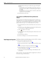
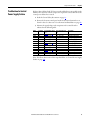
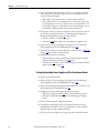
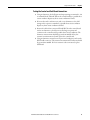
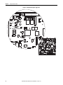
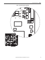
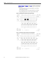
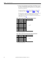
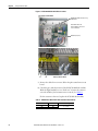
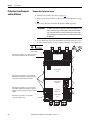
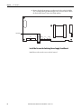
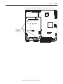
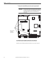
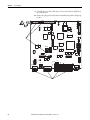
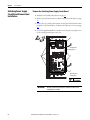
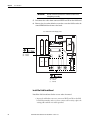
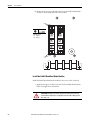
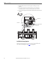
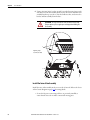
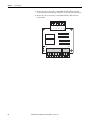
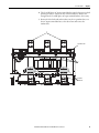
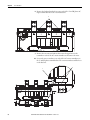
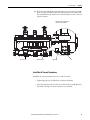
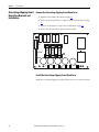
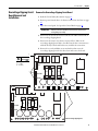
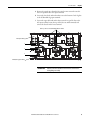
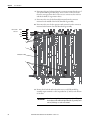
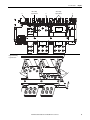
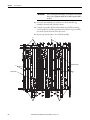
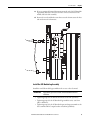
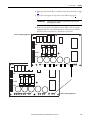
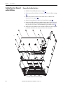
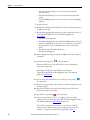
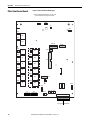
5. Disconnect the cables from connector XA and XUV on the switching
power supply board.
6. Remove the five screws that secure the board to the control EMI shield
and remove the board.
T15
Tightening torque:
1.0…1.2 N•m
(9…10.5 lb•in)
6
1D2
2
1
XA
16
F1
XSW1
1
4 1
1C2
XSW
XV
4
1
6
XUV
15
5
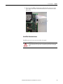
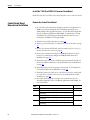
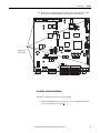
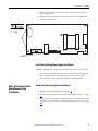
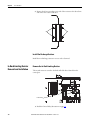
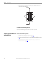
Install the Switching Power Supply Circuit Board
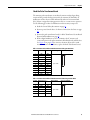
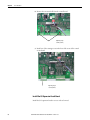
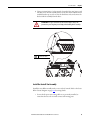
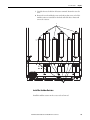
Install the switching power supply circuit board in the reverse order of removal.
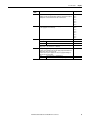
• Inspect the 16 Pin cable that connects to connector XA on the switching
power supply board for burn marks, cracks or a loose connector. If
necessary, replace the existing cable with the new cable provided.
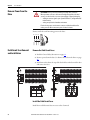
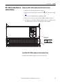
Pulse Transformer Circuit
Board Removal and
Installation
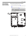
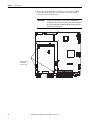
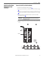
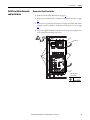
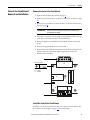
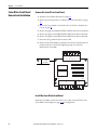
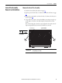
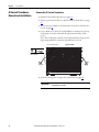
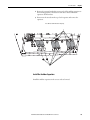
Remove the Pulse Transformer Circuit Board
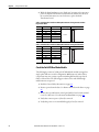
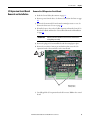
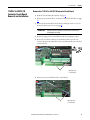
1. Read the General Safety Precautions on page 12.
2. Remove power from the drive. See Remove Power from the Drive on page
46.
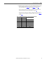
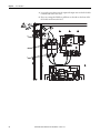
3. Remove the top control panel, bottom control panel, and I/O and control
terminal covers from the drive. See Remove the Protective Covers on page
48.
Rockwell Automation Publication 20P-TG004B-EN-P - October 2013
67