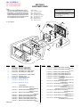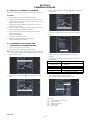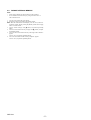
1
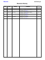
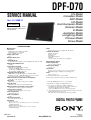
DPF-D70
US Model
Canadian Model
AEP Model
UK Model
East European Model
Russian Model
E Model
Australian Model
HongKong Model
Chinese Model
Korea Model
SERVICE MANUAL
Ver. 1.4 2008.11
Revised-4
Replace the previously issued
SERVICE MANUAL 9-852-290-14
with this Manual.
SPECIFICATIONS
■ Photo frame
LCD screen
LCD panel: 7 inches, TFT active matrix
Total number of dots: 1 152 000
(800 × 3 (RGB) × 480) dots
Display aspect ratio
15:9
Effective display area
7 inches
LCD backlight life
20 000 hours (before brightness of the backlight being reduced to half )
Maximum decodable file size
100 MB
Input/Output connectors
USB connector (miniB, full-speed) Slots
“Memory Stick PRO” slot
SD memory card/MMC/xD-Picture Card slot
CompactFlash card/Microdrive slot
Compatible image file formats
JPEG: DCF 2.0 compatible, Exif 2.21 compatible, JFIF*1
RAW (preview only*2): SRF, SR2, ARW (2.0 or lower version)
(Some image file formats are not compatible.)
Maximum number of pixels that can be displayed
8 000 (H) × 6 000 (V) pixels
File system
FAT12/16/32, sector size of 2 048 bytes or smaller
Image file name
DCF format, 256 characters, within 8th hierarchy
Maximum number of files that can be handled
9 999 files for a memory card/an external device
Internal memory capacity*3
256 MB (Approx. 500 images*4 can be saved.)
Power requirements
DC IN jack, DC 12V
Power consumption
7.7 W
Operating temperature
5 °C to 35 °C (41 °F to 95 °F)
Dimensions
[Without the stand]
Approx. 207 × 137 × 38.5 mm (8 1/4 × 5 1/2 × 1 9/16 inches)
(width/height/depth)
[With the stand spread out]
Approx. 207 × 137 × 125 mm (8 1/4 × 5 1/2 × 5 inches)
(width/height/depth)
Mass
Approx. 550 g (1 lb 3 oz) (excluding the AC adaptor)
Included accessories
• Digital photo frame
• Remote control
• AC adaptor
• Operating Instructions
• Warranty
(In some regions, the warranty is not supplied.)
■ Supplied AC adaptor
Power requirements
~100 V to 240 V, 50/60 Hz
Rated output voltage
12 V 1.2 A
Dimensions
Approx. 34 × 72 × 69 mm (1 3/8 × 2 7/8 × 2 3/4 inches)
(width/height/depth) (excluding the protruding parts)
Mass
Approx. 110 g (4 oz)
See the label of AC adaptor for more details.
Design and specifications are subject to change without notice.
*1: Baseline JPEG with 4:4:4, 4:2:2, or 4:2:0 format
*2: RAW files are displayed as thumbnail preview.
*3: The capacity is calculated as 1 MB is equivalent to
1 000 000 bytes. The actual capacity is reduced as files for
management and applications are included.
Approx. 200 MB can be used for your actual operation.
*4: Approximate number is shown when the images taken by 1 500 000
pixels equivalent camera are saved.
The value may vary depending on the shooting condition.
DPF-D70
9-852-290-15
Sony EMCS Co.
DIGITAL PHOTO FRAME
2008K0200-1
© 2008.11
Published by Kohda TEC
MAIN FEATURES
The Sony DPF-D70 is a digital photo frame for easily displaying
images taken with a digital camera or other device without using a
computer.
■ Support for various memory cards
Supports various memory cards used by digital cameras and other
devices, such as a “Memory Stick”, CompactFlash card, SD
memory card, and xD-Picture Card™.
Just insert a memory card removed from a digital camera or other
device, then you will be able to view the images immediately.
■ Various modes
The displayed image can be switched automatically as though
you are turning the pages of an album yourself.
You can select from various modes including just images, clock,
and calendar view.
You can also change playback settings such as the display order.
■ Various display functions
You can enjoy various view modes, such as displaying an analog
clock, digital clock or calendar. And the photo frame can display
images on single image display, index display, zoom in/zoom out
or fit to screen mode.
■ Automatic rotation of images
The photo frame automatically rotates images to their proper
orientation. Images are also automatically rotated when the photo
frame is set in either the portrait or landscape position.
■ Easy operation by remote control
■ Adding images to internal memory
The images you add to the album are saved to internal memory.
■ Exporting images
You can export images in the album to your memory card.
■ Connecting to a computer to exchange the images
SAFETY CHECK-OUT
After correcting the original service problem, perform the following
safety checks before releasing the set to the customer.
1.
2.
3.
4.
5.
6.
Check the area of your repair for unsoldered or poorly-soldered
connections. Check the entire board surface for solder splashes
and bridges.
Check the interboard wiring to ensure that no wires are
"pinched" or contact high-wattage resistors.
Look for unauthorized replacement parts, particularly
transistors, that were installed during a previous repair. Point
them out to the customer and recommend their replacement.
Look for parts which, through functioning, show obvious signs
of deterioration. Point them out to the customer and
recommend their replacement.
Check the B+ voltage to see it is at the values specified.
Flexible Circuit Board Repairing
• Keep the temperature of the soldering iron around 270˚C
during repairing.
• Do not touch the soldering iron on the same conductor of the
circuit board (within 3 times).
• Be careful not to apply force on the conductor when soldering
or unsoldering.
SAFETY-RELATED COMPONENT WARNING!!
COMPONENTS IDENTIFIED BY MARK 0 OR DOTTED LINE WITH
MARK 0 ON THE SCHEMATIC DIAGRAMS AND IN THE PARTS
LIST ARE CRITICAL TO SAFE OPERATION. REPLACE THESE
COMPONENTS WITH SONY PARTS WHOSE PART NUMBERS
APPEAR AS SHOWN IN THIS MANUAL OR IN SUPPLEMENTS
PUBLISHED BY SONY.
Unleaded solder
Boards requiring use of unleaded solder are printed with the leadfree mark (LF) indicating the solder contains no lead.
(Caution: Some printed circuit boards may not come printed with
the lead free mark due to their particular size.)
: LEAD FREE MARK
Unleaded solder has the following characteristics.
• Unleaded solder melts at a temperature about 40°C higher than
ordinary solder.
Ordinary soldering irons can be used but the iron tip has to be
applied to the solder joint for a slightly longer time.
Soldering irons using a temperature regulator should be set to
about 350°C.
Caution: The printed pattern (copper foil) may peel away if the
heated tip is applied for too long, so be careful!
• Strong viscosity
Unleaded solder is more viscous (sticky, less prone to flow) than
ordinary solder so use caution not to let solder bridges occur such
as on IC pins, etc.
• Usable with ordinary solder
It is best to use only unleaded solder but unleaded solder may
also be added to ordinary solder.
ATTENTION AU COMPOSANT AYANT RAPPORT
À LA SÉCURITÉ!
LES COMPOSANTS IDENTIFÉS PAR UNE MARQUE 0 SUR LES
DIAGRAMMES SCHÉMATIQUES ET LA LISTE DES PIÈCES SONT
CRITIQUES POUR LA SÉCURITÉ DE FONCTIONNEMENT. NE
REMPLACER CES COMPOSANTS QUE PAR DES PIÈSES SONY
DONT LES NUMÉROS SONT DONNÉS DANS CE MANUEL OU
DANS LES SUPPÉMENTS PUBLIÉS PAR SONY.
DPF-D70
—2—
Ver. 1.4 2008.11
The changed portions from
Ver. 1.3 are shown in blue.
SECTION 1
EXPLODED VIEWS
NOTE:
• -XX and -X mean standardized parts, so they
may have some difference from the original one.
• Items marked “∗” are not stocked since they are
seldom required for routine service. Some delay
should be anticipated when ordering these items.
• The mechanical parts with no reference number
in the exploded views are not supplied.
The components identified by mark 0 or
dotted line with mark 0 are critical for safety.
Replace only with part number specified.
• Abbreviation
AUS : Australian model
CH : Chinese model
CND : Canadian model
EE : East European model
HK : Hong Kong model
KR : Korea model
RUS : Russian model
TW : Taiwan model
Les composants identifiés par une marque
0 sont critiques pour la sécurité.
Ne les remplacer que par une pièce portant
le numéro spécifié.
ns: not supplied
ns
3
5
6
ns
ns
ns
5
ns
ns
ns
ns
ns
ns
ns
ns
ns
ns
ns
4
7
ns
ns
ns
1
ns
2
ns
Ref. No.
Part No.
Description
1
1
1
2
2
A-1546-161-A
A-1560-426-A
A-1560-428-A
A-1546-160-A
A-1560-425-A
CASE ASSY, FRONT (BLACK)
CASE ASSY, FRONT (RED)
CASE ASSY, FRONT (BROWN)
CASE BLOCK ASSY, FRONT (BLACK)
CASE BLOCK ASSY, FRONT (RED)
2
3
4
5
6
A-1560-427-A
A-1546-163-A
A-1546-162-B
3-080-206-41
4-115-829-01
CASE BLOCK ASSY, FRONT (BROWN)
CASE,ASSY, REAR
CASE BLOCK ASSY, REAR
SCREW, TAPPING, P2
SERVICE FFC (54 PIN)
7
4-115-828-01 SERVICE FFC (10 PIN)
Remarks
Ref. No.
0
0
< ACCESSORIES >
0
1-480-757-11 REMOTE COMMANDER (RMT-DPF1)
(REMOTE CONTROL)
3-300-258-11 MANUAL, INSTRUCTION (ENGLISH)
(EXCEPT CH, TW, KR)
3-300-258-21 MANUAL, INSTRUCTION (FRENCH)
(CND, AEP)
3-300-258-31 MANUAL, INSTRUCTION (GERMAN) (AEP)
3-300-258-41 MANUAL, INSTRUCTION (DUTCH) (AEP)
3-300-258-51 MANUAL, INSTRUCTION (ITALIAN) (AEP)
3-300-258-61 MANUAL, INSTRUCTION (SPANISH) (AEP, E)
3-300-258-71 MANUAL, INSTRUCTION (PORTUGUESE)
(AEP, E)
DPF-D70
0
0
0
0
-3-
Part No.
Description
Remarks
3-300-258-81 MANUAL, INSTRUCTION (RUSSIAN)
(EE, RUS)
3-300-258-91 MANUAL, INSTRUCTION (UKRAINIAN)
(EE, RUS)
3-300-259-11 MANUAL, INSTRUCTION (ARABIC) (E)
3-300-259-21 MANUAL, INSTRUCTION (PERSIAN) (E)
3-300-259-31 MANUAL, INSTRUCTION (KORIAN) (KR)
3-300-259-41 MANUAL, INSTRUCTION
(SIMPLIFIED CHINESE) (HK, CH)
3-300-259-51 MANUAL, INSTRUCTION
(TRADITIONAL CHINESE) (HK, TW)
3-876-557-01 SERVICE PARTS AC (AC-P12V1)
(AC ADAPTOR) (US, CND, TW)
3-876-699-01 SERVICE PARTS AC (AC-P12V2)
(AC ADAPTOR) (UK, HK)
3-876-700-01 SERVICE PARTS AC (AC-P12V3)
(AC ADAPTOR) (AEP, EE, RUS,
E(Central and South America, Middle East))
3-876-701-01 SERVICE PARTS AC (AC-P12V4)
(AC ADAPTOR) (AUS)
3-876-702-01 SERVICE PARTS AC (AC-P12V5)
(AC ADAPTOR) (CH)
3-876-703-01 SERVICE PARTS AC (AC-P12V6)
(AC ADAPTOR) (KR)
3-876-704-01 SERVICE PARTS AC (AC-P12V7)
(AC ADAPTOR) (E(Southeast Asia))
SECTION 2
FIRMWARE UPGRADE
2-1. METHOD OF UPGRADE OF FIRMWARE
4.
Choose "System Information” display with [m] button, and push the
ENTER button.
5.
Confirm it is a hoped firmware version, and push the [ENTER]
button.
6.
Confirm whether it is a display language that corresponds to
destination.
To change language, choose "Language settings" and push the
ENTER button.
Please executes when the enhance (upgrade of the firmware) is necessary.
Procedure
1.
2.
3.
4.
5.
6.
7.
Download the latest firmware from the ESI homepage.
Copy the firmware (downloaded and decompressed two files) onto
the root directory (most significant hierarchy) of the Memory Stick of
8MB or more empty capacity.
Install Memory Stick in the Memory Stick slot of this unit before
turning on the power supply.
Connect AC adaptor of accesessory with this unit and push the power
button while pushing the [VIEW MODE] button.
The screen becomes the confirmation display whether to do the
upgrade of the firmware.
Push the [ENTER] button.
The upgrade of the firmware starts.
The power supply cuts automatically when ending.
Remove Memory Stick from this unit.
2-2. CONFIRMATION OF VERSION AND
DESTINATION LANGUAGE SETTING
1. Turn on power pushing the power button.
2. Display the menu screen pushing the [MENU] button.
Note: When the demonstration mode display is in the screen, make it to
“Date/time setting” display pushing the [MENU] button after the [c]
button of remote control.
Destination
Except E33, EE,
RUS, CH, TW
E33
EE, RUS
CH
TW
3.
Choose "Various settings" with [m] button, and push the ENTER
button.
7.
Language
ENGLISH
SPANISH
RUSSIAN
SIMPLIFIED CHINESE
TRADITIONAL CHINESE
Choice language and push the ENTER button.
To erase the menu display, pushing the MENU button.
• Abbreviation
E33 : Central & South America model
CH : Chinese model
EE : East European model
RUS : Russian model
TW : Taiwan model
DPF-D70
-4-
2-3. FORMAT INTERNAL MEMORY
NOTE
•
•
All the images added to the internal memory will be deleted.
Do not format the internal memory by using connection to PC or
other external devices.
1. Turn on power pushing the power button.
2. Display the menu screen pushing the [MENU] button.
Note: When the demonstration mode display is in the screen, make it to
"Date/time setting" display pushing the [MENU] button after the [c]
button of remote control.
3. Choose "Various settings" with [m] button, and push the [ENTER]
button.
4. Choose "Format internal memory" display with [m] button, and push
the [ENTER] button.
5. The screen of "Format internal memory? All images will be deleted."
appears.
Choose "Yes", and push the [ENTER] button.
6. The screen of "Format internal memory completed." appears.
Choose "Yes", and push the [ENTER] button.
DPF-D70
-5-
Reverse
985229015.pdf
Revision History
Ver.
Date
1.0
1.1
2008.02
2008.03
Official Release
Revised-1
1.2
2008.04
Revised-2
1.3
2008.05
Revised-3
1.4
2008.11
Revised-4
DPF-D70
History
Contents
—
• Change of EXPLODED VIEWS
S.M. Revised: Page 3
• Change of EXPLODED VIEWS
S.M. Revised: Page 3
• Addition of red and brown models
S.M. Revised: Page 3
• Addition of two FFCs
S.M. Revised: Page 3
S.M. Rev.
issued
—
Yes
Yes
Yes
Yes