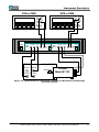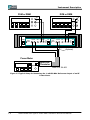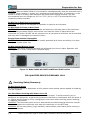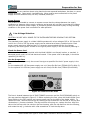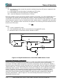
1
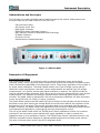
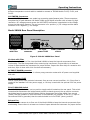
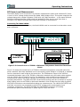
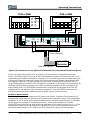
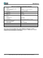
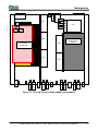
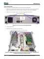
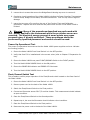
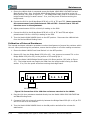
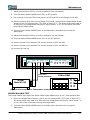
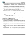
MODEL 1806A Dual Type IV Power Meter Instruction and Service Manual PN# 1806A-901-01 Publication Date: June 2010 REV. H TEGAM INC. MODEL 1806A DUAL TYPE IV POWER METER Instruction and Service Manual PN# 1806A-901-01 Publication Date: June 2010 REV. H NOTE: This user’s manual was as current as possible when this product was manufactured. However, products are constantly being updated and improved. Because of this, some differences may occur between the description in this manual and the product received. TEGAM is a manufacturer of electronic test and measurement equipment for metrology, calibration, and production test. We also provide repair, calibration, and other support services for a wide variety of test and measurement equipment including RF power sensor calibration systems, RF attenuation measurement systems, resistance standards, ratio transformers, arbitrary waveform generators, micro-ohmmeters, LCR meters, handheld temperature calibrators, thermometers, humidity and temperature control devices, and more. TEGAM also repairs and calibrates test and measurement equipment formerly manufactured by Electro-Scientific Industries (ESI), Gertsch, Keithley Instruments, Lucas Weinschel, and Pragmatic Instruments. A complete list can be viewed on our Product Service Directory at www.tegam.com For more information about TEGAM and our products, please visit our website at www.tegam.com: or contact one of our customer service representatives at [email protected] or 800-666-1010. Ten Tegam Way, Geneva, Ohio 44041 Telephone: (440) 466-6100 Fax: (440) 466-6110 E-mail: [email protected] b Model 1806A Dual Type IV Power Meter Instruction and Service Manual Table of Contents I Instrument Description ...................................................................................1-1 Abbreviations and Acronyms .................................................................... 1-2 Figure 1.1 Model 1806A .......................................................................... 1-2 Description of Equipment ........................................................................ 1-2 Functional Description ........................................................................ 1-2 Physical Description ........................................................................... 1-3 Specifications ................................................................................... 1-3 Table 1.1 Physical and Electrical Specifications ................................. 1-3 Additional Equipment .............................................................................. 1-4 Table 1.2 Additional Equipment Required .............................................. 1-4 Applications ........................................................................................... 1-4 Figure 1.2 Typical Setup for Calibrating a TEGAM (or Weinschel) Feedthrough Thermistor Mount ............................................. 1-5 Figure 1.3 Typical Setup for Measuring the 1 mW 50 MHz Reference Output of an RF Power Meter................................................ 1-6 II PREPARATION FOR USE ..................................................................................2-1 Unpacking & Inspection ........................................................................... 2-2 Mounting .............................................................................................. 2-2 Safety Information & Precautions ............................................................. 2-2 Terms in this Manual ......................................................................... 2-2 Terms as Marked on Equipment........................................................... 2-2 Symbols........................................................................................... 2-3 Grounding the Equipment ................................................................... 2-3 Danger Arising from the Loss of Ground ............................................... 2-3 Use in Proper Environment ................................................................. 2-3 Do Not Use in Explosive Environments.................................................. 2-4 Do Not Block Air Vents on Rear Panel ................................................... 2-4 Ensure Power Switch is Accessible ....................................................... 2-4 Do Not Operate without Covers ........................................................... 2-4 Figure 2.1 Model 1806A AC INPUT POWER and FUSE Location ...................... 2-4 Servicing Safety Summary ...................................................................... 2-4 Do not Service Alone ......................................................................... 2-4 Use Care when Servicing with Power On or Off ...................................... 2-4 Power Source ................................................................................... 2-5 Line Voltage Selection ............................................................................. 2-5 Check the Power Cord ........................................................................ 2-5 Use the Proper Fuse........................................................................... 2-5 Figure 2.2 Location of the Fuse....................................................... 2-5 III OPERATING INSTRUCTIONS ............................................................................3-1 1806A Front Panel Description ................................................................. 3-2 Figure 3.1 Model 1806A Front Panel ..................................................... 3-2 1806A Rear Panel Description .................................................................. 3-3 Figure 3.2 Model 1806A Rear Panel ...................................................... 3-3 RF Power Level Measurement ................................................................... 3-4 Connecting the Model 1806A ............................................................... 3-4 Figure 3.3 Connections for a TEGAM or Weinschel Temperature Controlled Thermistor Mount ........................................... 3-4 Model 1806A Dual Type IV Power Meter Instruction and Service Manual c Table of Contents Figure 3.4 Connections for an Agilent/HP Temperature Compensated Thermistor Mount .......................................................... 3-5 RF Power Measurement ...................................................................... 3-5 RF Power Level Measurement with an Agilent (HP) Thermistor Sensor .. 3-6 RF Power Level Measurement using the RVG .................................... 3-6 IV Theory of Operation ........................................................................................4-1 Principle of DC Substitution ..................................................................... 4-2 Precision Power Measurement .................................................................. 4-2 Figure 4.1 Simplified Schematic of the Model 1806A Bridge Circuit ........... 4-2 Self-Balancing Bridge Circuits.............................................................. 4-2 Power Measurements ......................................................................... 4-3 Figure 4.2 Simplified Schematic of the Model 1806A Heater Circuit ........... 4-4 Controlling Thermistor Temperature ..................................................... 4-4 Calculating Uncertainty ........................................................................... 4-5 Mismatch Uncertainty (MER) ................................................................ 4-5 Instrumentation Uncertainty (IE) ......................................................... 4-6 Table 4.1 Typical Instrumentation Error Analysis (IE) ......................... 4-6 VI Maintenance ....................................................................................................5-1 Table 5.1 List of Equipment Required for Calibration .................................... 5-2 Figure 5.1 Top View Layout of Model 1806A Subassemblies .......................... 5-3 Visual Inspection .................................................................................... 5-4 Figure 5.2 Location of Four Rear Panel Screws ....................................... 5-4 Figure 5.3 1806A Rear Panel Tilted Down and Top Cover Removed ........... 5-4 Power-Up Operational Test ...................................................................... 5-5 Float/Ground Switch Test ........................................................................ 5-5 Power Supply Tests ................................................................................ 5-6 Figure 5.4 Location of –OUT, T/C, and +OUT on PS1, PS2, and PS3 .......... 5-6 Figure 5.5 Location of –OUT, T/C, and +OUT on PS5 and PS6 .................. 5-7 Heater Circuit Functionality Test ............................................................... 5-8 Figure 5.6 Connection of the 1N914 Diode to the 1806A ......................... 5-8 Bridge Noise Test ................................................................................... 5-9 Figure 5.7 Location of Bridge Board Jumper .......................................... 5-9 Bridge Board Circuitry Test and Calibration ................................................ 5-9 Calibration of Internal Resistance ............................................................. 5-10 Figure 5.8 Connection of the 100 Ohm Resistance Standard to the 1806A . 5-10 Figure 5.9 Connection of a Temperature Controlled Thermistor Mount to the 1806A .......................................................................... 5-11 Bridge Balance Test ................................................................................ 5-11 RVG (Reference Voltage Generator) Test ................................................... 5-12 VI SERVICE INFORMATION ..................................................................................6-1 Warranty .............................................................................................. 6-2 Warranty Limitations .............................................................................. 6-2 Statement of Calibration ......................................................................... 6-2 Contact Information ............................................................................... 6-2 Preparation for Calibration or Repair Service .............................................. 6-3 Expedite Repair & Calibration Form ...................................................... 6-4 d Model 1806A Dual Type IV Power Meter Instruction and Service Manual Instrument Description INSTRUMENT DESCRIPTION PREPARATION FOR USE OPERATING INSTRUCTIONS THEORY OF OPERATION MAINTENANCE SERVICE INFORMATION Model 1806A Dual Type IV Power Meter Instruction and Service Manual 1-1 Instrument Description Abbreviations and Acronyms The following list contains all abbreviations used throughout this manual. Abbreviations and acronyms that are not listed conform to MIL-STD-12D. CW Continuous Wave SUT Sensor Under Test DVM Digital Voltmeter ESDS Electrostatic Discharge Sensitive NIST National Institute of Standards and Technology RF Radio Frequency DC Direct Current RVG Reference Voltage Generator Figure 1.1 Model 1806A Description Of Equipment Functional Description The TEGAM Model 1806A, in conjunction with an external thermistor mount and a digital voltmeter (DVM), forms a precision power measurement system that measures microwave power within the frequency bandwidth of the thermistor mount. The primary application of this system is for power sensor calibration. The Model 1806A contains two Type IV Bridge circuits and two thermistor mount temperature controllers. Power measurements are derived from DC voltage measurements, so a precise and accurate Digital Voltmeter is required. The 1806A includes an internal reference voltage generator (RVG) which can be used as a voltage offset for more precise measurements. This becomes increasingly important when measuring power levels below a milliwatt. The Model 1806A is designed for use with a temperature stabilized 200 Ohm thermistor mount and a DVM with a 6.5 digit, or higher, resolution. The Model 1806A contains two self-balancing Type IV Bridge circuits that pass current through a bolometer mount while sensing the voltage across the mount which defines the resistance of the bolometer at its DC terminals. This process eliminates lead errors associated with Wheatstone Bridges. Therefore, the Model 1806A suits applications such as power measurement and insertion loss measurement applications, requiring high accuracy and computer control. The role of the Model 1806A within the TEGAM Power Sensor Calibration System is to measure precisely RF and microwave power applied to RF power standards in order to transfer the calibration factor of one standard to another. The TEGAM Power Sensor Calibration System is an IEEE Bus compatible system designed to calibrate feedthrough and terminating power sensors. The ratio of the two power levels is the SUT’s calibration factor. 1-2 Model 1806A Dual Type IV Power Meter Instruction and Service Manual Instrument Description Physical Description Refer to Table 1-1 for the physical and electrical specifications of the Model 1806A. The Model 1806A front panel contains the INPUT POWER switch as well as two sets (one for each Bridge) of BIAS VOLTAGE, TEMP, and VOLTMETER connectors. The Model 1806A front panel also has two RVG switches for each bridge which enables the internal Reference Voltage Generator. Additionally, there are READY and ERROR indicators on the front panel. The rear panel contains the input power connector and fuse, FLOAT/GROUND switch, and vents for airflow. The Model 1806A is designed to sit on a bench but can be mounted in a 19” rack with rack mount kit RM-1825 (sold separately, call TEGAM for details). Specifications Table 1.1 lists the physical and electrical specifications of the Model 1806A. Power Range Table 1.1 Physical and Electrical Specifications 0.01 to 30 mW Substitution Bridge Accuracy ±0.003% Temperature Controller Bias Power Temperature Sensitivity Ambient Temperature Dynamic Range Mount Warm-Up Time Mount Internal Temperature Loop Gain Open Loop Frequency Response Warm-Up Drive (saturated) Indicator 2 µW/°C per hour +12 to +32C (+54 to +90F) 2 hours nominal Approximately +60°C (+140°F) 80 dB minimum 0.1 Hz 8-10 V @ 200 mA minimum Green LED Reference Voltage Generator 2.5 VDC ±1 mV Environmental Operating Temperature Storage Temperature Humidity Altitude +12 to +32C (+54 to +90F) -40 to +75C (-40 to +167F) Less than 80% RH, non-condensing Sea level to 2000 meters Connectors BIAS VOLTAGE TEMP VOLTMETER Binding posts, 0.75” spacing for banana plugs 4-pin mini-microphone Binding posts, 0.75” spacing for banana plugs Power Requirements 12 Watts, 50 to 400 Hz, 95 to 125 Vac standard or 210 to 250 Vac with a factory installed option Weight 20 lbs (9 kg) Physical Dimensions Height Width Depth 3.5 in (89 mm) 18 in (457 mm) 15.4 in (391 mm) Model 1806A Dual Type IV Power Meter Instruction and Service Manual 1-3 Instrument Description Additional equipment Table 1.2 lists the additional equipment required to measure RF power with the Model 1806A. The description for each piece of equipment listed states the minimum recommended requirements for that piece of equipment. There may be many models that meet the minimum requirements; it is up to the operator to select the specific model. Measurement uncertainty will vary depending on the additional equipment used. Please refer to the specifications for the particular model number to get that information. Table 1.2 Additional Equipment Required Thermistor RF Power Sensor 200 Ohm nominal resistance value. Temperature controlled models manufactured by TEGAM/Weinschel or temperature compensated models manufactured by Agilent/HP (with cable P/N 138-652). Digital Volt Meter (DVM) DC Volts, 10 V range, 6½-digit minimum. Lower resolution and range can be used with the RVG feature. APPLICATIONS The TEGAM Model 1806A Dual Type IV Power Meter is designed for measuring RF power. While this instrument is not designed for remote programming, the process of measuring RF power can be automated if the additional equipment used can be remotely programmed. Figures 1.2 and 1.3 show some typical applications for the 1806A. The 1806A and a 200 Ohm thermistor mount can be used for any application where average RF power level measurements need to be precisely made. 1-4 Model 1806A Dual Type IV Power Meter Instruction and Service Manual Instrument Description DVM or DMM DVM or DMM V+ V+ V- V- TEGAM BRIDGE A POWER I READY ERROR Dual Type IV Power Meter BIAS VOLTAGE BRIDGE B TEMP O TEGAM VOLTMETER ON TEST OFF RVG BIAS VOLTAGE TEMP VOLTMETER ON TEST OFF RVG Model F11XX RF IN TEMP IN SENSOR BIAS VOLTAGE READY ERROR Model 1806A TEGAM Model M11XX Figure 1.2 Typical Setup for Calibrating a TEGAM (or Weinschel) Feedthrough Thermistor Mount Model 1806A Dual Type IV Power Meter Instruction and Service Manual 1-5 Instrument Description DVM or DMM DVM or DMM V+ V+ V- V- TEGAM BRIDGE A POWER I READY ERROR Dual Type IV Power Meter BIAS VOLTAGE BRIDGE B TEMP O VOLTMETER ON TEST OFF RVG READY ERROR BIAS VOLTAGE TEMP Model 1806A VOLTMETER ON TEST OFF RVG VCOMP (Optional) VRF Power Meter Power Reference Agilent/HP Thermistor Cable P/N 138-652 Figure 1.3 Typical Setup for Measuring the 1 mW 50 MHz Reference Output of an RF Power Meter 1-6 Model 1806A Dual Type IV Power Meter Instruction and Service Manual Preparation for Use INSTRUMENT DESCRIPTION PREPARATION FOR USE OPERATING INSTRUCTIONS THEORY OF OPERATION MAINTENANCE SERVICE INFORMATION Model 1806A Dual Type IV Power Meter Instruction and Service Manual 2-1 Preparation for Use Unpacking & Inspection: Each 1806A is put through a series of electrical and mechanical inspections before shipment to the customer. Upon receipt of your instrument unpack all of the items from the shipping carton and inspect for any damage that may have occurred during transit. Report any damaged items to the shipping agent. Retain and use the original packing material for reshipment if necessary. Upon Receipt, inspect the carton for the following items: Model 1806A Dual Type IV Power Meter Model 1806A Operating and Service Manual (CD) Calibration Certificate Heater Cable (X2) Heater Cable (X2) Mount Bias Cable (X2) Power Cord P/N SYSIIB-840-01 P/N P/N P/N P/N CA-10-48 CA-11-48 138-526 As Required Mounting The Model 1806A is shipped with four feet mounted to the bottom cover. When the Model 1806A is placed on a bench or table, these feet support the instrument. The Model 1806A can also be rack mounted in a standard 19” rack using the optional rack adapter kit RM-1825. ! Safety Information & Precautions: The following safety information applies to both operation and service personnel. Safety precautions and warnings may be found throughout this instruction manual and the equipment. These warnings may be in the form of a symbol or a written statement. Below is a summary of these precautions. Terms in This Manual: CAUTION statements identify conditions or practices that could result in damage to the equipment or other property. WARNING statements identify conditions or practices that could result in personal injury or loss of life. Terms as Marked on Equipment: CAUTION indicates a personal injury hazard not immediately accessible as one reads the marking, or a hazard to property including the equipment itself. DANGER indicates a personal injury hazard immediately accessible as one reads the marking. 2-2 Model 1806A Dual Type IV Power Meter Instruction and Service Manual Preparation for Use Symbols: As Marked in This Manual: ! This symbol denotes where precautionary information may be found. As Marked on Equipment: ! CAUTION – Risk of Danger DANGER – Risk of Electric Shock Earth Ground Terminal l On O Off Frame or Chassis Terminal Earth Ground Terminal Alternating Current Grounding the Equipment This product is grounded through the grounding conductor of the power cord. WARNING: To avoid electrical shock or other potential safety hazards, plug the power cord into a properly wired receptacle before using this instrument. The proper grounding of this instrument is essential for safety and optimizing instrument operation. Danger Arising from Loss of Ground WARNING: If the connection to ground is lost or compromised, a floating potential could develop in the instrument. Under these conditions all accessible parts, including insulating parts such as keypads and buttons could develop a hazardous voltage and put the user at risk. ! Use in Proper Environment Normal calibration laboratory practice dictates that the environment should be closely controlled. This will minimize errors introduced by temperature and humidity changes. A nominal temperature of +23°C (+73.4°F) provides a good working condition. A tolerance of ±1°C gives allowable temperature spread. Controlled temperatures also stabilize the aging process of the standards. CAUTION: The Model 1806A has a specified ambient temperature range of +12° to +32°C (+54° to +90°F). Operating beyond these limits can affect the accuracy of the instruments and damage internal circuitry. Model 1806A Dual Type IV Power Meter Instruction and Service Manual 2-3 Preparation for Use CAUTION: When the Model 1806A is to be stored for extended periods, pack the instrument into a container. Place container in a clean, dry, temperature-controlled location. If instrument is to be stored in excess of 90 days, place desiccant with items before sealing container. The safe environmental limits for storage are -40° to +75°C (-40° to +167°F) at less than 80% noncondensing relative humidity. Do Not Use in Explosive Environments CAUTION: The 1806A is not designed for operation in explosive environments. Do Not Block Air Vents on Rear Panel CAUTION: The Model 1806A has an air intake and exhaust on the back panel of the instrument. When installing the Model 1806A, ensure there is at least two inches of space behind the instrument for airflow. DO NOT set the instrument on its rear panel as its airflow will be restricted and may result in damage to the internal circuitry. Ensure Power Switch is Accessible CAUTION: Ensure that the POWER switch is easily accessible at all times and nothing is in place that would impede proper use. Do Not Operate Without Covers WARNING: This device should be operated with all panels and covers in place. Operation with missing panels or covers could result in personal injury. Figure 2.1 Model 1806A AC INPUT POWER and FUSE location FOR QUALIFIED SERVICE PERSONNEL ONLY ! Servicing Safety Summary: Do Not Service Alone Do not perform service or adjustment on this product unless another person capable of rendering first aid is present. Use Care When Servicing with Power On or Off Dangerous voltages may exist at several points in this product. To avoid personal injury or damage to this equipment, avoid touching exposed connections or components while the power is on. Assure that the power is off by unplugging the instrument when removing panels, soldering, or replacing components. WARNING: The instrument power source is electronically controlled meaning that there is power present throughout the instrument even when the instrument is in the OFF state. WARNING: Do not wear jewelry (rings, bracelets, metal watches, neck chains) while working on exposed equipment. 2-4 Model 1806A Dual Type IV Power Meter Instruction and Service Manual Preparation for Use WARNING: Be very cautious about using hand tools near exposed backplanes, bus bars, or power supply terminals. Use properly insulated tools. When making test connections to the power supply terminals and bus bars; use only insulated probe tips. Power Source This product is intended to connect to a power source that the voltage between the supply conductors or between either supply conductor and ground will not apply more than the voltage rating for the particular power supply. A protective ground connection by way of the grounding conductor in the power cord is essential for safe operation. ! Line Voltage Selection: CAUTION: DO NOT APPLY POWER TO THE INSTRUMENT BEFORE READING THIS SECTION: The standard power supply in a Model 1806A operates with a line voltage of 95 to 125 Vac at 50 to 400 Hz. A 210 to 250 Vac power supply can be ordered as a factory installed option. Each power supply requires a different fuse. It is strongly recommended that the line voltage, frequency, and fuse type be verified for the type of power supply in the unit before powering it. Check the Power Cord Make sure the power cord supplied with the Model 1806A is not frayed, broken, or cracked. A damaged power cord is a fire and electrical hazard. If the power cord is damaged, it should be replaced (P/N 068-21). Use the Proper Fuse To avoid fire hazard, use only the correct fuse type as specified for the AC power supply in the unit. For the standard 95-125 Vac power supply use a 1.6 Amp Slo-Blo fuse (TEGAM P/N FU-1804-3). For the optional 210-250 Vac power supply use a 0.8 Amp Slo-Blo fuse (TEGAM P/N 430008). AC INPUT POWER FUSEGROUND FLOAT Figure 2.2 Location of the FUSE The fuse is located between the AC INPUT POWER connector and the FLOAT/GROUND switch on the rear panel as depicted in Figure 2.2. Before replacing the fuse, place the Model 1806A Front Panel Switch to the OFF position and remove power cord on the back of the Model 1806A. To replace the fuse, remove the fuse cap by inserting a flat screwdriver into the slot of the cap and rotate about ¼ counter-clockwise. The cap and fuse will spring out; replace the fuse. Align the tab on the fuse cap with the notch on the fuse housing, push the cap and fuse into the housing, and rotate the cap ¼ clockwise with a flat screwdriver to lock the cap down. Model 1806A Dual Type IV Power Meter Instruction and Service Manual 2-5 Operating Instructions INSTRUMENT DESCRIPTION PREPARATION FOR USE OPERATING INSTRUCTIONS THEORY OF OPERATION MAINTENANCE SERVICE INFORMATION Model 1806A Dual Type IV Power Meter Instruction and Service Manual 3-1 Operating Instructions Model 1806A Front Panel Description POWER ON ERROR RVG Indicator Indicator Switch POWER READY Switch Indicator TEMP BIAS VOLTAGE Connector Connectors VOLTMETER Connectors Figure 3.1 Model 1806A Front Panel POWER Switch The POWER switch switches the power input to the instrument on and off. This switch has a builtin indicator that is illuminated when power is on. See POWER ON indicator. POWER ON Indicator The POWER ON indicator illuminates when instrument power is on. It is built into the POWER switch. READY Indicator The READY indicator is a green LED that illuminates when the RF power standard has reached its internal operating temperature of approximately 60°C. Allow two hours for the power standard to reach this temperature and ensure the READY indicator stays illuminated during RF power sensor calibrations. ERROR Indicator The ERROR indicator is a red LED that illuminates for any condition preventing the Type IV Bridge circuit from balancing (i.e. an open or short on the BIAS VOLTAGE terminals). When the ERROR indicator becomes illuminated, stop any calibration and contact TEGAM for assistance. RVG Switch The RVG (Reference Voltage Generator) is a three position switch that is used to turn the RVG ON and OFF. The TEST position allows the user to measure the RVG voltage directly. BIAS VOLTAGE Connectors The Bias Voltage connectors are spade-lug connecting posts/banana jacks. These connectors complete the DC path between the 1806A Type IV Bridge and the thermistor element. The 1806A is designed for use with 200 Ohm thermistors only. TEMPerature Connector 4 pin mini-microphone connector that is used to connect the heater control circuit to an internal heater found in TEGAM (and Weinschel) RF Power Transfer Standards. TEGAM RF Power Transfer Standards require at least two hours of warm-up time to reach their operating temperature. Two temperature control cables (P/N CA-10-48) are supplied with the Model 1806A, however a 3-2 Model 1806A Dual Type IV Power Meter Instruction and Service Manual Operating Instructions different temperature control cable is needed to connect to TEGAM Models F1125, F1130, and F1135. VOLTMETER Connectors The VOLTMETER Connectors are spade-lug connecting posts/banana jacks. These connectors complete the DC path between the Model 1806A and a digital voltmeter with at least 6½-digit resolution. DC voltage present across the VOLTMETER connectors is equivalent to the voltage across the thermistor element. The red connector is for positive (+) DC voltage and the black connector is for negative (-) DC voltage. Model 1806A Rear Panel Description AC INPUT POWER FUSEGROUND FLOAT Air Vent with Filter AC INPUT POWER connector AC input power FUSE FLOAT/GROUND switch Exhaust Fan Figure 3.2 Model 1806A Rear Panel Air Vent with Filter The Air Vent allows air to flow into the Model 1806A to keep the internal components from overheating. The filter keeps debris from entering the instrument. Ensure there is at least two inches of space behind the instrument for proper airflow. Inspect the filter daily for excessive dirt and dust; wipe it clean with a lint free cloth as necessary. AC INPUT POWER connector The AC INPUT POWER connector is a three prong connector mates with AC power cord supplied with unit. AC input power FUSE The AC input power FUSE protects instrument from an over-current condition. A 1.6 Amp fuse is used with the standard 110 Vac power supply, a 0.8 Amp is used with the optional 220 Vac power supply. FLOAT/GROUND Switch The FLOAT/GROUND Switch is a two position toggle switch located on the rear panel. This switch connects and disconnects the bridge board ground to chassis ground; the up position connects the bridge board to ground and the down position disconnects the bridge board from ground (floats). Normal operation is with the switch in the GROUND (up) position. If the LO (-) input of the external DVM is grounded, then the switch should be in the FLOAT (down) position. Exhaust Fan The Exhaust Fan causes air to flow out of the Model 1806A to keep the internal components from overheating. Ensure there is at least two inches of space behind the instrument for proper airflow. Model 1806A Dual Type IV Power Meter Instruction and Service Manual 3-3 Operating Instructions RF Power Level Measurement The Model 1806A is one component in a precision measurement system that measures RF power in terms of a DC voltage change across the Model 1806A bridge circuit. This system measures the voltage change with a digital voltmeter (DVM) with a 6.5 digit resolution – or the same DVM and Reference Voltage Generator (RVG) when the applied RF power level is small (less than a milliwatt). This section describes both these two methods of measurement. Connecting The Model 1806A Before any measurements are taken, the Model 1806A must be connected to a thermistor mount and a voltmeter. TEGAM BRIDGE A POWER I O READY ERROR Dual Type IV Power Meter BIAS VOLTAGE BRIDGE B TEMP VOLTMETER ON TEST OFF Heater Cable RVG READY ERROR BIAS VOLTAGE TEMP Model 1806A VOLTMETER ON TEST OFF RVG DVM or DMM V+ TEGAM Model M11XX V- Figure 3.3 Connections for a TEGAM or Weinschel Temperature Controlled Thermistor Mount Figure 3.3 shows the connections for a TEGAM or Weinschel temperature controlled thermistor power standard. One these standards can be connected to either Bridge A or Bridge B; a standard can be connected to each bridge at the same time. The TEMPerature output of the 1806A is connected the heater input of the TEGAM or Weinschel standard using the heater cable supplied with the 1806A. Allow at least 2 hours for the standard to reach operating temperature after connecting the heater, the READY indicator will illuminate once the mount has reached its operating temperature. The BIAS VOLTAGE red and black binding posts are connected to red and black binding posts on the TEGAM or Weinschel standard. Allow at least one hour after the BIAS VOLTAGE terminals are connected before taking any measurements. The 1806A VOLTMETER red and black connectors are connected to the DVM DC voltage positive and negative input connectors respectively. The BIAS VOLTAGE and VOLTMETER connectors are binding posts/banana jacks so banana plugs or spade lugs will mate with them. 3-4 Model 1806A Dual Type IV Power Meter Instruction and Service Manual Operating Instructions DVM or DMM DVM or DMM V+ V+ V- V- TEGAM BRIDGE A POWER I READY ERROR Dual Type IV Power Meter BIAS VOLTAGE O VRF BRIDGE B TEMP VOLTMETER ON TEST OFF RVG READY ERROR BIAS VOLTAGE TEMP Model 1806A VOLTMETER ON TEST OFF RVG VCOMP (Optional) Agilent/HP Thermistor Cable P/N 138-652 Figure 3.4 Connections for an Agilent/HP Temperature Compensated Thermistor Mount Figure 3.4 shows the connections for an Agilent (HP) temperature compensated thermistor mount. The Agilent (HP) has one set of thermistor beads for detecting RF power and one set for compensating for ambient temperature changes. It is not necessary to use the compensating set of thermistor beads to measure RF power, but if they are used both Bridge A and Bridge B and two DVMs are required. The BIAS VOLTAGE on the 1806A is connected to the Agilent (HP) by using TEGAM cable P/N 138-652. The red spade lug connectors on the cable are connected to the red BIAS VOLTAGE binding posts on the 1806A and the black spade lugs are connected to the black binding posts. The VOLTMETER red and black connectors are connected to the DVM DC voltage positive and negative input connectors respectively. The VOLTMETER connectors are binding posts/banana jacks so banana plugs or spade lugs will mate with them. RF Power Measurement The Model 1806A does not measure the RF power level directly. Instead, a DVM measures DC voltages before and after the application of RF power to the thermistor mount. This necessitates calculation of the RF power level using data obtained from the DVM measurements. To calculate the RF power level applied to the thermistor sensor, measure the voltage at the 1806A VOLTMETER terminals with the DVM before the application of RF power and record it as V1. Then, measure the voltage across the bridge after applying RF power to the thermistor sensor and record that measurement as V2. Determine the RF power level using the following steps: Model 1806A Dual Type IV Power Meter Instruction and Service Manual 3-5 Operating Instructions First, calculate the level of proportional DC substituted power from the operating resistance and DVM readings with the equation: Pdc = (V1)2 – (V2)2 200 Where: Pdc = DC substituted power which is proportional to the applied RF power, V1 = DVM reading across the bridge in the absence of RF power, V2 = DVM reading across the bridge with RF power applied, 200 = nominal resistance of the 1806A Type IV bridge in Ohms Next, calculate the applied RF power level using the applicable calibration factor for the thermistor sensor and the level of DC substituted power: PRF = Pdc K Where: PRF = Level of applied RF power, Pdc = DC substituted power which is proportional to the applied RF power, K = calibration factor of thermistor sensor RF Power Level Measurement with an Agilent (HP) thermistor sensor Agilent (HP) temperature compensated thermistor mounts have one set of thermistor beads for detecting RF power and one set for compensating for ambient temperature changes. It is not necessary to use the compensating set of thermistor beads to measure RF power. If the compensation beads are not used, then the procedure for measuring power is the same as described in the previous section. Voltage measurements with no RF power (V1) will have to be taken for each RF power measurement. That is because temperature changes will cause this voltage to drift significantly which will affect the power calculation. TEGAM and Weinschel thermistor mounts have a heater built into them which controls the temperature of mount. The bias voltage of the TEGAM and Weinschel mounts drifts little, which means a V1 does not have to be measured for each power level measurement. The temperature compensation thermistor beads in the Agilent (HP) thermistor mounts can be used to compensate for thermal drift in the RF detecting thermistor beads. Since the compensating set of thermistor beads is electrically isolated from the detecting set, the only change in the bridge voltage would be due to thermal changes. When the compensating thermistor beads are used, they should be connected to one bridge of the 1806A and the RF power sensing thermistor beads are connected to the other. The voltage measured at the VOLTMETER terminals for the bridge monitoring the compensating thermistor beads can be used as V1. This eliminates the need for taking frequent voltage measurements from the detecting thermistor beads with the RF power off. RF Power Level Measurement using the RVG (Reference Voltage Generator) When the applied RF power level becomes small, the change in voltage across the bridge also becomes very small. In this situation, even a high-accuracy voltmeter magnifies measurement uncertainties because the large DVM measurement scale has limited resolution. Use of the RVG (Reference Voltage Generator) function minimizes voltmeter uncertainties by enabling use of a measurement scale that has better resolution. When the RVG is used, calculation of the RF power level requires a different process. First, place the RVG switch in the “ON” position. With no RF power applied to the thermistor mount take a voltage reading from the VOLTMETER terminals using the DVM and record this value as (VD1). Then apply RF power to the thermistor mount and record this value as (VD2). Use these values and the following method to calculate the applied level of RF power: 3-6 Model 1806A Dual Type IV Power Meter Instruction and Service Manual Operating Instructions Pdc = (2 * 2.5) (VD2 - VD1) + VD12 - VD22 200 Where: Pdc = DC substituted power which is proportional to the applied RF power, 2.5 = value of the RVG in volts, VD1 = DVM reading across the bridge in the absence of RF power, VD2 = DVM reading across the bridge with RF power applied, 200 = nominal resistance of the 1806A Type IV bridge in Ohms Apply the thermistor mount calibration factor to find the level of RF power: PRF = Pdc K2 Where: PRF = Level of applied RF power, Pdc = DC substituted power which is proportional to the applied RF power, K2 = calibration factor of the thermistor sensor Model 1806A Dual Type IV Power Meter Instruction and Service Manual 3-7 Theory of Operation INSTRUMENT DESCRIPTION PREPARATION FOR USE OPERATING INSTRUCTIONS THEORY OF OPERATION MAINTENANCE SERVICE INFORMATION Model 1806A Dual Type IV Power Meter Instruction and Service Manual 4-1 Theory of Operation Principle Of DC Substitution The Model 1806A uses the principle of DC substitution to measure RF power. DC substitution refers to the measurement of RF power according to the amount of DC power that must be substituted for the RF power in a bolometer in order to cause equivalent thermal effects. This is done by monitoring voltage changes of the 1806A’s Type IV DC self-balancing bridge circuits. Precision Power Measurement The Model 1806A RF Power Meter and a 200 Ohm thermistor power sensor with a 6½-digit resolution digital voltmeter combine to provide a precision power measurement system. This system features the Model 1806A closed-loop, self-balancing Type IV Bridge circuit consisting of two legs - a precision 200 ohm resistance leg and a leg linked to an external thermistor element. A thermistor is a type of bolometer whose resistance decreases as a function of increasing heat associated with ambient temperature or applied power. This system also features the Model 1806A temperature control circuitry that temperature stabilizes TEGAM and Weinschel thermistor mounts. This eliminates changes in the thermistor element's resistance due to ambient temperature changes and thus isolates the causes of thermistor variation to the application of RF and DC power only. VOLTMETER RED I BLACK 200 Ω +15 V Va' Q1 Vb' U1 U2 Vb Va +15 V Q2 I T RF IN Figure 4.1 Simplified Schematic of the Model 1806A Bridge Circuit Self-Balancing Bridge Circuits The Model 1806A contains a bridge circuit that performs DC substitution. Figure 4.1 shows a simplified schematic of the bridge circuit in the Model 1806A. The self-balancing bridge circuit, in a closed-loop configuration, consists of two legs: a precision resistance leg 200-ohm and a leg containing a thermistor element. The precision resistance leg maintains a constant effective resistance value of 200 ohms. When the power sensor is temperature stabilized by the temperature control circuit, thermistor resistance varies solely due to the application of RF and DC power. 4-2 Model 1806A Dual Type IV Power Meter Instruction and Service Manual Theory of Operation Each leg uses an operational amplifier (U1 or U2) to sense voltage imbalances and to drive transistors (Q1 and Q2) to correct them. The power supply assembly provides isolated ±15 volt biasing to each op-amp. Since the voltage differential at the input stage of op amp U2 is negligibly small, it provides a virtual common reference to op amp U1 (i.e., it acts as a virtual common ground since the voltage approaches zero with respect to either ground). This forces the current through the thermistor to equal the current through the precision resistance leg. The application of RF power to the thermistor element creates a decrease in the voltage drop across the thermistor element due to its negative temperature coefficient. This decreased voltage drop, in turn, creates an unbalanced bridge condition. When resistance in the thermistor element leg of the bridge changes due to the application of RF power, op amp U1 senses a voltage difference between Va and Va' and causes Va' to equal Va. When Va' equals Va, the voltage across the thermistor element leg equals the voltage across the precision resistance leg. Also, the closed loop circuit configuration maintains equal current throughout the bridge. Since the voltage and current throughout the circuit is equal, the resistance in both halves is also equal. Therefore, when the thermistor mount's temperature is stabilized and RF power is applied, a change in voltage across the precision resistance leg is proportional to the amount of RF power applied to the thermistor element. Power Measurements The precision measurement system measures RF power in terms of a power change across the precision resistance leg. A digital voltmeter measures voltage across the precision resistance leg which can be used to determine the power by the following equation: P= V2 200 Where: P = power across the precision resistance leg V = voltage measured across the precision resistance leg 200 = resistance value of precision resistance leg The RF power introduced to the thermistor is directly proportional to the change in DC power across the precision resistor. The change in DC power across the precision resistor leg is given by: ΔP = P1 – P2 Where: ΔP = the change in power across the precision resistance leg when RF power is applied to the thermistor leg, P1 = power across the precision resistance leg without RF power applied, P2 = power across the precision resistance leg with RF power applied To determine the power across the precision resistance leg without RF power applied, measure the voltage before the application of RF power (V1). To determine the power across the precision resistance leg with RF power applied, measure the voltage during the application of RF power (V2). Once these two voltage measurements are made, the power can be determined by using the first equation. By substituting for P1 and P2 from the previous formula: ΔP = (V1)2 200 Combining terms: (V2)2 200 ΔP = (V1)2 - (V2)2 200 Model 1806A Dual Type IV Power Meter Instruction and Service Manual 4-3 Theory of Operation Where: ΔP = the change in power across the precision resistance leg when RF power is applied to the thermistor leg, V1 = DVM reading across the bridge in the absence of RF power, V2 = DVM reading across the bridge with RF power applied, 200 = nominal resistance of the thermistor in Ohms, Since the change in power across the precision resistor is DC power, ΔP is also represented as Pdc. The change in DC power across the precision resistor is directly proportional to the RF power introduced to the thermistor. Like all RF power sensors, some of the RF power applied to the input of the thermistor sensor is lost by reflection and other causes before it is applied to the thermistor element. Thus, calibration factor corrections are applied in the following formula to determine the actual level of RF power: PRF = Pdc K Where: PRF = Level of applied RF power, Pdc = DC substituted power which is proportional to the applied RF power, K = calibration factor of thermistor sensor traceable to NIST +20 V R16 CR3 R4 R1 Q2 U2 R9 R2 Q3 U1 R3 R6 Q1 READY Q4 Figure 4.2 Simplified Schematic of the Model 1806A Heater Circuit Controlling Thermistor Temperature A thermistor is a temperature-sensitive device. In order to provide precise measurements, the effects of changes in the ambient temperature upon the thermistor must be eliminated or minimized. The Model 1806A temperature controller accomplishes this by raising the TEGAM or Weinschel power standard’s internal temperature to a level higher than the ambient temperature (approximately 60° C) and maintaining that level by controlling the current applied to the power standard’s heater element. This prevents any thermistor imbalance due to ambient temperature change. Therefore, all temperature changes are due to the application of RF and DC power. The temperature control circuit performs two basic functions: control the temperature of the thermistor element and illuminate the READY LED when the power standard has reached its operating temperature. Refer to Figure 4.2 for the following discussions concerning the temperature control circuit. 4-4 Model 1806A Dual Type IV Power Meter Instruction and Service Manual Theory of Operation The Wheatstone Bridge composed of R1, R2, R3, and R4 is actually wire wound around a thermal mass and not only heats the mass but also detects the temperature of it. The wiring heats the mass to a temperature above the ambient temperature. The thermistor beads are mounted on this thermal mass and insulation surrounds the assembly to improve temperature stability. Two windings, represented as R1 and R2, of zero temperature coefficient wire (manganin) make up two legs of the bridge. The remaining two bridge windings, R3 and R4, have a positive temperature coefficient wire (nickel). When the operating temperature is reached, the heater windings provide equal resistance and the bridge balances. The temperature is determined such that the thermistor bead bias power is 30mW ± 0.7 mW. U1, a high-gain amplifier with excellent offset drift characteristics, senses imbalances across the bridge. U1/U2 interaction provides a varying response to thermal bridge imbalances according to the relationship between the voltage differential inputs. U1/U2 amplifies an imbalance signal from a cold bridge that forces the series pass transistor Q3 to pass a current proportional to the imbalance signal. This current drives the bridge to restore balance. As the bridge nears the steady-state condition, Q3 causes the READY LED to illuminate. If the mount is cold, the READY LED does not illuminate since the Darlington pair configuration made up by Q1 and Q4 is not in a conducting state. U1/U2 responds to an imbalance signal from an overheated mount by turning off Q3 so that it passes no current to the heater or READY LED. Transistor Q2 and Resistor R16 combine to provide circuit protection by limiting current in the event of an output short circuit. Calculating Uncertainty Measurement uncertainty when using the Model 1806A can be calculated with the following formula: UP = √ UC2 + IE2 + MER2 Where: UP = uncertainty of the power measurement of the Model 1806A, UC = uncertainty of the cal factor for the thermistor sensor which is frequency dependent, IE = the random part of the uncertainty of the instrumentation, MER = mismatch error which is frequency dependent. Mismatch Uncertainty (MER) Device mismatch is the term used to describe the differences in impedance between RF devices. This difference in impedance causes some of the RF power to be reflected back from one device to another; thus, not all applied RF power is transferred from one device to another. The amount of power that is not transferred can be characterized as the reflection coefficient, or Γ. The reflection coefficient for the thermistor mount is usually included as part of the calibration data. Mismatch error (MER) is determined from the reflection coefficients of both the power sensor and the power source as follows: 1 MER = 1(1 ± |Γ1| x |Γ2|)2 Where: MER = residual mismatch error, Γ1 = reflection coefficient for the power sensor, Γ2 = reflection coefficient for the power source. Reflection Coefficient is a complex number expressed as a vector quantity. A vector quantity has two components a magnitude and phase angle. The magnitude of the reflection coefficient is symbolized by the Greek letter rho ρ and the phase angle by the Greek letter phi φ. Often, the magnitude is the only part of the reflection coefficient used, which will yield a “worse case” mismatch uncertainty. Sometimes the Standing Wave Ratio (SWR) of a device is given rather than the reflection coefficient (Γ). SWR is a scalar quantity and related to ρ follows: Model 1806A Dual Type IV Power Meter Instruction and Service Manual 4-5 Theory of Operation ρ= S-1 S+1 Where: ρ = magnitude of the reflection coefficient, S = Standing Wave Ratio (SWR). Instrumentation Uncertainty (IE) These uncertainties are limited by the quoted accuracies of the various equipment involved. Refer to Table 4-1 for an analysis. Table 4.1 A Typical Instrumentation Error Analysis (IE) Item Specified Accuracy Effect on Uncertainty Model 1806A DC Substitution Bridge Accuracy ±0.003 ±0.003% TEGAM or Weinschel Thermistor(see manufacturer’s specifications for others) Connector Repeatability ±0.1 ±0.1% Temperature drift ±0.05 ±0.05% Power Linearity (1 to 10 mW) 0 at 1mW ±0.1% Calibration Factor Drift ±0.5 ±0.5% Digital voltmeter Digital Voltmeter Accuracy See manufacturer’s specifications Digital Voltmeter Nonlinearity See manufacturer’s specifications 4-6 Model 1806A Dual Type IV Power Meter Instruction and Service Manual Maintenance INSTRUMENT DESCRIPTION PREPARATION FOR USE OPERATING INSTRUCTIONS THEORY OF OPERATION MAINTENANCE SERVICE INFORMATION Model 1806A Dual Type IV Power Meter Instruction and Service Manual 5-1 Maintenance Table 5.1 List of Equipment Required for Calibration Voltmeter (DC null detector) Range: 30 V Sensitivity of smallest scale: 10 V Input Impedance: 100 kOhm or greater (resistive) Accuracy: +/-2% of full scale General purpose oscilloscope Bandwidth: 10 MHz Ohmmeter Resolution 0.1 Ohms TEGAM Model SR1-100 resistance standard or equivalent Nominal Value: 100 Ohms Accuracy: +/-0.01% Connectors: Banana plugs, spaced 0.75” apart TEGAM (or Weinschel) temperature controlled RF Power Standard Nominal Resistance: 200 Ohms Bias Voltage: 2.42 – 2.48 VDC 1N914 silicon diode or equivalent 9/64” Allen Wrench Philips screwdriver Note: If any test in this chapter fails, contact TEGAM for assistance. Contact information and instructions for returning an instrument to TEGAM can be found in Chapter VI Service Information in this manual. 5-2 Model 1806A Dual Type IV Power Meter Instruction and Service Manual Maintenance - OUT PS1 J3 T/C PS4 PS7 + OUT Pin 2 Pin 1 PS2 PS6 A1 Heater Circuit PCB A2, A3 Bridge Circuit PCBs PS3 PS5 Figure 5.1 Top view layout of Model 1806A subassemblies Model 1806A Dual Type IV Power Meter Instruction and Service Manual 5-3 Maintenance Visual Inspection Remove top cover of the Model 1806A to expose the internal assemblies. 1. Remove four Philips head screws that secure the Air Vent Filter to rear panel. Clean the filter with soap and water, rinse thoroughly, and allow it to dry before reinstalling. 2. Remove four rear panel screws in rear panel using 9/64” Allen Wrench. Four rear panel screws Model 1806A 95-125 VAC 50-400 Hz 190VA MAX Fuse: 1.6A 250V SLOW Figure 5.2 Location of Four Rear Panel Screws 3. Tilt rear panel down. 4. Slide top cover towards the rear of the unit. Six Bridge Board Housing top cover screws Figure 5.3 1806A Rear Panel Tilted Down and Top Cover Removed. Location of six Bridge Board Housing Top Panel Screws 5-4 Model 1806A Dual Type IV Power Meter Instruction and Service Manual Maintenance 5. Loosen the six screws that secure the Bridge Board Housing top cover to remove it. 6. Conduct a visual inspection of the Model 1806A including the Power Supplies, Temperature Control Board, Bridge Circuit Board, and Interconnections. Look for any obvious signs of damage. 7. Leave the top cover off to perform the rest of the Function Tests and Calibration procedures. Replace the cover and the rear panel when service on the Model 1806A is finished. Warning: Many of the procedures described are performed with power applied to the instrument while the protective covers are removed. The electrical energy present at some points may cause personal injury if directly contacted. These procedures should be performed by qualified personnel and caution should be used. ! Power-Up Operational Test The power-up operational test ensures that the Model 1806A power supplies and error indicator are working properly. 1. Ensure the Model 1806A Front Panel Switch is in the OFF position. 2. Verify that fuse FS1 is installed and is the correct value (refer to Chapter II Preparation for Use). 3. Ensure the Model 1806A rear panel FLOAT/GROUND Switch to the FLOAT position. 4. Turn the Model 1806A POWER Switch to the ON position. 5. Ensure the POWER ON indicator and ERROR LED illuminate. 6. Turn the Model 1806A POWER Switch to the OFF position. Float/Ground Switch Test This procedure verifies proper operation of the Float/Ground switch located on the Rear Panel of the Model 1806A. 1. Ensure the Model 1806A Front Panel Switch is in the OFF position. 2. Remove power cord on the back of the Model 1806A. 3. Switch the Float/Ground Switch to the Float position. 4. Connect an Ohmmeter across PS1 T/C and the chassis. This measurement should indicate an open condition. 5. Place the Float/Ground Switch to the Ground position. 6. Repeat step 4, but now the Ohmmeter should indicate a short condition. 7. Place the Float/Ground Switch to the Float position. 8. Reconnect the power cord to the back of the Model 1806A. Model 1806A Dual Type IV Power Meter Instruction and Service Manual 5-5 Maintenance Power Supply Tests This procedure verifies that the power supplies are operating properly and no internal or external component is causing a power supply overload condition. (Refer to Figure 5.1 for assembly location information). Caution: The electrical energy present at the power supplies may cause personal injury if directly contacted when the POWER switch is ON. Use caution when connecting test equipment leads to the power supplies. It is recommended that the POWER switch is set to OFF when connecting or disconnecting test equipment leads to the 1806A power supplies. ! 1. Set the Model 1806A front panel POWER Switch to the ON position and ensure that the front panel POWER ON Indicator illuminates. 2. Connect the positive lead of a Digital Voltmeter (DVM) to J3 Pin 1 on the Heater Circuit PCB (A1). Connect the negative lead of the DVM to J3 Pin 2 on the Heater Circuit PCB (A1). The voltage should be +20 VDC +/- 0.6 V. 3. Connect an oscilloscope probe to J3 Pin 1 on the Heater Circuit PCB (A1) and the ground lead of the scope to the J3 Pin 2. Set the scope to measure the AC voltage. The ripple voltage should be less than 1 mVpp. Figure 5.4 Location of –OUT, T/C, and +OUT on PS1, PS2, and PS3. 4. Using a DC Digital Voltmeter, measure between PS3 (+OUT) and (-OUT). Ensure that the positive lead of the DVM is connected to (+OUT) and the negative lead of the DVM is connected to (-OUT) (refer to Figure 5.4). The voltage should be +5 VDC +/- 0.1 V. 5. Using a DC Digital Voltmeter, measure between PS7 (+OUT) and (T/C). Ensure that the positive lead of the DVM is connected to (+OUT) and the negative lead of the DVM is connected to (T/C) (refer to Figure 5.1). The voltage should be +15 VDC +/- 0.15 V. 5-6 Model 1806A Dual Type IV Power Meter Instruction and Service Manual Maintenance 6. Using a DC Digital Voltmeter, measure between PS1 (+OUT) and (T/C). Ensure that the positive lead of the DVM is connected to (+OUT) and the negative lead of the DVM is connected to (T/C) (refer to Figure 5.4). The voltage should be +15 VDC +/- 0.15V. 7. Move the positive lead of the DVM to PS1 (-OUT) (refer to Figure 5.4), the voltage should be -15 VDC +/- 0.15V. Figure 5.5 Location of –OUT, T/C, and +OUT on PS5 and PS6. 8. Repeat Steps 6 through 7 for PS2, PS5, and PS6 (refer to Figure 5.5 for location of +OUT, T/C, and –OUT for PS5 and PS6). 9. Using an Oscilloscope, measure AC voltage between PS3 (+OUT) and (-OUT). Ensure that the scope probe is connected to (+OUT) and the ground lead of the scope probe is connected to (-OUT) (refer to Figure 5.4). The ripple voltage should be less than 3 mVpp. 10. Using an Oscilloscope, measure AC voltage between PS7 (+OUT) and (T/C). Ensure that the scope probe is connected to (+OUT) and the ground lead of the scope probe is connected to (T/C) (refer to Figure 5.1). The ripple voltage should be less than 3 mVpp. 11. Using an Oscilloscope, measure AC voltage between PS1 (+OUT) and (T/C). Ensure that the scope probe is connected to (+OUT) and the ground lead of the scope probe is connected to (T/C) (refer to Figure 5.4). The ripple voltage should be less than 3 mVpp. 12. Move the oscilloscope probe to PS1 (-OUT) (refer to Figure 5.4), the ripple voltage should be less than 3 mVpp. 13. Repeat Steps 11 and 12 for PS2, PS5, and PS6 (refer to Figure 5.5 for location of +OUT, T/C, and –OUT for PS5 and PS6). Note: The Model 1806A is a Dual Type IV Power Meter, meaning it has two Bridge Circuits, Heater Control Circuits, and RVGs. The following procedures should be performed twice, once for Bridge A and once for Bridge B. Model 1806A Dual Type IV Power Meter Instruction and Service Manual 5-7 Maintenance Heater Circuit Functionality Test This procedure verifies the functionality of the thermistor mount heater control circuit and READY Indicator. The temperature controlled thermistor standard internal heater should be disconnected from a heater controller at least 30 minutes. This will allow the thermistor standard to cool down enough to test the READY indicator. 1. Connect the temperature controlled thermistor mount heater connector to the Model 1806A TEMP connector using the appropriate heater cable (refer to the thermistor mount operation manual). 2. Set the Model 1806A front panel POWER Switch to the ON position and ensure that the front panel POWER ON Indicator lights. 3. Immediately verify that the READY LED is OFF. 4. Confirm that READY LED is illuminated within two hours. Illumination of the READY LED indicates a near thermal balanced condition of the thermistor mount heater. Approximately 2 hours are required to achieve mount temperature stability for a completely cold mount. During the time it takes for the thermistor heater to stabilize the other procedures in this chapter may be performed. 5. After the READY LED is illuminated with power still applied, remove the thermistor mount heater cable. Verify that READY Indicator is extinguished. 6. Reconnect the heater cable; verify the READY LED is illuminated once again. Oscilloscope CH 1 CH 2 TRIG TEGAM BRIDGE A POWER I O READY ERROR Dual Type IV Power Meter BIAS VOLTAGE TEMP VOLTMETER ON TEST OFF RVG BRIDGE B READY ERROR BIAS VOLTAGE TEMP Model 1806A VOLTMETER ON TEST OFF RVG 1N914 Figure 5.6 Connection of the 1N914 Diode to the 1806A. 5-8 Model 1806A Dual Type IV Power Meter Instruction and Service Manual Maintenance Bridge Noise Test The Bridge Noise Test employs an oscilloscope to measure noise on the Type IV bridge circuit. The Bridge Noise test ensures that the Model 1806A bridge circuit(s) does not source noise that would disrupt measurements or bridge balance capability. 1. Turn the Model 1806A POWER Switch to the OFF position. 2. Connect the anode of the 1N914 diode to the Model 1806A BIAS VOLTAGE Red Binding Post. (Refer to Figure 5.6) 3. Connect the cathode of the 1N914 diode to the to the Model 1806A BIAS VOLTAGE Black Binding Post. 4. Connect the oscilloscope's positive and negative terminals to the Model 1806A VOLTMETER Red and Black Binding Post, respectively. Figure 5.7 Location of Bridge Board Jumper. 5. Move the Model 1806A Bridge Board Jumper to the 100 ohms position, JP6 (refer to Figure 5.7). The bridge board may need to be lifted from the bridge board housing for easier access. If so, turn the power off before touching the bridge board. 6. Turn the Model 1806A POWER Switch (S1) to the ON position. 7. Ensure that the oscilloscope indicates less than 10mV peak-to-peak amplitude with no short-term bursts or large peak transients. Bridge Board Circuitry Test and Calibration The bridge board circuitry test checks the Model 1806A bridge board for amplifier offset and provides a calibration of bridge board components. This test uses a Digital Voltmeter (DVM) as a null meter. The DVM should be isolated from ground or battery operated. After testing begins, the red front panel ERROR Indicator should remain dark throughout the entire procedure, except for momentary flashes when changing the bridge operating resistance setting. If the ERROR Indicator remains lit there is a malfunction that should be corrected before calibration can proceed. Contact TEGAM for assistance. Contact information and instructions for returning an instrument to TEGAM can be found in Chapter VI Service Information in this manual. Model 1806A Dual Type IV Power Meter Instruction and Service Manual 5-9 Maintenance 1. Ensure the 1N914 diode is connected across the Model 1806A BIAS VOLTAGE Red and Black Binding Post. Also, the Model 1806A Bridge Board Jumper should be in the 100 Ohms position, JP6 (refer to Figure 5.7). The bridge board may need to be lifted from the bridge board housing for easier access. If so, turn the power off before touching the bridge board. 2. Connect the DVM to the Bridge Board PCB (A2 or A3) at TP2 and TP5. Note: ensure that this measurement is not made between TP3 and TP5. Current flow at TP3 will introduce error in this adjustment. 3. Adjust potentiometer R23 for a 0V±10V reading on the DVM. 4. Connect the DVM to the Bridge Board PCB (A2 or A3) at TP7 and TP9 and adjust potentiometer R24 for a 0V±10V reading on the DVM. 5. Turn the Model 1806A POWER Switch to the OFF position. Disconnect the 1N914 diode from the Red and Black Binding Posts. Calibration of Internal Resistance The internal resistance calibration procedure involves the alignment of several key resistors within the unit. When performing this procedure, ensure that the power is off while making connections. 1. Ensure the Model 1806A Front Panel Switch is in the OFF position. 2. Remove Q7 from the Bridge Board PCB (A2 or A3). Use jumpers to connect TP1 on the Bridge Board PCB (A2 or A3) to the junction of R21 and Q6 pin 1. 3. Ensure the Model 1806A Bridge Board Jumper 100 Ohms position, JP6 (refer to Figure 5.7). The bridge board may need to be lifted from the bridge board housing for easier access. If so, turn the power off before touching the bridge board. 100 Ohm Standard Figure 5.8 Connection of the 100 Ohm resistance standard to the 1806A. 4. Plug the 100-ohm resistance standard directly into the Model 1806A BIAS VOLTAGE Red and Black Binding Posts. 5. Connect a DVM with microvolt sensitivity between the Bridge Board PCB (A2 or A3) at TP2 and TP5 to act as a null detector. 6. Turn the Model 1806A POWER Switch to the ON position and allow five minutes for stabilization. 5-10 Model 1806A Dual Type IV Power Meter Instruction and Service Manual Maintenance 7. Adjust potentiometer R32 for 0V±10V reading on the null detector. 8. Turn the Model 1806A POWER Switch (S1) to OFF position. 9. Use a jumper to connect TP8 to the junction of R30 and R33 on the Bridge Circuit PCB. 10. Remove Shorting Plug JP4 from the Bridge Circuit PCB. Set the Model 1806A Bridge Board Jumper to the 200 ohms position, JP5 (refer to Figure 5.7). The bridge board may need to be lifted from the bridge board housing for easier access. If so, turn the power off before touching the bridge board. 11. Turn the Model 1806A POWER Switch to the ON position and allow five minutes for stabilization. 12. Adjust potentiometer R28 for 0V±10uV reading on the null detector. 13. Turn the Model 1806A POWER Switch (S1) to the OFF position. 14. Remove jumpers from between TP8 and the junction of R30 and R33. 15. Remove jumpers from between TP1 and the junction of R21 and Q6 Pin 1. 16. Re-insert Q7 and JP4. TEGAM BRIDGE A POWER I READY ERROR O Dual Type IV Power Meter BIAS VOLTAGE BRIDGE B TEMP VOLTMETER ON TEST OFF RVG READY ERROR Heater Cable P/N CBL-F1125-48 BIAS VOLTAGE TEMP Model 1806A VOLTMETER ON TEST OFF RVG DVM or DMM V+ TEGAM Model M11XX V- Figure 5.9 Connection of a Temperature Controlled Thermistor Mount to the 1806A. BRIDGE BALANCE TEST The bridge balance test checks the Model 1806A bridge balance at a 30 ±0.7 mW operating bias. 1. Ensure the Bridge Board Jumper is set to the 200 ohms position, JP5 (refer to Figure 5.7). The bridge board may need to be lifted from the bridge board housing for easier access. If so, turn the power off before touching the bridge board. 2. Turn the Model 1806A POWER Switch to the ON position and allow five minutes for stabilization. Model 1806A Dual Type IV Power Meter Instruction and Service Manual 5-11 Maintenance 3. Ensure the temperature controlled thermistor mount heater connector is connected to the Model 1806A TEMP connector using the appropriate heater cable (refer to the thermistor mount Operation Manual). Once the heater is connected, allow two hours for the mount to warm up. The READY indicator should be illuminated. 4. Connect the thermistor mount positive bias terminal to the Model 1806A BIAS VOLTAGE Red binding post. Connect the thermistor mount negative bias terminal to the Model 1806A BIAS VOLTAGE Black binding post. Once the bias voltage terminals are connected, allow half an hour for the mount to stabilize. 5. Connect the DVM positive lead to the Model 1806A VOLTMETER Red binding post and the DVM negative lead to the Model 1806A VOLTMETER Black binding post. 6. The voltmeter should read 2.45 +/- 0.03 VDC. Record the voltmeter reading for each bridge circuit (A and B). 7. Calculate the actual DC bias power for each bridge using the following equation: P= V2 200 Where: P = DC bias power, V = volt meter reading from Step 6, 200 = nominal resistance of the 1806A Type IV bridge in Ohms 8. Verify the DC bias power for Bridge A equals Bridge B within +/- (0.6% + 4W). RVG (Reference Voltage Generator) Test The RVG test checks the internal Reference Voltage Generator is functioning and in tolerance. It also verifies the functionality of the RVG switch on the front panel. 1. Use the same set-up configuration used for the Bridge Balance Test (refer to Figure 5.9). 2. With the RVG switch in the OFF position, measure the DC voltage across the Model 1806A VOLTMETER binding posts. Record this voltage as the Bias voltage. 3. With the RVG switch in the TEST position, measure the DC voltage across the Model 1806A VOLTMETER binding posts. The voltmeter should read 2.500 +/- 0.001 VDC. Record this voltage as the RVG voltage. 4. With the RVG switch in the ON position, measure the DC voltage across the Model 1806A VOLTMETER binding posts. This voltage should equal the RVG voltage minus the Bias voltage. 5. Reassemble the Model 1806A. Take care when replacing the cover on the Bridge Board Housing that no wires will be pinched between the cover and housing. Also, ensure that the top and bottom panels align properly with the grooves in the rear panel. 5-12 Model 1806A Dual Type IV Power Meter Instruction and Service Manual Service Information INSTRUMENT DESCRIPTION PREPARATION FOR USE OPERATING INSTRUCTIONS THEORY OF OPERATION MAINTENANCE SERVICE INFORMATION Model 1806A Dual Type IV Power Meter Instruction and Service Manual 6-1 Service Information Warranty: TEGAM, Inc. warrants this product to be free from defects in material and workmanship for a period of 1 year from the date of shipment. During this warranty period, if a product proves to be defective, TEGAM, Inc., at its option, will either repair the defective product without charge for parts and labor, or exchange any product that proves to be defective. TEGAM, Inc. warrants the calibration of this product for a period of 1 year from date of shipment. During this period, TEGAM, Inc. will recalibrate any product, which does not conform to the published accuracy specifications. In order to exercise this warranty, TEGAM, Inc., must be notified of the defective product before the expiration of the warranty period. The customer shall be responsible for packaging and shipping the product to the designated TEGAM service center with shipping charges prepaid. TEGAM Inc. shall pay for the return of the product to the customer if the shipment is to a location within the country in which the TEGAM service center is located. The customer shall be responsible for paying all shipping, duties, taxes, and additional costs if the product is transported to any other locations. Repaired products are warranted for the remaining balance of the original warranty, or 90 days, whichever period is longer. Warranty Limitations: The TEGAM, Inc. warranty does not apply to defects resulting from unauthorized modification or misuse of the product or any part. This warranty does not apply to fuses, batteries, or damage to the instrument caused by battery leakage. Statement of Calibration: This instrument has been inspected and tested in accordance with specifications published by TEGAM, Inc. The accuracy and calibration of this instrument are traceable to the National Institute of Standards and Technology through equipment, which is calibrated at planned intervals by comparison to certified standards maintained in the laboratories of TEGAM, Inc. Contact Information: TEGAM, INC. 10 TEGAM WAY GENEVA, OHIO 44041 PH: 440.466.6100 FX: 440.466.6110 EMAIL: [email protected] 6-2 Model 1806A Dual Type IV Power Meter Instruction and Service Manual Service Information Preparation for Repair or Calibration Service: Once you have verified that the cause for the Model 1806A malfunction cannot be solved in the field and the need for repair and calibration service arises, contact TEGAM customer service to obtain an RMA, (Returned Material Authorization), number. You can contact TEGAM customer service via the TEGAM website, www.tegam.com or by calling 440.466.6100 OR 800.666.1010. The RMA number is unique to your instrument and will help us identify your instrument and to address the particular service request by you which is assigned to that RMA number. Of even more importance is a detailed written description of the problem, which should be attached to the instrument. Many times repair turnaround is unnecessarily delayed due to a lack of repair instructions or lack of a detailed description of the problem. The detailed problem description should include information such as measurement range, trigger mode, type of components being tested, is the problem intermittent?, when is the problem most frequent?, has anything changed since the last time the instrument was used?, etc. Any detailed information provided to our technicians will assist them in identifying and correcting the problem in the quickest possible manner. Use the Expedite Repair & Calibration form provided on the next page to provide detailed symptoms of the instrument’s problem. Once this information is prepared and sent with the instrument and RMA number to our service department, we will do our part in making sure that you receive the best possible customer service and turnaround time possible. Model 1806A Dual Type IV Power Meter Instruction and Service Manual 6-3 Service Information Expedite Repair & Calibration Form Use this form to provide additional repair information and service instructions. The completion of this form and including it with your instrument will expedite the processing and repair process. Instrument Model #: RMA#: Serial Number: Technical Contact: Company: Phone Number: Additional Contact Info: Repair Instructions: Evaluation Calibration Only Repair Only Repair & Calibration A2LA Accredited Calibration (Extra Charge) Detailed Symptoms: Include information such as measurement range, instrument settings, type of components being tested, is the problem intermittent? When is the problem most frequent?, Has anything changed with the application since the last time the instrument was used?, etc. 6-4 Model 1806A Dual Type IV Power Meter Instruction and Service Manual