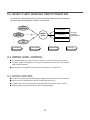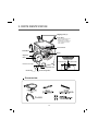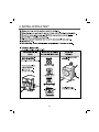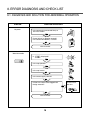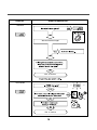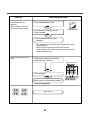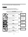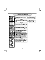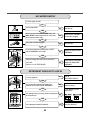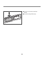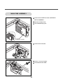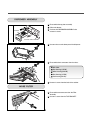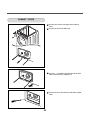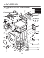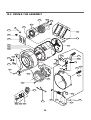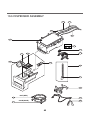
1
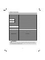
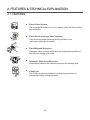
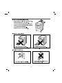
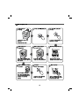
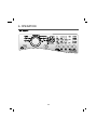
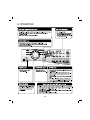
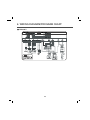
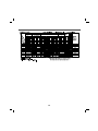
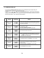
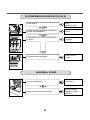
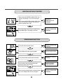
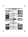
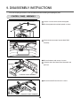
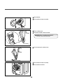
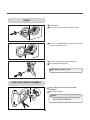
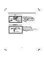
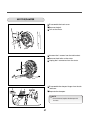
WASHING MACHINE SERVICE MANUAL CAUTION READ THIS MANUAL CAREFULLY TO DIAGNOSE PROBLEMS CORRECTLY BEFORE SERVICING THE UNIT. MODEL : WM2240C* Jul. 2010 PRINTED IN KOREA P/No. : MFL30599179 CONTENTS 1. SPECIFICATIONS ................................................................................................................ 3 2. FEATURES AND TECHNICAL EXPLANATION ............................................................... 4~6 3. PARTS IDENTIFICATION...................................................................................................... 7 4. INSTALLATION AND TEST ............................................................................................ 8~10 5. OPERATION ................................................................................................................. 11~12 6. WIRING DIAGRAM/PROGRAM CHART ...................................................................... 13~14 7. TROUBLESHOOTING .................................................................................................. 15~17 7-1. BEFORE PERFORMING SERVICE .......................................................................... 15 7-2. QC TEST MODE ....................................................................................................... 15 7-3. HOW TO CHECK THE WATER LEVEL FREQUENCY ............................................. 15 7-4. ERROR DISPLAY ................................................................................................ 16~17 8. DIAGNOSIS AND TROUBLESHOOTING .................................................................. 18~28 8-1. DIAGNOSIS AND SOLUTION FOR ABNORMAL OPERATION ......................... 18~20 8-2. FAULT DIAGNOSIS AND TROUBLESHOOTING ............................................... 21~28 9. DISASSEMBLY INSTRUCTIONS.................................................................................. 29~37 10. EXPLODED VIEW ...................................................................................................... 38~40 10-1. CABINET & CONTROL PANEL ASSEMBLY........................................................... 38 10-2. DRUM & TUB ASSEMBLY ...................................................................................... 39 10-3. DISPENSER ASSEMBLY ........................................................................................ 40 2 1. SPECIFICATIONS ITEM WM2240C* COLOR W:BLUE WHITE POWER SUPPLY AC 120 V, 60 Hz PRODUCT WEIGHT 190 lbs. (86kg) ELECTRIC POWER CONSUMTION WASHING 280 W DRAIN MOTOR 80 W WASH 42 rpm SPIN 0 - 1200 rpm REVOLUTION SPEED CYCLES 7 WASH/RINSE TEMPERATURES 5 SPIN SPEEDS 5 OPTIONS Prewash, Rinse+Spin, Quick Cycle, Stain Cycle, Tub Clean, Delay Wash, Water Plus, Extra Rinse CUSTOM PROGRAM - WATER CIRCULATION - OPERATIONAL WATER PRESSURE 14.5 - 116 psi (800 kPa) CONTROL TYPE Electronic DIMENSIONS 27” (W) X 301/32” (D) X 3811/16” (H), X 5013/16” (D door open) DELAY WASH up to 19 hours DOOR SWITCH TYPE PTC + Solenoid WATER LEVEL 12 Step (by sensor) LAUNDRY LOAD SENSING Incorporated ERROR DIAGNOSIS Incorporated AUTO POWER OFF Incorporated CHILD LOCK Incorporated WARNING • TO reduce the risk of personal injury, adhere to all industry recommended safety procedures including the use of long sleeved gloves and safety glasses. Failure to follow all of the asfty warnings in this manual could result in property damage, personal injury or death. 3 2. FEATURES & TECHNICAL EXPLANATION 2-1. FEATURES Direct Drive System The advanced Brushless DC motor directly drives the drum without belt and pulley. 5 Tilted Drum and Large Door Opening Tilted drum and large opening make it possible to load and unload clothing more easily. Time-Released Dispenser Detergent, fabric softener and bleach are dispensed separately at the right time during wash cycle. Automatic Wash Load Detection Automatically detects the load and optimizes the washing time. Child Lock The Child lock prevents children from pressing any button to change the settings during operation. 4 2-2. NEURO FUZZY WASHING TIME OPTIMIZATION To get the best washing performance, optimal time is determined by the water temperature, the selected washing temperature, and the size of the load. water temperature washing time selected washing temperature NEUROFUZZY the best washing performance rinsing time spin rhythm, time load size SENSING PROCESSING DETERMINATION EFFECT 2-3. WATER LEVEL CONTROL This model incorporates a pressure sensor which can sense the water level in the tub. The water supply is stopped when the water level reaches the preset level, the washing program then proceeds. Spinning does not proceed until the water in the tub drains to a certain level. 2-4. DOOR CONTROL The door can be opened by pulling the door handle whenever washer is not in operation. When the cycle is completed, the DOOR LOCKED light will turn off. If a power failure has occurred while in operation, the door will unlock after 5 minutes. Clicking sounds can be heard when the door is locked/unlocked. 5 2-5. THE DOOR CAN NOT BE OPENED ● While program is operating ● When a power failed and power plug is taken out in operation ● While Door Lock lights turn on. ● White the motor is in the process of intertial rotating, through the operation is paused. 2-6. DOOR LOCKED LAMP LIGHTS ● When the frequency of water level is lower than 22.9 kHz (It can be canceled when the frequency is more than 23.8 kHz) ● When the temperature inside the tub is higher than 45 °C and water level is not 25.5 kHz (It can be canceled when the water level is 25.5 kHz or the temperature inside the tub is lower than 40 °C) 2-7. CHILD LOCK ● Use this option to prevent unwanted use of the washer. Press and hold OPTION button for 3 seconds to lock/unlock control. ● When Child lock is set, blinks and all buttons are disabled except the Power button. You can lock the washer while it is operating. ● CHILD LOCK lasts after the end of cycle. If you want to deactivate this function,Press and hold the OPTION button for 3 seconds. 6 3. PARTS IDENTIFICATION Shipping Bolts (4) Power Plug If the supply cord is damaged, it must be replaced by the manufacturer or an authorized service technician in order to avoid a hazard. EST. EST. ASH WWASH TIMEE TIM SPIN Control Panel Drain Hose Drum Dispenser Back of Washer Door Cold Water Inlet Air Vent for Safety Lower Cover Cap Adjustable Feet Drain Plug Drain Pump Filter Accessories 7 Hot Water Inlet 4. INSTALLATION & TEST 8 9 TEST OPERATION Preparation for washing. Press the POWER button. Connect the power plug to the outlet. Connect the inlet hoses. Check the water temperature. Press the Start/Pause button. Listen for a click to determine if the door has locked. Check the automatic reverse rotation. Check the water supply. MAX SOFTENER Press the WASH/RINSE button and the present temperature will be displayed. Check the drain and spin functions. Power off and the power on. Press the SPIN SPEED button. Press the START/PAUSE button. Check the spin and drain functions. Check if the drum rotates clockwise and counterclockwise. Press the START/PAUSE button. Listen for a click to determine if the door is unlocking. 10 Check if water is supplied through the detergent dispenser. Water removal If SVC is needed during check, remove the remaining water by pulling out the hose cap. 5. OPERATION ■ WM2240C* 11 5. OPERATION 12 6. WIRING DIAGRAM/PROGRAM CHART ■ WM2240C* 13 Normal Extra Rinse BULKY/ LARGE PERM. PRESS DELICATES COTTON/ NORMAL HAND WASH/ WOOL SPEED WASH DRAIN+ SPIN !" # # $" ! %& # '!( " " ! )* ! #! ! !#+ #! 14 7. TROUBLESHOOTING 7-1. BEFORE PERFORMING SERVICE ■ Be careful of electric shock when disconnecting parts while troubleshooting. ■ The voltage of each terminal is 120 V AC and DC when the unit is plugged in. 7-2. QC TEST MODE. The washer must be empty and the controls must be in the off state. 1. Press the SPIN SPEED and SOIL LEVEL buttons simultaneously. 2. Press the Power button, while the above condition. Then buzzer will sound twice. 3. Press the Start/Pause button repeatedly to cycle through the test modes. 4. Alternate blinking of , and Number of times the Start/Pause button is pressed Check Point Display Status None Turns on all lamps and locks the door. 1 time Tumble clockwise. rpm (40~50) 2 times Low speed Spin. rpm 3 times High speed Spin. rpm 4 times Inlet valve for prewash turns on. Water level frequency (25~65) 5 times Inlet valve for main wash turns on. Water level frequency (25~65) 6 times Inlet valve for hot water turns on. Water level frequency (25~65) 7 times Inlet valve for bleach turns on. Water level frequency (25~65) 8 times Tumble counterclockwise. rpm (40~50) 9 times Water temperature (Thermistor) Water temperature [°C] 10 times Drain pump turns on. Water level frequency (25~65) 11 times Power off and unlock the door. Turn off all lamps. 7-3. HOW TO CHECK THE WATER LEVEL FREQUENCY Press the Delay and Signal button simultaneously. The digits indicate the water level frequency ( x.1 kHz ). So, for example a display indicating 241: a Water level frequency of 241 x.1 kHz = 24.1 kHz 15 7-4. ERROR DISPLAY If you press the START/PAUSE button when an error is displayed, any error except will disappear and the machine will go into the pause status. In case of if the error is not resolved within 20 sec., or the in case of other errors, if the error is not resolved within 4 min., power will be turned off automatically and the error code will blink. But in the case of , power will not be turned off. ERROR SYMPTOM CAUSE • Correct water level (246) is not reached within 8 minutes after water is supplied or it does not reach the preset water level within 25 minutes. 1 WATER INLET ERROR 2 IMBALANCE ERROR 3 DRAIN ERROR 4 OVER FLOW ERROR • Water is overflowing (water level frequency is over 213). If is displayed, the drain pump will operate to drain the water automatically. 5 PRESSURE SENSOR ERROR • The SENSOR SWITCH ASSEMBLY is out of order. 6 DOOR OPEN ERROR • Door not all the way closed. • Loose electrical connections at Door switch and PWB Assembly. • The DOOR SWITCH ASSEMBLY is out of order. 7 THERMISTOR ERROR • The THERMISTOR is out order. • The load is too small. • The appliance is tilted. • Laundry is gathered to one side. • Non distributable things are put into the drum. • Not fully drained within 10 minutes. 16 17 8. ERROR DIAGNOSIS AND CHECK LIST 8-1. DIAGNOSIS AND SOLUTION FOR ABNORMAL OPERATION SYMPTOM No power GUIDE FOR SERVICE CALL Is the power plug connected firmly to 120 V AC outlet? YES Power failure? or Breaker opened? Is the outlet controlled by a switch? NO Visit to service. Water inlet trouble Is displayed? YES Is the tap opened? YES Is the tap frozen? NO Is the water supply shut-off? NO Is filter in the inlet valve clogged with foreign material? NO Visit to service. 18 YES Clean the filter of inlet valve SYMPTOM GUIDE FOR SERVICE CALL Door error Was the load too large? Visit to service. Drain trouble Visit to service. 19 SYMPTOM Suds overflow from the appliance. (In this condition, wash and spin do not operate normally) GUIDE FOR SERVICE CALL Is a low-sudsing detergent used? YES Is the proper amount of detergent used as recommended? LOW-SUDSING YES Recommend to reduce the amount of detergent. This appliance has an automatic suds sensing function which prevents overflow. When excessive suds are sensed, the suds removing implementations such as drain, water input, pause will operate, without rotating the drum. Liquid laundry products do not flow in. Is liquid laundry product put in the correct compartment of the dispenser? YES Is the cap clogged? YES Explain proper use of liquid laundry products. Clean the compartment. Visit to service. 20 4 (4) Main Wash Compartment 8-2. FAULT DIAGNOSIS AND TROUBLESHOOTING CAUTION 1. Be careful of electric shock if disconnecting parts while troubleshooting. 2. First of all, check the connection of each electrical terminal with the wiring diagram. 3. If you replace the MAIN PWB ASSEMBLY, reinsert the connectors correctly. NO POWER Is the supplied voltage 120 V AC? NO Check the fuse or reset the circuit breaker. NO Replace the FILTER ASSEMBLY (CIRC). NO Replace MAIN PWB ASSEMBLY. YES Reconnect. NO Replace the MAIN PWB ASSEMBLY. YES Is the voltage between the pins of 2 FILTER ASSEMBLY connector 120 V AC? YES BL OR RD BL WH BL RD Is the LED (1) on? BL WH WH BL WH YES (1) BL OR RD BL WH Are the connectors (2) on the PWB loose? BL RD BL WH WH WH (2) BL NO Is wire of the DISPLAY PWB ASSEMBLY broken? YES Replace DISPLAY PWB ASSEMBLY or repair wire. 21 22 If it still has severe vibration and noise, regulate a specific spin speed that generates excessive vibration and noise as follows: 1) Put an unbalance part (rubber) inside of the drum. 2) Start the QC test mode (Refer to section 7-2). 3) Press Delay Wash button, then ' ' is displayed. 4) Press the Spin Speed button repeatedly to select EXTRA HIGH. 5) Press the Start/Pause button. 6) Press the Signal button repeatedly to set spin speed (600, 700, 800, 900, 1000, 1100 rpm) and check if there is vibration and noise. 7) If there is no vibration and noise, increase the spin speed by pressing Signal button. 8) If there is vibration and noise, press the Cycle selector button to reduce the Spin Speed (reduce by 50 and 100 rpm). In case of 600 rpm, it can not reduce the spin speed. 9) If vibration and noise are reduced, press the WASH/RINSE button to store (2 beep sounds). * If you want to return to factory default spin speed setting, repeat above steps except step 8). 23 NO WATER SUPPLY Is water supply shut-off? NO Is the tap opened? NO Open the tap. YES Check the AIR CHAMBER and the tube (clogged). YES Clean the filter. NO Replace the INLET VALVE ASSEMBLY. NO Check electrical connection. Replace the MAIN PWB ASSEMBLY. YES When you press both SPIN SPEED button and SOIL LEVEL button simultaneously, is the water level frequency below 246? NO Is the inlet valve filter clogged? NO Is resistance between each terminal of INLET VALVE ASSEMBLY 0.8-1.2 kΩ? YES Verify the voltage of the inlet valve connector is 120 V AC. (Refer to 7-2 QC TEST MODE) DETERGENT DOES NOT FLOW IN Is water supplied? NO Refer to NO WATER SUPPLY NO Check the wiring. YES Are receptacles correctly connected to the terminals of the INLET VALVE ASSEMBLY? YES Put the detergent in the correct place. Has detergent been put in the correct compartment NO of the dispenser? YES 4 Is the detergent caked or hardened? (4) Main Wash Compartment 24 YES Clean the dispenser. SOFTENER/BLEACH DOES NOT FLOW IN Hot water Prewash Bleach Main wash Is water supplied? Refer to NO WATER SUPPLY Are the plugs correctly connected to the terminals of the INLET VALVE ASSEMBLY? Check the wiring on the dispenser. Is softener/bleach put in the correct compartment of the drawer? Put it in the correct compartment. Is the softener/bleach cap clogged? Clean the Cap and Container. 4 (4) Main Wash Compartment Bleach cap SOFTENER Softener cap ABNORMAL SOUND Is the motor bolt loosened? Secure the bolt. Is there friction noise coming from the motor? Replace the STATOR ASSEMBLY or ROTOR ASSEMBLY. 25 HEATING WITHOUT WATER When pressing SPIN SPEED and SOIL LEVEL at the same time after draining, is the water level frequency 255? When pressing SPIN SPEED and SOIL LEVEL buttons at the same time while washing, is the water level frequency between 230 - 243 ? BL OR 2 1 NO Replace the SENSOR SWITCH ASSEMBLY. YES Replace the MAIN PWB ASSEMBLY. YES Repair the DRAIN HOSE ASSEMBLY. YES Remove foreign material. YES Reconnect or repair the connector YES Replace the DRAIN PUMP ASSEMBLY. NO Replace the MAIN PWB ASSEMBLY. YES 2 1 RD BL WH BL RD BL WH WH BL WH Check the voltage between two pins while pressing the POWER button. Is the voltage 120 V AC? DRAIN MALFUNCTION Is the drain hose twisted or frozen? NO Is the impeller of the drain pump clogged? NO Is the connector disconnected, disassembled? NO Is the coil of the drain pump too high or low? (resistance of the coil is 10-20 Ω) BL OR 2 1 NO 2 1 RD BL WH BL RD BL WH WH WH When checking voltage between connectors during BL spin, is the voltage 120 V AC as in the figure? 26 28 9. DISASSEMBLY INSTRUCTIONS Be sure to unplug the machine out of the outlet before disassembling and repairing the parts. Unscrew 2 screws on the back of the top plate. Pull the top plate backward and upward as shown. Disconnect the connectors from the Main PWB Assembly Pull out the drawer and unscrew 2 screws. Lift the left side of the Control Panel Assembly and DRAWER pull it out. CONTROL PANEL ASSEMBLY Pull out the control Panel unscrew 1 screws. CONTROL PANEL ASSEMBLY 29 Unscrew the 9 screws from the Control Panel Assembly. Disassemble the Display PWB Assembly. 30 Disconnect the POWER connector and SENSOR SWITCH ASSEMBLY. Remove the Protect Cover. Disassembled keeping wire. PROTECT COVER Disconnect the connectors. Unscrew 1 screw on the back. Disassemble the Main PWB. 31 Disassemble the top plate assembly. Pull out the drawer. Push out the DISPENSER ASSEMBLY after unscrew 2 screws. DRAWER CONTROL PANEL ASSEMBLY Unscrew the nut at the lower part of the dispenser. Disassemble the 4 connectors from the valves. Wire Color Blue Housing (OR-BK) White Housing (WH-BK) Blue Housing (GY-BK) Red Housing (BL-BK) Unscrew 2 screws from the back of the cabinet. Disassemble two connectors from the Filter Assembly. Unscrew a screw from the TOP BRACKET. 32 Unscrew the 3 screws from upper of the canbinet cover. Unscrew the screw from filter cover. Put a flat ( - ) screwdriver or putty knife into the both sides of the filter cover, and pull it out. Unscrew the screw from the lower side of the cabinet cover. 33 Open the door. Disassemble the clamp assembly. Tilt the cabinet cover. Disconnect the door switch connector. NOTE: When assembling the CABINET COVER, connect the connector. Lift and separate the cabinet cover. Disassemble the clamp assembly. Disassemble the Gasket. 34 Open the door. Unscrew the 7 screws from the HINGE COVER. Put a flat ( - ) screwdriver into the openng of the hinge, and pull out the hinge cover. Unscrew a screw from the lower side of door. Disassemble the door upward. Be careful! The door is heavy. Open the door and disassemble the CLAMP ASSEMBLY. Unscrew the 2 screws. NOTE • Reconnect the connector after replacing the DOOR SWITCH ASSEMBLY. 35 36 Disassemble the back cover. Remove the bolt. Pull out the Rotor. Unscrew the 2 screws from the tub bracket. Remove the 6 bolts on the stator. Unplug the 2 connectors from the stator. Disassemble the damper hinges from the tub and base. Separate the dampers. NOTE • Once removed, replace the damper with new one. 37 10. EXPLODED VIEW 10-1. CABINET & CONTROL PANEL ASSEMBLY “The following parts are not illustrated" Description F215 Loc No. *Owner’s Manual G001 *Energy Label G002 *Service Manual G004 Printed materials *Wiring Diagram A485 F210 G005 *Quick Start Guides G006 *Installation Sheet G007 *Non-Skid Pads G010 A410 F110 A455 A450 A110 A102 A111 A105 A106 A103 A150 A175 A104 A154 A152 A153 A101 A141 A156 A157 A390 A151 A100 A131 A130 A430 A140 A133 A440 A155 A300 A310 A201 A220 A303 A200 38 10-2. DRUM & TUB ASSEMBLY K143 K360 K123 K350 K351 F140 K610 K411 K611 K410 K115 K110 K141 K111 K140 K117 K142 K571 F310 K572 F315 F465 K190 K570 K530 F463 K130 F464 K122 K125 K516 K310 K510 K311 K121 K135 K131 K340 F467 F145 F468 K520 K550 F461 K540 K346 K344 K342 39 K105 10-3. DISPENSER ASSEMBLY F323 F322 F462 F321 F300 Inlet Valve Filter SVC F180 COLD (BLUE) HOT (ORANGE) F170 F227 F160 F226 F220 F225 F430 F441 F120 A275 A276 HOT (RED) F130 F432 COLD (BLUE) 40