1
Commercial Air Conditioning
SERVICE MANUAL
Inverter R410a 50/60HZ
Models
Indoor:
Outdoor:
1
YHKJXH012BAM--FX
YHKJXH024BAR--FX
YHKJXH036BAR--FX
YHKJXH048BAR--FX
YHFJXH012BAM--FX
YHFJXH024BAR--FX
YHFJXH036BAR--FX
YHFJXH048BAR--FX
YHDJXH012BAM--GX
YHDJXH024BAR--GX
YHEJXH028BAR--GX
YHEJXH048BAR--GX
YHGJXH048BAR--GX
YHGJXH060BAR--GX
YHUJYH024BAR-A-X
YHUJYH028BAR-A-X
YHUJYH036BAR-A-X
YHUJYH048BAR-A-X
YHUJYH048BAS-A-X
YHUJYH060BAS-A-X
YHKJXH018BAM--FX
YHKJXH028BAR--FX
YHKJXH048BAR--FX
YHKJXH060BAR--FX
YHFJXH018BAM--FX
YHFJXH028BAR--FX
YHFJXH048BAR--FX
YHFJXH060BAR--FX
YHDJXH018BAM--GX
YHEJXH024BAR--GX
YHEJXH036BAR--GX
YHEJXH048BAR--GX
YHGJXH048BAR--GX
CONTENTS
Contents………………………………………………………......2
1. Description of products & features…………………………..3
2. Specification…………………………………………………...5
3. Dimensions…………………………………………………....33
4. Pipe and wiring installation…..……………………………...40
5. PCB photo, wiring diagram and function description……..92
6. Diagnostic code and troubleshooting.…………………….122
7. Outdoor performance curves………..……………………..128
8. Indoor air velocity and temperature distribution curves....133
9. Air flow and static pressure chart…………………………..135
10. Noise level…………………………………………………..137
11. Sensor characteristic….…………………………………...150
12. Controller functions…...…………………………………....152
2
1.Description of products & features
1.1 Brief Introduction for T1 working condition
Climate type
Type of Conditioner
T1˄ć˅
Cooling Only
18ć~46ć
Heat Pump
-15ć ~ 46ć
~46 ć
Electricity Heating
1.2 Operating Range of Air Conditioners
Working temperature range
Cooling
Heating
rated
maximum
minimum
DBć
27
32
18
WBć
19
23
14
DBć
35
46
10
WBć
24
24
—
DBć
20
27
15
WBć
14.5
—
—
DBć
7
24
―15
WBć
6
18
—
3
1.3 Product features
Super match
By integrating intelligential technology of Haier A/C group, super match air conditioner,
with universal indoor and outdoor units, make more intelligent and flexible choices on
purchasing, easier inventory management to every customer.
Good for choice
Multi-choice of capacity and appearance of indoor unit according to various rooms.
DC scroll compressor
The highly efficient scroll compressor is equipped with a “flexible Mechanism” that
allows movement in the axial direction of the frame supporting the cradle scroll. This
greatly reduces both leakage and friction loss, ensuring very high efficiency
throughout the speed range.
DC inverter technology
Powerful startup: Haier DC inverter system can startup and running at maximum
frequency very quickly in order to reach the set temperature in the shorter time, which
brings you great comfort experience.
Minimum running: Haier DC inverter system will reduce the frequency and running
smoothly according to the real load after reach the set temperature. The system
funning cost reduced drastically which brings you real benefit of money saving.
Automatic control
Precise control: The temperature sensor can measure the temperature precisely with
only 0.5℃ tolerance, which transfers the exact requirement to the system to adjust the
compressor frequency accordingly.
Once reach the set temperature, the system adjust the frequency smoothly according
to the real time request and always maintain the temperature without fluctuation.
Wider operation range
Haier DC inverter system provide much wider working range that is suitable for
special cooling, heating requirement.
The Unitary Smart DC inv. outdoor unit default production with AC fan motor, DC fan
motor is for optional choice with additional cost.
4
2.Specification
Model name
Unit
YHKJZH012BAM-AFX
YHKJZH018BAM-AFX
Outdoor
YHUJYH012BAM-A-X
YHUJYH018BAM-A-X
Indoor
YHKJXH012BAM--FX
YHKJXH018BAM--FX
V/Ph/Hz
230/1/50
230/1/50
Capacity
kW(min~max)
3.5(0.9~4.5)
4.8(1.8~5.8)
Input
W(min~max)
1080(280~1650)
1490(550~2000)
Rated current
EER
SEER
Capacity
A
W/W
W/W
Btu/h
5
3.24
5.1
12371.4
6.8
3.22
5.1
17375
Input
W(min~max)
995(280~1650)
1580(600~2000)
Rated current
COP
SCOP
A
W/W
W/W
4.7
3.62
3.64
6.7
3.22
3.4
Heating P design(-10℃ )
kW
3.4
4.8
l/h
W
A
A
1.6
1800
8
3
1.8
2000
9.5
3
Wired&Wireless
Wired&Wireless
2
2
1.25
1.25
Hydrophilic Aluminium
Hydrophilic Aluminium
7
7
Tube material
Inner Grooved copper tube
Inner Grooved copper tube
Number of circuit
4
4
YORK
Power supply
Rated Cooling
Rated
Heating
Moisture Removal
Max. input consumption
Max. current
Starting current
Operation Control
Number of row
Fin spacing
mm
Fin material
Indoor coil
Indoor fan
motor
Tube outside diameter
Input
Output
W
W
30
11
62
18
Running current
A
0.18
0.24
Capacitor
uF
2
2
Speed (Hi/Me/Lo)
rpm
690/520/560
795/690/550
m3/h
620/520/450
700/620/500
dB(A)
53/49/45
55/50/47
dB(A)
40/36/32
42/37/35
mm
570×570×260
570×570×260
mm
718×680×380
718×680×380
Net
Gross
Unit (WxDxH)
kg
kg
mm
18.5
23
700×700×60
18.5
23
700×700×60
Packing (WxDxH)
mm
740×750×115
740×750×115
Net
Gross
kg
kg
2.8
4.8
2.8
4.8
Indoor air flow at 0/50/100 Pa(Hi/Me/Lo)
Indoor noise level(Sound power level) (Hi/
Me/Lo)
Indoor noise level (Sound pressure level)
(Hi/Me/Lo)
Unit (WxDxH)
Indoor
dimension
Packing (WxDxH)
Indoor weight
Panel
dimension
Panel weight
mm
5
Model name
Unit
YHKJZH012BAM-AFX
YHKJZH018BAM-AFX
Outdoor
YHUJYH012BAM-A-X
YHUJYH018BAM-A-X
Indoor
YHKJXH012BAM--FX
YHKJXH018BAM--FX
2
2
1.75
1.41
Hydrophilic Aluminium
Hydrophilic Aluminium
9.52
7
Inner Grooved copper tube
Inner Grooved copper tube
793 x43.3x550
793 x26.6x462
Number of circuit
4
3
Type
Capacity
Input
W/h
W
Rotary
9043.92
690
Rotary
13992.48
1245
Rated current(RLA)
A
2650
8.4
115
120
YORK
Number of row
Fin spacing
mm
Fin material
Outdoor coil
Tube outside diameter
mm
Tube material
Coil length x height x width
Compressor
mm
Thermal protector
Refrigerant oil
Input
Output
ml
W
W
370
62
40
500
56
41
Running current
A
0.2
0.25
rpm
m3/h
dB(A)
850
1900
62
860
2200
64
dB(A)
54
54
mm
780×245×540
810×288×688
mm
930×340×614
949×406×745
kg
kg
g
mm
mm
32
35
R410A
1100
6.35
9.52
43
45.5
R410A
1300
6.35
12.7
m
15
25
Max. difference in level
m
10
15
Operation temperature range
Ambient temperature range (Cooling)
Ambient temperature range (Heating)
Application area
℃
℃
℃
m2
16~30
18~43
-15~24
25
16~30
18~43
-15~24
35
Outdoor fan
motor
Speed
Outdoor air flow
Outdoor noise level (Sound power level)
Outdoor noise level (Sound pressure
level)
Unit (WxDxH)
Outdoor
dimension
Packing (WxDxH)
Outdoor
weight
Refrigerant
Net
Gross
Type
Charge
Liquid side
Gas side
Refrigerant
Max. refrigerant pipe length
pipe
6
Model name
Unit
YHKJZH024BAR-AFX
YHKJZH028BAR-AFX
Outdoor
YHUJYH024BAR-A-X
YHUJYH028BAR-A-X
Indoor
YHKJXH024BAR--FX
YHKJXH028BAR--FX
V/Ph/Hz
230/1/50(60)
230/1/50(60)
Capacity
kW(min~max)
6.9(1.8~7.5)
7.8(2.0~8.7)
Input
W(min~max)
2225(500~2600)
2590(500~3800)
Rated current
EER
SEER
Capacity
A
W/W
W/W
Btu/h
9.4
3.1
5.217391304
24885
10.8
3.01
5.239130435
29008
Input
W(min~max)
2010(500~2600)
2530(500~3800)
Rated current
COP
SCOP
A
W/W
W/W
9
3.63
3.6
11.6
3.36
3.4
Heating P design(-10℃ )
kW
6.5
7.8
l/h
W
A
A
2.5
2600
12
3
2.8
4200
19
3
Wired&Wireless
Wired&Wireless
2
2
1.3
1.3
Hydrophilic Aluminium
Hydrophilic Aluminium
7
7
Tube material
Inner Grooved copper tube
Inner Grooved copper tube
Number of circuit
8
8
YORK
Power supply
Rated Cooling
Rated
Heating
Moisture Removal
Max. input consumption
Max. current
Starting current
Operation Control
Number of row
Fin spacing
mm
Fin material
Indoor coil
Indoor fan
motor
Tube outside diameter
Input
Output
W
W
140
40
140
40
Running current
A
0.65
0.65
Capacitor
uF
3
3
Speed (Hi/Me/Lo)
rpm
710/620/520
710/620/520
m3/h
1300/1100/870
1300/1100/870
dB(A)
59/57/52
61/59/57
dB(A)
46/44/39
48/46/44
mm
840×840×240
840×840×240
mm
930×930×330
930×930×330
Net
Gross
Unit (WxDxH)
kg
kg
mm
26.8
32.6
950×950×60
26.8
32.6
950×950×60
Packing (WxDxH)
mm
985×985×115
985×985×115
Net
Gross
kg
kg
6
7.5
6
7.5
Indoor air flow at 0/50/100 Pa(Hi/Me/Lo)
Indoor noise level(Sound power level) (Hi/
Me/Lo)
Indoor noise level (Sound pressure level)
(Hi/Me/Lo)
Unit (WxDxH)
Indoor
dimension
Packing (WxDxH)
Indoor weight
Panel
dimension
Panel weight
mm
7
Model name
Unit
YHKJZH024BAR-AFX
YHKJZH028BAR-AFX
Outdoor
YHUJYH024BAR-A-X
YHUJYH028BAR-A-X
Indoor
YHKJXH024BAR--FX
YHKJXH028BAR--FX
2
2
1.65
1.7
Hydrophilic Aluminium
Hydrophilic Aluminium
7.94
7.94
Inner Grooved copper tube
Inner Grooved copper tube
840 x39.9x700
855 x38.1x792
Number of circuit
4
6
Type
Capacity
Input
W/h
W
Rotary
13992.48
1245
Rotary
24333.264
2200(60Hz)
Rated current(RLA)
A
8.4
9.7
120
120
YORK
Number of row
Fin spacing
mm
Fin material
Outdoor coil
Tube outside diameter
mm
Tube material
Coil length x height x width
Compressor
mm
Thermal protector
Refrigerant oil
Input
Output
ml
W
W
500
85
70
870
145
100
Running current
A
0.4
0.4
rpm
m3/h
dB(A)
880
3000
68
900
3500
69
dB(A)
57
58
mm
860×308×730
948×340×840
mm
995×420×815
1040×430×1000
kg
kg
g
mm
mm
49
52
R410A
1600
9.52
15.88
64
73
R410A
2600
9.52
15.88
m
25
30
Max. difference in level
m
15
20
Operation temperature range
Ambient temperature range (Cooling)
Ambient temperature range (Heating)
Application area
℃
℃
℃
m2
16~30
-10~46
-15~24
45
16~30
-10~46
-15~24
55
Outdoor fan
motor
Speed
Outdoor air flow
Outdoor noise level (Sound power level)
Outdoor noise level (Sound pressure
level)
Unit (WxDxH)
Outdoor
dimension
Packing (WxDxH)
Outdoor
weight
Refrigerant
Net
Gross
Type
Charge
Liquid side
Gas side
Refrigerant
Max. refrigerant pipe length
pipe
8
Model name
Unit
YHKJZH036BAR-AFX
YHKJZH048BAR-AFX
Outdoor
YHUJYH036BAR-A-X
YHUJYH048BAR-A-X
Indoor
YHKJXH036BAR--FX
YHKJXH048BAR--FX
V/Ph/Hz
230/1/50(60)
230/1/50(60)
Capacity
kW(min~max)
9.3(2.0~10.3)
12.1(6.0~13.8)
Input
W(min~max)
3000(500~3800)
4115(2000~6000)
Rated current
EER
SEER
Capacity
A
W/W
W/W
Btu/h
12.87
3.097826087
5.347826087
32030.55
18
2.94
/
43121.875
Input
W(min~max)
2780(500~3800)
4070(2000~6000)
Rated current
COP
SCOP
A
W/W
W/W
12.1
3.38
3.6
18
3.10
/
Heating P design(-10℃ )
kW
9.1
/
l/h
W
A
A
3
4500
20
3
3.8
6000
26
3
Wired&Wireless
Wired&Wireless
2
2
1.4
1.4
Hydrophilic Aluminium
Hydrophilic Aluminium
7
7
Tube material
Inner Grooved copper tube
Inner Grooved copper tube
Number of circuit
11
11
YORK
Power supply
Rated Cooling
Rated
Heating
Moisture Removal
Max. input consumption
Max. current
Starting current
Operation Control
Number of row
Fin spacing
mm
Fin material
Indoor coil
Indoor fan
motor
Tube outside diameter
Input
Output
W
W
150
50
150
50
Running current
A
0.68
0.68
Capacitor
uF
8
8
Speed (Hi/Me/Lo)
rpm
680/610/530
680/610/530
m3/h
1600/1450/1300
1600/1450/1300
dB(A)
62/60/57
/
dB(A)
49/47/44
49/47/44
mm
840×840×290
840×840×290
mm
930×930×390
930×930×390
Net
Gross
Unit (WxDxH)
kg
kg
mm
31
37
950×950×60
31
37
950×950×60
Packing (WxDxH)
mm
985×985×115
985×985×115
Net
Gross
kg
kg
6
7.5
6
7.5
Indoor air flow at 0/50/100 Pa(Hi/Me/Lo)
Indoor noise level(Sound power level) (Hi/
Me/Lo)
Indoor noise level (Sound pressure level)
(Hi/Me/Lo)
Unit (WxDxH)
Indoor
dimension
Packing (WxDxH)
Indoor weight
Panel
dimension
Panel weight
mm
9
Model name
Unit
YHKJZH036BAR-AFX
YHKJZH048BAR-AFX
Outdoor
YHUJYH036BAR-A-X
YHUJYH048BAR-A-X
Indoor
YHKJXH036BAR--FX
YHKJXH048BAR--FX
3
2
1.55
1.4
Hydrophilic Aluminium
Hydrophilic Aluminium
7.0
7.94
Inner Grooved copper tube
Inner Grooved copper tube
960 x39.9x792
792x38.1x995
Number of circuit
8 in 4 out
9
Type
Capacity
Input
W/h
W
Rotary
24333.264
2200(60Hz)
Rotary
33718.464
3010
Rated current(RLA)
A
9.7
9.3
120
120
YORK
Number of row
Fin spacing
mm
Fin material
Outdoor coil
Tube outside diameter
mm
Tube material
Coil length x height x width
Compressor
mm
Thermal protector
Refrigerant oil
Input
Output
ml
W
W
870
145
100
870
180
151
Running current
A
0.4
0.8
rpm
m3/h
dB(A)
900
3500
69
850
4200
73
dB(A)
58
59
mm
948×340×840
1008×410×830
mm
1040×430×1000
1130×490×930
kg
kg
g
mm
mm
65
74
R410A
2700
9.52
15.88
82
93
R410A
2850
9.52
19.05
m
30
50
Max. difference in level
m
20
30
Operation temperature range
Ambient temperature range (Cooling)
Ambient temperature range (Heating)
Application area
℃
℃
℃
m2
16~30
-10~46
-15~24
65
16~30
-10~46
-15~24
82
Outdoor fan
motor
Speed
Outdoor air flow
Outdoor noise level (Sound power level)
Outdoor noise level (Sound pressure
level)
Unit (WxDxH)
Outdoor
dimension
Packing (WxDxH)
Outdoor
weight
Refrigerant
Net
Gross
Type
Charge
Liquid side
Gas side
Refrigerant
Max. refrigerant pipe length
pipe
10
Model name
Unit
YHKJZH048BAS-AFX
YHKJZH060BAS-AFX
Outdoor
YHUJYH048BAS-A-X
YHUJYH060BAS-A-X
Indoor
YHKJXH048BAR--FX
YHKJXH060BAR--FX
V/Ph/Hz
400/3/50(60)
400/3/50(60)
Capacity
kW(min~max)
12.1(6.0~13.8)
14.4(3.7~15.1)
Input
W(min~max)
4296(2000~6000)
5124(2000~6500)
Rated current
EER
SEER
Capacity
A
W/W
W/W
Btu/h
6.5
2.815217391
/
42304.5
8.5
2.81
/
52507.35
Input
W(min~max)
4102(2000~6000)
5110(2000~6500)
Rated current
COP
SCOP
A
W/W
W/W
6.7
3.02
/
8.5
3.01
/
Heating P design(-10℃ )
kW
/
/
l/h
W
A
A
3.8
6000
10
3
5
6500
10.5
3
Wired&Wireless
Wired&Wireless
2
2
1.4
1.3
Hydrophilic Aluminium
Hydrophilic Aluminium
7
7
Tube material
Inner Grooved copper tube
Inner Grooved copper tube
Number of circuit
11
10
YORK
Power supply
Rated Cooling
Rated
Heating
Moisture Removal
Max. input consumption
Max. current
Starting current
Operation Control
Number of row
Fin spacing
mm
Fin material
Indoor coil
Indoor fan
motor
Tube outside diameter
Input
Output
W
W
150
50
190
60
Running current
A
0.68
1.2
Capacitor
uF
8
4.5
Speed (Hi/Me/Lo)
rpm
680/610/530
670/550/460
m3/h
1600/1450/1300
1980/1750/1500
dB(A)
/
/
dB(A)
49/47/44
49/44/42
mm
840×840×290
1230×840×280
mm
930×930×390
1325×920×370
Net
Gross
Unit (WxDxH)
kg
kg
mm
31
37
950×950×60
38.6
45.7
1340×950×80
Packing (WxDxH)
mm
985×985×115
1400×995×115
Net
Gross
kg
kg
6
7.5
8.4
12.7
Indoor air flow at 0/50/100 Pa(Hi/Me/Lo)
Indoor noise level(Sound power level) (Hi/
Me/Lo)
Indoor noise level (Sound pressure level)
(Hi/Me/Lo)
Unit (WxDxH)
Indoor
dimension
Packing (WxDxH)
Indoor weight
Panel
dimension
Panel weight
mm
11
Model name
Unit
2
2
Outdoor
1.4
1.5
Indoor
Hydrophilic Aluminium
Hydrophilic Aluminium
7.94
7.94
Inner Grooved copper tube
Inner Grooved copper tube
792x38.1x995
970x38.1x1200
9
10
Rotary
Rotary
33718.464
47710.944
Number of circuit
3010
4270
Type
Capacity
Input
W/h
W
9.3
120
870
12
120
1400
Rated current(RLA)
A
257
120
142
100
YORK
Number of row
Fin spacing
mm
Fin material
Outdoor coil
Tube outside diameter
mm
Tube material
Coil length x height x width
Compressor
mm
Thermal protector
Refrigerant oil
Input
Output
ml
W
W
1.1
850
4200
0.4
930
6500
Running current
A
73
75
rpm
m3/h
dB(A)
59
1008×410×830
1130×490×930
60
948×340×1250
1095×410×1400
dB(A)
82
96
mm
93
106
mm
R410A
R410A
kg
kg
g
mm
mm
2850
9.52
19.05
50
30
16~30
3300
9.52
19.05
50
30
16~30
m
-10~46
-10~46
Max. difference in level
m
-15~24
-15~24
Operation temperature range
Ambient temperature range (Cooling)
Ambient temperature range (Heating)
Application area
℃
℃
℃
m2
82
-10~46
-15~24
65
100
-10~46
-15~24
82
Outdoor fan
motor
Speed
Outdoor air flow
Outdoor noise level (Sound power level)
Outdoor noise level (Sound pressure
level)
Unit (WxDxH)
Outdoor
dimension
Packing (WxDxH)
Outdoor
weight
Refrigerant
Net
Gross
Type
Charge
Liquid side
Gas side
Refrigerant
Max. refrigerant pipe length
pipe
12
model
YORK
Power supply
Capacity
Capacity
Input
Rated Cooling
Rated current
EER
SEER
Capacity
Capacity
Input
Rated Heating
Rated current
COP
SCOP
Heating P design(-10℃ )
Moisture Removal
Max. input consumption
Max. current
Starting current
Operation Control
Number of row
Fin spacing
Fin material
Tube outside diameter
Indoor coil
Tube material
Coil length x height x width
Number of circuit
Input
Output
Indoor fan motor
Running current
Capacitor
Speed (Hi/Me/Lo)
Indoor air flow at 0/50/100 Pa(Hi/Me/Lo)
Indoor noise level(Sound power level) (Hi/Me/
Lo)
Indoor noise level (Sound pressure level)(Hi/
Me/Lo)
Unit (WxDxH)
Indoor dimension
Packing (WxDxH)
Net
Indoor weight
Gross
Number of row
Fin spacing
Fin material
Tube outside diameter
Outdoor coil
Tube material
Compressor
Coil length x height x width
Number of circuit
Type
Capacity
Input
Rated current(RLA)
Thermal protector
Refrigerant oil
Unit
Outdoor
Indoor
V/Ph/Hz
Btu/h
kW(min ~ max)
W(min ~ max)
A
W/W
W/W
Btu/h
kW(min ~ max)
W(min ~ max)
A
W/W
W/W
kW
l/h
W
A
A
mm
mm
mm
YHFJZH012BAM-AFX
YHUJYH012BAM-A-X
YHFJXH012BAM--FX
230/1/50
12286
3.6(0.9 ~ 4.5)
1118(280 ~ 1650)
5
3.22
5.3
13992
4.1(1 ~ 4.8)
1100(280 ~ 1650)
4.9
3.73
3.8
3.4
1.6
1800
8.0
3
Wired&Wireless
3
1.5
Hydrophilic Aluminium
7
Inner Grooved copper
tube
797x39.9x252
4
YHFJZH018BAM-AFX
YHUJYH018BAM-A-X
YHFJXH018BAM--FX
230/1/50
17064
5.0(1.7 ~ 5.3)
1500(550 ~ 2000)
6.8
3.33
5.6
19111
5.6(1.8 ~ 6.0)
1509(600 ~ 2000)
6.5
3.71
3.6
5
1.8
2000
9.5
3
Wired&Wireless
3
1.5
Hydrophilic Aluminium
7
Inner Grooved copper tube
797x39.9x252
4
W
79
W
A
uF
rpm
m3/h
28
0.32
2
1100/1025/825
650/550/450
96
55
0.55
3
1220/1190/1050
800/720/650
dB(A)
54/50/46
57/54/49
dB(A)
41/37/33
44/41/36
mm
mm
kg
kg
990×199×655
1150×300×750
26.3
32.3
2
1.75
Hydrophilic Aluminium
9.52
Inner Grooved copper
tube
793 x43.3x550
4
Rotary
9043.92
690
2650
115
370
990×199×655
1150×300×750
28.3
34.3
2
1.41
Hydrophilic Aluminium
7
mm
mm
mm
W/h
W
A
ml
13
Inner Grooved copper tube
793 x26.6x462
3
Rotary
13992.48
1245
8.4
120
500
model
YORK
Input
O u t d o o r f a n Output
motor
Running current
Speed
Outdoor air flow
Outdoor noise level (Sound power level)
Outdoor noise level (Sound pressure level)
O u t d o o r Unit (WxDxH)
dimension
Packing (WxDxH)
Net
Outdoor weight
Gross
Type
Refrigerant
Charge
Liquid side
Gas side
Refrigerant pipe
Max. refrigerant pipe length
Max. difference in level
Operation temperature range
Ambient temperature range (Cooling)
Ambient temperature range (Heating)
Application area
Unit
Outdoor
Indoor
W
W
A
rpm
m3/h
dB(A)
dB(A)
mm
mm
kg
kg
YHFJZH012BAM-AFX
YHUJYH012BAM-A-X
YHFJXH012BAM--FX
62
40
0.2
850
1900
62
54
780×245×540
930×340×614
32
35
R410A
1100
6.35
9.52
15
10
16 ~ 30
18 ~ 43
-15 ~ 24
24
g
mm
mm
m
m
℃
℃
℃
m2
14
YHFJZH018BAM-AFX
YHUJYH018BAM-A-X
YHFJXH018BAM--FX
56
41
0.25
860
2200
64
54
810×288×688
949×406×745
43
45.5
R410A
1300
6.35
12.7
25
15
16 ~ 30
18 ~ 43
-15 ~ 24
35
model
YORK
Power supply
Capacity
Capacity
Input
Rated Cooling
Rated current
EER
SEER
Capacity
Capacity
Input
Rated Heating
Rated current
COP
SCOP
Heating P design(-10℃ )
Moisture Removal
Max. input consumption
Max. current
Starting current
Operation Control
Number of row
Fin spacing
Fin material
Tube outside diameter
Indoor coil
Tube material
Coil length x height x width
Number of circuit
Input
Output
Indoor fan motor Running current
Capacitor
Speed (Hi/Me/Lo)
Indoor air flow at 0/50/100 Pa(Hi/Me/Lo)
Indoor noise level(Sound power level) (Hi/Me/
Lo)
Indoor noise level (Sound pressure level)(Hi/
Me/Lo)
Unit (WxDxH)
Indoor dimension
Packing (WxDxH)
Net
Indoor weight
Gross
Number of row
Fin spacing
Fin material
Tube outside diameter
Outdoor coil
Tube material
Compressor
Coil length x height x width
Number of circuit
Type
Capacity
Input
Rated current(RLA)
Thermal protector
Refrigerant oil
Unit
Outdoor
Indoor
V/Ph/Hz
Btu/h
kW(min ~ max)
W(min ~ max)
A
W/W
W/W
Btu/h
kW(min ~ max)
W(min ~ max)
A
W/W
W/W
kW
l/h
W
A
A
W
W
A
uF
rpm
m3/h
YHFJZH024BAR-AFX
YHUJYH024BAR-A-X
YHFJXH024BAR--FX
230/1/50(60)
21842
6.4(1.8 ~ 6.7)
2216(500 ~ 2600)
9.5
2.89
5.2
23890
7.0(2.3 ~ 7.3)
2140(500 ~ 2600)
9.5
3.27
3.6
6.5
2.0
2600
12.0
3
Wired&Wireless
3
1.5
Hydrophilic Aluminium
7
Inner Grooved copper
tube
797x39.9x252
4
96
55
0.55
3
1220/1190/1050
850/800/720
dB(A)
57/54/49
62/58/46
dB(A)
44/41/36
49/45/43
mm
mm
kg
kg
990×199×655
1150×300×750
28.3
34.3
2
1.65
Hydrophilic Aluminium
7.94
Inner Grooved copper
tube
840 x39.9x700
4
Rotary
13992.48
1245
8.4
120
500
1298×240×700
1500×315×790
37
47
2
1.7
Hydrophilic Aluminium
7.94
mm
mm
mm
mm
mm
mm
W/h
W
A
ml
15
YHFJZH028BAR-AFX
YHUJYH028BAR-A-X
YHFJXH028BAR--FX
230/1/50(60)
26620
7.8(1.9 ~ 9.2)
2475(500 ~ 2600)
10.2
3.15
5.7
30751
9.0(2.0 ~ 9.6)
2480500 ~ 2600)
10.2
3.63
3.8
8
2.6
4200
19.0
3
Wired&Wireless
3
1.3
Hydrophilic Aluminium
7
Inner Grooved copper tube
1070x39.9x252
6
145
70
0.82
5
1145/1092/956
1630/1537/1375
Inner Grooved copper tube
855 x38.1x792
6
Rotary
24333
2200(60Hz)
9.7
120
870
model
YORK
Input
O u t d o o r f a n Output
motor
Running current
Speed
Outdoor air flow
Outdoor noise level (Sound power level)
Outdoor noise level (Sound pressure level)
O u t d o o r Unit (WxDxH)
dimension
Packing (WxDxH)
Net
Outdoor weight
Gross
Type
Refrigerant
Charge
Liquid side
Gas side
Refrigerant pipe
Max. refrigerant pipe length
Max. difference in level
Operation temperature range
Ambient temperature range (Cooling)
Ambient temperature range (Heating)
Application area
Unit
Outdoor
Indoor
W
W
A
rpm
m3/h
dB(A)
dB(A)
mm
mm
kg
kg
YHFJZH024BAR-AFX
YHUJYH024BAR-A-X
YHFJXH024BAR--FX
85
70
0.4
880
3000
68
57
860×308×730
995×420×815
49
52
R410A
1600
9.52
15.88
25
15
16~30
-10~46
-15~24
45
g
mm
mm
m
m
℃
℃
℃
m2
16
YHFJZH028BAR-AFX
YHUJYH028BAR-A-X
YHFJXH028BAR--FX
145
100
0.4
900
3500
69
58
948×340×840
1040×430×1000
64
73
R410A
2600
9.52
15.88
30
20
16~30
-10~46
-15~24
55
model
YORK
Power supply
Capacity
Capacity
Input
Rated Cooling
Rated current
EER
SEER
Capacity
Capacity
Input
Rated Heating
Rated current
COP
SCOP
Heating P design(-10℃ )
Moisture Removal
Max. input consumption
Max. current
Starting current
Operation Control
Number of row
Fin spacing
Fin material
Tube outside diameter
Indoor coil
Tube material
Coil length x height x width
Number of circuit
Input
Output
Indoor fan motor Running current
Capacitor
Speed (Hi/Me/Lo)
Indoor air flow at 0/50/100 Pa(Hi/Me/Lo)
Indoor noise level(Sound power level) (Hi/Me/
Lo)
Indoor noise level (Sound pressure level)(Hi/
Me/Lo)
Unit (WxDxH)
Indoor dimension
Packing (WxDxH)
Net
Indoor weight
Gross
Number of row
Fin spacing
Fin material
Tube outside diameter
Outdoor coil
Tube material
Compressor
Coil length x height x width
Number of circuit
Type
Capacity
Input
Rated current(RLA)
Thermal protector
Refrigerant oil
Unit
Outdoor
Indoor
V/Ph/Hz
Btu/h
kW(min ~ max)
W(min ~ max)
A
W/W
W/W
Btu/h
kW(min ~ max)
W(min ~ max)
A
W/W
W/W
kW
l/h
W
A
A
W
W
A
uF
rpm
m3/h
YHFJZH036BAR-AFX
YHUJYH036BAR-A-X
YHFJXH036BAR--FX
230/1/50(60)
31739
9.3(2.0 ~ 10.1)
2982(500 ~ 2800)
10.9
3.11
5.6
36176
10.6(2.0 ~ 10.8)
2910(500 ~ 2800)
12.8
3.62
3.8
9.1
3.1
4500
20.0
3
Wired&Wireless
3
1.3
Hydrophilic Aluminium
7
Inner Grooved copper
tube
1070x39.9x252
6
145
70
0.82
5
1145/1092/956
1630/1537/1375
dB(A)
62/58/46
/
dB(A)
49/45/43
53/51/49
mm
mm
kg
kg
1298×240×700
1500×315×790
37
47
3
1.55
Hydrophilic Aluminium
7.0
Inner Grooved copper
tube
960 x39.9x792
8 in 4 out
Rotary
24333
2200(60Hz)
9.7
120
870
1580×240×700
1710×315×790
54
61
2
1.4
Hydrophilic Aluminium
7.94
mm
mm
mm
mm
mm
mm
W/h
W
A
ml
17
YHFJZH048BAR-AFX
YHUJYH048BAR-A-X
YHFJXH048BAR--FX
230/1/50(60)
42000
12.3(5.5 ~ 13.3)
3975(2000 ~ 6000)
17.5
3.09
/
47104
13.8(5.5 ~ 15.1)
4083(2000 ~ 6000)
18.5
3.38
/
/
4.6
6000
26.0
3
Wired&Wireless
3
1.5
Hydrophilic Aluminium
7
Inner Grooved copper tube
1350x39.9x252
12
198
105
0.65
5
1250/1150/1100
2000/1800/1400
Inner Grooved copper tube
792x38.1x995
9
Rotary
33718
3010
9.3
120
870
model
YORK
Input
O u t d o o r f a n Output
motor
Running current
Speed
Outdoor air flow
Outdoor noise level (Sound power level)
Outdoor noise level (Sound pressure level)
O u t d o o r Unit (WxDxH)
dimension
Packing (WxDxH)
Net
Outdoor weight
Gross
Type
Refrigerant
Charge
Liquid side
Gas side
Refrigerant pipe
Max. refrigerant pipe length
Max. difference in level
Operation temperature range
Ambient temperature range (Cooling)
Ambient temperature range (Heating)
Application area
Unit
Outdoor
Indoor
W
W
A
rpm
m3/h
dB(A)
dB(A)
mm
mm
kg
kg
YHFJZH036BAR-AFX
YHUJYH036BAR-A-X
YHFJXH036BAR--FX
145
100
0.4
900
3500
69
58
948×340×840
1040×430×1000
65
74
R410A
2700
9.52
15.88
30
20
16~30
-10~46
-15~24
65
g
mm
mm
m
m
℃
℃
℃
m2
18
YHFJZH048BAR-AFX
YHUJYH048BAR-A-X
YHFJXH048BAR--FX
180
151
0.8
850
4200
73
59
1008×410×830
1130×490×930
82
93
R410A
2850
9.52
19.05
50
30
16~30
-10~46
-15~24
85
model
YORK
Power supply
Capacity
Capacity
Input
Rated Cooling
Rated current
EER
SEER
Capacity
Capacity
Input
Rated current
Rated Heating
COP
SCOP
Heating P design(-10℃ )
Moisture Removal
Max. input consumption
Max. current
Starting current
Operation Control
Number of row
Fin spacing
Fin material
Tube outside diameter
Indoor coil
Tube material
Coil length x height x width
Number of circuit
Input
Output
Indoor fan motor Running current
Capacitor
Speed (Hi/Me/Lo)
Indoor air flow at 0/50/100 Pa(Hi/Me/Lo)
Indoor noise level(Sound power level) (Hi/Me/
Lo)
Indoor noise level (Sound pressure level)(Hi/
Me/Lo)
Unit (WxDxH)
Indoor dimension
Packing (WxDxH)
Net
Indoor weight
Gross
Number of row
Fin spacing
Fin material
Tube outside diameter
Outdoor coil
Tube material
Compressor
Coil length x height x width
Number of circuit
Type
Capacity
Input
Rated current(RLA)
Thermal protector
Refrigerant oil
Unit
Outdoor
Indoor
V/Ph/Hz
Btu/h
kW(min ~ max)
W(min ~ max)
A
W/W
W/W
Btu/h
kW(min ~ max)
W(min ~ max)
A
W/W
W/W
kW
l/h
W
A
A
W
W
A
uF
rpm
m3/h
YHFJZH048BAS-AFX
YHUJYH048BAS-A-X
YHFJXH048BAR--FX
400/3/50(60)
42000
12.3(5.5 ~ 13.3)
4040(2000 ~ 6000)
6.6
3.04
/
46464
13.6(5.5 ~ 15.1)
4120(2000 ~ 6000)
6.8
3.30
/
/
4.6
6000
10.0
3
Wired&Wireless
3
1.5
Hydrophilic Aluminium
7
Inner Grooved copper
tube
1350x39.9x252
12
198
105
0.65
5
1250/1150/1100
2000/1800/1400
dB(A)
/
/
dB(A)
53/51/49
53/51/49
mm
mm
kg
kg
1580×240×700
1710×315×790
54
61
2
1.4
Hydrophilic Aluminium
7.94
Inner Grooved copper
tube
792x38.1x995
9
Rotary
33718
3010
9.3
120
870
1580×240×700
1710×315×790
54
61
2
1.5
Hydrophilic Aluminium
7.94
mm
mm
mm
mm
mm
mm
W/h
W
A
ml
19
YHFJZH060BAS-AFX
YHUJYH060BAS-A-X
YHFJXH060BAR--FX
400/3/50(60)
50552
14.8(3.7 ~ 15.1)
5028(2000 ~ 6500)
8.5
2.95
/
51761
15.2(3.7 ~ 16.5)
4620(2000 ~ 6500)
8.1
3.28
/
/
5.1
6500
10.5
3
Wired&Wireless
3
1.5
Hydrophilic Aluminium
7
Inner Grooved copper tube
1350x39.9x252
12
198
105
0.65
5
1250/1150/1100
2000/1800/1400
Inner Grooved copper tube
970x43.5x1200
10
Rotary
47711
4270
12
120
1400
model
YORK
Input
O u t d o o r f a n Output
motor
Running current
Speed
Outdoor air flow
Outdoor noise level (Sound power level)
Outdoor noise level (Sound pressure level)
O u t d o o r Unit (WxDxH)
dimension
Packing (WxDxH)
Net
Outdoor weight
Gross
Type
Refrigerant
Charge
Liquid side
Gas side
Refrigerant pipe
Max. refrigerant pipe length
Max. difference in level
Operation temperature range
Ambient temperature range (Cooling)
Ambient temperature range (Heating)
Application area
Unit
Outdoor
Indoor
W
W
A
rpm
m3/h
dB(A)
dB(A)
mm
mm
kg
kg
YHFJZH048BAS-AFX
YHUJYH048BAS-A-X
YHFJXH048BAR--FX
257
142
1.1
850
4200
73
59
1008×410×830
1130×490×930
82
93
R410A
2850
9.52
19.05
50
30
16~30
-10~46
-15~24
83
g
mm
mm
m
m
℃
℃
℃
m2
20
YHFJZH060BAS-AFX
YHUJYH060BAS-A-X
YHFJXH060BAR--FX
120
100
0.4
930
6500
75
60
948×340×1250
1095×410×1400
96
106
R410A
3300
9.52
19.05
50
30
16~30
-10~46
-15~24
100
Model name
YORK
Power supply
Capacity
Capacity
Input
Rated Cooling
Rated current
EER
SEER
Capacity
Capacity
Input
Rated current
Rated Heating
COP
SCOP
Heating P design(-10℃)
Moisture Removal
Max. input consumption
Max. current
Starting current
Operation Control
Number of row
Fin spacing
Fin material
Tube outside diameter
Indoor coil
Tube material
Coil length x height x width
Number of circuit
Input
Output
Running current
Indoor fan motor
Speed (Hi/Me/Lo)
Indoor air flow at 0/50/100
Pa(Hi/Me/Lo)
External static pressure
Indoor noise level(Sound power level) (Hi/Me/
Lo)
Indoor noise level (Sound pressure level)(Hi/
Me/Lo)
Unit (WxDxH)
Indoor dimension
Packing (WxDxH)
Net
Indoor weight
Gross
Number of row
Fin spacing
Fin material
Tube outside diameter
Outdoor coil
Tube material
Compressor
Coil length x height x width
Number of circuit
Type
Capacity
Input
Rated current(RLA)
Thermal protector
Refrigerant oil
Unit
Outdoor
Indoor
V/Ph/Hz
Btu/h
kW(min~max)
W(min~max)
A
W/W
W/W
Btu/h
kW(min~max)
W(min~max)
A
W/W
W/W
kW
l/h
W
A
A
mm
mm
mm
W
W
A
rpm
YHDJZH012BAM-AGX
YHUJYH012BAM-A-X
YHDJXH012BAM--GX
230/1/50
11945
3.5(0.8~4.1)
1080(280~1650)
5
3.24
5.3
13793
4.0(0.9~4.4)
1160(280~1650)
5.1
3.45
3.8
3.4
1.5
1200
8.0
3
Wired&Wireless
3
1.4
Hydrophilic Aluminium
7
Inner Grooved copper
tube
434 x 39.9 x 252
3
40
30
0.5
YHDJZH018BAM-AGX
YHUJYH018BAM-A-X
YHDJXH018BAM--GX
230/1/50
17064
5.0(1.7~5.5)
1553(550~2100)
6.8
3.22
5.6
19112
5.4(1.8~6.0)
1496(600~2100)
6.5
3.61
3.8
5
1.9
2100
10.0
3
Wired&Wireless
2
1.4
Hydrophilic Aluminium
7
Inner Grooved copper tube
895x 26.6 x 252
4
90
74
0.5
m3/h
550
Pa
0/30
0/30
dB(A)
46/41/46
49/43/39
dB(A)
33/28/23
36/30/26
mm
mm
kg
kg
850×420×185
1025×525×260
17
18
2
1.75
Hydrophilic Aluminium
9.52
Inner Grooved copper
tube
793 x43.3x550
4
Rotary
9043.92
690
2650
115
370
1170×420×185
1345×525×260
25
26.5
2
1.41
Hydrophilic Aluminium
7
mm
mm
mm
W/h
W
A
ml
21
Inner Grooved copper tube
793 x26.6x462
3
Rotary
13992.48
1245
8.4
120
500
model
YORK
Input
O u t d o o r f a n Output
motor
Running current
Speed
Outdoor air flow
Outdoor noise level (Sound power level)
Outdoor noise level (Sound pressure level)
O u t d o o r Unit (WxDxH)
dimension
Packing (WxDxH)
Net
Outdoor weight
Gross
Type
Refrigerant
Charge
Liquid side
Gas side
Refrigerant pipe
Max. refrigerant pipe length
Max. difference in level
Operation temperature range
Ambient temperature range (Cooling)
Ambient temperature range (Heating)
Application area
Unit
Outdoor
Indoor
W
W
A
rpm
m3/h
dB(A)
dB(A)
mm
mm
kg
kg
YHDJZH012BAM-AGX
YHUJYH012BAM-A-X
YHDJXH012BAM--GX
62
40
0.2
850
1900
62
54
780×245×540
930×340×614
32
35
R410A
1100
6.35
9.52
15
10
16~30
18~43
-15~24
25
g
mm
mm
m
m
℃
℃
℃
m2
22
YHDJZH018BAM-AGX
YHUJYH018BAM-A-X
YHDJXH018BAM--GX
56
41
0.25
860
2200
64
54
810×288×688
949×406×745
43
45.5
R410A
1300
6.35
12.7
25
15
16~30
18~43
-15~24
35
Model name
YORK
Power supply
Capacity
Capacity
Input
Rated Cooling
Rated current
EER
SEER
Capacity
Capacity
Input
Rated current
Rated Heating
COP
SCOP
Heating P design(-10℃)
Moisture Removal
Max. input consumption
Max. current
Starting current
Operation Control
Number of row
Fin spacing
Fin material
Tube outside diameter
Indoor coil
Tube material
Coil length x height x width
Number of circuit
Input
Output
Running current
Indoor fan motor
Speed (Hi/Me/Lo)
Indoor air flow at 0/50/100
Pa(Hi/Me/Lo)
External static pressure
Indoor noise level(Sound power level) (Hi/Me/
Lo)
Indoor noise level (Sound pressure level)(Hi/
Me/Lo)
Unit (WxDxH)
Indoor dimension
Packing (WxDxH)
Net
Indoor weight
Gross
Number of row
Fin spacing
Fin material
Tube outside diameter
Outdoor coil
Tube material
Compressor
Coil length x height x width
Number of circuit
Type
Capacity
Input
Rated current(RLA)
Thermal protector
Refrigerant oil
Unit
Outdoor
Indoor
V/Ph/Hz
Btu/h
kW(min~max)
W(min~max)
A
W/W
W/W
Btu/h
kW(min~max)
W(min~max)
A
W/W
W/W
kW
l/h
W
A
A
mm
mm
mm
W
W
A
rpm
YHDJZH024BAR-AGX
YHUJYH024BAR-A-X
YHDJXH024BAR--GX
220/1/50(60)
24231
7.1(1.8~7.5)
2180(600~2600)
9.8
3.25
5.6
24231
7.2(2.8~7.6)
1980(600~2600)
9.2
3.63
3.8
6.5
2.2
2600
12.0
3
Wired&Wireless
3
1.4
Hydrophilic Aluminium
7
Inner Grooved copper
tube
895x 39.9 x 252
6
90
74
0.5
YHEJZH024BAR-AGX
YHUJYH024BAR-A-X
YHEJXH024BAR--GX
230/1/50(60)
24231
7.1(1.8~7.5)
2158(600~2600)
9.8
3.29
5.2
25063
7.3(2.3~7.8)
2000(600~2600)
9.5
3.65
3.8
6.5
2.2
2600
12.0
3
Wired&Wireless
3
1.5
Hydrophilic Aluminium
7
Inner Grooved copper tube
813x39.9 x 252
6
190
88
0.86
1200/1100/1000
1100
1050/1000/900
Pa
0/30
0/50
dB(A)
52/45/42
56/54/51
dB(A)
39/32/29
44/42/39
mm
mm
kg
kg
1170×420×185
1345×525×260
27
28.5
2
1.65
Hydrophilic Aluminium
7.94
Inner Grooved copper
tube
840 x39.9x700
4
Rotary
13992.48
1245
8.4
120
500
950×650×270
1170×860×340
37
39
2
1.65
Hydrophilic Aluminium
7.94
mm
mm
mm
W/h
W
A
ml
23
Inner Grooved copper tube
840 x39.9x700
4
Rotary
13992.48
1245
8.4
120
500
model
YORK
Input
O u t d o o r f a n Output
motor
Running current
Speed
Outdoor air flow
Outdoor noise level (Sound power level)
Outdoor noise level (Sound pressure level)
O u t d o o r Unit (WxDxH)
dimension
Packing (WxDxH)
Net
Outdoor weight
Gross
Type
Refrigerant
Charge
Liquid side
Gas side
Refrigerant pipe
Max. refrigerant pipe length
Max. difference in level
Operation temperature range
Ambient temperature range (Cooling)
Ambient temperature range (Heating)
Application area
Unit
Outdoor
Indoor
W
W
A
rpm
m3/h
dB(A)
dB(A)
mm
mm
kg
kg
YHDJZH024BAR-AGX
YHUJYH024BAR-A-X
YHDJXH024BAR--GX
85
70
0.4
880
3000
68
57
860×308×730
995×420×815
49
52
R410A
1600
9.52
15.88
25
15
16~30
-10~46
-15~24
50
g
mm
mm
m
m
℃
℃
℃
m2
24
YHEJZH024BAR-AGX
YHUJYH024BAR-A-X
YHEJXH024BAR--GX
85
70
0.4
880
3000
68
57
860×308×730
995×420×815
49
52
R410A
1600
9.52
15.88
25
15
16~30
-10~46
-15~24
50
Model name
YORK
Power supply
Capacity
Capacity
Input
Rated Cooling
Rated current
EER
SEER
Capacity
Capacity
Input
Rated current
Rated Heating
COP
SCOP
Heating P design(-10℃)
Moisture Removal
Max. input consumption
Max. current
Starting current
Operation Control
Number of row
Fin spacing
Fin material
Tube outside diameter
Indoor coil
Tube material
Coil length x height x width
Number of circuit
Input
Output
Running current
Indoor fan motor
Speed (Hi/Me/Lo)
Indoor air flow at 0/50/100
Pa(Hi/Me/Lo)
External static pressure
Indoor noise level(Sound power level) (Hi/Me/
Lo)
Indoor noise level (Sound pressure level)(Hi/
Me/Lo)
Unit (WxDxH)
Indoor dimension
Packing (WxDxH)
Net
Indoor weight
Gross
Number of row
Fin spacing
Fin material
Tube outside diameter
Outdoor coil
Tube material
Compressor
Coil length x height x width
Number of circuit
Type
Capacity
Input
Rated current(RLA)
Thermal protector
Refrigerant oil
Unit
Outdoor
Indoor
V/Ph/Hz
Btu/h
kW(min~max)
W(min~max)
A
W/W
W/W
Btu/h
kW(min~max)
W(min~max)
A
W/W
W/W
kW
l/h
W
A
A
mm
mm
mm
W
W
A
rpm
YHEJZH028BAR-AGX
YHUJYH028BAR-A-X
YHEJXH028BAR--GX
230/1/50(60)
27693
8.1(1.9~9.0)
2691(500~3800)
12
3.01
5.2
31056
9.1(2.0~9.6)
2465(500~3800)
10.5
3.69
3.5
7.8
3.1
4200
19.0
3
Wired&Wireless
4
1.3
Hydrophilic Aluminium
7
Inner Grooved copper
tube
1001x39.9 x 309
6
375
207
1.5
YHEJZH036BAR-AGX
YHUJYH036BAR-A-X
YHEJXH036BAR--GX
230/1/50(60)
32080
9.4(2.0~10.1)
3175(500~3800)
14.3
2.96
5.1
34811
10.2(2.0~11.0)
2887(500~3800)
13.2
3.53
3.4
9.1
3.6
4500
20.0
3
Wired&Wireless
4
1.5
Hydrophilic Aluminium
7
Inner Grooved copper tube
1001x39.9 x 309
6
375
207
1.5
1200/1100/1000
1200/1100/1000
2090/1970/1792
2090/1970/1792
Pa
50/100
50/100
dB(A)
63/61/59/55
63/61/59/55
dB(A)
50/48/46/42
50/48/46/42
mm
mm
kg
kg
1135×742×270
1300×850×380
45.4
51.3
2
1.7
Hydrophilic Aluminium
7.94
Inner Grooved copper
tube
855 x38.1x792
6
Rotary
24333
2200(60Hz)
9.7
120
870
1135×742×270
1300×850×380
45.4
51.3
3
1.55
Hydrophilic Aluminium
7.0
mm
mm
mm
W/h
W
A
ml
25
Inner Grooved copper tube
960 x39.9x792
8 in 4 out
Rotary
24333
2200(60Hz)
9.7
120
870
model
YORK
Input
O u t d o o r f a n Output
motor
Running current
Speed
Outdoor air flow
Outdoor noise level (Sound power level)
Outdoor noise level (Sound pressure level)
O u t d o o r Unit (WxDxH)
dimension
Packing (WxDxH)
Net
Outdoor weight
Gross
Type
Refrigerant
Charge
Liquid side
Gas side
Refrigerant pipe
Max. refrigerant pipe length
Max. difference in level
Operation temperature range
Ambient temperature range (Cooling)
Ambient temperature range (Heating)
Application area
Unit
Outdoor
Indoor
W
W
A
rpm
m3/h
dB(A)
dB(A)
mm
mm
kg
kg
YHEJZH028BAR-AGX
YHUJYH028BAR-A-X
YHEJXH028BAR--GX
145
100
0.4
900
3500
69
58
948×340×840
1040×430×1000
64
73
R410A
2600
9.52
15.88
30
20
16~30
-10~46
-15~24
55
g
mm
mm
m
m
℃
℃
℃
m2
26
YHEJZH036BAR-AGX
YHUJYH036BAR-A-X
YHEJXH036BAR--GX
145
100
0.4
900
3500
69
58
948×340×840
1040×430×1000
65
74
R410A
2700
9.52
15.88
30
20
16~30
-10~46
-15~24
65
Model name
YORK
Power supply
Capacity
Capacity
Input
Rated Cooling
Rated current
EER
SEER
Capacity
Capacity
Input
Rated current
Rated Heating
COP
SCOP
Heating P design(-10℃)
Moisture Removal
Max. input consumption
Max. current
Starting current
Operation Control
Number of row
Fin spacing
Fin material
Tube outside diameter
Indoor coil
Tube material
Coil length x height x width
Number of circuit
Input
Output
Running current
Indoor fan motor
Speed (Hi/Me/Lo)
Indoor air flow at 0/50/100
Pa(Hi/Me/Lo)
External static pressure
Indoor noise level(Sound power level) (Hi/Me/
Lo)
Indoor noise level (Sound pressure level)(Hi/
Me/Lo)
Unit (WxDxH)
Indoor dimension
Packing (WxDxH)
Net
Indoor weight
Gross
Number of row
Fin spacing
Fin material
Tube outside diameter
Outdoor coil
Tube material
Coil length x height x width
Compressor
Number of circuit
Type
Capacity
Input
Rated current(RLA)
Thermal protector
Refrigerant oil
Unit
Outdoor
Indoor
V/Ph/Hz
Btu/h
kW(min~max)
W(min~max)
A
W/W
W/W
Btu/h
kW(min~max)
W(min~max)
A
W/W
W/W
kW
l/h
W
A
A
mm
mm
mm
W
W
A
rpm
YHEJZH048BAR-AGX
YHUJYH048BAR-A-X
YHEJXH048BAR--GX
230/1/50(60)
41636
12.2(5.6~13.6)
4340(2000~6000)
18.5
2.81
/
46578
13.6(5.6~15.4)
4240(2000~6000)
19
3.21
/
/
4.5
6000
26.0
3
Wired&Wireless
4
1.5
Hydrophilic Aluminium
7
Inner Grooved copper
tube
1001x39.9 x 309
6
350
240
1.6
YHEJZH048BAS-AGX
YHUJYH048BAS-A-X
YHEJXH048BAR--GX
400/3/50(60)
41295
12.1(5.6~13.6)
4285(2000~6000)
7
2.82
/
45895
13.4(5.6~15.4)
4170(2000~6000)
7
3.21
/
/
4.5
6000
10.0
3
Wired&Wireless
4
1.5
Hydrophilic Aluminium
7
Inner Grooved copper tube
1001x39.9 x 309
6
350
240
1.6
1200/1100/1000
1200/1100/1000
2090/1970/1792
2090/1970/1792
Pa
50/100
50/100
dB(A)
/
/
dB(A)
51/49/47/43
51/49/47/43
mm
mm
kg
kg
1135×742×270
1300×850×380
52
55
2
2
1.4
Hydrophilic Aluminium
7.94
Inner Grooved copper
tube
792x38.1x995
Rotary
33718
3010
9.3
120
870
1135×742×270
1300×850×380
52
55
2
1.4
Hydrophilic Aluminium
7.94
Inner Grooved copper tube
mm
mm
mm
W/h
W
A
ml
27
792x38.1x995
9
Rotary
33718
3010
9.3
120
870
model
YORK
Input
O u t d o o r f a n Output
motor
Running current
Speed
Outdoor air flow
Outdoor noise level (Sound power level)
Outdoor noise level (Sound pressure level)
O u t d o o r Unit (WxDxH)
dimension
Packing (WxDxH)
Net
Outdoor weight
Gross
Type
Refrigerant
Charge
Liquid side
Gas side
Refrigerant pipe
Max. refrigerant pipe length
Max. difference in level
Operation temperature range
Ambient temperature range (Cooling)
Ambient temperature range (Heating)
Application area
Unit
Outdoor
Indoor
W
W
A
rpm
m3/h
dB(A)
dB(A)
mm
mm
kg
kg
YHEJZH048BAR-AGX
YHUJYH048BAR-A-X
YHEJXH048BAR--GX
180
151
0.8
850
4200
73
59
1008×410×830
1130×490×930
82
93
R410A
2850
9.52
19.05
50
30
16~30
-10~46
-15~24
85
g
mm
mm
m
m
℃
℃
℃
m2
28
YHEJZH048BAS-AGX
YHUJYH048BAS-A-X
YHEJXH048BAR--GX
257
142
1.1
850
4200
73
59
1008×410×830
1130×490×930
82
93
R410A
2850
9.52
19.05
50
30
16~30
-10~46
-15~24
83
Model name
YORK
Power supply
Capacity
Capacity
Input
Rated Cooling
Rated current
EER
SEER
Capacity
Capacity
Input
Rated current
Rated Heating
COP
SCOP
Heating P design(-10℃)
Moisture Removal
Max. input consumption
Max. current
Starting current
Operation Control
Number of row
Fin spacing
Fin material
Tube outside diameter
Indoor coil
Tube material
Coil length x height x width
Number of circuit
Input
Output
Running current
Indoor fan motor
Speed (Hi/Me/Lo)
Indoor air flow at 0/50/100
Pa(Hi/Me/Lo)
External static pressure
Indoor noise level(Sound power level) (Hi/Me/
Lo)
Indoor noise level (Sound pressure level)(Hi/
Me/Lo)
Unit (WxDxH)
Indoor dimension
Packing (WxDxH)
Net
Indoor weight
Gross
Number of row
Fin spacing
Fin material
Tube outside diameter
Outdoor coil
Tube material
Compressor
Coil length x height x width
Number of circuit
Type
Capacity
Input
Rated current(RLA)
Thermal protector
Refrigerant oil
Unit
Outdoor
Indoor
V/Ph/Hz
Btu/h
kW(min~max)
W(min~max)
A
W/W
W/W
Btu/h
kW(min~max)
W(min~max)
A
W/W
W/W
kW
l/h
W
A
A
mm
mm
mm
W
W
A
rpm
YHGJZH048BAR-AGX
YHUJYH048BAR-A-X
YHGJXH048BAR--GX
230/1/50(60)
42319
12.4(5.6~13.6)
4316(2000~6000)
18.5
2.87
/
46748
13.7(5.6~15.4)
3800(2000~6000)
17
3.61
/
/
4.5
6000
26.0
3
Wired&Wireless
3
1.8
Hydrophilic Aluminium
9.52
Inner Grooved copper
tube
1062x64.95 x450
5
470
270
1.95
YHGJZH048BAS-AGX
YHUJYH048BAS-A-X
YHGJXH048BAR--GX
400/3/50(60)
41295
12.1(5.6~13.6)
4300(2000~6000)
7
2.82
/
45895
13.4(5.6~15.4)
3700(2000~6000)
6.8
3.62
/
/
4.5
6000
10.0
3
Wired&Wireless
3
1.8
Hydrophilic Aluminium
9.52
Inner Grooved copper tube
1062x64.95 x450
5
470
270
1.95
1070/860/690
1070/860/690
2580/2070/1560
2580/2070/1560
Pa
50~150
50~150
dB(A)
/
/
dB(A)
50/46/42
50/46/42
mm
mm
kg
kg
1197×830×360
1430×940×420
70
77
2
1.4
Hydrophilic Aluminium
7.94
Inner Grooved copper
tube
792x38.1x995
9
Rotary
33718
3010
9.3
120
870
1197×830×360
1430×940×420
70
77
2
1.4
Hydrophilic Aluminium
7.94
mm
mm
mm
W/h
W
A
ml
29
Inner Grooved copper tube
792x38.1x995
9
Rotary
33718
3010
9.3
120
870
model
YORK
Input
O u t d o o r f a n Output
motor
Running current
Speed
Outdoor air flow
Outdoor noise level (Sound power level)
Outdoor noise level (Sound pressure level)
O u t d o o r Unit (WxDxH)
dimension
Packing (WxDxH)
Net
Outdoor weight
Gross
Type
Refrigerant
Charge
Liquid side
Gas side
Refrigerant pipe
Max. refrigerant pipe length
Max. difference in level
Operation temperature range
Ambient temperature range (Cooling)
Ambient temperature range (Heating)
Application area
Unit
Outdoor
Indoor
W
W
A
rpm
m3/h
dB(A)
dB(A)
mm
mm
kg
kg
YHGJZH048BAR-AGX
YHUJYH048BAR-A-X
YHGJXH048BAR--GX
180
151
0.8
850
4200
73
59
1008×410×830
1130×490×930
82
93
R410A
2850
9.52
19.05
50
30
16~30
-10~46
-15~24
85
g
mm
mm
m
m
℃
℃
℃
m2
30
YHGJZH048BAS-AGX
YHUJYH048BAS-A-X
YHGJXH048BAR--GX
257
142
1.1
850
4200
73
59
1008×410×830
1130×490×930
82
93
R410A
2850
9.52
19.05
50
30
16~30
-10~46
-15~24
83
Model name
Power supply
YORK
Capacity
Capacity
Input
Rated Cooling
Rated current
EER
SEER
Capacity
Capacity
Input
Rated Heating
Rated current
COP
SCOP
Heating P design(-10℃)
Moisture Removal
Max. input consumption
Max. current
Starting current
Operation Control
Number of row
Fin spacing
Fin material
Indoor coil
Tube outside diameter
Tube material
Coil length x height x width
Number of circuit
Input
Output
Running current
Indoor fan motor
Speed (Hi/Me/Lo)
Indoor air flow at 0/50/100
Pa(Hi/Me/Lo)
External static pressure
Indoor noise level(Sound power level) (Hi/Me/
Lo)
Indoor noise level (Sound pressure level)(Hi/
Me/Lo)
Unit (WxDxH)
Indoor dimension
Packing (WxDxH)
Net
Indoor weight
Gross
Number of row
Fin spacing
Fin material
Outdoor coil
Tube outside diameter
Tube material
Coil length x height x width
Number of circuit
Type
Capacity
Input
Compressor
Rated current(RLA)
Thermal protector
Refrigerant oil
Unit
YHGJZH060BAS-AGX
Outdoor
Indoor
V/Ph/Hz
Btu/h
kW(min~max)
W(min~max)
A
W/W
W/W
Btu/h
kW(min~max)
W(min~max)
A
W/W
W/W
kW
l/h
W
A
A
YHUJYH060BAS-A-X
YHGJXH060BAR--GX
400/3/50(60)
51875
15.2(3.7~15.8)
5370(2000~6500)
8.5
2.83
/
54605
16.0(3.7~17.0)
4680(2000~6500)
7.5
3.42
/
/
4.9
6500
10.5
3
Wired&Wireless
3
1.8
Hydrophilic Aluminium
9.52
Inner Grooved copper tube
1062x64.95 x450
5
470
270
1.95
mm
mm
mm
W
W
A
rpm
1070/860/690
2580/2070/1560
Pa
50~150
dB(A)
/
dB(A)
50/46/42
mm
mm
kg
kg
1197×830×360
1430×940×420
70
77
2
1.5
Hydrophilic Aluminium
7.94
Inner Grooved copper tube
970x38.1x1200
10
Rotary
47711
4270
12
120
1400
mm
mm
mm
W/h
W
A
ml
31
model
YORK
Outdoor fan
motor
Input
Output
Running current
Speed
Outdoor air flow
Outdoor noise level (Sound power level)
Outdoor noise level (Sound pressure level)
O u t d o o r Unit (WxDxH)
dimension
Packing (WxDxH)
Net
Outdoor weight
Gross
Type
Refrigerant
Charge
Liquid side
Gas side
Refrigerant pipe
Max. refrigerant pipe length
Max. difference in level
Operation temperature range
Ambient temperature range (Cooling)
Ambient temperature range (Heating)
Application area
Unit
Outdoor
Indoor
W
W
A
rpm
m3/h
dB(A)
dB(A)
mm
mm
kg
kg
YHGJZH060BAS-AGX
YHUJYH060BAS-A-X
YHGJXH060BAR--GX
120
100
0.55
930
6500
75
60
948×340×1250
1095×410×1400
96
106
R410A
3300
9.52
19.05
50
30
16~30
-10~46
-15~24
105
g
mm
mm
m
m
℃
℃
℃
m2
32
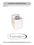
3. Dimension
YHUJYH028BAR-A-X
YHUJYH036BAR-A-X
YHUJYH048BAR-A-X
YHUJYH048BAS-A-X
1008
25
25
840
830
948
648
410
447
340
380
580
180
YHUJYH060BAS-A-X
33
180
YHUJYH024BAR-A-X
Model
YHUJYH024BAR-A-X
W
D
H
L1
L2
L3
860
308
730
633
113.5
340
34
Cassette
wx~vn3QUXUZS [\QZUZSo
wv}v n4U_`MZOQ NQ`cQQZ
_a_\QZPUZS N[X`_o
{w{
}~v n4U_`MZOQ NQ`cQQZ
_a_\QZPUZS N[X`_o
BQR^USQ^MZ` \U\Q
Ca_\QZPUZS N[X`_
}~vn4U_`MZOQ NQ`cQQZ
_a_\QZPUZS N[X`_o
~zvn9ZP[[^ aZU`o
~|vn3QUXUZS [\QZUZSo
_a_\QZPUZS N[X`_o
|v;
}~v n4U_`MZOQ NQ`cQQZ
~zvn9ZP[[^ aZU`o
~*vn3QUXUZS [\QZUZSo
*{vn?^ZMYQZ` \MZQXo
xz; x~;
{w{
~*vn3QUXUZS [\QZUZSo
*{vn?^ZMYQZ` \MZQXo
xv ?bQ^
>[`Q+
4UYQZ_U[Z [R OQUXUZS [\QZUZS YM^WQP cU`T p OMZ
NQ M_ XM^SQ M_ *wvYYr Na` `TQ YM`OTUZS \M^` [R
OQUXUZS cU`T [^ZMYQZ` \MZQX _TMXX NQ [bQ^ xvYYt
yvv
yv wzv
Ca_\QZPUZS N^MOWQ`
3QUXUZS
y|; z~;
w{
vv
~|vs~*v nOQUXUZS T[XQo
*{v
[b
Q^
w{
vv
}*v
~|vs~*v
*{v
[b
Q^
w{
vv
y{
NQX[c yvvv
[bQ^ wvvv
2M^^UQ^
7^[aZP
35
w{v
wyz
y{
|v
w|z
wz*
~~
~{
yz|
y{
~zv
y{
wz*
x~}
~zv
yz|
GMXX [^ NM^^UQ^
[b
Q^
|*v n8MZSUZS \[_U`U[Zo
[b
Q^
w{
vv
YHFJZH012BAM-AFX
YHFJZH018BAM-AFX
YHFJZH024BAR-AFX
1-+
1+0
1++
22+
,++
100
/+
.0
.0
.+
-++
33+
36
-/+
,33
3++
YHFJZH048BAS-AFX YHFJZH060BAS-AFX
(mm)
1580
700
598
495
285
36
114
55
240
570
640
90
D=25
D = 47
440 300
150
D=200
D = 47
D = 47
D = 47
95
40
60
? 50
? 200
? 47
224
? 47
? 47
155
? 47
90
37
Low ESP duct
B
D
I
E
G
H
F
Indoor unit dimensions(unit:mm)
Unit model
A
B
C
12K
420
892
370
18K 24K
420
1212
370
D
C
A
12K
18K
24K
E
F
850
185
640
1170
185
960
G
H
I
85
760
152
85
1080 152
Med ESP duct
YHEJXH024BAR--GX
38
YHEJXH028/36/48BAR--GX
4
758
15.88
2
YHGJXH048/60BAR--GX
1105
270
250
365
185
170
60
800
830
1320
39
45
250
1200
4. Piping and wiring installation
outdoor unit
Carefully read the following information in order to operate the air conditioner correctly.
Below are listed three kinds of Safety Precautions and Suggestions.
WARNING Incorrect operations may result in severe consequences of death or serious injuries.
CAUTION Incorrect operations may result in injuries or machine damages; in some cases may
cause serious consequences.
INSTRUCTIONS: These information can ensure the correct operation of the machine.
Symbols used in the illustrations
:Indicates an action that must be avoided.
! :Indicates that important instructions must be followed.
:Indicates a part which must be grounded.
:Beware of electric shock (This symbol is displayed on the main unit label.)
After reading this handbook, hand it over to those who will be using the unit.
The user of the unit should keep this mamual at hand and make it available to those who will be performing repairs or
relocating the unit. Also, make it available to the new user when the user changes hands.
Be sure to conform with the following important Safety Precautions.
WARNING
If any abnormal phenomena is found
(e. g.smell of firing), please cut off
switch off
the power supply immediately, and
contact the dealer to find out the
handling method.
In such case, to continue using the conditioner will damage
the conditioner, and may cause electrical shock or fire
hazard.
After a long time use of air-conditioner
the base should be checked for any
damages.
If the damaged base is not repaired, the
unit may fall down and cause accidents.
Don't dismantle the outlet of the
outdoor unit.
The exposure of fan is very dangerous
which may harm human beings.
When need maintenance and repairment,
call dealer to handle it.
Incorrect maintenance and repairment
may cause water leak, electrical shock
and fire hazard.
WARNING
No goods or nobody is permitted to
placed on or stand on outdoor unit.The
falling of goods and people may cause
accidents.
Air-conditioner can't be installed in the environment with
inflammable gases because the inflammable gases near
air-conditioner may cause fire hazard.
Please let the dealer be responsible for installing the
conditioner. Incorrect installation may cause water leak,
electrical shock and fire hazard.
Don't operate the air-conditioner with
damp hands.Otherwise it will be shocked.
Call the dealer to take measures to prevent the refrigerant
from leaking.
If conditioner is installed in a small room, be sure to take
every measure in order to prevent suffocation accident
even in case of refrigerant leakage.
Only use correctly-typed fuse.
May not use wire or any other materials
replacing fuse, otherwise it may cause
faults or fire accidents.
Use discharge pipe correctly to ensure efficient discharge.
Incorrect pipe use may cause water leaking.
Installed electrical-leaking circuit breaker.
It easily cause electrical shock without circuit breaker.
40
When conditioner is installed or reinstalled, the dealer should
be responsible for them.
Incorrect installation may cause water leaking, electrical
shock and fire hazard.
Connect earthing wire.
Earthing wire should not be connected to the gas
pipe, water pipe, lightning rod or phone line,
incorrect earthing may cause shock.
Earthing
Safety Precautions
WARNING
Have the unit professionally installed.
Improper installation by an unqualified person may result
in water leak, electric shock, or fire.
Place the unit on a stable, level surface that withstands the
weight of the unit to prevent the unit from tipping over or
falling causing injury as a result.
Only use specified cables for wiring. Securely connect each
cable, and make sure that the cables are not straining the
terminals.
Cables not connected securely and properly may generate
heat and cause fire.
Be sure to carefully follow each step in this handbook when
installing the unit.
Improper installation may result in water leak, electric shock,
smoke or fire.
Have all electrical work performed by a licensed electrician
according to the local regulations and the instructions given
in this manual. Secure a circuit designated exclusively to
the unit.
Improper installation or a lack of circuit capacity may cause
the unit to malfunction or present a risk of electric shock,
smoke,and fire.
Take necessary safety measures against typhoons and
earthquakes to prevent the unit from falling over.
Securely attach the terminal cover(panel) on the unit.
If installed improperly, dust and/or water may enter the unit
and present a risk of electric shock, smoke or fire.
Do not make any changes or modifications to the unit. In
case of problems, consult the dealer.
If repairs are not made properly, the unit may leak water
and present a risk of electric shock, or it may produce smoke
or cause fire.
Only use refrigerant R410A as indicated on the unit when
installing or relocating the unit.
The use of any other refrigerant or an introduction of air into
the unit circuit may cause the unit to run an abnormal cycle
and abnormal cycle and cause the unit to burst.
WARNING
Do not touch the fins on the heat exchanger with bare hands,
for they are sharp and dangerous.
In the event of a refrigerant gas leak, provide adequate
ventilation to the room.
If leaked refrigerant gas is exposed to a heat source, noxious
gases may form.
With All-Fresh type air conditioners, outdoor air may be
directly blown into the room upon thermo off. Take this into
consideration when installing the unit.
Direct exposure to outdoor air may present a health hazard,
and it may also cause food items to deteriorate.
Do not try to defeat the safety features of the devices, and
do not change the settings.
Defeating the safety features on the unit such as the pressure
switch and temperature switch or using parts other than the
dealer or specialist may result in fire or explosion.
This appliance is not intended for use by persons (including
children) with reducedphysical, sensory or mental capabilities,
or lack of experience and knowledge, unless they have been
given supervision or instruction concerning use of the
appliance by a person responsible for their safety.
41
When installing the unit in a small room, safeguard against
hypoxia that results from leaked refrigerant reaching the
threshold level.
Consult the dealer for necessary measures to take.
When relocating the air conditioner, consult the dealer or
a specialist.
Improper installation may result in water leak, electric shock,
or fire.
After completing the service work, check for a refrigerant
gas leak.
If leaked gas refrigerant is exposed to a heat source such
as fan heater,stove,and electric grill, noxious gases may
form.
Only use specified parts.
Have the unit professionally installed. Improper installation
may cause water leak, electric shock,smoke, or fire.
Children should be supervised to ensure that they do not
play with the appliance.
Safety Precautions
Precautions for Handling Units for Use with R410A
Caution
Do not use the existing refrigerant piping
Use a vacuum pump with a reverse-flow check valve.
If other types of valves are used, the vacuum pump oil will
The old refrigerant and refrigerator oil in the existing piping
flow back into the refrigerant cycle and cause the refrigerator
contain a large amount of chlorine, which will cause the
oil to deteriorate.
refrigerator oil in the new unit to deteriorate.
R410A is a high-pressure refrigerant, and the use of the
Do not use the following tools that have been used with the
existing piping may result in bursting.
conventional refrigerants. Prepare tools that are for exclusive
use with R410A.
(Gauge manifold, charging hose, gas leak detector,
reverse-flow check valve, refrigerant charge base,vacuum
gauge, and refrigerant recovery equipment.)
If refrigerant and/or refrigerant oil left on these tools are
Keep the inner and outer surfaces of the pipes clean and
mixed in with R410, or if water is mixed with R410A, it will
free of contaminants such as sulfur, oxides, dust/dirt shaving
cause the refrigerant to deteriorate.
particles,oils,and moisture.
Since R410A does not contain chlorine, gas-leak detectors
Contaminants inside the refrigerant piping will cause the
for conventional refrigerators will not work.
refrigerant oil to deteriorate.
Caution
Store the piping to be used during installation indoors, and Do not use a charging cylinder.
keep both ends of the piping sealed until immediately before
The use of charging cylinder will change the composition
brazing.(keep elbows and other joints wrapped in plastic.)
of the refrigerant and lead to power loss.
If dust, dirt, or water enters the refrigerant cycle, it may
cause the oil in the unit to deteriorate or may cause the
compressor to malfunction.
Exercise special care when handling the tools.
An introduction of foreign objects such as dust, dirt or
Use a small amount of ester oil, ether oil, or alkylbenzene
water into the refrigerant cycle will cause the refrigerating
to coat flares and flange connections.
machine oil to deteriorate.
A large amount of mineral oil will cause the refrigerating
machine oil to deteriorate.
Use liquid refrigerant to charge the system.
Charge the unit with gas refrigerant will cause the refrigerant Only use R410A refrigerant.
in the cylinder to change its composition and will lead to
The use of refrigerants containing chlorine(i.e. R22) will
a drop in performance
cause the refrigerant to deteriorate.
Before Installing the Unit
Caution
Do not install the unit in a place where there is a possibility When installing the unit in a hospital, take necessary measures
of flammable gas leak.
against noise.
Leaked gas accumulated around the unit may start a fire.
High-frequency medical equipment may interfere with the
normal operation of the air conditioning unit or the air
Do not use the unit to preserve food, animals, plants, artifacts,
conditioning unit may interfere with the normal operation
or for other special purposes.
of the medical equipment
The unit is not designed to provide adepuate conditions
to preserve the quality of these items.
Do not use the unit in an unusual environment
The use of the unit in the presence of a large amount of
oil, steam, acid, alkaline solvents or special types of sprays
Do not place the unit on or over things that may not get wet.
may lead to a remarkable drop in performance and/or
When humidity level exceeds 80% or when the drainage
malfunction and presents a risk of electric shock, smoke,
system is clogged, indoor units may drip water.
or fire.
Installation of a centralized drainage system for the outdoor
The presence of organic solvents, corroded gas (such as
unit may also need to be considered to prevent water drips
ammonia,sulfur compounds,and acid may cause gas or
from the outdoor units.
water leak.)
42
Safety Precautions
Before Installing (Relocating) the Unit or Performing Electric Work
Caution
Ground the unit.
Do not connect the grounding on the unit to gas pipes,water
pipes, lightning rods, or the grounding terminals of
telephones. Improper grounding presents a risk of electric
shock, smoke, fire, or the noise caused by improper
grounding may cause the unit to malfunction.
Do not spray water on the air conditioners or immerse the
air conditioners in water.
Water on the unit presents a risk of electric shock.
Periodically check the platform on which is placed for damage
to prevent the unit from falling.
If the unit is left on a damaged plarform, it may topple over,
causing injury.
Make sure the wires are not subject to tension.
If the wires are too taut, they may break or generate heat
When installing draining pipes, follow the instructions in the
and/or smoke and cause fire.
manual, and make sure that they properly drain water so as
Install a breaker for current leakage at the power source
to avoid dew condensation.
to avoid the risk of electric shock.
If not installed properly, they may cause water leaks and
Without a breaker for current leakage, there is a risk of
damage the furnishings.
electric shock, smoke or fire.
Properly dispose of the packing materials.
Use breakers and fuses (electrical current breaker, remote
Things such as nails may be included in the package.
switch<switch+Type-B fuse>,molded case circuit breaker)
Dispose of them properly to prevent injury.
with a proper current capacity.
Plastic bags present a choking hazard to children. Tear
up the plastic bags before disposing of them to prevent
The use of large-capacity fuses, steel wire, or copper wire
accidents.
may damage the unit or cause smoke or fire.
Before the Test Run
Caution
Do not operate switches with wet hands to avoid electric.
Do not touch the refrigerant pipes with bare hands during
and immediately after operation.
Depending on the state of the refrigerant in the system,
certain parts of the unit such as the pipes and compressor
may become very cold or hot and may subject the person
to frost bites or burning.
Do not operated the unit without panels and safety guards
in their proper places.
They are there to keep the users from injury from
accidentally touching rotating, high-tempreture or highvoltage parts.
Do not turn off the power immediately after stopping the unit.
Allow for at least five minutes before turning off the unit,
otherwise the unit may leak water or experience other
problems.
Do not operate the unit without air filters.
Dust particles in the air may clog the system and cause
malfunction.
43
Read Before Installation
Items to Be Checked
(1). Verify the type of refrigerant used by the unit to be serviced. Refrigerant Type: R410A
(2). Check the symptom exhibited by the unit to be serviced. Look in this service handbook for symptoms relating to the
refrigerant cycle.
(3). Be sure to carefully read the safety precautions at the beginning of this document.
(4). If there is a gas leak or if the remaining refrigerant is exposed to an open flame, a noxious gas hydrofluoric acid may
form. Keep workplace well ventilated.
CAUTION
Install new pipes immediately after removing old ones to keep moisture out of the refrigerant circuit.
Chloride in some types of refrigerants such as R22 will cause the refrigerating machine oil to deteriorate.
Necessary Tools and Materials
Prepare the following tools and materials necessary for installing and servicing the unit.
Necessary tools for use with R410A(Adaptability of tools that are for use with R22 and R407C).
1. To be used exclusively with R410A ( Not to be used if used with R22 or R407C )
Tools/Materials
Use
Notes
Gauge Manifold
Evacuating,refrigerant charging
5.09MPa on the High-pressure side.
Charging Hose
Evacuating, refrigerant charging
Hose diameter larger than the concentional ones.
Refrigerant Recovery Equipment
Refrigerant recovery
Refrigerant Cylinder
Refrigerant charging
Write down the refrigerant type. Pink in color at the top of the cylinder.
Refrigerant Cylinder Charging Port
Refrigerant charging
Hose diameter larger than the conventional ones.
Flare Nut
Connecting the unit to piping
Use Type-2 Flare nuts.
2. Tools and materials that may be used with R410 with some restrictions
Tools/Materials
Use
Notes
Gas leak detector
Detection of gas leaks
The ones for HFC type refrigerant may be used.
Vacuum Pump
Vacuum drying
May be used if a reverse flow check adaptor is attached.
Flare Tool
Flare machining of piping
Chages have been made in the flare machining dimension.Refer to the next page.
Refrigerant Recovery Equipment
Recovery of refrigerant
May be used if designed for use with R410A.
3. Tools and materials that are used with R22 or R407C that can also be used with R410A
Tools/Materials
Use
Vacuum Pump with a Check Valve
Vacuum drying
Bender
Bending pipes
Torque Wrench
Tightening flare nuts
Pipe Cutter
Cutting pipes
Welder and Nitrogen Cylinder
Welding pipes
Refrigerant Charging Meter
Refrigerant charging
Vacuum Gauze
Checking vacuum degree
Notes
Only
12.70 (1/2'') and
15.88(5/8'') have a larger flare machining dimension.
4. Tool and materials that must not used with R410A
Tools/Materials
Charging Cylinder
Use
Notes
Refrigerant Charging
Must not be used with R410-type units.
Tools for R410A must be handled with special care, and keep moisture and dust from entering the cycle.
44
Read Before Installation
Piping Materials
Types of Copper Pipes (Reference)
Maximum Operation Pressure
Applicable Refrigerants
3.4MPa
R22, R407C
4.15MPa
R410A
Use pipes that meet the local standards.
Piping Materials/Radial Thickness
Use pipes made of phosphorus deoxidized copper.
Since the operation pressure of the units that use R410A is higher than that of the units for use with R22, use pipes with
at least the radial thickness specified in the chart below. (Pipes with a radial thickness of 0.7mm or less may not be used.)
Size(mm)
6.35
Size(inch)
1/4''
Radial Thickness(mm)
0.8t
9.52
3/8''
0.8t
12.7
1/2''
0.8t
15.88
5/8''
1.0t
19.05
3/4''
1.0t
Type
Type-O pipes
Type-1/2H or Hpipes
Although it was possible to use type-O for pipes with a size of up to 19.05(3/4") with conventional refrigerants, use type1/2H pipes for units that use R410A.(Type-O pipes may be used if the pipe size is 19.05 and the radial thickness is 1.2t.)
The table shows the standards in Japan. Using this table as a reference, choose pipes that meet the local standards.
Flare Machining (type-O and OL only)
The flare machining dimensions for units that use R410A is larger than those for units that use R22 in order to increase
air tightness.
Flare Machining Dimension(mm)
Size
Dimension A
R410A
R22
6.35
1/4"
9.1
9.0
9.52
3/8"
13.2
13.0
12.7
1/2"
16.6
16.2
15.88
5/8"
19.7
19.4
19.05
3/4"
24.0
23.3
Dimension A
External dimension of pipes
If a clutch type flare tool is used to machine flares on units that use R410A, make the protruding part of the pipe between
1.0 and 1.5mm. Copper pipe gauge for adjusting the length of pipe protrusion is useful.
Flare Nut
Type-2 flare nuts instead of type-1 nuts are used to increase the strength. The size of some of the flare nuts have also
been changed.
Flare nut dimension(mm)
External dimension of pipes
Size
Dimension B
R410A(Type2)
R22(Type1)
17.0
17.0
3/8"
22.0
22.0
1/2"
26.0
24.0
15.88
5/8"
29.0
27.0
19.05
3/4"
36.0
36.0
6.35
1/4"
9.52
12.7
Dimension B
The table shows the standards in Japan. Using this table as a reference, choose pipes that meet the local standards.
45
Read Before Installation
Air Tightness Test
No changes from the conventional method. Note that a refrigerant leakage detector for R22 or R407C cannot detect R410A
leakage.
NO
NO
Halide torch
R22 or R407C leakage detector
Items to be strictly observed :
1.Pressurize the equipment with nitrogen up to the design pressure and then judge the equipment's air tightness, taking
temperature variations into account.
2.When investigating leakage locations using a refrigerant, be sure to use R410A.
3.Ensure that R410A is in a liquid state when charging.
Reasons:
Use of oxygen as the pressurized gas may cause an explosion.
1.
2.
Charging with R410A gas will lead the composition of the remaining refrigerant in the cylinder to change and then this
refrigerant can not be used.
Vacuuming
1.Vacuum pump with check valve
A vacuum pump with a check valve is required to prevent the vacuum pump oil from flowing back into the refrigerant
circuit when the vacuum pump power is turned off (power failure). It is also possible to attach a check valve to the actual
vacuum pump afterwards.
2.Standard degree of vacuum for the vacuum pump
Use a pump which reaches 65Pa or below after 5 minutes of operation.
In addition, be sure to use a vacuum pump that has been properly maintained and oiled using the specified oil. If the
vacuum pump is not properly maintained, the degree of vacuum may be too low.
3.Required accuracy of the vacuum gauge
Use a vacuum gauge that can measure up to 650Pa. Do not use a general gauge manifold since it cannot measure a
vacuum of 650Pa.
4.Evacuating time
Evacuate the equipment for 1 hour after 650Pa has been reached.
After envacuating, leave the equipment for 1 hour and make sure the that vacuum is not lost.
5.Operating procedure when the vacuum pump is stopped
In order to prevent a backflow of the vacuum pump oil, open the relief valve on the vacuum pump side or loosen the
charge hose to drawn in air before stopping operation.The same operating procedure should be used when using a
vacuum pump with a check valve.
Charging Refrigerant
R410A must be in a liquid state when charging.
Reasons:
R410A is a pseudo-azeotropic refrigerant (boiling point R32= -52 C, R125= -49 C) and can roughly be handled in the same
way as R22; however, be sure to fill the refrigerant from the liquid side, for doing so from the gas side will somewhat change
the composition of the refrigerant in the cylinder.
Note
In the case of a cylinder with a syphon, liquid R410A is charged without turning the cylinder up side down. Check the
type of cylinder before charging.
Remedies to be taken in case of a refrigerant leak
When refrigerant leaks, additional refrigerant may be charged. (Add the refrigerant from the liquid side)
Characteristics of the Conventional and the New Refrigerants
Because R410A is a simulated azeotropic refrigerant, it can be handled in almost the same mammer as a single refrigerant
such as R22. Howerver, if the refrigerant is removed in the vapor phase, the composition of the refrigerant in the cylinder
will somewhat change.
Remove the refrigerant in the liquid phase. Additional refrigerant may be added in case of a refrigerant leak.
46
Name of Parts
24K
28K 36K
Air inlet
Air inlet
Air outlet
Air outlet
Compressor
(Inside of unit)
Compressor
(Inside of unit)
60K
48K(1 phase) 48K(3 phase)
Air inlet
Air inlet
Air outlet
Air outlet
Compressor
(Inside of unit)
Compressor
(Inside of unit)
47
Installation Procedure
Installation of Outdoor Unit
1. Selection of the place of installation
Select the place of installation satisfying the following conditions and, at the same time, obtain a consent from the client or
user.
Place where air circulates.
Place free from heat radiation from other heat sources.
Place where drain water may be discharged.
Place where noise and hot air may not disturb the neighborhood.
Place where there is not heavy snowfall in the winter time.
Place where obstacles do not exist near the air inlet and air outlet .
Place where the air outlet may not be exposed to a strong wind.
Place surrounded at four sides are not suitable for installation. A 1m or more of overhead space is needed for the unit.
Avoid mounting guide-louvers to the place where short-circuit is a possibility.
When installing several units, secure sufficient suction space to avoid short circuiting.
Open space requirement around the unit
Air inlet
L2
Air inlet
Distance
L1
L2
L3
L3
500
(Servicing
space)
Case I
open
300 mm
150 mm
Case II
open
300 mm
300 mm
Case III
500 mm
open
150 mm
Note :
(1) Fix the parts with screws.
(2) Don't intake the strong wind directly to
NO
the outlet air-flow hole.
(3) A one meter distance should be
Wind direction
kept from the unit top.
(4) Don't block the surroundings of the unit with sundries.
(5) If the outdoor unit is installed in a place that is exposed
to the wind, install the unit so that the outlet grid is NOT
pointing in the direction of the wind.
Air outlet
L1
2. Installation of outdoor unit
Fix the unit on the foundation in a proper way according to the condition of the installation place, referring to the following
information.
Give enough room for the concrete foundation to fix by anchor bolts.
Place the concrete foundation deep enough.
Install the unit so that the angle of inclination must be less than 3 degrees.
(a) Concrete foundation
(b) Foundation anchor
Unit
Unit
Anchor bolt
Concrete foundation
Concrete foundation
To fix by bolts
Anchor bolt
48
Installation Procedure
Installation of Outdoor Unit
3. Installation dimension (Unit:mm)
24K
28K 36K
948
25
730
840
860
633
380
340
308
340
580
60K
48K(1 phase) 48K(3 phase)
948
25
1250
830
1008
25
648
180
49
340
180
380
447
410
580
Installation Procedure
Piping Connection
1. Piping diagram
24K 28K 36K 48K(1 phase) 48K(3 phase) 60K
Flare connection
3-way stop valve
Gas pipe
Indoor
unit
Outdoor
unit
Liquid
pipe
3-way stop valve
2. Piping size
24K 28K 36K
48K(1 phase) 48K(3 phase)
60K
Liquid pipe
9.52x0.8mm
Gas pipe
15.88x1.0mm
Liquid pipe
9.52x0.8mm
Gas pipe
19.05x1.0mm
90+0.5
Install the removed flare nuts to the pipes
to be connected, then flare the pipes.
3. Limitations for one way piping length and vertical height difference
Model
One way piping length
Vertical height difference
(between indoor and outdoor)
24K 28K 36K
less than 30 m
less than 20 m
48K(1 phase) 48K(3 phase) 60K
less than 50 m
less than 30 m
Precautions for refrigerant piping
Do not twist or crush piping.
Be sure that no dust is mixed in piping.
Bend piping with as wide angle as possible.
Keep insulating both gas and liquid piping.
Check flare-connected area for gas leakage.
Spanner
Joint
Spanner
Nut
4. Piping connection method
Apply refrigerant oil to the joint and the flange.
To bend a pipe, give the roundness as possible not to crush
the pipe.
When connecting pipe, hold the pipe centre to centre and then
screw nut on by hand, refer to Fig.
Be careful not to let foreign matters, such as sands enter
the pipe.
Pipe diameter
Liquid pipe 6.35mm
14.2-17.2
Liquid pipe 9.52mm
32.7-39.9
Gas pipe 12.7mm
49.5-60.3
Gas pipe 15.88mm
61.8-75.4
Gas pipe 19.05mm
97.2-118.6
Forced fastening without centering may damage the threads and cause a gas leakage.
50
Fastening torque (N.m)
Installation Procedure
Air Tightness Test
After finishing connection of refrigerant pipe, it shall perform air tightness test.
The air tightness test adopts nitrogen tank to give pressure according to the pipe connection mode as the following figure
shown.
The gas and liquid valve are all in close state. In order to prevent the nitrogen entering the circulation system of outdoor
unit, tighten the valve rod before giving pressure (both gas and liquid valve rods).
Low pressure piezometer
High pressure piezometer
Indoor
Outdoor
stop valve totally closed
(Gas side)
Completely tightened
Flare part
VL VH
Meter separator
Discharging valve
Completely tightened
Flare part
Manhole
Indoor units
Dropping valve
Nitrogen tank
Outdoor units
stop valve totally closed
(Liquid side)
2
Line pressure gauge
1) Pressurize for over 3 minutes at 0.3MPa (3.0 kg/cm g).
2
2) Pressurize for over 3 minutes at 1.5MPa (15 kg/cm g). A large
leakage will be found.
2
3) Pressurize for about 24 hours at 3.0MPa (30 kg/cm g). A small
leakage will be found.
Cylinder pressure gauge
Tubing bring brazed
Sweat joint
Cylinder of nitrogern
Large slip-on connector
Service hose
Check if the pressure drops
If the pressure does not drop, then pass.
If the pressure drops, then please check the leaking point.
2
When pressurizing for 24 hours, a variation of 1 C in the ambient temperature will cause a variation of 0.01MPa(0.1kg/cm g)
in pressure. It shall be corrected during test.
Checking the leaking point
In 1) to 3) steps, if the pressure drops, check the leakage in each joint by listening, touching and using soap water etc.
to identify the leaking point. After confirming the leaking point, welding it again or tighten the nut tightly again.
Installation Procedure
Additional Refrigerant Charge
When the total length (L) of the two indoor units' connecting pipe is less than 5m, it is unnecessary to charge additional
refrigerant.
If the connecting pipe (L) exceeds 5m, it shall charge M(g) additional refrigerant per meter.
That is: Refrigerant charging amount = (L-5m) x 45 (g/m)
Only in COOLING operation can charge the additional refrigerant.
When charging, the refrigerant shall be charged from the charging nozzle of low pressure valve.
Be carefull when charging refrigerant, do not let the air mix into the system, and must charge the additional refrigerant
in liquid state.
51
Installation Procedure
Vacuuming
Piping vavuum method: to use vacuum pump
Liquid stop valve
Gas stop valve
1. Detach the service port's cap of gas stop valve, the valve rod's cap for liquid
stop valve and gas stop valve, and connect the service port into the projection
of charge hose (low) for gaugemanifold. Then connect the projection of
charge hose (center) for gaugemanifold into vacuum pump.
Gauge manifold(R410A)
Vacuum pump(R410A)
2. Open the handle at low in gaugemanifold, and operate vacuum pump. If the
scale-moves of gause (low) reach vacuum condition in a moment, check
the step 1 again.
3. Vacuumize for over 15min. And check the level gauge which should read 0.1MPa (-76 cm Hg) at low pressure side. After the completion of vacuumizing,
close the handle 'Lo' in the vacuum pump. Check the condition of the scale
and hold it for 1-2min. If the scale-moves back in spite of tightening, make
flaring work again, then return to the beginning of the step 3.
4. Open the valve rod for the liquid stop valve to an angle of anticlockwise 90
degree. After 6 seconds, close the liquid stop valve and make the inspection
of gas leakge.
Open
Close
Liquid stop valve
90
Gas stop valve
Service port
90 for 6 sec.
5. No gas leakage? In case of gas leakage, tighten parts of pipe connection. If leakage stops, then proceed the step 6. If it
does not stop gas leakage, discharge whole refrigerants from the service port. After flaring work again and vacuumize,
fill up prescribed refrigerant from the gas cylinder.
6. Detach the charge hose from the service port, open liquid stop valve and
gas stop valve. Turn the valve rod anticlockwise until hitting lightly.
7. To prevent the gas leakage, turn the service ports cap, the valve rodis cap
for liquid stop valve and gas stop valve a little more than the point where
the torque increases suddenly.
Liquid stop valve
Gas stop valve
Valve rod cap
Valve rod cap
Service port cap
CAUTION:
If the refrigerant of the air conditioner leaks, it is necessary to make all the refrigerant out. Vacuumize first, then charge
the liquid refrigerant into air conditioner according to the amount marked on the nameplate.
52
Installation Procedure
Electrical Wiring
WARNING!
DANGER OF BODILY INJURY OR DEATH
TURN OFF ELECTRIC POWER AT CIRCUIT BREAKER OR POWER SOURCE BEFORE MAKING ANY ELECTRIC
CONNECTIONS.
GROUND CONNECTIONS MUST BE COMPLETED BEFORE MAKING LINE VOLTAGE CONNECTIONS.
Precautions for Electrical wiring
Electrical wiring work should be conducted only by authorized personnel.
Do not connect more than three wires to the terminal block. Always use round type crimped terminal lugs with insulated
grip on the ends of the wires.
Use copper conductor only.
Selection of size of power supply and interconnecting wires
Select wire sizes and circuit protection from table below. (This table shows 20 m length wires with less than 2% voltage
drop.)
Phase
Switch breaker
(A)
Overcurrent protector
rated capacity (A)
Power source
wire size
(minimum)
(mm2)
24K
1
40
26
6.0
40
30
28K
36K
48K(1 phase)
1
40
30
6.0
40
30
3
30
20
4.0
30
30
Item
Model
48K(3 phase)
60K
Circuit breaker
Earth leakage breaker
Switch
breaker(A)
Leak
current(mA)
If the supply cord is damaged, it must be replaced by the manufacturer or itsservice agent or a similar qualified person.
If the fuse of control box is broken, please change it with the type of T25A/450VAC;
If the fuse of control PC board is broken, please change it with the type of T3.15A/250VAC. But for 28K,36K,48K(1
phase),48K(3 phase),60K, the type is T6.3A/250VAC.
The wiring method should be in line with the local wiring standard.
The power cable and connecting cable should be self-provided.
All the cables shall have got the European authentication certificate. During installation, when the connecting cables
break off, it must be assured that the grouding wire is the last one to be broken off.
The breaker of the air conditioner should be all-pole switch; and the distance between its two contacts should not be no
less than 3mm. Such means for disconnection must be incorporation in the fixed wiring.
The distance between its two terminal blocks of indoor unit and outdoor unit should not be over 5m. If exceeded, the
diameter of the wire should be enlarged according to the local wiring standard.
A leakage breaker must be installed.
The specification of power cable
For models 28K,36K,48K(1 phase), the power cable should be H05RN-F 3G 6.0mm2.
For models 48K(3 phase), 60K,the power cable should be H07RN-F 5G 4.0mm2.
53
Installation Procedure
Electrical Wiring
Wiring procedure
1) Remove set screws on the side before taking off the front panel toward the direction.
2) Connect wires to the terminal block correctly and fix the wires with a wire clamp equipped nearby the terminal block.
3) Route the wires in a proper way and penetrate the wires through the opening for electrical wiring on the side panel.
WARNING:
INTERCONNECTING WIRES MUST BE WIRED ACCORDING TO FIGURE BELOW. INCORRECT WIRING MAY CAUSE
EQUIPMENT DAMAGE.
24K 28K 36K 48K(1 phase)
To indoor unit
L
N
1
2
3
Y/G
Power supply :1PH,220-230V~,50/60Hz
Outdoor unit
terminal block
48K(3 phase) 60K
Indoor unit
terminal block
Outdoor unit
R S
terminal block
T N
1
2
3
Y/G
1
2
3
Y/G
Power supply:380-400V, 3N~,50/60Hz
54
Cassette D_cdS]]Sd[`_ Ib`UWVebW
1 =@AHJ@ DGKL<EE<LDHG -4[Zm` PU_OM^P MZe MOOQ__[^UQ_ aZ`UX O[Y\/
4Q`Q^YUZQ `TQ cMe `[ OM^^e aZU` `[ UZ_`MXXM`U[Z \XMOQt
4[Zm` ^QY[bQ \MOWUZS aZ`UX aZU` ^QMOTQ_ UZ_`MXXM`U[Z \XMOQt
9R aZ\MOWUZS U_ aZWMb[UPMNXQr \^[`QO` aZU` \^[\Q^Xet
2 K@E@>LDHG HA DGKL<EE<LDHG IE<>@
nwo 9Z_`MXXM`U[Z \XMOQ _TMXX YQQ` `TQ R[XX[cUZS MZP MS^QQP Ne Oa_`[YQ^_+
@XMOQ cTQ^Q \^[\Q^ MU^ RX[c OMZ NQ QZ_a^QPt
>[ NX[OW `[ MU^ RX[ct
GM`Q^ P^MUZMSQ U_ _Y\[`Tt
@XMOQ _`^[ZS QZ[aST `[ _a\\[^` aZU` cQUST`t
@XMOQ cTQ^Q UZOXUZM`U[Z U_ Z[` QbUPQZ` [Z OQUXUZSt
5Z[aST _\MOQ R[^ YMUZQZMZOQt
9ZP[[^ MZP [a`P[[^ aZU` \U\UZS XQZS`T U_ cU`TUZ XUYU`t nBQRQ^ `[ 9Z_`MXXM`U[Z =MZaMX R[^ [a`P[[^ aZU`to
9ZP[[^ MZP [a`P[[^ aZU`r \[cQ^ OMNXQr UZ`Q^ aZU` OMNXQ M^Q M` XQM_` w Y McMe R^[YDtFt ^MP[\t DTU_ U_ TQX\RaX `[ Mb[UP
\UO`a^Q PU_`a^NMZOQ MZP Z[U_Qt n5bQZ UR w Y U_WQ\`r Z[U_Q OMZ _`UXX M\\QM^ UR ^MPU[ cMbQ U_ _`^[ZSo
nxo 3QUXUZS TQUST`
9ZP[[^ aZU` OMZ NQ UZ_`MXXQP [Z OQUXUZS [R xt{syY UZ TQUST`t nBQRQ^ `[ 6[QXP _Q``UZS MZP 9Z_`MXXM`U[Z =MZaMX [R [^ZMYQZ`
\MZQXto
nyo 9Z_`MXX _a_\QZPUZS N[X`t
3TQOW UR `TQ UZ_`MXXM`U[Z \XMOQ U_ _`^[ZS QZ[aST `[ T[XP cQUST`t DMWQ ZQOQ__M^e YQM_a^Q_ UZ OM_Q U` U_ Z[` _MRQt
n4U_`MZOQ NQ`cQQZ T[XQ_ M^Q YM^WQP [Z \M\Q^ \M``Q^Zt BQRQ^ `[ \M\Q^ \M``Q^Z R[^ \XMOQ ZQQP NQ ^QUZR[^OQPo
9Z_`MXXM`U[Z _\MOQ
ywv
xz; x~;
yvv
1U^ [a`XQ`
w{vv ?bQ^
x{vv ?bQ^
wx; w~; y|; z~; |v;
8
8
=[PQX
1U^ UZXQ`
1U^ [a`XQ`
w{vv ?bQ^
3 IJ@I<J<LDHG AHJ LC@ DGKL<EE<LDHG
nwo @[_U`U[Z [R OQUXUZS [\QZUZS NQ`cQQZ aZU` MZP _a_\QZPUZS N[X`t
wx; w~;
_a_\QZPUZS N[X`_o
~zvn9ZP[[^ aZU`o
}~v n4U_`MZOQ NQ`cQQZ
~*vn3QUXUZS [\QZUZSo
*{vn?^ZMYQZ` \MZQXo
?^ZMYQZ` \MZQX }vvYY
9ZP[[^ aZU` {}vYY
3QUXUZS [\QZUZS |{vYY
xz; x~;
BQR^USQ^MZ` \U\Q
Ca_\QZPUZS N[X`_
}~vn4U_`MZOQ NQ`cQQZ
_a_\QZPUZS N[X`_o
~zvn9ZP[[^ aZU`o
4U_`MZOQ NQ`cQQZ
_a_\QZPUZS N[X`_ {y{YY
9ZP[[^ aZU` {}vYY
~*vn3QUXUZS [\QZUZSo
*{vn?^ZMYQZ` \MZQXo
3QUXUZS [\QZUZS |{vYY
?^ZMYQZ` \MZQX }vvYY
Ca_\QZPUZS N[X`_
3QUXUZS
?^ZMYQZ` \MZQX
3QUXUZS
55
yvv
ywv
yv wzv
Ca_\QZPUZS N^MOWQ`
yv
w{v
?bQ^XM\ NQ`cQQZ OQUXUZS MZP
[^ZMYQZ` \MZQX _TMXX NQ x{YY
D_cdS]]Sd[`_ Ib`UWVebW
y|; z~;
w{
vv
~|vs~*v nOQUXUZS T[XQo
*{v
[b
Q^
w{
vv
}*v
[b
Q^
w{
vv
~|vs~*v
*{v
[b
Q^
w{
vv
y{
w{v
y{
NQX[c yvvv
[bQ^ wvvv
|v
wyz
wz*
~~
~{
y{
y{
~zv
yz|
w|z
x~}
wz*
~zv
yz|
GMXX [^ NM^^UQ^
[b
Q^
|*v n8MZSUZS \[_U`U[Zo
2M^^UQ^
7^[aZP
|v;
~|vn3QUXUZS [\QZUZSo
}~v n4U_`MZOQ NQ`cQQZ
_a_\QZPUZS N[X`_o
wx~vn3QUXUZS [\QZUZSo
wv}v n4U_`MZOQ NQ`cQQZ
_a_\QZPUZS N[X`_o
{w{
{w{
xv ?bQ^
>[`Q+
4UYQZ_U[Z [R OQUXUZS [\QZUZS YM^WQP cU`T p OMZ
NQ M_ XM^SQ M_ *wvYYr Na` `TQ YM`OTUZS \M^` [R
OQUXUZS cU`T [^ZMYQZ` \MZQX _TMXX NQ [bQ^ xvYYt
56
D_V``b e_[d
IS_W]
wx; w~;
xz; x~; y|; z~;
@2s}vv92
@2s*{v:2
|v;
@2swyzv92
D_cdS]]Sd[`_ Ib`UWVebW
nxo 3a` MZ [\QZUZS UZ OQUXUZS R[^ UZ_`MXXM`U[Z UR ZQOQ__M^et ncTQZ OQUXUZS MX^QMPe QdU_`_to
BQRQ^ `[ \M\Q^ \M``Q^Z R[^ PUYQZ_U[Z [R OQUXUZS T[XQt
3[ZZQO` MXX \U\UZS_ n^QR^USQ^MZ`r cM`Q^ P^MUZMSQor cU^UZS_ nUZ`Q^ aZU` OMNXQo `[ UZP[[^ aZU`r NQR[^Q UZ_`MXXM`U[Zt
3a` M T[XQ UZ OQUXUZSr YMe NQ M R^MYQ _T[aXP NQ a_QP `[ QZ_a^Q M _Y[[`T _a^RMOQ MZP `[ \^QbQZ` bUN^M`U[Zt
3[Z`MO` e[a^ ^QMX Q_`M`Q PQMXQ^
nyo 9Z_`MXX M _a_\QZPUZS N[X`t nE_Q M =wv N[X`o
D[ _a\\[^` `TQ aZU` cQUST`r MZOT[^ N[X` _TMXX NQ a_QP UZ `TQ OM_Q [R MX^QMPe QdU_`_ OQUXUZSt 6[^ ZQc OQUXUZSr a_Q NaUX`UZ
`e\Q N[X` [^ \M^`_ \^Q\M^QP UZ `TQ RUQXPt
2QR[^Q S[UZS [Z UZ_`MXXUZS MPVa_` _\MOQ NQ`cQQZ OQUXUZSt
D_cdS]]Sd[`_ WhS^a]W
B[[R
{vgwvv
1ZOT[^ N[X`
G`dW9 1XX `TQ MN[bQ YQZ`U[ZQP \M^`_ _TMXX NQ \^Q\M^QP UZ RUQXPt
<[ZS Za`
Ca_\QZPUZS N[X`
3QUXUZS
4 DGKL<EE<LDHG HA DG?HHJ MGDL
>a` n@^Q\M^Q UZ RQUXPo
D_ dZW UScW `X _Wg UW[][_Y
GM_TQ^ n@^Q\M^QP UZ RQUXPo
nwo 9Z_`MXX aZU` `QY\[^MXXe
@a` _a_\QZPUZS N^MOWQ` [Z `TQ _a_\QZPUZS N[X`t 2Q _a^Q `[
a_Q Za` MZP cM_TQ^ M` N[`T QZP_ [R `TQ N^MOWQ`t
nxo 1_ R[^ `TQ PUYQZ_U[Z_ [R OQUXUZS T[XQr _QQ \M\Q^ \M``Q^Zt 1_W
e[a^ ^QMX Q_`M`Q PQMXQ^ R[^ PQ`MUX_t
3QZ`Q^ [R `TQ T[XQ U_ YM^WQP [Z `TQ \M\Q^ \M``Q^Zt
3QZ`Q^ [R `TQ aZU` U_ YM^WQP [Z `TQ OM^P UZ `TQ aZU` MZP [Z
`TQ \M\Q^ \M``Q^Zt
=[aZ` \M\Q^ \M``Q^Z { [Z`[ aZU` a_UZS y _O^Qc_ | t6Ud `TQ
O[^ZQ^ [R `TQ P^MUZ \MZ M` \U\UZS [a`XQ`t
Ca_\QZPUZS N[X`_
6M_`QZ nP[aNXQ Za`_o
9Z_Q^`
GM_TQ^ RUdUZS \MP
n\^Q\M^QP UZ RQUXPo
:<XdWb [_cdS]]Sd[`_ `_ dZW UW[][_Y;
K _QOa^Q `TQ cM_TQ^ RU^YXeL
nyo 1PVa_` aZU` `[ U`_ ^UST` \[_U`U[Zt nBQRQ^ `[ \^Q\M^M`U[Z R[^ `TQ
UZ_`MXXM`U[Zsnwoo
nzo 3TQOW aZU`m_ T[^Uf[Z`MX XQbQXt
GM`Q^` \aY\ MZP RXM`UZS _cU`OT U_ UZ_`MXXQP UZ_UPQ UZP[[^ aZU`r
OTQOW R[a^ O[^ZQ^_ [R `TQ aZU` R[^ U`_ XQbQX a_UZS T[^Uf[Z`MX
O[Y\M^`[^ [^ @F3 `aNQ cU`T cM`Q^t n9R aZU` U_ `UX`UZS MSMUZ_`
`TQ PU^QO`U[Z [R cM`Q^ P^MUZMSQr \^[NXQY YMe [OOa^ [Z RX[M`UZS
_cU`OTr OMa_UZS cM`Q^ XQMWMSQto
<QbQX
@[Xe`TQZQ \U\Q
n{o BQY[bQ `TQ cM_TQ^ Y[aZX`UZS x MZP `UST`QZ `TQ Za` MN[bQt
n|o BQY[bQ `TQ \M\Q^ \M``Q^Zt
CO^Qc_ M` `TQ \U\UZS [a`XQ` U_ RUdQP M` `TQ O[^ZQ^
[R P^MUZ \MZt
D_ dZW UScW `X UW[][_Y S]bWSVi Wh[cdc
3QZ`Q^ [R OQUXUZS T[XQ
@M\Q^ \M``Q^Z
nwo 9Z_`MXX aZU` `QY\[^MXXe
@a` _a_\QZPUZS N^MOWQ` [Z `TQ _a_\QZPUZS N[X`t
2Q _a^Q `[ a_Q Za` MZP cM_TQ^ M` N[`T QZP_
[R `TQ N^MOWQ`t 6Ud `TQ N^MOWQ` RU^YXet
CO^Qc nMOOQ__[^eo
nxo 1PVa_` `TQ TQUST` MZP \[_U`U[Z [R `TQ aZU`t
nBQRQ^ `[ \^Q\M^M`U[Z R[^ `TQ UZ_`MXXM`U[Z nwo ot
K6Ud `TQ \M\Q^ \M``Q^ZL
nyo @^[OQQP cU`T y MZP z [R l9Z `TQ OM_Q [R ZQc OQUXUZSlt
57
@M\Q^ \M``Q^Z {
CO^Qc nMOOQ__[^eo
D_cdS]]Sd[`_ Ib`UWVebW
5 J@AJDB@J<GL IDIDGB ,<c X`b `edV``b a[a[_Y. a]WScW bWXWb d` [_cdS]]Sd[`_ FS_eS] `X `edV``b e_[d0?a`P[[^ U_ \^QOTM^SQP cU`T ^QR^USQ^MZ`t
2Q _a^Q `[ _QQ `TQ 6UStwr cTQZ O[ZZQO`UZS MZP ^QY[bUZS \U\UZS R^[Y aZU`t
6[^ `TQ _UfQ [R `TQ RXM^Q Za`r \XQM_Q ^QRQ^ `[ DMNXQ wt
1\\Xe ^QR^USQ^MZ` [UX M` N[`T UZ_UPQ MZP [a`_UP [R XRXM^Q Za`t DUST`QZ U` NMZP `UST` ysz `a^Z_ `TQZ `UST`QZ U`t
E_Q `[^]aQ _\QOURUQP UZ DMNXQ wt nD[[ YaOT R[^OQ YMe PMYMSQ RXM^Q Za`r OMa_UZS SM_ XQMWMSQot
3TQOW \U\UZS V[UZ`_ R[^ SM_ XQMWMSQt 9Z_aXM`Q \U\UZS M_ _T[cZ UZ 6USt NQX[ct
3[bQ^ V[UZ` [R SM_ \U\UZS MZP UZ_aXM`[^ } cU`T _QMXt
=QPUaY _UfQ _QMX \MP ww nMOOQ__[^eo
D[^]aQ _\MZZQ^
n3[bQ^ `TQ \U\UZS V[UZ`
cU`T _QMX \MPto
1\\XQ ^QR^USQ^MZ` [UX
_\MZZQ^
3XMY\ y
9Z_aXM`[^ nMOOQ__[^eo ~
n6[^ XU]aUP \U\Qo
@U\UZS V[UZS
6XM^Q Za`
9Z_aXM`[^ nMOOQ__[^eo }
7M_ \U\Q n6[^ SM_ \U\Qo
<U]aUP \U\Q
@U\Q
_UfQ
DUST`QZ
`[^]aQ
6XM^Q _TM\Q
1nYYo
|ty{
wzxvgw}xv>tOY
nwzzgw}|WSRtOYo
~tyg~t}
*t{x
yx}vgy**v>tOY
nyyygzv}WSRtOYo
wxtvgwxtz
wxt}
z*{vg|vyv>tOY
nz*vg{vvWSRtOYo
wxtzgw|t|
w{t~~
|w~vg}{zv>tOY
n|yvg}}vWSRtOYo
w~t|gw*tv
*v vt{
z{
x
w
LST]W 1
Bvtz g vt~
6 DGKL<EE<LDHG HA N<L@J ?J<DG<B@ IDI@
nwo 9Z_`MXX cM`Q^ P^MUZMSQ \U\Q
@U\Q PUMr _TMXX NQ Q]aMX [^ XM^SQ^ `TMZ `TM` [R aZU` \U\UZStn\U\Q [R \[XeQ`TeXQZ`, _UfQ+ x{YY, ?t4+yxYYo
4^MUZ \U\Q _T[aXP NQ _T[^`r cU`T M P[cZcM^P _X[\Q M` XQM_` wuwvv `[ \^QbQZ` MU^ NMS R^[Y TM\\QZUZSt
9R P[cZcM^P _X[\Q OMZm` NQ YMPQr `MWQ [`TQ^ YQM_a^Q_ `[ XUR` U` a\t
;QQ\ M PU_`MZOQ [R wswt{Y NQ`cQQZ _a_\QZPUZS N^MOWQ`_r `[ YMWQ cM`Q^ T[_Q _`^MUST`t
wswt{Y
CX[\Q [bQ^ wuwvv
E_Q `TQ _QXRs\^[bUPQP _`URR \U\Q MZP OXMY\ w cU`T aZU`t 9Z_Q^` cM`Q^ \U\Q UZ`[ cM`Q^ \XaS aZ`UX U` ^QMOTQ_ `TQ cTU`Q
`M\Qt DUST`QZ `TQ OXU\ aZ`UX TQMP [R `TQ _O^Qc U_ XQ__ `TMZ zYY R^[Y T[_Qt
GUZP `TQ P^MUZ T[_Q `[ `TQ OXU\ a_UZS _QMX \MP * t
9Z_aXM`Q P^MUZ T[_Q UZ `TQ ^[[Yt
<M^SQ _UfQ _QMX \MP wv
3XMY\
nMOOQ__[^eo
3XMY\
nMOOQ__[^eo
DM\Q nGTU`Qo
CQXRs\^[bUPQP _`URR \U\Q
zYY NQX[c
58
D_cdS]]Sd[`_ Ib`UWVebW
:>Sed[`_c X`b dZW VbS[_ gSdWb ][Xd[_Y a[aW ;
nMOOQ__[^eo
}{ NQX[c
x~v NQX[c
P^MUZ cM`Q^ XUR`UZS \U\Q
CQXRs\^[bUPQP _`URR \U\Q
xxv
4^MUZ T[_Q
nMOOQ__[^eo
wgwt{Y Ca_\QZPUZS N^MOWQ`
{vv NQX[c
yvvYY NQX[c
{vv NQX[c
9Z_`MXXM`U[Z TQUST` _TMXX NQ XQ__ `TMZ x~vYYt
DTQ^Q _T[aXP NQ M ^UST` MZSXQ cU`T aZU`r yvvYY R^[Y aZU`t
3XMY\
nMOOQ__[^eo
G`dW9
DTQ _X[\Q [R cM`Q^ P^MUZ T[_Q nwo _TMXX NQ cU`TUZ }{YYr P[Zm` M\\Xe `[[ YaOT R[^OQ [Z U`t
9R _QbQ^MX cM`Q^ T[_Q_ V[UZ `[SQ`TQ^r P[ M_ \Q^ R[XX[cUZS \^[OQQPa^Q_t
?bQ^ wvv
3[ZZQO` cM`Q^ T[_Q_
cU`T M D V[UZ`t
C\QOURUQM`U[Z_ [R `TQ cM`Q^ T[_Q_ _TMXX YQQ` `TQ ^Q]aU^QYQZ`_ R[^ `TQ aZU` ^aZZUZSt
nxo 3TQOW UR cM`Q^ P^MUZMSQ U_ _Y[[`T MR`Q^ UZ_`MXXM`U[Zt
3TQOW cTQ`TQ^ UZP[[^ aZU` U_ T[^Uf[Z`MX cU`T XQbQXQ^ [^ \[Xe`TQZQ \U\Q RUXXQP
cU`T cM`Q^ r MZP OTQOW `TM` `TQ PUYQZ_U[Z [R `TQ OQUXUZS [\QZUZS U_ O[^^QO`t
DMWQ [RR `TQ XQbQ^ SMaSQ NQR[^Q UZ_`MXX `TQ [^ZMYQZ` \MZQXt
6M_`QZ `TQ _O^Qc_ `[ YMWQ `TQ TQUST` PURRQ^QZOQ NQ`cQQZ `TQ `c[ _UPQ_ [R
UZP[[^ aZU` XQ__ `TMZ {YYt
6U^_` RUd U` cU`T _O^Qc_ `QY\[^MXXet
6M_`QZ `TQ `c[ `QY\[^MXXe RUdUZS _O^Qc_ MZP [`TQ^ `c[r MZP `UST`QZ `TQ R[a^
_O^Qc_t
3[ZZQO` `TQ cU^Q_ [R _eZOT^[sY[`[^t
3[ZZQO` `TQ cU^Q [R _USZMXt
9R Z[ ^Q_\[Z_Q [R ^QY[`Q O[Z`^[XXQ^r OTQOW cTQ`TQ^ `TQ cU^UZS U_ O[^^QO`r ^Q_`M^`
^QY[`Q O[Z`^[XXQ^ wv _QO[ZP_ MR`Q^ _Ta` [RR \[cQ^ _a\\Xet
5XQO`^UO O[Z`^[X N[d
:E[^[dc `X aS_W] T`SbV [_cdS]]Sd[`_;
9Z_`MXX `TQ \MZQX N[M^P UZ `TQ PU^QO`U[Z _T[cZ UZ `TQ RUSa^Qt DTQ UZO[^^QO`
PU^QO`U[Z cUXX ^Q_aX` UZ cM`Q^ XQMWMSQr YQMZcTUXQ _cUZS MZP _USZMX ^QOQUbUZS
M^Q PU_\XMeQP `TM` OMZZ[` NQ O[ZZQO`QPt
3TM^SQr `T^[aST MU^ [a`XQ` [^ UZ_\QO`UZS T[XQr wxvvOOP cM`Q^ `[ _QQ cM`Q^
P^MUZMSQt
3[ZZQO` cU`T
[a`P[[^ aZU`
DQ^YUZMX NX[OW
@32 [Z
UZP[[^ aZU`
<XdWb g[b[_Y
3TQOW cM`Q^ P^MUZMSQ UZ O[[XUZS [\Q^M`U[Zt
DQ^YUZMX NX[OW
NZW_ g[b[_Y [c _`d U`^a]WdW
BQY[bQ O[bQ^ [R O[Z`^[X N[dr O[ZZQO` w@8 \[cQ^ `[ `Q^YUZMX w MZP x [Z
`Q^YUZMX NX[OWtra_Q ^QY[`Q O[Z`^[XXQ^ `[ [\Q^M`Q `TQ aZU`t
>[`Qr UZ `TU_ [\Q^M`U[Zr RMZ cUXX NQ ^aZZUZSt
E\[Z O[ZRU^YM`U[Z [R M _Y[[`T cM`Q^ P^MUZMSQr NQ _a^Q `[ Oa` [RR \[cQ^
_a\\Xet
=Q`T[P [R cM`Q^ OTM^SUZS
CQXRs\^[bUPQP _`URR \U\Q
GM`Q^ P^MUZMSQ \[^` R[^
YMUZ`QZMZOQ
n4^MUZ cM`Q^ R^[Y
`TU_ T[XQo
=MUZ`QZMZOQ
9ZP[[^ aZU`
`Q^YUZMX NX[OW
GM`Q^UZS OMZ [R \XM_`UO
\U\Q _T[aXP NQ MN[a`
wvv YY X[ZS
w
x
y
Iu7
9Z_\QO`UZS T[XQ
?a`P[[^ aZU`
`Q^YUZMX NX[OW
wvvYY
3[bQ^ [R O[Z`^[XX N[d
3TM^SQ cM`Q^ R^[Y
UZ_\QO`UZS T[XQ
3TM^SQ cM`Q^ R^[Y
MU^ [a`XQ`
59
<
>
w
@[cQ^ _a\\Xe
w@8r xxvsxyvFgr {vu|v8f
x
y
Iu7
D_cdS]]Sd[`_ Ib`UWVebW
7 NDJDGB
1XX _a\\XUQP \M^`_t YM`Q^UMX_ MZP cU^UZS [\Q^M`U[Z Ya_`
UZ M\\XUMZOQ cU`T X[OMX O[PQ MZP ^QSaXM`U[Z_t
E_Q O[\\Q^ cU^Q [ZXet
GTQZ YMWQ cU^UZSr \XQM_Q ^QRQ^ `[ cU^UZS PUMS^MY MX_[t
1XX cU^UZS c[^W Ya_` NQ P[ZQ Ne ]aMXURUQP QXQO`^UOUMZ_t
1 OU^OaU` N^QMWQ^ Ya_` NQ UZ_`MXXQPr cTUOT OMZ Oa` \[cQ^
_a\\Xe `[ MXX _e_`QYt
CQQ 9Z_`MXXM`U[Z =MZaMX [R [a`P[[^ aZU` R[^ _\QOURUOM`U[Z_
[R cU^Q_r OU^OaU` N^QMWQ^r _cU`OTQ_ MZP cU^UZS Q`Ot
3[ZZQO`UZS [R aZU`
BQY[bQ O[bQ^ [R _cU`OT N[d nwo r P^MS cU^Q_ UZ`[ ^aNNQ^
`aNQ 1r `TQZr MR`Q^ \^[\Q^ cU^UZS cU`T [`TQ^ cU^Q_r
`UST`QZ OXMY\ 1t 3[ZZQO` cU^Q_ [R O[^^QO` \[XQ `[ `TQ
`Q^YUZMX NX[OW UZ_UPQt
GUZP _QMX wx M^[aZP cU^Q_t n2Q _a^Q `[ P[ `TM`r [^r
PQc YMe [OOa^ot
E\[Z O[ZZQO`UZSr ^Q\XMOQ O[Z`^[X N[d O[bQ^ nwo MZP nxot
N<JGDGB9
?N_O^bQ `TQ R[XX[cUZS cTQZ O[ZZQO`UZS \[cQ^ _a\\Xe
`Q^YUZMX NX[OW+
4[Zm` O[ZZQO` cU^Q_ [R PURRQ^QZ` _\QOURUOM`U[Z_ `[ `TQ _MYQ
`Q^YUZMX NX[OWt
n<[[_Q cU^Q YMe OMa_Q [bQ^TQM`UZS [R OU^OaU`o
3[ZZQO` cU^Q_ [R _MYQ _\QOURUOM`U[Z_ M_ _T[cZ UZ ^UST` 6USt
DQ^YUZMX NX[OW
3[bQ^ [R O[Z`^[X N[dnxo
/ ?`_+d XS[] d` cWS] [d. `b gSdWb ^Si U`^W [_0
7^[aZPUZS XQMP
BaNNQ^ `aNQ
BaNNQ^ `aNQ 1
3[bQ^ [R O[Z`^[X N[dnwo
CQMX \MP n_YMXX _UfQ tu o
nGUZP M^[aZP cU^Qo
9Z ?a`
1``MOT _QMX \MP 6UQXP cU^UZS
>[`Q+ 8MbQ U` _QMXQPr XQMbUZS Z[ _\MOQt
3[ZZQO` cU^Q_ [R `TQ
_MYQ _\QOURUOM`U[Z_
M` `c[ _UPQ_t
4[Zm` O[ZZQO` cU^Q_ [R
`TQ _MYQ _\QOURUOM`U[Z_
M` [ZQ _UPQt
4[Zm` O[ZZQO` cU^Q_
[R `TQ PURRQ^QZ`
_\QOURUOM`U[Z_t
8 NDJDGB @O<FIE@
1_ R[^ [a`P[[^ aZU` OU^OaU`r \XQM_Q _QQ 9Z_`MXXM`U[Z =MZaMX [R [a`P[[^ aZU`t
>[`Q+ 1XX QXQO`^UO cU^Q_ TMbQ `TQU^ [cZ \[XQ_r \[XQ_ Ya_` YM`OT `TM` [Z `Q^YUZMX NX[OWt
ISi caWU[S] USbW d` dZW X`]]`g[_Y S_V UZWU\ SXdWb [_cdS]]Sd[`_
DdW^ d` dZW UZWU\WV
M_ab`aWb [_cdS]]Sd[`_ ^Si USecW
9_ UZP[[^ aZU` RU^YXe UZ_`MXXQP0
EZU` YUST` RMXX P[cZr YMWQ bUN^M`U[Z [^ Z[U_Qt
9_ SM_ XQMWMSQ OTQOW \Q^R[^YQP0
DTU_ YMe XQMP `[ SM_ _T[^`MSQt
9_ aZU` \^[\Q^Xe UZ_aXM`QP0
4Qc [^ cM`Q^ P^[\ YMe [OOa^t
9_ cM`Q^ P^MUZMSQ _Y[[`T0
4Qc [^ cM`Q^ P^[\ YMe [OOa^t
9_ \[cQ^ b[X`MSQ YQQ` `TM` _`U\aXM`QP [Z `TQ ZMYQ\XM`Q0
@^[NXQY YMe [OOa^ [^ \M^`_ S[` Na^ZQPt
9_ cU^UZS MZP \U\UZS O[^^QO`Xe M^^MZSQP0
@^[NXQY YMe [OOa^ [^ \M^`_ S[` Na^ZQPt
9_ aZU` _MRQXe S^[aZPQP0
DTQ^Q YUST` NQ M PMZSQ^ [R QXQO`^UO _T[OWt
9_ cU^Q _UfQ O[^^QO`0
@^[NXQY YMe [OOa^ [^ \M^`_ S[` Na^ZQPt
1^Q `TQ^Q MZe [N_`MOXQ_ [Z MU^ UZXQ` MZP [a`XQ` S^UXX [R
UZP[[^ MZP [a`P[[^ aZU`0
DTU_ YMe OMa_Q \[[^ O[[XUZSt
9_ ^QO[^P YMPQ R[^ \U\UZS XQZS`T MZP ^QR^USQ^MZ`
OTM^SUZS MY[aZ`0
9` U_ TM^P `[ O[Z`^[X ^QR^USQ^MZ` OTM^SUZS
MY[aZ`t
<ddW_d[`_9 MR`Q^ RUZU_TUZS UZ_`MXXM`U[ZrO[ZRU^Y Z[ ^QR^USQ^MZ` XQMWMSQt
60
>ZWU\
Covertable type(12K/18K/24K) Installation Procedure
Please ask the dealer or specialist to install, never try by the SELECTING THE MOUNTING POSITION
users themselves. After the installation please be sure of the Decide the mounting position with the customer as
following conditions.
follows:
WARNING:
(1) Install the indoor unit level on a strong wall, floor, ceiling
Please call dealer to install the air-conditioner.
which is not subject to vibration.
Incorrect installation may cause water leaking, shock and (2) The inlet and outlet ports should not be obstructed.The
fire hazard.
air should be able to blow all over the room.
(3) Install the unit near an electric outlet or special branch
CAUTION:
circuit.
Air-conditioner can't be installed in the environment
(4) Do not install the unit where it will be exposed to direct
with inflammable gases because the inflammable gases
sunlight.
near air-conditioner may cause fire hazard.
(5) Install the unit where connection to the outdoor unit is
Installed electrical-leaking circuit breaker.
easy.
It easily cause electrical shock without circuit breaker.
(6) Install the unit where the drain pipe can be easily installed.
Connect earthing wire.
(7) Take servicing etc. into consideration and leave the
Earthing wire should not be connected to the gas pipe, water spaces shown in the figure below. Also install the unit where
pipe, lightning rod or phone line, incorrect earthing may
the filter can be removed.
cause shock.
Use discharge pipe correctly to ensure efficient
WARNING:
discharge.
Install at a place that can withstand the weight of the indoor and
Incorrect pipe use may cause water leaking.
outdoor units and install positively so that the units will not topple
Earthing
or fall.
Wiring
Air-conditioner should be equipped with special power supply
CAUTION:
wire.
(1)Do not install where there is the danger of combustible gas
Location
leakage.
(2)Do not install near heat sources.
(3)If children under 10 years old may approach the unit, take
preventive measures so that they cannot reach the unit.
Air-conditioner should be located in well-vented and easily
accessible place.
Air-conditioner should not be located in the following places:
(1) Places with machine oils or other oil vapours.
(2) Seaside with high salt content in the air.
(3) Near hot spring with high content of sulfide gases.
(4) Area with frequent fluctuation of voltage e.g. factory,
etc.
(5) In vehicles or ships.
(6) Kitchen with heavy oil vapour or humidity.
(7) Near the machine emitting electric-magnetic waves.
(8) Places with acid, alkali vapour.
Choose the following locations:
(1) Capable of supporting air conditioner weight, don't
increase operating noise and vibration.
(2) Hot vapour from outdoor unit outlet and operating noise
don't disturb neighbour.
(3) No obstacles around the outdoor unit outlet.
TV, radio, acoustic appliances etc. are at least 1 m far away
from the indoor unit, outdoor unit, power supply wire,
connecting wire, pipes, otherwise images may be disturbed
or noises be created.
As required, take measures against heavy snow.
Under ceiling
Left
30 cm
or more
Floor console
Ceiling
Drain hose
Saddle (L.S) with screws
Piping hole cover
Heat insulation material
Left
30 cm
or more
2 cm
or more
Outdoor unit
Plastic clamp
Putty
Indoor unit
61
1.5m
1.5m
INSTALLATION PARTS
The following installation parts are optional parts. Use them
as required.
Optional parts
Adhesive tape
may be difference
Right
Indoor unit
Right
1.5m
30 cm
or more
Installation Procedure
PREPARING INDOOR UNIT INSTALLATION
Remove the intake grill
Open the intake grill and remove the three or four or six screws.
Note:
The main unit can be wired before the indoor unit is installed.
Select the most appropriate installation order.
Intake grill
Fig. 1
A.FLOOR CONSOLE TYPE
1.Drilling for piping
Select piping and drain directions. The piping and drain can be made
in three directions as shown in the Fig.1.
rear
right
down
The drain hose can be connected to either the left or right side. (Fig.2)
Fig. 2
Drain hose (Left side)
When the directions are selected, drill a 7 cm dia. hole on the wall so
that the hole is tilted downward toward the outdoor for smooth water
flow. When the pipe is led out from the rear, make a hole at the position
shown in Fig.3.
Drain hose (Right side)
Fig. 3
Wall
6mm
7cm
Indoor unit
When installing set to wall, install the accessory wall
bracket at the position shown in Fig. 4, and mount the
set to it.
outdoor unit
Fig. 4
99cm
50cm
24.5cm
Wall bracket
7cm hole
3.5cm hole
12.5cm
2. Installing drain hose
Select whether the drain hose will be
connected to the left or right side (Fig.2). Insert
the drain hose into the drain pan, then secure
the drain hose with a nylon fastener (Fig.5).
Fig. 5
6.5cm
53cm
4.5cm
65.5cm
Side of set
6.5cm
10cm
Drain pan
Nylon fastener
Drain hose
Wrap the insulation (drain hose) around the drain
hose connection. (Fig.6)
Fig. 6
Drain pan
Drain hose
62
Insulation
(Drain hose)
Installation Procedure
Be sure to arrange the drain hose correctly so that it is
leveled lower than the drain hose connecting port of
the indoor unit. (Fig.7)
NO
OK
Fig.7
Arrange the drain hose
lower than this portion.
CAUTION:
Do not install the unit drain hose side is too high.
Height A should be less than 5 mm.(Fig.8)
NO
Drain hose
Fig.8
Drain hose
A
B. UNDER CEILING TYPE
Using the installation template, drill holes for
piping and anchor bolts(for holes).(Fig.9)
Fig.9
A
900m
Drilling position
for anchor bolt
Installation
template
200m
Ceilling
Wall
Drilling position
for piping
1.Drilling for piping
Select piping and drain directions. (Fig.10)
Fig. 10
Rear (Install the drain
hose in the direction.)
CAUTION:
Install the drain hose at the rear. It should not be
installed on the top or right side.
2.Drilling holes for anchor bolts and installing the
anchor bolts
With a concrete drill, drill four 12.7 mm dia. Holes.
(Fig.12)
Insert the anchor bolts into the drilled holes, and drive
the pins completely into the anchor bolts with a hammer.
(Fig.13)
Fig.11
Wall
6mm
Fig.12
60 to 70mm
When the directions are selected, drill 80mm and 50mm
or 150mm dia. hole on the wall so that the hole is tilted
downward toward the outdoor for smooth water flow.
(Fig.11)
Right
12.7mm
Fig.13
63
Installation Procedure
3. Installing brackets
Fig.14A
Install the brackets with nuts, washers and spring
washers. (Fig.14)
Fig.14B
Bracket (Left)
Spring washer
Special nut
4. Installing indoor unit
Bracket
Fig.15
Reset the hex bolts as shown in Fig.15.
Hex bolt
8 to 13mm
Indoor unit
Apply the indoor unit to the brackets. (Fig.16)
Now, securely tighten the hex bolts in both sides.
Bracket (Right)
Fig.16
Bolt
Bracket
Indoor unit
5. Installing the drain hose
Select whether the drain hose will be connected to the left or right side.(Fig.2)
Insert the drain hose into the drain pan, then secure the drain hose with a nylon fastener.(Fig.5)
Wrap the insulation (drain hose) around the drain hose connection. (Fig.6)
Be sure to arrange the drain hose correctly so that it is leveled lower than the drain hose connecting port of the indoor
unit. (Fig.17)
Fig.17
Remove the hole cover.
Arrange the drain hose
lower than this portion
Drain hose
NO
OK
When drain hose is arranged backward. Secure the drain hose with the VT wire. (Fig.18)
Fig.18
Piping hole
VT wire hole
VT wire
Base (Bottom)
Intake grill
Pass the drain hose through here
Drain hose
Cut the grill
64
Installation Procedure
CONNECTING THE PIPING
Table 1
1. Flare processing
(1) Cut the connection pipe with pipe cutters so that the
pipe is not deformed.
(2) Holding the pipe downward so that cuttings cannot
enter the pipe, remove the burrs.
(3) Remove the flare nut from the indoor unit pipe and
outdoor unit and assemble as shown in Table1 and
insert the flare nut onto the pipe, and flare with a
flaring tool.
(4) Check if the flared part "L" (Fig.1) is spread uniformly
and that there are no cracks.
Model
12K
18K
24K
Diameter of pipe
Pipe
Liquid pipe
6.35mm (1/4")
Gas pipe
9.52mm (3/8")
Liquid pipe
6.35mm (1/4")
Gas pipe
12.7mm (1/2")
Liquid pipe
9.52mm (3/8")
Gas pipe
15.88mm (5/8")
Pipe
Small pipe
Flare nut
Small (width across flats 22mm)
Large pipe
Large (width across flats 24mm)
Fig.1
Width across flats
L dimension
L
Dimension A (mm)
A
1.0~1.2
1.0~1.2
Pipe expander
1.4~2.2
2. Bending pipes
The pipes are shaped by your hands. Be careful not to
collapse them.
NO
OK
Extend the pipe by unwinding it
ELECTRICAL WIRING
Connect wiring to the terminal blocks
A. For solid core wiring (or F-cable) (Fig.A)
(1) Cut the wire with a wire cutter or wire-cutting pliers, then strip the insulation to about 25mm of the exposed solid wire.
(2) Using a screwdriver, remove the terminal screw(s) on the terminal board.
(3) Using pliers, bend the solid wire to form a loop suitable for the terminal screw.
(4) Shape the loop wire properly, place it on the terminal board and tighten securely with the terminal screw using a screw
driver.
B. For strand wiring (Fig.B)
(1) Cut the wire with a wire cutter or wire-cutting pliers, then strip the insulation to about 10mm of the exposed strand wiring.
(2) Using a screwdriver, remove the terminal screw(s) on the terminal board.
(3) Using a round terminal fastener or pliers, securely clamp a round terminal to each stripped wire end.
(4) Position the round terminal wire, and replace and tighten the terminal screw using a screw driver.
Loop
Insulation
Screw with
special washer
B. Strand wire
Strip 10mm
Strip 25mm
A. Solid wire
Round
terminal
Round
terminal
Terminal
board
Screw with
special washer
Round
terminal
Wire
Wire
Insulation tube
Cord clamp
Fix connection cord and power cable at the cord clamp
After passing the connection cord and power cable through the insulation tube,
fasten it with the cord clamp, as shown right.
Use VW-1, 0.5 to 1.0 mm thick, PVC tube as the insulation tube.
65
Installation Procedure
CAUTION:
Match the terminal block numbers and connection cord colors with those of the outdoor unit. Erroneous wiring may cause
burning of the electric parts.
Connect the connection cords firmly to the terminal block. Imperfect installation may cause a fire.
Always fasten the outside covering of the connection cord with the cord clamp.(If the insulator is chafed, electric leakage
may occur.)
Always connect the ground wire.
Wiring of indoor unit
(1) Remove the electrical component box.
Electrical component box
CAUTION:
Do not remove the screws. If the
screws are removed, the electrical
component box will fall.
Electrical component box
Remove the four tapping screws.
(2) Pull out the electrical component box.
(3) Remove the electrical component box cover.
CAUTION:
Be careful not to pinch the lead wires
between the electrical component box
and base.
Electrical component box
Base
Remove the three tapping screws.
(4) Wiring
1.Remove the cord clamp.
2.Process the end of the connection cords to the
dimensions shown in the right figure.
3.Connect the end of the connection cord fully into the
terminal block.
4.Fasten the connection cord with a cord clamp.
5.Fasten the end of the connection cord with the screw.
Indoor unit
terminal block
Outdoor unit
terminal block
Electrical component box cover
1
2
3
Y/G
1(N) 2(L) 3(C)
Y/G
WARNING:
(1) Always use a special branch circuit and install a special receptacle to supply power to the room air conditioner.
(2) Use a circuit breaker and receptacle matched to the capacity of the room air conditioner.
(3) The circuit breaker is installed in the permanent wiring. Always use a circuit that can trip all the poles of the wiring and
has an isolation distance of at least 3mm between the contacts of each pole.
(4) Perform wiring work in accordance with standards so that the room air conditioner can be operated safely and positively.
(5) Install a leakage circuit breaker in accordance with the related laws and regulations and electric company standards.
CAUTION:
(1) The power source capacity must be the sum of the room air conditioner current and the current of other electrical
appliances. When the current contracted capacity is insufficient, change the contracted capacity.
(2) When the voltage is too low and the air conditioner is difficult to start, contact the power company the voltage raised.
(3) The Unit has default temperature compensation setting,pls. cancel it when floor standing installation.
66
Installation Procedure
MOUNT THE COVER PLATE AND THE INTAKE GRILL
1.Mount the cover plate (right)
(1) Cut a pipe exit hole in the right plate. This is only when
the pipe exits from the right side. This operation is not required
when the protrusion is on the top or rear.
(2) Insert the hinges on the bottom of the intake grill into the
holes in the base assembly. Then mount the arms to the
three areas on the top of the intake grill.
Cover plate (right)
(2) Join the cover plate (right) and mount with screws.
31
3. Mount the intake grill.
(1) Cut the right side of the intake grill. This is only when
the pipe exits from the right side
2. Mount the cover plate (left)
Join the cover plate (left) and mount with screws.
Test Run
Check items
1. Indoor unit
Is operation of each button on the remote control unit
normal?
Does each lamp light normally?
Do not air flow direction louvers operate normally?
Is the drain normal?
2. Outdoor unit
Is there any abnormal noise and vibration during operation?
Will noise, wind or drain water from the unit disturb the
neighbors?
Is there any gas leakage?
Customer guidance
Explain the following to the customer in accordance with the
operating manual:
(1) Starting and stopping method, operation switching,
temperature adjustment, timer, air flow switching and other
remote control unit operations.
(2) Air filter removal and cleaning, and how to use air louvers.
(3) Give the operation and installation manuals to the customer.
67
Covertable type(28K/36K/48K/60K)Installation Procedure
SELECTING THE MOUNTING POSITION
WARNING
Install at a place that can withstand the weight of the indoor unit and install it positively so that the unit will not topple or
fall.
CAUTION
Do not install the unit where there is the danger of combustible gas leakage.
Do not install near heat sources.
If children under 10 years old may approach the unit, take preventive measures so that they cannot reach the unit.
Decide the mounting position with the customer as follows.
(1) Install the indoor unit level on a strong wall which is not subject to vibration.
(2) The inlet and outlet ports should not be obstructed, and the air should be able to blow all over the room.
(3) Do not install the unit where it will be exposed to direct sunlight
(4) Install the unit where connection to the outdoor unit is easy.
(5) Install the unit where the drain pipe can be easily installed.
(6) Take servicing, etc. into consideration and leave the spaces shown in "Maintenace space dimension" .
(7) Install the unit where the filter can be removed
ACCESSORIES FOR INSTALLATION
The following installation parts are optional parts. Use them as required.
Optional parts
Adhesive tape
Saddle (L.S) with screws
Drain hose
Heat insulation material
Piping hole cover
Putty
Plastic clamp
MAINTENANCE SPACE DIMENSION
For ceiling installation
Ceiling
INDOOR UNIT
>3"(80mm)
>0.4"(10mm)
>6"(150mm)
For half concealed installation
Ceiling panel
Ceiling panel
INDOOR UNIT
>3"(80mm)
>6"(150mm)
>0.4"(10mm)
68
Installation Procedure
INSTALLING THE INDOOR UNIT
Connection pipe requirement
Maximum
length
Maximum height
(between indoor
and outdoor)
15.88mm
30 m
20m
19.05mm
50 m
30 m
Liquid side
Diameter
Gas side
28K
36K
9.52 mm
48K
60K
9.52 mm
Model
Install the room air conditioner as follows
1. Remove the intake grill and side cover
(1) Remove the Air filters
(2) Remove the intake grilles
(3) Remove the Side cover (Right and left side)
(4) This air conditioner can be set up to intake fresh air. The information about how to install for fresh-air intake, refer to
"Fresh air intake".
Air filter
Intake grille
Side cover A (Right side) Side cover A (Left side)
2. Location of ceiling supension bolts
30mm
30mm
Dimensions (Space Required for
installation)
Suspension bolt pitch 1530mm
10mm
155mm
300mm
INDOOR UNIT (TOP VIEW)
Suspension bolt should
extend outward 30 to 50mm.
For half-concealed installation
Supension-bolt pitch should be as shown below
40mm
Ceiling Opening:1530mm
40mm
Ceiling panel
Ceiling Opening
640mm
Suspension bolt should
extend outward 30 to 50mm.
15mm
Ceiling panel
69
Installation Procedure
3. Drilling the holes and attaching the suspension bolts
(1) Drill 25mm holes at the suspension-bolt locations. The two special nuts are
provided with the unit. The M10 nut must be obtained locally.
(2) Install the bolts, then temporarily attach Special nuts A and B and a normal
M10 nut to each bolt.
Bolt strength: 980 to 1470 N (100 TO 150 kgf)
Special nut A (included)
Ceiling panel
10 to 15 mm
Special nut B (included)
M10 nut (Obtained locally)
If using anchor bolts
(1) Drill holes for anchor bolts at the locations at which you will set the suspension bolts. Note that anchor bolts must be
obtained locally.
(2) Install the anchor bolts, then temporarily attach special nut "B" (included) and a locally-procured M10 nut to each of
the bolts.
Anchor-bolt strength: 980 to 1470 N (100 TO 150 kgf)
Special nut B(included)
M10 Nut (Obtaied locally)
M10 Nut
(Obtaied locally)
10 to 15 mm
4.Installing the indoor unit
Ceiling
Ceiling panel
(1) Lift unit so that suspension bolts pass through suspension fittings at
the sides (four places),and slide the unit back.
(2) Fasten the indoor unit into place by tightening-up the special "B" bolts
and the M10 nuts. Make sure that unit is secure and will not shift
back and forth.
Wall
Wall
For half-concealed installation
When installing the indoor unit in a semi-concealed orientation, make
sure to reinforce the insulation of the unit on all sides. Drops of water
may fall from the unit if it is not thoroughly insulated.
Glass wool insulate
(10 to 20mm thick )
Indoor unit
(Top view)
CAUTION
In order to check the drainage, be sure to use a level during installation
of the indoor unit. If the installation site of the indoor unit is not level,
water leakage may occur.
Wall
Ceiling panel
5.Installing the coupler heat insulation
After checking for gas leaks, insulate by wrapping insulation around the two parts (large and small) of the indoor unit
coupling, using the coupler heat insulation. After installling the coupler heat insulation, wrap both ends with vinyl tape so
that there is no gap. Secure both ends of the heat insulation material using nylon fasteners.
Coupler heat insulation(large)
Nylon fastener (large)
No gap
Coupler pipe (large)
Indoor unit
Coupler pipe (small)
Indoor unit
Coupler heat
insulation
Coupler heat insulation(small)
Nylon fastener (small)
When using an auxiliary pipe, make sure that the fastener used is insulated in the same way.
Note:
When installing the unit on the floor, fix the four rubber base feet in the accessories on the bottom plate of the unit with
A
four 4x16 screws and 4 flat washers, as the position in the figure.
4:1
A
rubber base foot
4x16 screw
The bottom plate of the unit.
flat washer
70
Installation Procedure
INSTALLING THE DRAIN HOSE
Install the drain pipe with downward gradient (1/50 to 1/100) and so there are no rises or traps in the pipe.
Use general hard polyvinyl chloride pipe (VP25) (outside diameter 38 mm)
During installation of the drain pipe, be careful to avoid applying pressure to the drain point of the unit.
When the pipe is long, install supporters.
Do not perform air bleeding.
Always heat insulate (8mm or over thick) the indoor side of the drain pipe.
BAD
GOOD
Supporter
BAD
5 to 6.5 ft
(1.5 to 2m)
(1) Install insulation for the drain pipe
Cut the included insulation material to an appropriate size and adhere it to the pipe.
Drain pipe insulation
Drain pipe
Insulation for Drain pipe
(To be obtained locally.
Length should be at least 8mm.)
Indoor unit (drain port)
Indoor unit
Drain pipe insulation (accessories)
Drain pipe
No gap
10mm or over
Cable VT
(2) When drain pipe is put in the right rear position
Fasten the drain pipe with cable VT so that there is a proper slope for drain pipe to
exit from the indoor unit.
drain pipe
Indoor unit
(Rear view)
71
Installation Procedure
ELECTRICAL WIRING
Connect wiring to the terminals
A.For solid core wiring (or F-cable)
(1) Cut the wire end with a wire cutter or wire-cutting pliers, then strip the insulation to about 15/16"(25mm) to expose the
solid wire.
(2) Using a screwdriver, remove the terminal screw(s) on the terminal board.
(3) Using pliers, bend the solid wire to form a loop suitable for the terminal screw.
(4) Shape the loop wire properly, place it on the terminal board and tighthen securely with the terminal screw using a
screwdriver.
B.For strand wiring
(1) Cut the wire end with a wire cutter or wire-cutting pliers, then strip the insulation to about 3/8"(10mm) to expose the
solid wire.
(2) Using a screwdriver, remove the terminal screw(s) on the terminal board.
(3) Using a round terminal fastener or pliers, securely clamp a round terminal to each stripped wire end.
(4) Position the round terminal wire, and replace and tighten the terminal screw using a screwdriver.
B. Strand wire
Loop
Insulation
Screw with
special washer
Round
terminal
Strip 3/8"(10mm)
Strip 15/16"(25mm)
A. Solid wire
Screw with
special washer
Round
terminal
Round
terminal
Terminal
board
Wire
Wire
Insulation tube
Fix connection cord and power cable at the cord clamp
After passing the connection cord and power cable through the insulation tube,
fasten it with the cord clamp.
Use VW-1, 0.5 to 1.0 mm thick, PVC tube as the insulation tube.
Cord clamp
Electrical requirement
Select wire sizes and circuit protection from table below. (This table shows 20m length wires with less than 2% voltage drop).
Phase
Switch breaker
(A)
Overcurrent protector
rated capacity (A)
Power source
wire size
(minimum)
(mm2)
28K 36K
1
40
30
6.0
40
30
48K 60K
1
30
20
4.0
10
30
Item
Model
Circuit breaker
Earth leakage breaker
Switch
breaker(A)
Leak
current(mA)
CAUTION
Match the terminal block numbers and connection cord colors with those of the outdoor unit. Erroneous wiring may cause
burning the electric parts.
Connect the connection cords firmly to the terminal block. Imperfect installation may cause a fire.
Always fasten the outside covering of the connection cord with the cord clamp. If the insulator is chafed, electric leakage
may occur.
Always connect the ground wire.
The Unit has default temperature compensation setting, please cancel it when floor standing installation.
Connect indoor unit and outdoor unit
(1) Remove the cord clamp.
(2) Process the end of the connection cords to the dimensions shown in wiring diagram.
(3) Connect the end of the connection cord fully into the terminal block.
(4) Fasten the connection cord with a cord clamp.
(5) Fasten the end of the connection cord with the screw.
72
Installation Procedure
Wiring diagram
28K 36K 48K 60K
Indoor unit
terminal block
Outdoor unit
terminal block
L
N
1
2
3
Indoor unit
terminal block
Y/G
1
2
3
Y/G
Y/G
Outdoor unit
terminal block
R S
T N
1
2
3
Y/G
1
2
3
Y/G
Power supply
1PH, 220-230V~, 50/60Hz
Power supply
380-400V, 3N~, 50/60Hz
WARNING
The power cable and connecting cable are self-provided.
Always use a special branch circuit and install a special receptacle to supply power to the room air conditioner.
Use a circuit breaker and receptacle matched to the capacity of the room air conditioner.
The circuit breaker is installed in the permanent wiring. Always use a circuit that can trip all the poles of the wiring and
has an isolation distance of at least 3mm between the contacts of each pole.
Perform wiring work in accordance with standards so that the room air conditioner can be operated safely and positively.
Install a leakage circuit breaker in accordance with the related laws and regulations and electric company standards.
CAUTION
The power source capacity must be the sum of the room air conditioner current and the current of other electrical
appliances. When the current contracted capacity is insufficient, change the contracted capacity.
When the voltage is low and the air conditioner is difficult to start, contact the power company the voltage raised.
For half-concealed
FRESH AIR INTAKE
1. Open up the knockout hole for the fresh air intake. If using half-concealed
installation, open up the top knockout hole instead.
CAUTION
When removing the cabinet (iron plate), be careful not to damage the indoor
unit internal parts and surrounding area (outer case).
When processing the cabinet (iron plate), be careful not to injury yourself
with burrs,etc.
2. Fasten the round flange (optional) to the fresh air intake. If using halfconcealed installation, attach to the top.
Round duct (option part)
3. Connect the duct to the round flange.
4. Seal with a band and vinyl tape,etc. so that air does not leak from the
connection.
Duct
73
Test Run
Check items
1. Indoor unit
Is operation of each button on the remote control unit normal?
Does each lamp light normally?
Do not air flow direction louvers operate normally?
Is the drain normal?
2. Outdoor unit
Is there any abnormal noise and vibration during operation?
Will noise, wind, or drain water from the unit disturb the neighbors?
Is there any gas leakage?
Customer guidance
Explain the following to the customer in accordance with the operation manual:
(1) Starting and stopping method, operation switching, temperature adjustment, timer, air flow switching, and other remote
control unit operations.
(2) Air filter removal and cleaning, and how to use air louvers.
(3) Give the operation and installation manuals to the customer.
74
Low ESP DUCT Installation Procedure
Indoor Unit
Selecting the mounting position to install the indoor units
Select suitable places where the outlet air can be sent to the entire room, and convenient to lay out
the connection pipe, connection wire and the drainage pipe to outdoor.
The ceiling structure must be strong enough to support the unit weight.
The connecting pipe, drain pipe and connection wire shall be able to go though the building wall
to connect between the indoor and outdoor units.
The connecting pipe between the indoor and outdoor units as well as the drain pipe shall be as
short as possible.
If it is necessary to adjust the filling amount of the refrigerant, please refer to the installation manual
attached with the outdoor unit.
The connecting flange should be provided by the user himself.
The indoor unit has two water outlets one of which is obstructed at the factory (with a rubber cap). Only the outlet not obstructed
(liquid inlet and outlet side) will be generally used during installation. If applicable, both the outlets should be used together.
An access port must be provided during installation of indoor unit for maintenance.
After selecting the unit installation location, proceed the following steps:
1. Drill a hole in the wall and insert the connecting pipe and wire through a PVC wall-through tube
purchased locally. The wall hole shall be with a outward down slope of at least 1/100.
2. Before drilling check that there is no pipe or reinforcing bar just behind the drilling position.
Drilling shall avoid at positions with electric wire or pipe.
3. Mount the unit on a strong and horizontal building roof. If the base is not firm, it will cause noise,
vibration or leakage.
4. Support the unit firmly.
5. Change the form of the connection pipe, connection wire and drain pipe so that they can go through the wall hole easily.
Installation dimension
12K
18K
24K
D
C
A
B
I
E
G
H
F
Unit model
A
B
C
12K
420
892
370
18K 24K
420
1212
370
D
E
F
850
185
640
1170
185
960
Installation Procedure
G
H
I
85
760
152
85
1080 152
Indoor unit dimensions(unit:mm)
Air Duct
Each of the air sending duct and air return duct shall be fixed on the prefabricated panel of the floor by the iron bracket. The
recommended distance between the edge of the air return duct and the wall is over 150mm.
The gradient of the condensate water pipe shall keep over 1%.
The condensate water pipe shall be thermal insulated.
When installing the ceiling Concealed type indoor unit, the air return duct must be designed and installed as figure shown.
75
Installation Procedure
Air Duct
Building roof of installation
Return air box
Air outlet grille
0.5m (use white motor plug)
2.0m (use red motor plug)
A
Air supply
Ceiling
Unit
There should
be no obstacles
within 1m
Return air box
Unit
Return air
Return air
Air supply
Note:
When connecting the short ducts, use the low static terminals, which color is white.
The distance L from the air outlet of the duct to the air outlet of the air conditioner shall be no more than 0.5 m.
When connecting the long ducts, use the middle static terminals, which color is red.
The distance L from the air outlet of the duct to the air outlet of the air conditioner shall be no more than 2.0 m.
The sketch map of long duct
M8 wide expansion bolt
Drain pipe
Air return duct
Air return blind
Air conditioner
M8 suspender screw
Suspending hook
M8 wide lock washer
Air out duct
Transition duct
Tie-in of air
Air distributary distributary
M8 screw nut
1. Installation of air sending duct
This unit uses rounded duct, the diameter of the duct
is 180mm.
The rounded duct needs to add a transition duct to
connect with the air-sending duct of indoor unit, then
connect with respective separator. As Figure shown,
all the fan speed of any of the separator's air outlet
shall be adjusted approximately the same to meet
the requirement for the room air conditioner.
2. Installation of air return duct
Indoor unit
Soft connection
Transition duct Rounded duct
or static box
Air distributary
Air return blind
Air return duct
Indoor unit
Use rivet to connect the air return duct on the air
return inlet of the indoor unit, then connect the other
end with the air return blind as Figure shown.
rivet
3.Thermal insulation of duct
Air-sending duct and air return duct shall be thermally
insulated. First stick the gluey nail on the duct, then
attach the heat preservation cotton with a layer of
tinfoil paper and use the gluey nail cap to fix. Finally
use the tinfoil adhesive tape to seal the connected
part. As Figure shown.
Tie-in of air
distributary
gluey nail heat preservation cotton tinfoil
gluey nail cap
adhesive tape
76
Installation Procedure
Air Duct
Installing the suspension screw
Use M8 or M10 suspension screws (4, prepared in the field) (when the suspension screw height exceeds 0.9m, M10 size is the
only choice). These screws shall be installed as follows with space adapting to air conditioner overall dimensions according to
the original building structures.
Wooden structure
A square wood shall be supported by the beams and
then set the suspension screws.
New concrete slab
To set with embedded parts, foundation bolts etc.
Square wood
Suspension screw
Iron reinforcement
Beam
Foundation bolt
Knife embedded part Guide plate embedded part Pipe suspension foundation bolt
Original concrete slad
Use hole hinge, hole plunger or hole bolt.
Steel reinforcement structure
Use steel angle or new support steel angle directly.
Hanging bolt
Suspension screw
Support steel angle
Hanging of the indoor unit
Fasten the nut on the suspension screw and then hang the suspension screw in the T slot of the suspension part of the unit.
Aided with a level meter, adjust level of the unit within 5mm
Installation Procedure
Refrigerant Pipe
CAUTION
Pipe size (unit :mm)
In installation, if there is refrigerant gas leakage, please take ventilation
measures immediately. The refrigerant gas will generate poisonous
gas upon contacting fire.
After installation, please verify that there is no refrigerant leakage.
The leaked refrigerant gas will produce poisonous gas when meeting
fire source such as heater and furnace etc.
Model
Pipe material
Phosphorus deoxidized copper seamless pipe (TP2M) for air conditioner.
Gas side
Liquid side
12K
9.52
6.35
18K
12.7
6.35
24K
15.88
9.52
Allowable pipe length and drop
These parameters differ according to the outdoor unit. See the instruction manual attached with the outdoor unit for details.
Supplementary refrigerant
The refrigerant supplementation shall be as specified in the installation instructions attached with the outdoor unit.
The adding procedure shall be aided with a measuring meter for a specified amount of supplemented refrigerant.
Note:
Overfilling or underfilling of refrigerant will cause compressor fault. The amount of the added refrigerant shall be as specified
in the instructions.
Connecting pipe Installing torque
O.D.(mm)
(N-m)
Connection of refrigerant pipe
Conduct flared connection work to connect all refrigerant pipes.
6.35
11.8 (1.2kgf-m)
The connection of indoor unit pipes must use double spanners.
The installing torque shall be as given in the following table.
Wall thicknessof connection pipe 0.8mm
9.52
24.5 (2.5 kgf-m)
12.7
49.0 (5.0 kgf-m)
Double-spanner
operation
15.88
78.4 (8.0 kgf-m)
Creating vacuum
With a vacuum pump, create vacuum from the stop valve of the outdoor unit. Emptying with refrigerant sealed in the outdoor
unit is absolutely forbidden.
77
Installation Procedure
Refrigerant Pipe
Open all valves
Open all the valves on the outdoor unit.
Gas leakage detection
Check with a leakage detector or soap water if there is gas leakage at the pipe connections and bonnets.
Insulation treatment
Conduct insulation treatment on both the gas side and liquid side of pipes respectively.
During cooling operation, both the liquid and gas sides are cold and thus shall be
insulated so as to avoid dew generation.
The insulating material at gas side shall be resistant to a temperature
Indoor unit
above 120 C
The indoor unit pipe connection part shall be insulated.
The notch upward(Attached detail view)
Field piping side
Subsidiary insulation tube
Installation Procedure
Drain Pipe
CAUTION
In order to drain water normally, the drain pipe shall be processed as specified in the installation manual and shall be thermal
insulated to avoid dew generation. Improper hose connection may cause indoor water leakage.
Requirements
1.5m~2m
Support
The indoor drain pipe shall be thermal insulated.
The connection part between the drain pipe and
the indoor unit shall be insulated so as to prevent
Down slope above 1/100
dew generation.
S type elbow
Insulation
(supplied
by the user)
The drain pipe shall be slant downwards (greater
than 1/100). The middle part shall not be of S type
elbow, otherwise abnormal sound will be produced.
To the largest (app. 10cm)
The horizontal length of the drain pipe shall be less than 20 m. In case of
long pipe, supports shall be provided every 1.5 _ 2m to prevent wavy form.
Central piping shall be laid out according to the right figure.
VP30
Take care not to apply external force onto the drain pipe connection part.
Down slope above 1/100
Pipe and insulation material
Pipe
Rigid PVC pipe VP20 mm (internal diameter)
Insulation
Foamed PE with thickness above 7 mm
Wall
Outside
Slant
Drain pipe (supplied
by the user)
Hose
Drain pipe size: (3/4") PVC pipe
The hose is used for adjusting the off-center and angle of the rigid PVC pipe.
Directly stretch the hose to install without making any deformation.
The soft end of the hose must be fastened with a hose clamp.
Please apply the hose on horizontal part Insulation treatment.
Wrap the hose and its clamp up to the indoor unit without any
clearance with insulating material, as shown in the figure.
Hose
Subsidiary insulation
Drain confirmation
During trial run, check that there is no leakage at the pipe connection part during water draining even in winter.
78
Hose clamp
Insulation
Rigid PVC pipe
Installation Procedure
Electrical wiring
WARNING
DANGER OF BODILY INJURY OR DEATH
TURN OFF ELECTRIC POWER AT CIRCUIT BREAKER OR POWER SOURCE BEFORE MAKING ANY ELECTRIC
CONNECTIONS. GROUND CONNECTIONS MUST BE COMPLETED BEFORE MAKING LINE VOLTAGE CONNECTIONS.
Precautions for Electrical wiring
Electrical wiring work should be conducted only by authorized personnel.
Do not connect more than three wires to the terminal block. Always use round type crimped terminal lugs with insulated grip on
the ends of the wires.
Use copper conductor only.
Wiring connection
Make wiring to supply power to the outdoor unit, so that the power for the indoor unit is supplied by terminals.
Indoor unit
terminal block
Outdoor unit
terminal block
79
1
2
3
Y/G
1(N) 2(L) 3(C)
Y/G
Med ESP DUCT Installation Procedure
Indoor Unit
NOTE
All wiring of this installation must comply with NATIONAL, STATE AND LOCAL REGULATIONS. These instructions
do not cover all variations for every kind of installation circumstance. Should further information be desired or should particular
problems occur, the matter should be referred to your local distributor.
WARNING
BE SURE TO READ THESE INSTRUCTIONS CAREFULLY BEFORE BEGINNING INSTALLATION. FAILURE TO FOLLOW
THESE INSTRUCTIONS COULD CAUSE SERIOUS INJURY OR DEATH, EQUIPMENT MALFUNCTION AND/OR
PROPERTY DAMAGE.
Preparation of indoor unit
Before or during the installation of the unit, assemble necessary optional panel etc. depending on the specific type.
Select places for installation satisfying following conditions and at the same time obtain the consent on the part
of your client user.
a. Places where chilled or heated air circulates freely. When the installation height exceeds 3m warmed air stays close to
the ceiling. In such cases, suggest your client users to install air circulators.
b. Places where perfect drainage can be prepared and sufficient drainage.
c. Places free from air disturbances to the suction port and blowout hole of the indoor unit, places where the fire alarm
may not malfunction or short-circuit.
d. Places with the environmental dew-point temperature is lower than 28 C and the relative humidity is less than 80 %.
(When installing at a place under a high humidity environment, pay sufficient attention to the prevention of dewing such
as thermal insulation of the unit. )
e. Ceiling height shall have the following height.
Installation space
28K 36K 48K(Mid)
366mm
416mm
100mm
100mm
1000mm
Combination
with silent panel
24K(Mid)
50mm
Obstacle
Avoid installation and use at those places listed
a. Places exposed to oil splashes or steam (e.g. kitchens and machine plants).
Installation and use at such places incur deteriorations in the performance or corrosion with the heat exchanger or damage
in molded synthetic resin parts.
b. Places where corrosive gas (such as sulfurous acid gas) or inflammable gas (thinner, gasoline etc.) in generated or
remains. Installation and use at such places cause corrosion in the heat exchanger and damage in molded synthetic
resin parts.
c. Places adjacent to equipment generating electromagnetic waves or high-frequency waves such as in hospitals.
Generated noise may cause malfunctioning of the controller.
Pipe size
Model
24K(Mid)
28K
36K
48K(Mid)
Liquid side
9.52mm
Gas side
15.88mm
80
Installation Procedure
Indoor Unit
1. Preparation for suspending the unit
a.Size of hole at ceiling and position of hanging bolts
B
Ceiling hole size
C
Panel dimensions
Model
300
30
Ceiling ~ panel
wrap dimensions
A
Hanging bolt position
30
150
Hanging bolt position
E
Ceiling hole size
F
Panel dimensions
D
75
Pipe connection
side
70
<Combination with silent panel>
Ceiling ~ panel
wrap dimensions
Dimensions
A(mm) B(mm) C(mm) D(mm) E(mm) F(mm)
24K(Mid)
987
1437
1497
545
690
750
28K 36K 48K(Mid)
1172
1622
1682
480
625
685
b.Hanger bolts installation
Use care of the piping direction when the unit is installed.
Hole-in anchor
Hole-in plug
2.Installation of indoor unit
Fix the indoor unit to the hanger bolts.
If required, it is possible to suspend the unit to the beam, etc. Directly
by use of the bolts without using the hanger bolts.
Insert
Concrete
Hanging bolt M10
Note
When the dimensions of main unit and ceiling holes does not match,
it can be adjusted with the slot holes of hanging bracket.
Hanging bolt
M10 washer
M10 nut
M10 spring washer
Main unit
Adjusting to the levelness
(a) Adjust the out-of levelness using a level or by the following method.
Make adjustment so that the relation between the lower surface
of the unit proper and water level in the hose becomes as given
below.
(b) Unless the adjustment to the levelness is made properly,
malfunctioning or failure of the float switch may occur.
81
Water level
PVC hose
Bring the piping side slightly lower.
Red
Yellow
Red
Black
White
Blue
Red
Moter side
Red
Yellow
Blue
Red
Yellow
Blue
Moter side
Blue
High speed tap
White
White
White
White
Connector white
Standard tap (at shipping)
Connector white
0~5 mm
(0~0.2")
Control box side
Tap selection on blower unit
(When the high performance filter is used.)
Taps of blower unit are set at the standard selection at the shipping
from factory. Where the static pressure is raised by employing such
option as the high performance filter, etc., change the connection of
connectors provided at the flank of control box as shown below.
Piping side
Supply water
Installation Procedure
Drain Pipe
Drain Piping
(a) Drain piping should always be in a downhill grade (1/50~1/100) and avoid riding across an elevation or making traps.
Good piping
Improper piping
Suspension
1.5m ~ 2m
bolts
Avoid riding across an elevation
Air vent
Keep free from traps
Do not pipe under water
A downhill grade
Heat
of 1/100 or more
insulation
(b) When connecting the drain pipe to unit, pay suffcient attention
not to apply excess force to the piping on the unit side. Also, fix
the piping at a point as close as possible to the unit.
Drain socket
Drain socket
(c) For drain pipe, use hard PVC general purpose pipe VP-25(I.D.1")
which can be purchased locally. When connecting, insert a PVC
pipe end securely into the drain socket before tightening securely
using the attached drain hose and clamp. Adhesive must not be
used for connection of the drain socket and drain hose (accessory).
Main unit
VP-25 joint
Pipe cover(large) (field purchased)
[for insulation]
(accessory)
Drain hose
(accessory)
Clamp
(accessory) Adhesion
Pipe cover(small)
[for insulation]
(accessory)
(d) When constructing drain piping for several units, position the
common pipe about 100 mm below the drain outlet of each unit
as shown in the sketch. Use VP-30(11/4") or thicker pipe for this
purpose.
Stage
difference Drain hose
part
VP-25
(field purchased)
Pipe cover
[for insulation]
(field purchased)
Secure the elevation as high as possible
(approx. 100 mm)
A downhill grade of
1/100 or more
VP-30
(g) Avoid positioning the drain piping outlet at a place where generation
of odor may be stimulated. Do not lead the drain piping direct into
a sewer from where sulfur gas may generate.
82
290~325mm
Drain hose
600
(f) The height of the drain head can be elevated up to a point 500
mm above the ceiling, and when an obstacle exists in the ceiling
space, elevate the piping to avoid the obstacle using an elbow
or corresponding gadget. When doing this, if the stretch for the
needed height is higher than 500 mm, the back-flow quantity of
drain at the event of interruption of the operation gets too much
and it may cause overflow at the drain pan. Therefore, make the
height of the drain pipe within the distance given in the sketch
below.
(Maximum local drain up dimension)
(e) The hard PVC pipe put indoor side should be heat insulated. Do
not ever provide an air vent.
Joint for VP-25
(Local procurement)
Right overhead
Installation Procedure
Drain Pipe
Drainage Test
(1) Conduct a drainage test after completion of the electrical work.
(2) During the trial, make sure that drain flows properly through the
piping and that no water leaks from connections.
(3) In case of a new building, conduct the test before it is furnished
with the ceiling.
(4) Be sure to conduct this test even when the unit is installed in the
heating season.
Insert water supply hose
for 20 mm ~ 30 mm to
supply water.
(Insert hose facing
toward bottom.)
Remove grommet.
Make sure to install
it back after test.
Procedures
(a) Supply about 1000 cc of water to the unit through the air outlet
using a feed water pump.
(b) Check the drain while cooling operation.
Before the electrical work has not been completed, connect a convex
joint in the drain pipe connection to provide a water inlet. Then, check
if water leaks from the piping system and that drain flows through
the drain pipe normally.
Attached drain hose clamp
Main unit
Drain piping
Drain situation can be checked with transparent socket
Pour water into a convex joint.
Installation Procedure
Air Duct
Installation work for air outlet ducts
Air conditioner main unit
Calculate the draft and external static pressure and select the length,
shape and blowout.
A Blowout duct
2-spot, 3-spot and 4-spot with
specifications.
200 type duct are the standard
Note (1) Shield the central blowout hole for 2-spot.
(2) Shield the blowout hole around the center for 3-spot.
Ceiling surface
B Special
blowout
(Option)
Limit the difference in length between spots at less than 2:1.
Reduce the length of duct as much as possible.
Reduce the number of bends as much as possible. (Corner R should
be as larger as possible.)
Use a band. etc. to connect the main unit and the blowout duct
flange.
Conduct the duct installation work before finishing the ceiling.
Heat
insulation
Suction panel
inlet duct
A Blowout duct
(Silent panel)
(optional or
(Optional or
marketat item)
marketed
C special inlet
item)
(option) (with air
Hole for check
filter)
Bad example
Connection of suction, exhaust ducts
Bad example
State seeing from top of unit
a.Fresh air inlet
Inlet can be selected from the side or rear faces depending on the
working conditions.
Use the rear fresh air inlet when the simultaneous intake and exhaust
is conducted. (Side inlet cannot be used.)
b.Exhaust (Make sure to use also the suction.)
Use the side exhaust port.
83
Side fresh air inlet
Rear fresh air inlet
Fig.1
Fig.2
Good example
Exhaust hole
Installation Procedure
Electrical wiring
WARNING
DANGER OF BODILY INJURY OR DEATH
TURN OFF ELECTRIC POWER AT CIRCUIT BREAKER OR POWER SOURCE BEFORE MAKING ANY ELECTRIC
CONNECTIONS.
GROUND CONNECTIONS MUST BE COMPLETED BEFORE MAKING LINE VOLTAGE CONNECTIONS.
Precautions for electrical wiring
Electrical wiring work should be conducted only by authorized personnel.
Do not connect more than three wires to the terminal block. Always use round type crimped terminal lugs with insulated
grip on the ends of the wires.
Use copper conductor only.
Selection of size of power supply and interconnecting wires
Select wire sizes and circuit protection from table below. (This table shows 20 m length wires with less than 2% voltage drop.)
Phase
Switch breaker
(A)
Overcurrent protector
rated capacity (A)
Power source
wire size
(minimum)
(mm2)
1
40
30
6.0
Circuit breaker
Item
Model
24K(Mid)
28K
36K
48K(Mid)
Earth leakage breaker
Switch
breaker(A)
Leak
current(mA)
40
30
Wiring connection
Make wiring to supply power to the outdoor unit, so that the power for the indoor unit is supplied by terminals.
Indoor unit
terminal block
Outdoor unit
terminal block
L
N
1
2
3
Y/G
1
2
3
Y/G
Power supply :1PH, 220-230V~, 50/60Hz
84
High ESP DUCT Installation Procedure
Indoor Unit
NOTE
All wiring of this installation must comply with NATIONAL, STATE AND LOCAL REGULATIONS. These instructions
do not cover all variations for every kind of installation circumstance. Should further information be desired or should particular
problems occur, the matter should be referred to your local distributor.
WARNING
BE SURE TO READ THESE INSTRUCTIONS CAREFULLY BEFORE BEGINNING INSTALLATION. FAILURE TO FOLLOW
THESE INSTRUCTIONS COULD CAUSE SERIOUS INJURY OR DEATH, EQUIPMENT MALFUNCTION AND/OR
PROPERTY DAMAGE.
Before installation (Before finishing installation, do not throw the attached parts installation needs)
Confirm the way to move the unit to the installation place.
Before moving the unit to the installation place, do not remove their packages. When having to remove the package, use
a soft material or protection board with rope to lift the unit assembly to avoid unit damage or bumping a scrape.
Choose installation place
Air out
Over 900
Checking meatus
(600x600)
Over 200
Over 100
Over 300
The chosen installation place should meet the following requirements and get the user's consent.
Place ensures ideal airflow distribution.
The passage of airflow has no obstacles.
When importing outside air, it should be imported directly from outdoors. (If the pipe can not be extended, it also can not
be imported from top)
Place ensures enough space for maintenance.
The pipe length between indoor and outdoor unit is in the permitted limit (referring to outdoor unit installation part).
The indoor unit, outdoor unit, electric wire and connection wire is at least 1m away from television and radio. This is to
avoid the image disturbance and noise caused by the above mentioned home appliance. (Even if 1m away, if the
electromagnetic wave is too strong, it can also cause noise.)
The indoor unit can install on the ceiling, which height is no more than 3m.
Install and use the hoisting screw. Check if the installation place can bear the weight of unit assembly. If not certain,
strengthen it before install the unit.
Air in
Ceiling
Installation for indoor unit
1.The position relation among hoisting screw (unit: mm)
250
1270
853
Up side
1103
794
360
Down side
2.If necessary, cut the opening installation and checking needed on the ceiling. (If having ceiling)
Before installation, finish the preparation work of all the pipes (refrigerant, drainage) and wire (wire controller connection
wire, indoor and outdoor unit connection wire) of indoor unit, so that after installation, they can be immediately connected
with outdoor unit.
Cut the opening on the ceiling. Maybe it needs to strengthen the ceiling to keep the ceiling even and flat and prevent the
ceiling from vibration. For details, please consult to the builder.
85
Installation Procedure
Indoor Unit
3. Hanger bolts installation
Use care of the piping direction when the unit is installed.(Use
M10 screw bolt)
In order to bear the weight of the unit, for existed ceiling, using
foundation screw bolt, and for new ceiling, using burying embedded
screw bolt, burying screw bolt or spot supplied other parts.
Before going on installation, adjust the gaps with ceiling.
Hole-in anchor
Hole-in plug
Insert
Concrete
Hanging bolt M10
4. Installation of indoor unit
Fix the indoor unit to the hanger bolts.
If required, it is possible to suspend the unit to the beam, etc.
Directly by use of the bolts without using the hanger bolts.
Note
When the dimensions of main unit and ceiling holes does not
match, it can be adjusted with the slot holes of hanging bracket.
M10 nut
Main unit
Hanging bolt
M10 washer
M10 spring washer
5. Adjusting to the levelness
(a) Adjust the out-of levelness using a level or by the following
method.
Make adjustment so that the relation between the lower surface
of the unit proper and water level in the hose becomes as given
below.
(b)Unless the adjustment to the levelness is made properly,
malfunctioning or failure of the float switch may occur.
86
Piping side
Supply water
Water level
0~5 mm
(0~0.2")
PVC hose
Bring the piping side slightly lower.
Installation Procedure
Drain Piping
(a) Drain piping should always be in a downhill grade (1/50~1/100) and avoid riding across an elevation or making traps.
Good piping
Suspension
1.5m ~ 2m
bolts
Improper piping
Avoid riding across an elevation
Air vent
Keep free from traps
Do not pipe under water
A downhill grade
Heat
of 1/100 or more
insulation
(b) When connecting the drain pipe to unit, pay suffcient attention
not to apply excess force to the piping on the unit side. Also,
fix the piping at a point as close as possible to the unit.
(c) For drain pipe, use hard PVC general purpose pipe VP-25(I.D.1")
which can be purchased locally. When connecting, insert a
PVC pipe end securely into the drain socket before tightening
securely using the attached drain hose and clamp. Adhesive
must not be used connection of the drain socket and drain
hose (accessory).
(d) When constructing drain piping for several units, position the
common pipe about 100 mm below the drain outlet of each
unit as shown in the sketch. Use VP-30(11/4") or thicker pipe
for this purpose.
(e) The stiff PVC pipe put indoor side should be heat insulated.
Stage
difference
Drain hose
Drain socket part
Drain socket
Pipe cover(large)
[for insulation]
(accessory)
Main unit
VP-25 joint
(field purchased)
Drain hose
(accessory)
Clamp
Adhesion
(accessory)
Pipe cover(small) [for insulation]
(accessory)
VP-25
(field purchased)
Pipe cover [for insulation]
(field purchased)
Secure the elevation as high as possible (approx. 100 mm)
VP-30
A downhill grade of 1/100 or more
(g) Because the drain spout is at the position, which negative
pressure may occur. So with the rise of water level in the drain
pan, water leakage may occur. In order to prevent water leakage,
we designed a backwater bend. The structure of backwater
bend should be able to be cleaned. As the right figure shown,
use T type joint. The backwater bend is set near the air
conditioner.
As figure shown, set a backwater bend in the middle of drain
hose.
H2 H1
(f) Avoid putting the outlet of drain hose in the places with irritant gas generated. Do not insert the drain hose directly into
drainage, where the gas with sulfur may be generated.
Drainage Test
(1) Conduct a drainage test after completion of the electrical work.
(2) During the trial, make sure that drain flows properly through the piping and that no
water leaks from connections.
(3) In case of a new building, conduct the test before it is furnished with the ceiling.
(4) Be sure to conduct this test even when the unit is installed in the heating season.
Procedures
(a) Supply about 1000 cc of water to the unit through the air outlet using a feed water pump.
(b) Check the drain while cooling operation.
87
H1=100mm or the static pressure of
air sending motor
H2=1/2H1 (or between 50~100mm)
Installation Procedure
Air Duct
Please consult the after-sales service personnel for the choosing and installation of suction inlet, suction duct, discharging
outlet and discharging duct. Calculating the design drawing and outer static pressure, and choose the discharging duct
with proper length and shape.
muffler cavity (air sending)
Enlarging chart of profile chart A
Sacking joint
Insulation
A
Vibration resistance hook
Air volume adjuster
Air conditioner
Ceiling
main unit
Checking meatus Air suction grille with air filter
Air outlet
The length difference among every duct is limited below 2:1.
Reduce the length of duct as possible as can.
Reduce the amount of bend as possible as can.
Use heat insulation material to bind and seal the part connecting main
unit and the flare part of air discharging duct. Perform duct installation
work, before the fitment of ceiling.
Bad example
A
Calculation method of the dimension of the simple quadrate air duct
Presuming the unit length friction impedance of the duct is
1Pa/m, when the dimension of one side of the air duct is
fixed as 250mm, as shown below:
B
Air volume
Duct
2400m3/h(40m3/min)
600m3/h(10m3/min)
250x560(mmxmm)
250x190(mmxmm)
The calculation of duct resistance (the simple calculation is as follow table)
Straight part
Calculate as per 1m length 1Pa, 1Pa/m
Bend part
Air out part
Each bend takes as a 3~4m long straight duct
Static pressure box
Calculate as 25Pa
Calculate as 50Pa/each
Air inlet grille (with air filter) Calculate as 40Pa/each
The chosen chart of simple duct
Note:1Pa/m=0.1mmAg/m
Shape
Air volume Item
m3/h(m3/n)
100
200
300
400
500
600(10)
800
1,000
1,200(20)
1,400
1,600
Shape Square duct
Square duct
Air volume Item
m3/h(m3/n)
1,800(30)
2000
2400
3,000(50)
3,500
4,000
4,500
5,000
5,500
6,000(100)
Dimension
(mmxmm)
250 x 60
250 x 90
250 x 120
250 x 140
250 x 170
250 x 190
250 x 230
250 x 270
250 x 310
250 x 350
250 x 390
88
Good example
Air conditioner
A
A
48K(High) 60K
A
B
Bad example
Dimension
(mmxmm)
250 x 430
250 x 470
250 x 560
250 x 650
250 x 740
250 x 830
250 x 920
250 x 1000
250 x 1090
250 x 1180
Static pressure
box
Equipped with
air filter (bought)
Installation Procedure
Air Duct
The attentive matters in installation of air suction and discharging duct
Recommend to use anti-frost and sound-absorbing duct. (locally bought)
The duct installation work should be finished before the fitment of ceiling.
The duct must be heat insulated.
The specific air-discharging outlet should be installed at the place where the
airflow can be reasonably distributed.
The surface should leave a checking meatus for checking and maintenance.
Special air discharging outlet
Use screw bolt to fix
Duct
Air
The examples of improper installation
Do not use air inlet duct and take the ceiling inner side as duct instead.
The result is because of the irregular outer air mass, strong wind and
sunshine, the humidity is increased.
There may be water drop on the outside of duct. For cement and other
new constructions, even if not taking ceiling inner side as duct, the
humidity will also be so high. At this time, use glass fiber to perform
heat preservation to the whole. (use iron net to bind the glass fiber)
Maybe exceeding the unit operation limit (for example: when indoor
dry bulb temperature is 35 C, wet bulb temperature 24 C), it may lead
to overload of compressor.
Affected by the capacity of air discharging fan, the strong wind in the
outer duct and wind direction, when unit air sending volume exceeds
the limit, the discharged water of heat exchanger will overflow, leading
to water leakage.
89
Air
Improper example
Air discharging fan
Installation Procedure
Refrigerant Pipe
The gas side pipe, liquid side pipe must be faithfully heat insulated, if no heat insulation, it may cause water leakage.
The outdoor unit has been charged with refrigerant.
When connect the pipe to the unit or dismantling the pipe from the unit, please follow the figure shown, use spanner and
torque spanner together.
When connect cone nut, the inner side and outside of cone nut should paste with refrigerant oil. Use hand to twist 3-4
rings, then fasten with spanner.
Referring to Table I to confirm the fasten torque. Too tight may damage nut leading to leakage.
Check if the connection pipe leaks, then do heat insulation treatment, as below figure shown.
Only use seal cushion to bind the joint part of air pipe and heat insulation parts.
Table I
Middle size seal cushion (accessory)
(Use seal cushion to
bind the pipe joint)
Torque spanner
Specification Tighten torque
of pipe
Clamp
Heat insulation (accessory)
(for liquid pipe)
Spanner
Heat insulation (accessory)
(for gas pipe)
Gas pipe
Liquid pipe
Pipe joint
Cone nut
80
Liquid pipe
9.52mm
3270~3990 N.cm
(333~407 kgf.cm)
12.0~12.4
15.88mm
6180~7540 N.cm
(630~770 kgf.cm)
18.6~19.0
19.05mm
9720~11860 N.cm
(990~1210 kgf.cm) 22.9~23.3
510
Gas pipe
Electric box
Upper
530
VP25 PVC pipe
90
Down side
30
310
Air inlet
Drain hose connection mouth
Cone
dimension
A (mm)
Air outlet
Cone
90 0.5
45 2
Paste the refrigerant oil here
A
R0.4~0.8
Installation Procedure
Electrical Wiring
WARNING
DANGER OF BODILY INJURY OR DEATH
TURN OFF ELECTRIC POWER AT CIRCUIT BREAKER OR POWER SOURCE BEFORE MAKING ANY ELECTRIC
CONNECTIONS.
GROUND CONNECTIONS MUST BE COMPLETED BEFORE MAKING LINE VOLTAGE CONNECTIONS.
Precautions for Electrical wiring
Electrical wiring work should be conducted only by authorized personnel.
Do not connect more than three wires to the terminal block. Always use round type crimped terminal lugs with insulated
grip on the ends of the wires.
Use copper conductor only.
Selection of size of power supply and interconnecting wires
Select wire sizes and circuit protection from table below. (This table shows 20 m length wires with less than 2% voltage drop.)
Item
Model
48K(High) 60K
Phase
Switch breaker
(A)
Overcurrent protector
rated capacity (A)
Power source
wire size
(minimum)
(mm2)
3
30
20
4.0
Circuit breaker
Earth leakage breaker
Switch
breaker(A)
Leak
current(mA)
30
30
Wiring connection
Make wiring to supply power to the outdoor unit, so that the power for the indoor unit is supplied by terminals.
Indoor unit
terminal block
Outdoor unit
R S
terminal block
T N
1
2
3
Y/G
1
2
3
Y/G
Power supply:380-400V, 3N~,50/60Hz
91
5. PCB photo,Wiring diagram and function description
5.1 Outdoor unit
5.1. 1. Outdoor PCB photo
YHUJYH024BAR-A-X PCB(0011800241C)
92
YHUJYH024BAR-A-X
power module
YHUJYH028/36BAR-A-X
power module
93
YHUJYH028/36BAR-A-X filter board
YHUJYH028/36/48BAR-A-X YHUJYH048BAS-A-X YHUJYH060BAS-A-X
PCB(0151800054A)
94
YHUJYH048BAS-A-X YHUJYH060BAS-A-X
power module
YHUJYH048BAS-A-X YHUJYH060BAS-A-X
filter board
95
YHUJYH048BAR-A-X
filter board
YHUJYH048BAR-A-X
power module
96
:
&:
5
69
%
&1
97
*
$&1
/
&1
%/
$
$
&$3
&$3
&1
;4
&1
&6
&1
+:
$&/287
&1
&2 0 3
7(0 36(1625
0
&1
9$/9($
&1
$&1287
&1
5
:
%
:
0
&1
<*
&1
&1
3(
$&1287 &1
$&/287 &1
&20%
&20$
1
$&/ &1
$&1 &1
%
:
<*
<*
7KHFDSDFLWRUUHWDLQVKLJKYROWDJHHYHQDIWHUWKHSOXJRII
)RU\RXUVDIHW\EHVXUHWRZDLWDWOHDVWPLQXWHVDIWHU
SOXJRIIDQGXVHDWHVWHUWRFRQILUPWKHYROWDJHEHWZHHQ
FRQQHFWRU3DQG1LVOHVVWKDQ'&9EHIRUHVWDUWVHUYLFLQJ
'21
7728&+&$3$&,725(9(1$) 7(53/8*2))'$1*(52)(/(&75, &6+2&.
:$51,1*
&$87,21
(/(&75,&
'&)$1 :$<9$/9(
(;3$16,21
02725
$0%,(17 9$/9(
7(036(1625
'()5267
7(036(1625
&1
7&
68&7,21
7(036(1625
:
7$ 9$&
)86(
)86(
7$9$&
OUTDOOR PCB
%
3,3,1* ;*$
7(036(1625
&*$
&1
%/
&1
02'8/(32:(5
$&)$1
02725
a
0
&$3
%
&1
02'8/(&20
&1
1
&1
$&)$1
127(6
7+('277('3$576
$5(237,21$/
5($&725
$&/
&1 &1
%˖%/$&.
5˖5('
25˖25$1*(
%/˖%/8(
:˖:+,7(
<*˖<(//2:*5((1
*
/,
&1
POWER MODULE &1
3 8 9 : 1
&1 &1 &1 &1 &1 %/
%
58
3
&1
/ 1
1 / &
25
32:(5
72,1'22581,7
287'22581,7:,5,1*',$*5$0
5.1.2. Wiring diagram
YHUJYH024BAR-A-X
R
98
V
W
W
B
)4
Tm
Reactor
COMMUNICATION CHOOSE
FOR MODEL:AU482AIERAǃAU48NAIERA
AU60NAIERA
Note˖
1.SW1-1&SW1-2 are used to choose capacity;SW1-3 is choose for
power module ;SW1-4 is for fan motor ,ON--DC fan OFF--AC fan;
SW1-5 is for FAN quantity ,ON--single OFF-double;SW1-6 is
for communication ,ON--newˈOFF--old;SW1-7 is for power
source,ON--single phaseˈOFF--three phase;SW1-8 is for quiet
operation,ON--availableˈOFF-unavailable
2. Once out of factory ˈdo not change the switches SW1-1 SW1-2 SW1-3 SW1-4 SW1-5 SW1-6 SW1-7 SW1-8 MODEL
OFF
OFF
ON
ON
ON
ON
ON
OFF 1U28HS1ERA
OFF
ON
ON
ON
ON
ON
ON
OFF 1U36HS1ERA
Definition of SW1
OFF ON OFF ON
ON OFF ON OFF
BL
)4
Module_COM
LED1
PMV
M
)4
LED2
SW1
SW6
SW5
SW4
SW3 SW2
1234
ON
OR
SIG
)54
)54
)54
12 3 4 5 6 78
ON
)4
OR
4-WAY HEATER
VALVE
R
To indoor unit
1 2 3
B
Tcm Ts Td Te Ta
W
ACL
ACN
SW7
Y/G
LP HP
)4 )4
1234
ON
PTC
)4
FUSE
250VAC T6.3A
)54
)54
)4 )4 )4 )4 )4
OUTDOOR PCB
DC FAN
MOTOR
COMMUNICATION
COMMUNICA
TION C
CHOOSE
HOOSE
FOR MODEL:1U28HS1ERA
MODEL:1U28HS1ERAǃ1U36H
1U36HS1ERA
S1ERA
Definition of SW7
Definition
COMPRESSOR
U
)4
)4
)4
)4
POWER MODULE
)4
M
)4
SW7-1 SW7-2 SW7-3 SW7-4
CN5
CN6
CN7
W
B
OR
OR
R
W
B
FUSE
T25A 250VAC
Compulsive Cooling
Compulsive Heating
Rated Operating
Defrost timing
Definition
OR: Orange B: Black
BL:Blue
Y/G: Yellow/Green
R: Red W:white
Tcm: Condensing Temp. Sensor
Ts: Compressor Suction Temp. Sensor
Ta: Ambient Temp. Sensor
Td: Compressor Discharge Temp. Sensor
Te: Defrosting Temp. Sensor
Tm: Module Temp. Sensor
ON OFF OFF OFF
OFF ON OFF OFF
OFF OFF ON OFF
OFF OFF OFF ON
OFF OFF OFF OFF
W
Y/G
B
State when out of
factory˄Normal
operating ˅
Definition of SW6
Power
L N
B
FILTER
W
)4 82
6
6
64
6 6 6 6
62
SW1 SW2 SW3 SW4
B W
Y/G
YHUJYH028/36BAR-A-X
M
99
DC FAN MOTOR
L
N
M
H
Y/G
N
capacitor
SW7
OFF
SW1-4
NOTE:
1.DESHAED FRAMES ARE OPTIONAL, AND
IN SOME MODELS ARE NOT AVAILABLE.
2.USER SHOULD NOT TO CHANGE THE DIP
SWITCH SW1,SW6.
R:RED B : BLACK Y : YELLOW BL : BLUE
Y/G : YELLOW/GREEN R : RED W : WHITE
OLD PROTOCOLSW7
NEW PROTOCOL
AC FAN MOTOR
DC FAN MOTOR
SW1-2
ON
SW1-1
60000 BTU
ON
SW1-4
SW1-2
ON
SW1-1
SERIAL
CN11 CN10 CN9
PMV
CN16
Y/G
TC
CN7
SW1
SW3
TS
TD
CN6
SW6
1234
TE
CN4
FAN
FA
SW7
1234
CON1
SIG
CON2
N
Y/G
TA LP
HP
5
%
:
1 2 3
CN3 CN2 CN1
ON
PTC
CN19
CN18
CON3
L
CN17
SPRAY
VALVE
UNIT
B
W
Y/G
Y/G
COMPRESSOR
5
U
:
V
%
W
POWER SUPPLY TO INDOOR
L N
ON
CN5
SW2
SW5SW4
DOWN
UP
CN20
4-WAY CRANKCASE UNLOAD
VALVE HEATER
VALVE
FUSE1
220VAC T6.3A
H
M
1 2 3 4 5678
M
CN8
ON
LED1LED2
ALARM COM
L
CN15
M
DOWN AC
FAN MOTOR
OUTDOOR PCB
CN14
M
48000 BTU
DC FAN MOTOR
capacitor
TO ISPM
M
UP AC
FAN MOTOR
CN13
CN12
+
N’
E
:
L
N
-
:
Y/G
CAPACITY
:
DC-
DC+DCDC+
:
AC_N
AC_L
REACTOR
POWER
MODULE
/L2
FILTER
L’
%
%%
V
W
U
%
CIRCUIT DIAGRAM OF OUTDOOR UNIT
1
B
5
2
3
Y
6
Y
4
Y
PTC
TC: MIDDLE PIPE TEMPERATURE SENSOR
TS: COMPRESSOR INHALE SENSOR TD:
COMPRESSOR VENT SENSOR
TE: DEFROST TEMPREATURE SENSOR TA:
AMBIENT TEMPERATURE SENSOR
B
RALAY
BL BL
NOTE:
Y
L N
%
0150510493
YHUJYH048BAR-A-X
CN607
DC FAN MOTOR
100
N
LED2
COM
SW3
TD
CN6
SW6
1234
SW4
SW2
TE
CN4
FAN
FA
SW7
1234
CON1
SIG
FILTER
E’
N’
L3’
L2’
W
W
W
ON
SW1-5
NOTE:
1.DESHAED FRAMES ARE OPTIONAL, AND IN
SOME MODELS ARE NOT AVAILABLE.
2.USER SHOULD NOT TO CHANGE THE DIP
SWITCH SW1,SW6.
R:RED
B : BLACK
BL : BLUE
Y/G : YELLOW/GREEN R : RED W : WHITE
DOUBLE FAN
POWER SUPPLY
TO INDOOR UNIT
NOTE:
SW7
SW7
TC: MIDDLE PIPE TEMPERATURE SENSOR
TS: COMPRESSOR INHALE SENSOR
TD: COMPRESSOR VENT SENSOR
TE: DEFROST TEMPREATURE SENSOR
TA: AMBIENT TEMPERATURE SENSOR
OLD PROTOCOL
NEW PROTOCOL
ON
SW1-6
E
N
L3
L2
L1’
W
B
W N
W
CN607
OLD PROTOCOL
Y/G
BL
B
L1
U
V
V
R W
U
SCN
ON
SW1-5
Y/G
R
W
COMPRESSOR
REACTOR
W W W W W B B
B
R S T DC- L1 L2 DC+ P
SCP1
SCP2
SIGNLE FAN
1 2 3
HP
R
W
B
POWER
MODULE
ON
SW1-6
TA LP
CN3 CN2 CN1
ON
CON2
N
PTC
CN19
CN18
CON3
L
CN17
DC+ DC1+ DC2+
CAPACITY
DC- DC1- DC2-
NEW PROTOCOL
R S T N
TS
CN5
ON
SW5
DOWN
UP
CN20
SPRAY
VALVE
ON
SW1-4
PMV
TC
CN7
SW1
1 234 5678
M
CN8
ON
CN16
Y/G
FUSE1
220VAC T6.3A
L M H
CN15
M
4-WAY CRANKCASE UNLOAD
VALVE HEATER
VALVE
0150509027
AC FAN MOTOR
ON
SW1-4
SW1-2
ON
SW1-1
60000 BTU
SERIAL
SW1-2
DC FAN MOTOR
LED1
ALARM
Y/G
capacitor
DOWN AC
FAN MOTOR
OUTDOOR PCB
ON
SW1-1
TO ISPM
L M H
CN14
M
CN11 CN10 CN9
N
capacitor
UP AC
FAN MOTOR
48000 BTU
DC FAN MOTOR
M
M
CN13
CN12
CIRCUIT DIAGRAM OF OUTDOOR UNIT
YHUJYH048BAS-A-X YHUJYH060BAS-A-X
condenser
cooling
electronic
strainer
expansion valve
heating
101
3-way stop
valve
(gas side)
pipe coil
temp.sensor
2-way stop valve
(liquid side)
strainer
evaporator
ambient
temp.sensor
YHUJYH024BAR-A-X
compressor
discharge
temp.sensor
4-way stop
valve
strainer
3. Main control functions
3.1 Refrigerant diagram
condensor
temp.sensor
T
defrosting
temp.sensor
T
condenser
102
heater
COOLING
filter
gas-liquid
segerator
sunction temp.sensor
T
low pressure switch
compressor
discharging
temp.sensor
Td
EEV
4- way stop valve
high pressure switch
ambient temp.sensor
Tai
filter
HEATING
3- way stop valve(
gas side)
3- way stop valve(
liquid side )
coil temp.sensor
T
evaporator
ambient temp.sensor
T ai
YHUJYH028BAR-A-X YHUJYH036BAR-A-X
YHUJYH048BAR-A-X YHUJYH048BAS-A-X
defrosting
sensor
T
middle sensor of
condenser
T
condensor
FILTER
capillary
gas-liquid
segerator
FILTER
EEV
COOLING
suction
sensor
Ts
service
valve
low
pressure
switch
4- WAY VALVE
high
pressure
switch
service
valve
discharging
sensor T
compressor
heater
HEATING
3- way stop
valve(liquid side)
3- way stop
valve (gas
side )
indoor
coil
sensor
T
evaporator
Tai
indoor
ambient
sensor
103
YHUJYH060BAS-A-X
defrosting
sensor
T
middle sensor of
condenser
T
condensor
FILTER
capillary
gas-liquid
segerator
FILTER
EEV
COOLING
suction
sensor
Ts
service
valve
low
pressure
switch
4- WAY VALVE
high
pressure
switch
service
valve
discharging
sensor T
compressor
heater
HEATING
3- way stop
valve(liquid side)
3- way stop
valve (gas
side )
indoor
coil
sensor
T
evaporator
Tai
indoor
ambient
sensor
104
PCB 0151800054A dip switch setting
YHUJYH028BAR-A-X YHUJYH036BAR-A-X YHUJYH048BAR-A-X
YHUJYH048BAS-A-X YHUJYH060BAS-A-X
SW1-1
0
0
1
1
-------------------------------------
SW6-1
0
1
-------------------
SW1-2
0
1
0
1
-------------------------------------
SW6-2
------0
1
-------------
SW1-3
------------1
0
-------------------------------
SW6-3
------------0
1
-------
SW1-4 SW1-5 SW1-6 SW1-7 SW1-8
Description
---------------- 28K outdoor unit
---------------- 36K outdoor unit
---------------- 48K outdoor unit
---------------- 60K outdoor unit
---------------- power module choose1
---------------- power module choose2
1
------------- DC fan motor
0
------------- AC fan motor
---1
---------- single fan
---0
---------- double fan
------1
------- new communication protocol
------0
------- ld communication protocol
---------1
---- 1 phase
---------0
---- 3 phase
------------1
mute sounds mode valid
------------0
mute sounds mode invalid
SW6-4
------------------0
1
Description
normalcondition running(default)
rated condition running
normal defrosting(default)
compulsory defrosting
normal cooling(default)
compulsory cooling
normal heating(default)
compulsory heating
105
3.2 Outdoor frequency control
3.2.1 Compressor running frequency range: 30-91RPS.
3.3 Electronic expansion valve (EEV) control:
3.3.1 Electronic characteristic:
Max. open angle 500 Pulse
Driving speed
PPS
3.3.2 Initialization of EEV
EEV driving speed: open direction: 32MS; close direction: 32MS
3.3.3 Open angle limit of EEV
Unit stop
Adjustable
upper limit
Cool/dry
250(E)
480(E)
heat
250(E)
480(E)
3.3.4 6、Standard open angle control
In Cool/Dry mode, standard open angle: outdoor ambient temp.≥22℃, 260pulse (E)
Outdoor ambient temp.≤22℃, 210pulse (E)
In heat mode, standard open angle: outdoor ambient temp.≥6℃, 240pulses (E)
Outdoor ambient temp. ≤6℃, 160pulse (E)
3.3.5 When discharging temp. Td is too high or too low, modify the EEV angle
mode
Cooling
Cooling
Heating
Heating
Modification process
Max.
modification
If TD>106 degree and -1 degree /2 minutes, open -3
angle keeps between 106-50 .
If TD<50 degree and +1 degree /2 minutes, open +3
angle keeps between 50-106.
If TD>100 degree and -1 degree /2 minutes, open -3
angle keeps between 100-50 .
If TD<50 degree and +1 degree /2 minutes, open +3
angle keeps between 50-100
3.4 4-way valve control in heating
50s later after compressor start up, the 4-way valve start to operate. When compressor stops
or unit is not in heating mode, the 4-way valve is closed after compressor stop for 2 minutes
and 55s.
compressor
ON
OFF
4-way valve
ON
OFF
50 秒(E)
2 minutes and 55s
3.5 Control of defrosting in heating
In heating mode, defrosting temp. sensor Te will check the frosting condition of outdoor heat
106
exchanger and make defrosting control.
3.5.1 Enter condition:
After the unit is in heating for 10 minutes and compressor run for 45 minutes in all , according
to check the defrosting temp. sensor Te and outdoor ambient temp. sensor Tao, if they can
meet the following condition, entering in defrosting operation.
1、 5℃(E)<Tao,Te<=-6℃(E);
2、 -6℃(E)<=Tao<=5℃,Te≤C×Tao-α;
Herein :α=8(E);C:Tao<0℃,C=0.8; Tao≥0℃,C=0.6
3.Tao<-6℃,Te≤-15℃(E)and defrosting compressor run for 48 minutes in all。
3.5.2 Cancel condition:
It will take max. 10minutew from beginning defrosting to quit it. Te sensor will measure the
condition of outdoor heat exchanger, if the temp. is over 10℃ for 60s or is up to 14℃ for 30s,
the defrosting will be over.
3.5.3 Defrosting operation flow chart:
Beginning
End
60s
60s
30s
inverter compressor
indicated FQY
defrosting FQY 85 Hz(E)
50HZ
soft startup
32HZ
10s
outdoor fan motor
ON
send signal to indoor unit
auto
OFF
4-way valve
ON
OFF
ON
Unload valve SV1
OFF
auto
250pulse(E)
PMV auto open angle
Indoor fan motor
auto open angle
ON
OFF
anti-cold air function
107
3.6 Frequency control when Td is too high
Purpose : make compressor frequency control if the discharging temp. is too high, to low
the discharging temp. efficiency and ensure the system can run normally.
If keeps for 10s, the unit stops. 3 minutes later, the
Discharging temp. Td
unit can re-startup. If in 60 minutes the unit occurs
118℃
alarm for 3 times, the failure can be eliminated
115℃
Reduce FQY rapidly 2HZ/S
112℃
Reduce FQY rapidly 1HZ/S
109℃
Reduce FQY slowly 1HZ/10S
105℃
Remain FQY
95℃
Increase FQY slowly 1HZ/10S
3.7、 Frequency control when there is CT over current
1.00I
0.95I
0.93I
0.90I
0.88I
0.85I
Stop immediately, if abnormal stop 3 times in an
hour, the unit will be stop and alarm .
Reduce FQY rapidly 2HZ/S
Reduce FQY rapidly HZ/S
Reduce FQY slowly 1HZ/10S
Remain FQY
Increase FQY slowly 1HZ/10S
3.8 Oil return operation control
3.8.1 Entering condition
When the compressor running frequency is lower than 58Hz continuously in all and outdoor
unit Tcm is lower than 50 degree for 5 hours, the system will enter oil return operation. In the
course of mode changeover, manual unit stop or protective unit stop, the time will be
accumulative. After compressor restarts up, the time will counted continuously. In counting
time for 5 hour, if the compressor running frequency is over 80Hz for 10 minutes continuously,
the time will be cleared. Also after the heating defrosting , the time will be cleared.
108
3.8.2 Procedure
Cooling mode: refer to “the oil return procedure in cooling mode”
Heating mode: refer to “the oil return procedure in heating mode”
3.8.3 The protection treatment in oil return operation:
In the course of cooling oil return, because of all kinds of protection or abnormal unit stop,
after the unit restart, the time will not be cleared, the system need another oil return operation.
In the refrigerant flow course in oil return of cooling mode or after oil return, and within 5
minutes after the refrigerant being eliminated is over, the anti-freeze protection and low
pressure protection are invalid, other protection is valid.
In the course of heating oil return ,because of all kinds of protection or abnormal unit stop, the
system need not another oil return operation after the unit stop for 3 minutes and enter in
heating mode directly. In the course of changing to cooling oil return, the anti-freeze
protection and low pressure protection are invalid, other protection is valid.
Oil return procedure in cooling mode:
Send oil return signal
oil return beginning
60 秒
oil return over
ref.eliminated
30s
80 Hz(E)
40HZ(E)
Inverter compressor
auto FQY
300pulse(E)
outdoor unit PMV
auto open angle
auto open angle
120pulse(E)
Outdoor fan motor
auto operation
auto(TC or ambient control)
auto operation
running indoor motor
auto operation
auto(set fan speed)
auto operation
stop indoor motor
stop
4-way valve
OFF
stop
OFF
Quit condition of oil return:
1 minute later after oil return is over
Td‐Tcm>30℃
OR
Ts‐Tc>30℃
Tc<‐35℃
Max. 10 minutes
&
OR
Oil return procedure in heating mode:
109
stop
OFF
Send oil return signal
Inverter compressor indicated FQY
60s
oil return beginning
oil return over
oil return frequency
120s
Soft startup
0HZ
0HZ
5s
outdoor motor
auto
auto
auto(TC control)
4-way valve
ON
OFF
15s
450pulse
450 pulse
300pulse(E)
PMV auto open angel
auto open angle
all indoor motor ON
OFF
anti-freeze startup
Quit condition of oil return
OR
Max. 9 minutes(E)
OR
Td‐Tcm<20℃ for 30s(5 minutes later, begin to count)
&
Ts‐Tc<15℃ for 30 秒(5 minutes later, begin to count)
Running for min. 5 minutes(E)
110
5.2 Indoor unit
5.2.1 PCB(0151800106) for 28/36/48/60 indoor unit
YHDJXH018BAM--GX
111
SW1-1
OFF
ON
OFF
ON
OFF
ON
OFF
ON
SW1-2
OFF
OFF
ON
ON
OFF
OFF
ON
ON
LEFT/
RIGHT
112
SW1-3
OFF
OFF
OFF
OFF
ON
ON
ON
ON
BTU
7000
9000
12000
14000
18000
24000
28000
36000
CN29
REMOTE
RECEIVER
SW1
CN7
SWING
CN9
PUMP
FLOAT
SWITCH
RC
ROOM
PIPING TEMP.
TEMP.
SENSOR SENSOR
CH5
FUSE
T3.15A/250VAC
CN8
HEATER
CN20 CN18 CN21 CN13 CN12
CN11
FAN
W
B
R
Y/G
Y/G:YELLOW/GREEN
R:RED
B:BLACK
W:WHITE
TO OUT DOOR
1 2 3
CH4
CH3
CN5
TR
TYPE DEFINE
SW1-4 SW1-5 SW1-6 SW1-7 SW1-8
ON
OFF
OFF
OFF Cassette
OFF
OFF
ON
Convertible(≤24000BTU)
OFF
ON
OFF
OFF
ON
OFF Duct
OFF
OFF
ON
ON
ON
Convertible(>24000BTU)
OFF
OFF
NOTE1.DASHED PART ARE OPTIONAL.
2. USER SHOULD NOT TO SET SW1 AND SW2.
Wired
Remote
Controller
CN1
87654321
4321
CN3
ON
ON
SW2
CN19 CN10 CN15 CN14
REMOTE
CENTRAL PANNEL
UP/
DOWN
0150507096
5.2.2. YHKJXH012/18/24BAM--FX YHFJXH012/18/24BAM--FX YHEJXH024BAR--GX
113
CN2
CN29
ON
ON
ON
ON
OFF
ON
ON
ON
ON
ON
OFF
OF F
28000
3 6000
48 000
60 000
RO O M
CARD
CN20
CN14
BTU
RE M O T E
REIC EIVER
CN15
M
M
WIRED
REMOTE
CONTROLLER
S W1
SW2
CN10
PANNEL
SW1-1 SW1-2 SW1-3
CN3
C N1 9
R E MO T E
CENTRAL
LEFT RIGHT
UP DOWN
0150509738
CN9
CN21
CN8
M
OFF
ON
ON
OFF
OFF
ON
OFF
ON
SW1-7 SW1-8
N
M
H
CN12
PIPING
TE M P .
SENSOR
CN11
L
Floor standing
Cassette
C o nv e r ti b l e
D uc t
Type
CN13
PUMP
ROOM
TEMP.
FLOAT SWITCH SENSOR
CN 1 8
CN7
M
SWING
HEAT
SW1-6
SW1-5
SW1-4
TR
ON
OFF
ON
OFF
ON
OFF
CN5
L
W
B
R
B
R
With temperature compensate
Without temperature compensate
Cool only
Heat pump
Y/G
B
TO OUTDO OR UNIT
1 2 3
W
W
R:RED
B:BLACK
W:WHITE
Y/G:YELLOW/GREEN
Note:1.Dashed part are optional
2.User should not set sw1 and sw2
CH3
N
COMM
CH4
CH5
RL3
Room card unavailable
RL2
Room card available
T3.15A/250V
FUSE
RL1
M
FAN
YHEJXH028/36/48BAR--GX
/()7
5,*+7
114
&1
REMOTE
RECEIVER
SW1
36000
ON
OFF 48000
ON
ON
ON
ON
ON
ON
OFF 60000
28000
ON
ON
OFF
SW1-1 SW1-2 SW1-3 BTU
OFF
ON
ON
OFF
FLOAT
SWITCH
5&
&1
3803
SW1-5
OFF
ON
SW1-4 ON
:
cool only
%
5
<*
<*<(//2:*5((1
55('
%%/$&.
::+,7(
72287'225
1 2 3
&+
&+
&1
75
room card available
room card unavailable
ROOM
PIPING TEMP.
TEMP.
SENSOR SENSOR
&+
)86(
7$9$&
&1
+($7(5
OFF heat pump
OFF Duct
ON With temperature compensate
SW1-6
ON Floor standing
OFF No temperature compensate
Convertible
OFF Cassette
ON
&1
6:,1*
&1 &1 &1 &1 &1
&1
)$1
SW1-7 SW1-8 Type define
127('$6+('3$57$5(237,21$/
86(56+28/'127726(76:$1'6:
:LUHG
5HPRWH
&RQWUROOHU
&1
&1
ON
ON
SW2
&1 &1 &1 &1
83
'2:1
5(027(
&(175$/ 3$11(/
YHKJXH028/36/48/60BAR--FX YHFJXH028/36/48BAR--FX
YHGJXH048/60BAR--GX
YHDJXH012/18/24BAM--GX
PIPING TEMP.
SENSOR
ROOM
TEMP.
SENSOR
5&
&1
8+20(
&1
)86(
FLOAT
SWITCH
&1
5(027(
&(175$/
&1
3$11(/
&+
SW1
&1
7$9$&
SW2
+($7
&1
&1
55('
115
&1
&1
<*
6:,1*
REMOTE
RECEIVER
6: 6: 7<3('(),1(
%%/$&.
2))
2)) 6LOPGXFW
6: 81'(),1(
2))
21 &RQYHUWLEOH
::+,7(
21
2)) 0HGXLP(63GXF 2))
<*<(//2:*5((1
21
21
21 &DELQHW
ALARM
OR AIR EXCHAGE
LINKAGE
&1
&1 &1 &1
&1
&1
&1
72287'225
5
: %
1 2 3
3803
3D
3D
3D
3D
+\GURVWDWLF
VHOHFWLRQ
:LUHG
5HPRWH
&RQWUROOHU
6: %78
2)) 2)) 2)) 2)) 6: 6:
21 2))
2))
21 2))
21
21 21
2))
21
21 21
/()7
5,*+7
83
'2:1
M
DC FAN MOTOR
6:
2))
2))
21
21
2))
2))
21
21
127('$6+('3$57$5(
237,21$/
86(56+28/'12772
6(76:$1'6:
6:
2))
21
2))
21
2))
21
2))
21
&+ &+ &1
5.2.5.. Electrical Control Functions For Cassette and Convertible type
1. Dip switch functions:
YHKJXH*BAM--FX,YHFJXH*BAM--FX,YHDJXH024-060BAR--GX
SW1-1 SW1-2 SW1-3 SW1-4 SW1-5 SW1-6 SW1-7 SW1-8
Description
1
0
--24K indoor
------------0
1
28K indoor
------------1
1
36K indoor
------------1
1
48K indoor
------------1
1
60K indoor
----------------0
--------Room card invalid
------1
--------Room card valid(default)
--------0
------Cooling only
--------1
------Heat pump (default)
----------0
----Without tempetature compensation
----------1
----With tempetature compensation
1
0
------------Duct
0
0
------------Cassette
Capinet
≥48K(or convertible ≤24K)
------------0
1
1
1
Capinet(or convertible ≥28K)
-------------
SW2: wiring controller communication address
wiring controller address
SW2-1
SW2-2
SW2-3
SW2-4
slave unit 1
0
0
0
0
slave unit 2
0
0
0
0
slave unit 3
0
0
0
0
slave unit 4
0
0
0
0
…………
…………
…………
…………
…………
slave unit 15
ON
ON
ON
ON
when the wiring controller is used to control many units , the wiring controller communication
address of indoor unit need be setted
YHDJXH*BAM--GX dip switch setting
SW1-1 SW1-2 SW1-3 SW1-4 SW1-5 SW1-6 SW1-7 SW1-8
Description
1
0
―
―
09K indoorunit
0
1
―
―
12K indoorunit
0
0
―
―
18K indoorunit
1
0
―
―
24K indoorunit
―
―
0
0
―
―
Static pressure Opa
―
―
0
1
―
―
Static pressure10pa
―
―
1
0
―
―
Static pressure 20pa
―
―
1
1
―
―
Static pressure 30pa
―
―
1
―
―
Room card valid
―
―
0
―
―
Room card invalid
―
―
0
0
Slim duct(AD**SS1ERA)
1:ON 0:OFF
116
2. Sign definition:
Indoor
Tai
Ambient
temp.
outdoor
Tc1
Tc2
Tm
Outlet
Inlet
mid
pipe
pipe
coil
temp.
temp.
temp.
Tcomp1,2
Temp. compensation
Tao
Ambient
temp.
Toci
Tc
Thick pipe
mid
of heat
condenser
exchanger
temp.
Te
Defrost
temp.
Ts
Td
Compressor
Compressor
suction
discharging
temp.
temp.
Tset
Set
temp.
3. Dry operation
Tai<16℃, indoor unit stops running and sends stop-unit signal to outdoor.
Tai≤Tset, indoor motor runs at low speed and sends stop-unit signal to outdoor.
4. Fan operation
Indoor fan motor will run as the fan speed set on the remote controller or the wired controller and indoor
unit will send the stop-unit signal to outdoor.
5. Auto operation
5.1 If the unit enters Auto mode for the first time, the system will adjust the operation mode according to
the room temp. and the set temp.
When Tai≥Tset, entering auto cooling mode;
When Tai<Tset, entering auto heating mode.
5.2 Auto cooling mode is as the same as the cooling mode. After the thermostat is OFF for 15 minutes, if
Tai+ 1+Tcomp2<Tset, the unit will enter auto heating mode, or the unit will still stay at auto cooling mode
and stop when it reaches the set temperature; while the indoor motor will be at low speed.
5.3 Auto heating mode is as the same as the heating mode. After the thermostat is OFF for 15 minutes, if
Tai≥Tset+1 +Tcomp1, the unit will enter auto cooling mode, or the unit will still stay at auto heating mode;
5.4 In this mode, the Sleep function is available, run as cooling sleep in cooling mode and as heating
sleep in heating mode. Once sleep mode is set, the mode will not change after the unit stops for 15
minutes when it arrives Tset.
5.5 Mode conversion will be confirmed after compressor has stopped for 10 minutes.
6. Abnormal operation
6.1 When outdoor modes from the request of indoor unit conflict, the one entering firstly will take priority.
6.2 After indoor receives the ON command from wired controller, it will firstly confirm the outdoor current
operation mode. If they are the same modes, indoor unit will run as the request of remote controller. If
they are different modes, the system will forbid to operate, and indoor will keep the OFF mode and send
the “standby” signal to wired controller until outdoor stops or outdoor mode the requested mode of wired
controller are the same, the unit will run as the requested mode of wired controller.
6.3 After indoor receives the ON command from remote controller, it will firstly confirm the outdoor current
operation mode. If they are the same mode, indoor unit will run as the request of remote controller. If they
are different modes, the system will forbid to operate, and indoor will keep the OFF mode. After setting on
remote controller, if the buzzer sounds two times, that shows abnormal operation. Indoor will run until the
outdoor mode and the requested mode of remote controller are the same.
117
6.4 In AUTO mode, when the indoor unit occurs abnormal operation, the indoor unit will keep OFF state,
and the buzzer will not sound until the outdoor mode and the requested mode of indoor unit are the same.
6.5 COOL (included AUTO COOL), DRY, FAN are not abnormal mode.
6.6 HEAT and FAN are not abnormal mode.
7. Control for discontinuous operation
After the unit starts up in cooling/heating mode, in 5 minutes, the compressor run/stop will not be
controlled by the room temp., but after changing the set temp., if compressor stop condition can be met,
the system will stop compressor immediately.
8. Anti-cold air control
In heating mode, after compressor startup, the system will control indoor fan motor according to indoor
coil temperature. Detailed operation is as below:
Tc2(℃)
30(32)
set speed
26(30)
low speed
22(26)
off
20(20)
Note:
1) The data in the parentheses is the control point when Tao>10℃;
2) Indoor unit will send “pre-heat” signal to wired controller in anti-cold air period.
9. Fan motor control in defrosting
9.1 On receiving outdoor defrosting signal, indoor unit will stop after blowing remaining heat at slow
speed for 20 seconds.
9.2 In defrosting period, indoor fan motor stops running.
9.3 Defrosting is over, and indoor motor will run as anti-cold air state.
10. Blowing remaining heat operation
When the unit shuts off in heating mode or the thermostat is OFF, indoor motor will stop running after
running at low speed for 30 seconds.
11. Swing motor control
Indoor unit will control the swing motor according to the swing signal from the wired controller.
Full OFF 54º
54° Swing range
Standard position
HEAT, COOL mode
0°
118
in
12. Water pump control
12.1 Water pump will be electrified when indoor unit enters non-heating mode until indoor unit stops. 5
minutes later after indoor unit stops, water pump will stop.
12.2 When indoor unit is in heating mode, water pump will not operate.
12.3 In OFF state and in any mode, once float switch signal is measured, indoor unit will send OFF signal
to outdoor and send the failure code of drainage system to the wired controller, then the water pump will
work until the float switch signal is cancelled. After water pump is forced to run for 5 minutes, indoor unit
will be back to normal state.
13. Compulsory defrosting operation
13.1 After indoor receives the compulsory defrosting signal, it will send continously the signal to outdoor
for 10 times, in this period, indoor unit will work normally and it will enter defrosting operation until it
receives the enter-defrost signal from outdoor unit.
13.2 Wired control type: In heating mode, make a jumper for D2 to enter compulsory defrosting.
13.3 Remote control type: In heating mode, high speed, 30℃, press SLEEP button 6 times, and the
buzzer will sound 3 times, then enter the manual defrosting.
14. Trial operation
14.1 Enter condition
A. Wired control type: In OFF state of COOL or HEAT mode, press ON/OFF button for over 5 seconds to
enter the cooling or heating trial operation;
B. Remote control type: In OFF state, keep pressing ON/OFF button until 5 seconds later, the buzzer
sounds twice, then enter the cooling or heating trial operation;
14.2 Response in trial operation
A. Cooling trial operation: indoor sends S-CODE=SD to outdoor, indoor: at high speed, set temp: 16℃;
B. Heating trial operation: indoor sends S-CODE=SF to outdoor, indoor: at high speed, set temp: 30℃;
C. In this period, anti-freezed and overheat functions are invalid.
14.3 Quit condition
A. Receiving the signal of cancelling trial operation from wired controller or remote controller;
B. After trial operation has run for 20 minutes, it will quit trial operation automatically and enter the
normal mode with the set temp.: 24℃.
15. Timer operation
15.1 Wired control type: wired controller will control the unit ON/OFF;
15.2 Remote control type: indoor unit will confirm the unit ON or OFF according to the current clock and
the timer clock set by remote controller. When setting timer function, the timer LED will be ON.
16. SLEEP function
16.1 Wired control type unit is without sleep function;
16.2 Remote control type unit consists of cooling sleep and heating sleep, after the sleep is set, the unit
will change mode; the sleep will begin to count.
A. In cooling/dry mode, after running for 1 hour, the set temp. will increase 1℃, another 1 hour later, the
set temp. will increase 1℃ again, then 6 hours (or set time-2) later , it will stop.
B. In heating mode, after running for 1 hour, the set temp. will reduce 2℃, another 1 hour later, the set
temp. will reduce 2℃ again, then 3 hours later, the set temp. will increase 1℃, and another 3
hours(or set time-5), it will stop.
C. When setting sleep function, indoor motor is forced at low speed.
119
17. Healthy negative ion function
When receiving the healthy signal from the wired controller or remote controller, if fan motor is running,
the negative ion will work;
If the fan motor stops, the negative ion generator will stop.
18. Auto-restart function
18.1 Wired control type: jumper J07 at high level, auto-restart is available, if at low level, auto-restart is
cancelled; when out of factory, the unit is with auto-restart function.
18.2 Remote control type: In 5 seconds, press SLEEP button(press SWING if without SLEEP button) 10
times continuously, the buzzer will sound 4 times and enter auto-restart function. In 5 seconds, press
SLEEP 10 times continuously, the buzzer will sound twice and quit auto-restart function.
18.3 Memory information: ON/OFF state, mode, fan speed, set temp., health, swing position;
18.4 If the memory includes timer or sleep function, when being electrified again, timer and sleep will be
cancelled;
18.5 If the memory includes auto mode, when the jumper shows cooling only type, auto mode will change
to cooling mode.
19. Room card function
The unit adopts room card function(220VAC input), which only make ON/OFF control. When it is
connected, the unit is ON; when it is disconnected, the unit is OFF, and the other parameters will be as
default or the data in memory.
19.1 When room card function is available
The central control, remote control/wired control and the room card are “AND” logical relationship. On the
condition that the room card is connected, the unit can be controlled by remote controller or wired
controller; indoor unit will run at the set state by the central controller, remote controller or wired controller;
otherwise, if room card is not connected, the unit can not be controlled.
19.2 When room card function is not available
The unit will be controlled by the remote controller, the wired controller or the central controller.
120
20. Setting method of temperature compensation Tcomp
A. Wired control type unit: this function is not available
B. Remote control type unit:
In cooling or heating mode, there is always with the temp. compensation.
In heating mode: In 24℃ heating mode, press SLEEP(or SWING) button 7 times continuously within 5
seconds, indoor buzzer sounds twice, that shows temp. compensation works. Switch on the unit in
heating mode by the remote controller, press TEMP button to set the set temp., so temperature
compensation=the current set temp. - 24℃. For example, if the set temp. is 24℃, the temp.
compensation is 0℃; if the set temp. is 25℃, the temp. compensation is 1℃. The max. compensation
temp. is 6℃ (the set temp. is 30℃). If you want to cancel it, set the temp. as 24℃.
In cooling mode: In 24℃ cooling mode, press SLEEP(or SWING) button 7 times continuously within 5
seconds, indoor buzzer sounds twice, that shows temp. compensation works. Switch on the unit in
heating mode by the remote controller, press TEMP button to set the set temp., so temperature
compensation=24℃-the current set temp. . For example, if the set temp. is 24℃, the temp.
compensation is 0℃; if the set temp. is 23℃, the temp. compensation is -1℃. The max. compensation
temp. is -8℃ (the set temp. is 16℃). If you want to cancel it, set the temp. as 24℃.
So the temp. compensation range is +8℃~-6℃.
21. Anti-freezed protection
When compressor has run for over 5 minutes, to prevent indoor evaporator freezing (in cooling/dry mode),
if indoor mid-coil temp. is below -1 degree for over 5 minutes, indoor EEV will close, and compressor will
stop. When indoor mid-coil temp. is over about 10 degree, the unit will be normal.
22. Overload protection in heating mode
It is valid only in heating mode, if indoor mid-coil temp. is over about 65 degree continuously for 10
seconds, indoor will stop; while when indoor mid-coil temp. is below 52 degree for 3 seconds, indoor will
resume.
121
6. Diagnostic code and trouble shooting
6.1.1. Diagnostic code for outdoor unit
YHUJYH024BAR-A-X
Flash times of
LED on
mainboard
Trouble description
Analyze and diagnose
1
Eeprom failure
Outdoor main board eeprom fail
2
IPM failure
IPM failure
4
Communication error between main
board and spdu module SPDU
Communicition error
Communication fail over 4 min
5
High pressure protection
System high pressure over 4.15 Mpa
6
Module over-voltage protection(only for
Spdu)
Module lack-voltage protection(only for
Spdu)
Send from Spdu module
8
Compressor discharging temperature
protection
Compressor discharging temperature over 110
centigrade
9
Abnomal of DC motor
jam of DC motor or motor failure
10
Abnomal of pipe sensor
Piping sensor short-circuit or open-circuit
12
Abnomal of outdoor ambient sensor
Outdoor ambient sensor short-circuit or open-circuit
13
Abnormal of compressor dischage
sensor
Compressor discharging sensor short-circuit or
open-circuit
15
Communication error between indoor
and outdoor unit
Communication fail over 4 min
16
Lack of refrigerant
check if there is leakage in the unit
17
4-way valve reverse failure
Alarm and stop if detect Td-Tci<=15 last for 1min
after compressor has started for 10min in heating
mode, confirm the failure if it appears 3 times in one
hour.
18
Compressor jam (ony for spdu )
Inner compressor is abnormal jamed
19
Module EEV select circuit error
Module EEV select wrong circuit
25
Compressor U-phase over-current
The current of compressor U-phase is too high
25
Compressor V-phase over-current
The current of compressor V-phase is too high
25
Compressor W-phase over-current
The current of compressor W-phase is too high
45
Low pressure protection
System over pressure under 0.05Mpa
122
YHUJYH024BAR-A-X YHUJYH028BAR-A-X YHUJYH036BAR-A-X YHUJYH048BAR-A-X
YHUJYH048BAS-A-X YHUJYH060BAS-A-X
Malfunction
Code
PRODUCT DIAGNOSIS PROCEDURE
Analyze and diagnose
Trouble Description
Remark
Non-resumable
EEPROM faulty
Over current protection in course of If it occurs 3 times in 1 hour, confirm the failure, the former twice will Non-resumable
compressor frequency going down not alarm
resumable
detected by software
protection of over current in course
Module abnormal, if it occurs 3 times in 1 hour, confirm the failure
of compressor fixed speed operation
Communication abnormal between It can not get the feedback from module after communicating for 4
connecting board and module
minutes
If it occurs 3 times in 1 hour, confirm the failure, the former
Compressor overcurrent
twice will not alarm
If it occurs 3 times in 1 hour, confirm the failure, the former twice will
Compressor blocked or abnormal
not alarm
operation
Protection of discharging temp. too After compressor starts up, if TD is over 115 , 10 seconds later
compressor stops, if it occurs 3 times in 1 hour, confirm the failure
high
If it occurs 3 times in 1 hour, confirm the failure, the former
DC fan motor faulty
twice will not alarm
Outdoor defrosting temp. sensor
abnormal
Sensor is detected below 20 or over 1000 for 60 seconds, but in
cooling mode,this sensor failure will not be dealt with,and in
defrosting or within 6 minutes after defrosting,it will not alarm.
Non-resumable
resumable
Non-resumable
Non-resumable
Non-resumable
Non-resumable
resumable
Suction temp.sensor abnormal
If it occurs 3 times in 1 hour, confirm the failure, the former twice will
resumable
not alarm
Sensor is detected below 20 or over 1000 for 60 seconds, but in
Ambient temp. sensor abnormal
resumable
frosting or within 6 minutes after defrosting, it will not alarm
resumable
Discharging temp. sensor abnormal After compressor running for 3 minutes, Sensor is detected below
20 or over 1000 for 60 seconds
communication between indoor
Indoor unit can not be inspected for 4 minutes continuously
resumable
and outdoor abnormal
Lack of refrigerant or discharging
Non-resumable
If it occurs 3 times in 1 hour, confirm the failure.
pipe blocked
4-way vavle converse abnormal
If it occurs 3 times in 1 hour, confirm the failure.
Over current in course of compressor frequency going down
If it occurs 3 times in 1 hour, confirm the failure, the former twice will Non-resumable
not alarm
Over current protection in course
of compressor fixed speed operation detected by software
Module temp. too high or module
temp.sensor abnormal
Over current protection in course
of compressor frequency going up
down detected by software
Without connection to compressor
High voltage protection for
module
Low voltage protection for module
Communication abnormal among
modules
Mid-condenser temp. sensor
abnormal
Low pressure switch abnormal
High pressure switch abnormal
Non-resumable
If it occurs 3 times in 1 hour, confirm the failure, the former twice will
Non-resumable
not alarm
If it occurs 3 times in 1 hour, confirm the failure, the former twice will
Non-resumable
not alarm
If it occurs 3 times in 1 hour, confirm the failure, the former twice will
Non-resumable
not alarm
If it occurs 3 times in 1 hour, confirm the failure, the former twice will
Non-resumable
not alarm
From moudle board
resumable
From module board
It can not detect the input signal for 2 minutes
Sensor is detected below 20 or over 1000 for 60 seconds, but in
defrosting or within 6 minutes after defrosting, it will not alarm
After compressor running for 3 minutes, if switch is detected
unconnected for 30seconds, it alarms, if it occurs 3 times in 1 hour,
confirm this failure, if it occurs 3 times in 1 hour, confirm the failure,
but in defrosting or within 6 minutes after defrosting, it will not alarm
resumable
Non-resumable
resumable
Non-resumable
After compressor running for 3 minutes, if switch is detected unconnected for 30seconds, it alarms, if it occurs 3 times in 1 hour, confirm Non-resumable
this failure, or if Tcm is over 68 degree for 10 seconds for 3 times
Note: The flash times of outdoor mainboard(ECU) LED1 indicates the malfuction code. for example, LED1 flash 3 times, the malfuction code is 3.
The flash times or malfuction code of indoor unit can also indictes the malfuction code too.the method to confirm please refer to indoor unit manul.
123
6.1.2. Diagnostic code for indoor unit
Flash times of
Timing LED(or
indoor PCB
LED4)
Flash times of
Running LED(or
indoor PCB
LED3)
Failure
Failure code(from
code(from panel
wired controller)
controller )
Temperature sensor
Te faulty
EEPROM WRONG
E9
Abnormal
communication
between indoor and
outdoor units
Wrong connection,or the wires be
disconected,or wrong address
setting of indoor unit,or faulty power
supply or faulty PCB
E8
Abnormal
communication
between indoor wired
controller and indoor
unit PCB
Abnormal communication between
indoor wired controller and indoor unit
PCB
Drainage system
abnormal
1
01
E1
0
2
02
E2
0
4
04
F8
0
7
07
8
NO EEROR
CODE DISPLAY
0
12
0C
E0
0
13
OD
EF
0
14
0E
/
Temperature sensor
Ta faulty
Possible reasons
Sensor disconected,or broken,or
at wrong position,or short circuit
Sensor disconected,or broken,or
at wrong position,or short circuit
Faulty indoor unit PCB
0
0
trouble shooting
Pump motor disconnected,or at
wrong position,or the float switch
broken down,or the float switch
disconected,or at wrong position.
Zero cross sigal wrong Zero cross sigal detected wrong
Indoor unit DC fan
motor abnormal
DC fan motor disconnected,or DC fan
motor broken,or circuit
broken
0
16
10
F3
Indoor mode abnormal
Different from outdoor unit mode
2
1
15
/
Outdoor unit abnormal
2
2
16
/
Outdoor unit abnormal
2
4
18
/
Outdoor unit abnormal
2
5
19
/
Outdoor unit abnormal
2
7
1B
/
Outdoor unit abnormal
2
8
1C
/
Outdoor unit abnormal
2
9
1D
/
Outdoor unit abnormal
3
0
1E
/
Outdoor unit abnormal
3
1
1F
/
Outdoor unit abnormal
3
2
20
/
Outdoor unit abnormal
3
3
21
/
Outdoor unit abnormal
3
5
23
/
Outdoor unit abnormal
Refer to the outdoor unit trouble
shooting
3
6
24
/
Outdoor unit abnormal
list
3
7
25
/
Outdoor unit abnormal
3
8
26
/
Outdoor unit abnormal
3
9
27
/
Outdoor unit abnormal
4
3
2B
/
Outdoor unit abnormal
4
4
2C
/
Outdoor unit abnormal
4
7
2F
/
Outdoor unit abnormal
4
8
30
/
Outdoor unit abnormal
4
9
31
/
Outdoor unit abnormal
5
8
3A
/
Outdoor unit abnormal
5
9
3B
/
Outdoor unit abnormal
6
3
3F
/
Outdoor unit abnormal
6
4
40
/
Outdoor unit abnormal
1.. For the indoor failu ,only running LED ON remote receiver will indicate.
2.. For the outdoor failu ,timer LED and running LED will indicate.timer LED of remote receiver stands for ten's place,and running LED
stands for one's place.timer LED will flash firstly,2 seconds later,running LED will flash too. Afer that,4 seconds later,they will flash in
turns again.Flash times equals to the failure code of outdoor plus
20.For example,failure code of outdoor is 2,the indoor unit should display 22.As a result,timer LED flashes twice firstly,then running LED
flashes twice.
3.To get much more details of outdoor unit failure,Please refer to the the outdoor unit trouble shooting list
124
6.2. Trouble Shooting:
Trouble 1: No display on the operation panel
start
check if display
panel and the
unit matched
well
no
replace display
panel and check
again
yes
if the red diode
and green diode
on indoor PCB
flash in turn
no
if the power
terminal block is
220V input
yes
no
PCB is faulty,
replace it
no
yes
check if display
panel is 12V
power supply
check if power
wiring is in open
circuit
yes
no
yes
display panel
circuit is damaged,
replace it
replace power
wiring and
check again
Trouble 2: Sensor failure
start
as per the wiring
diagram,check the
connection
between sensor
and PCB is correct
no
re-fix the sensor
and check again
yes
check if sensor is in
open circuit or PCB
port is not in good
condition
yes
replace
sensor and
check again
no
check the terminal
block and the
power supply
check if sensor
resistor value is
correct
no
replace sensor
and check again
yes
PCB is faulty
and repalce it,
check again
125
check if fuse is
burnt
yes
replace the fuse
and check again
no
PCB is faulty,
replace
Trouble 3: Communication failure between indoor and outdoor
start
as per the wiring
diagram, check if
communication
wiring is correct
no
re-wiring, and
check again
yes
check if the
communication port
connecting to the
indoor/outdoor PCB is
in open circuit
no
if the power cable and the
communication wire are
too close, resulting in the
wrong commission data
no
PCB is faulty,
replace and
check again
yes
yes
adjust the
distance and
check again
replace the
communication
connection wire,
check again
Trouble 4: Indoor PCB EEPROM data is wrong
1.If the failure occurs when being electrified for the first time, that shows EEPROM (8-bit pin) not fixed firmly or
damaged.
2.If the failure occurs when running, that shows EEPROM is faulty and need to be replaced.
Trouble 5: Indoor repeated unit number
Trouble 5: Outdoor unit failure
Check the failure code on outdoor indicator board (5-lamp)
Trouble 6: Outdoor unit alarms sensor failure
start
as per the wiring
diagram, check if
connection port
between sensor and
PCB is correct
no
re-fix the
sensor and
check again
yes
check if the sensor
is in open circuit or
the connection port
to PCB is in good
condition
yes
replace sensor
and check
again
no
check if the
sensor resistor
value is correct
no
yes
PCB is faulty
and repalce it,
check again
126
replace sensor
and check
again
Trouble 7: AC current over current protection or current transducer damaged, or compressor blocked
rotor, compressor great vibration, compressor abnormal startup, state detecting curcuit abnormal or
compressor damaged.
The former twice failure can be resumed automatically, if outdoor board occurs this failure always, and
can not be resumed for a long time, that shows:
1. Power module (SPDU) damaged, please replace the power module, then re-wiring as per the wiring
diagram (70% possibility)
2. Short circuit in power board results in the power module damaged (15% possibility)
3. Damaged compressor results in this failure (10% possibility)
4. Main control board is faulty, replace it (5% possibility)
Trouble 10: High pressure failure
Reasons:
1. Over high system pressure results that the unit stop, and the compressor protection will work. The
failure can be resumed.
2. Pressure switch wire is not fixed well or in open circuit.
start
check if the connector
between pressure
switch and PCB is
fixed badly or damaged
yes
replace pressure switch
connector, shut off and
be electrified again,
re-check
no
check if the 2 straight
lugs on the pressure
switch are in good
condition
no
yes
if outdoor fan
motor cannot
startup normally
in cooling mode
no
replace main
control board
and check again
yes
replace pressure
switch connector, shut
off and be electrified
again, re-check
check if the
outdoor motor
has power input
127
no
replace outdoor
motor and check
again
7. Outdoor performance curves
YHUJYH024BAR-A-X cooling capacity curves
8.00
Capacity(KW)
7.00
18/12
20/14.5
22/16
25/18
27/19
30/22
32/23
6.00
5.00
4.00
3.00
2.00
10/6
21/15
25/18
32/20
38/24
Outdoor DB(℃)
43/26
46/26
53/32
YHUJYH024BAR-A-X heating capacity curves
8.50
8.00
16/10
18/12
20/14.5
22/16
24/17
26/18
Capacity (KW)
7.50
7.00
6.50
6.00
5.50
5.00
-7/-8
-5/-6
2/1.5
7/6
11/9
Ourdoor DB(℃)
128
16/12
19/15
24/18
YHUJYH028BAR-A-X
Heating capacity curves
12000
-6/-7
Heating capacity (W)
11000
-4/-5
-1/-2
10000
1/0
9000
6/5
8000
7/6
12/10
7000
16/15
6000
5000
4000
16/10
18/12
20/14.5
21/15
22/16
24/17
26/18
indoor DB/WB
Cooling capacity curves
10000
Cooling capacity (W)
9000
8000
-5
7000
25
20
6000
32
5000
40
35
4000
3000
18/12
20/14
22/16
25/18
indoor DB/WB
129
27/19
30/22
32/24
YHUJYH036BAR-A-X
YHUJYH036BAR-A-X heating capacity curves
-6/-7 heating
capacity
-6/-7 power
input
-4/-5 heating
capacity
-4/-5 power
input
0/-1 heating
capacity
0/-1 power input
13000
12500
12000
11500
11000
10500
10000
9500
9000
8500
8000
7500
7000
6500
6000
5500
5000
4500
4000
3500
3000
2500
2000
1500
1000
500
0
2/1 heating
capacity
2/1 power input
6/5 heating
capacity
6/5 power input
7/6 heating
capacity
7/6 power input
16/10
18/12
20/14.5
21/15
22/16
24/17
26/18
indoor WB/DB
12/10 heating
capacity
12/10 power
input
16/15 heating
capacity
16/15 power
input
43
cooling capacity(W)/power input(W)
YHUJYH036BAR-A-X cooling capacity curves
13000
12500
12000
11500
11000
10500
10000
9500
9000
8500
8000
7500
7000
6500
6000
5500
5000
4500
4000
3500
3000
2500
2000
1500
1000
500
0
20 cooling capacity
20 power input
25 cooling capacity
25 power input
32 cooling capacity
32 power input
35 cooling capacity
35 power input
40 cooling capacity
40 power input
12/18
14/20
16/22
18/25
indoor WB/DB
130
19/27
22/30
24/32
YHUJYH048BAS-A-X heating capacity curves
18000
‐6/‐7 heating capacity
‐6/‐7 power input
‐4/‐5 heating capacity
‐4/‐5 power input
‐1/‐2 heating capacity
‐1/‐2 power input
1/0 heating capacity
1/0 power input
17000
16000
15000
14000
13000
12000
11000
10000
9000
8000
6/5 heating capacity
6/5 power input
7000
6000
7/6 heating capacity
7/6 power input
5000
4000
3000
2000
1000
0
16/10
18/12
20/14.5
21/15
indoor WB/DB
22/16
24/17
26/18
12/10 heating capacity
12/10 power input
27/18 heating capacity
27/18 power input
YHUJYH048BAS-A-X cooling capacity curves
16000
20/15 cooling capacity
15000
14000
20/15 power input
13000
25/18 cooling capacity
12000
11000
25/18 power input
10000
9000
32/23 cooling capacity
8000
7000
32/23 power input
6000
5000
35/24 cooling capacity
4000
3000
35/24 power input
2000
1000
40/26 cooling capacity
0
18/12
20/14
22/16
25/18
27/19
indoor WB/DB
131
30/22
32/23
40/26 power input
YHUJYH060BAS-A-X cooling capacity curves
19000
‐6/‐7 heating capacity
‐6/‐7 power input
‐4/‐5 heating capacity
‐4/‐5 power input
‐1/‐2 heating capacity
‐1/‐2 power input
1/0 heating capacity
1/0 power input
18000
17000
16000
15000
14000
13000
12000
11000
10000
9000
6/5 heating capacity
6/5 power input
8000
7000
6000
7/6 heating capacity
7/6 power input
5000
4000
3000
2000
1000
0
16/10
18/12
20/14.5
21/15
22/16
Outdoor DB(℃)
24/17
26/18
YHUJYH060BAS-A-X heating capacity curves
17000
12/10 heating capacity
12/10 power input
27/18 heating capacity
27/18 power input
20/15 cooling capacity
16000
15000
20/15 power input
14000
13000
25/18 cooling capacity
12000
11000
25/18 power input
10000
9000
32/23 cooling capacity
8000
7000
32/23 power input
6000
5000
35/24 cooling capacity
4000
3000
35/24 power input
2000
1000
40/26 cooling capacity
0
18/12
20/14
22/16
25/18
27/19
Ourdoor DB(℃)
132
30/22
32/23
40/26 power input
8. Indoor air velocity and temperature distribution curves
8.1 AB
a. Cooling / Air Velocity Distribution
Cooling
Blowy angle:25
Air Velocity Distribution
PV
PV
b. Cooling / Temperature Distribution
Cooling
Blowy angle:25
Temperature Distribution
133
8.2 For AC
a. Cooling / Air Velocity Distribution
Cooling
Blowy angle:25
Air Velocity Distribution
0.5m/s
1.0m/s
1.5m/s
b. Cooling / Temperature Distribution
Cooling
Blowy angle:25
Temperature Distribution
134
9. Air flow and static pressure chart
YHEJXH028/036BAR--GX external static pressure curves
2400
2300
2200
2100
2000
super high speed
1900
high speed
1800
middle speed
1700
low speed
1600
1500
1400
1300
1200
0
10
20
30
40
50
60
70
80
90
100
external static pressure
External static
pressure(Pa)
100
YHDJXH024BAR--GX external static pressure curves
90
80
1
70
2
60
50
40
30
3
20
high speed
m id speed
low speed
1
2
3
10
0
3
0
200 400 600 800 1000 1200 1400 1600 1800 2000
135
Air flow(m /h)
External static pressure ( Pa )
140
YHGJXH048BAR--GX external static pressure curves
1
130
120
110
100
2
90
80
70
3
60
high speed
1
2
3
m id speed
low speed
50
40
3
0
300 600 900 1200 1500 1800 2100 2400 2700 3000
136
Air flow ( m /h )
10. Noise level
a. Casset type indoor unit
.7/ V`nodib dggpnom\o`@
.8/ V`nodib ^ji_dodji@
\4 Wido mpiidib di oc` ijhdi\g ^ji_dodji
]4 V`no di oc` n`hd3\i`^cjd^ ^c\h]`m
^4 Pjdn` g`q`g q\md`n amjh oc` \^op\g a\^ojmn np^c \n mjjh
nomp^opm`2 `o^4
(3) Test method
According to the testing illustrator, the microphones wearing sponge style cover should be
placed in the right position
137
138
Sound pressure level DB
53
50
47
44
41
38
35
32
29
26
23
20
17
14
11
8
25
25
.5
31
.5
31
40
40
50
50
63
63
80
80
0
10
0
10
5
12
5
12
0
16
0
16
0
20
0
20
0
25
0
25
5
31
5
31
0
50
0
63
8
00 250 600 000 500 150 000 000 300 000 000 500 000 000
10
1
1
2
2
3
4
5
6
8
10
12 160
20
0
50
0
63
8
00 250 600 000 500 150 000 000 300 000 000 500 000 000
10
1
1
2
2
3
4
5
6
8
10
12 160
20
Third octave band frequency Hz
0
40
00
Noise level-YHKJXH028BAR--FX
Third octave band frequency Hz
0
40
00
Noise level-YHKJXH024BAR--FX
heating low
fan high
fan middle
fan low
cooling high
cooling middle
cooling low
heating high
heating middle
heating low
fan high
fan middle
fan low
cooling high
cooling middle
cooling low
heating high
heating middle
139
Sound pressure level DB
10
13
16
19
22
25
28
31
.5
31
40
50
63
80
0
10
5
12
0
16
0
20
0
25
5
31
0
40
0
50
0
63
0
0
0
0
0
0
0
0
0
0
0
0
0
0
0
80 100 125 160 200 250 315 400 500 630 800 000 250 000 000
1
1
2
16
0
10
20
30
40
50
60
25
40
63
0
10
0
16
0
40
0
63
00
10
00
16
00
25
third octave band frequency Hz
0
25
00
40
Noise level-YHKJXH048BAR--FX
Third octave band frequency Hz
00
63
00
10
0
00
16
0
cooling high
cooling med
cooling low
heating high
heating med
heating low
fan high
fan med
fan low
fan high
fan middle
fan low
cooling high
cooling middle
heating high
cooling low
37
34
heating low
heating middle
25
Noise level-YHKJXH036BAR--FX
40
43
46
49
52
sound pressure level DB
140
Sound pressure level DB
.5
31
40
50
63
80
0
10
5
12
0
16
0
20
0
25
5
31
0
40
0
50
0
63
0
0
0
0
0
0
0
0
0
0
0
0
00 00
00
80 100 125 160 200 250 315 400 500 630 800 000 51
0
00
2
0
1
2
1
6
8
12
16
20
24
28
32
Third octave band frequency Hz
cooling low
fan high
fan middle
fan low
cooling high
cooling middle
heating high
40
36
heating middle
heating low
44
25
Noise level-YHKJXH060BAR--FX
48
52
56
60
64
b. Convertible type indoor unit
,2- PYgh]b[ ]``ighfUhY;
,3- PYgh]b[ WcbX]h]cb;
U0 Qb]h fibb]b[ ]b h\Y bca]bU` WcbX]h]cb
V0 PYgh ]b h\Y gYa]/UbYW\c]W W\UaVYf
W0 Jc]gY `YjY` jUf]Yg Zfca h\Y UWhiU` ZUWhcfg giW\ Ug fcca ghfiWhifY. YhW0
(3) Test method
According to the testing illustrator, the microphones wearing sponge style cover should be
placed in the right position
141
142
Sound pressure level DB
Sound pressure level DB
.0
50
.0
63
.0
.0
80
80
10
0.
0
10
0
5.
12
5
12
0
0.
16
0
16
0
0.
20
0
20
0
25
0.
0
25
0
5.
31
5
31
0
0
50
0.
40
0
0.
50
0
0.
63
0
63
0
00
20
00
25
50
31
00
40
00
50
00
63
00
80
0
00
10
0.
80
0
00
10
.0
50
12
.0
00
16
.0
00
20
.0
00
25
.0
50
31
.0
.
00
40
0
.
00
50
0
.
00
63
0
0
01
00
80
00
.0
0
1.
00
60
0
2.
00
00
.0
0
10
0
00
50
00
60
20
00
25
12
0
1.
1/3 octave band noise level-YHFJXH024BAR--FX
0
80
00
50
00
10
12
16
Third octave band frequency Hz
0
40
8.0
18.0
13.0
23.0
third octave band frequency Hz
fa n m ed
heating low
heating med
heating high
fan low
fan high
cooling med
40
63
cooling low
.5
50
33.0
28.0
31
40
cooling high
.0
.5
31
fan high
fan middle
fan low
cooling high
cooling middle
cooling low
heating high
heating middle
heating low
38.0
25
25
Noise level-YHFJXH028/036BAR--FX
48.0
43.0
53.0
10
15
20
25
30
35
40
45
50
143
Sound pressure level DB
10
15
20
25
30
35
40
45
50
55
25
sound pressure level DB
.5
31
0
10
20
30
40
50
60
40
25
50
40
63
80
63
0
10
0
5
12
10
0
16
0
0
20
16
0
25
0
40
0
63
0
10
00
16
00
25
00
5
31
0
50
0
63
0
80
00
10
50
12
00
16
Third octave band frequency Hz
0
40
00
20
00
25
Noise level-YHFJXH060BAR--FX
third octave band frequency Hz
25
40
00
50
31
40
00
50
00
00
63
Noise level-YHFJXH048BAR--FX
63
00
10
80
0
00
00
10
0
00
0
0
00
50 000
00
0
2
6
00
1
12
16
cooling high
cooling med
cooling low
heating high
heating med
heating low
fan high fan
med fan low
heating low
heating middle
heating high
cooling low
cooling middle
cooling high
fan low
fan middle
fan high
-64
c. Duct type indoor unit
-6. T_mncha cffomnl[n_?
Bcl ionf_n
^o]n
Bcl chf_n
-7. T_mncha ]ih^cncih?
[3 Uhcn lohhcha ch nb_ higch[f ]ih^cncih
\3 T_mn ch nb_ m_gc2[h_]bic] ]b[g\_l
]3 Nicm_ f_p_f p[lc_m `lig nb_ []no[f `[]nilm mo]b [m liig mnlo]nol_1 _n]3
(3) Test method
According to the testing illustrator, the microphones wearing sponge style cover should be
placed in the right position
144
145
Sound pressure level DB
15
19
23
27
31
35
39
43
47
51
55
59
25
25
.0
63
31
.5
.5
31
40
.0
40
50
.0
50
63
.0
63
80
.0
10
0.
0
80
0
0
10
5
12
12
5.
0
0
16
16
0.
0
0
20
20
0.
0
0
25
25
0.
1/3 octave band noise level-YHDJXH024BAR--GX
0
5
31
0
0
0
0
0
0
0
0
0
0
0
0
0
0
0
0
0
0
40
50
63
80 100 125 160 200 250 315 400 500 630 800 000 250 000 000
1
1
2
6
1
Third octave band frequency Hz
Noise level--YHEJXH028/036BAR--GX
third octave band frequency Hz
31
5.
0
40
0.
53.0
48.0
43.0
38.0
33.0
28.0
23.0
18.0
13.0
8.0
Sound pressure level DB
50
0.
0
63
0.
0
80
0.
0
10
00
.0
12
50
.0
16
00
.0
20
00
.0
25
00
.0
31
50
.0
40
00
.0
50
00
.0
63
00
.0
80
00
.0
1
0
00
0.
12 0
50
0.
16 0
00
0.
20 0
00
0.
0
fan middle
super cooling
high
fan low
cooling high
cooling middle
super heating
high
cooling low
heating high
heating middle
heating low
heating med
heating low
heating super high
heating high
fan low
fan high
fan med
cooling med
cooling low
fan super high
cooling super high
cooling high
146
Sound pressure level DB
58.0
53.0
48.0
43.0
38.0
33.0
28.0
23.0
18.0
13.0
8.0
.0
25
.5
31
.0
40
6
0
5
0
4
0
3
0
2
0
1
00
.0
63
sound pressure level
DB
.0
50
40
63
10
0
0
0
40
0
63
0
10
00
16
00
25
00
40
third octave band frequency Hz
25
00
1/3 octave band noise level-YHGJXH060BAR--GX
16
63
00
0
10
00
0
16
00
third octave band frequencythird
Hzoctave band frequency Hz
0
0
0
0
.0
.2
.1
.1
.0
.0
.0
.0
.0
.0
.0
.0
.0
.0
.0
.1
.0
.0
.0
.0
.0
.0
.0
.0
.0
80 100 125 160 200 250 315 400 500 630 800 000 250 600 000 500 150 000 000 300 000 000 500 000 000
0
6
2
0
8
6
4
5
3
2
2
1
1
1
25
Noise level-YHGJXH048BAR--GX
cooling high
cooling med
cooling low
fan high
fan med
fan low
heating high
heating med
heating low
cooling high
cooling med
cooling low
heating high
heating med
heating low
fan high
fan med
fan low
29
.7/ Wbpqfkd fiirpqo^qflk@
7j
.8/ Wbpqfkd `lkafqflk@
^4 Xkfq orkkfkd fk qeb kljfk^i `lkafqflk
_4 Wbpq fk qeb pbjf3^kb`elf` `e^j_bo
`4 Qlfpb ibsbi s^ofbp colj qeb ^`qr^i c^`qlop pr`e ^p ollj pqor`qrob2 bq`4
.9/ Test method
1.
Set the unit: 1) the unit is placed on the rubber whose thickness is 5mm; 2) if the
height between the air outlet and ground is less than 1m, block the unit up to 1m.far
from ground
2.
Test position: After setting the unit ,the test position for the noise is 1m far from the
front panel
147
148
70
65
60
55
50
45
40
35
30
25
20
15
10
5
70
65
60
55
50
45
40
35
30
25
20
15
10
5
.0
25
sound pressure level DB
sound pressure level DB
Sound pressure level DB
48
.0
25
.5
31
60.0
55.0
50.0
45.0
40.0
35.0
30.0
25.0
20.0
15.0
10.0
5.0
0.0
.5
31
.0
40
.0
40
.0
50
.0
50
.0
63
.0
63
.0
80
.0
80
0
0.
10
0
0.
10
0
5.
12
0
5.
12
0
0.
16
0
0.
16
0
0.
20
0
0.
20
0
0.
25
0
0.
25
0
5.
31
0
5.
31
0
0.
50
0
0.
63
0
0.
80
.0
00
10
.0
50
12
.0
00
16
.0
00
20
.0
00
25
.0
50
31
0
0.
50
0
0.
63
0
0.
80
.0
00
10
.0
50
12
.0
00
16
third octave band frequency Hz
0
0.
40
.0
00
20
.0
00
25
.0
50
31
.0
00
40
1/3 octave band noise level-YHUJYH036BAR-A-X
third octave band frequency Hz
0
0.
40
.0
00
50
.0
00
40
1/3 octave band noise level- 1YHUJYH028BAR-A-X
third octave band frequency Hz
.0
00
63
.0
00
50
0
0
0
0
0
0
.0
0
.5
0
.0
0
.0
0
.0
0
.0
0
.0
0
.0
0
.0
0
.0
0
.0
0
.0
.0
25 31 40 50 63 80 100 125 160 200 250 315 400 500. 630. 800. 000. 250. 600. 000. 500. 150. 000. 000. 300. 000. 000 . 500 . 000 . 000 .
1
1
1
2
2
3
4
5
6
8 10 12 16 20
noise level-YHUJYH024BAR-A-X
.0
00
80
.0
00
63
0
10
.0
00
5
12
.0
00
0
16
.0
00
0
20
.0
00
0
0
0
0
.0
0.
0.
0.
0.
00
00
00
50
00
80
20
10
12
16
heating low
heating med
heating high
fan low
fan med
fan high
cooling low
cooling med
cooling high
heating low
heating med
heating high
fan low
fan med
fan high
cooling low
cooling med
cooling high
heating/105Hz/rate 830r/min
heating/96Hz/rate 830r/min
heating/110Hz/rate 830r/min
cooling/105Hz/rate 830r/min
cooling/98Hz/rate 830r/min
cooling/106Hz/rate 830r/min
cooling/110Hz/rate 830r/min
149
78
74
70
66
62
58
54
50
46
42
38
34
30
26
22
18
14
10
6
2
sound pressure level DB
sound pressure level DB
0
10
20
30
40
50
60
70
80
2 5 3 1 .5
40
50
63
80
10
0
12
5
16
0
20
0
25
third octave band frequency Hz
noise level-YHUJYH060BAS-A-X
0
0
0
0
0
0
0
0
0
0
0
0
0
0
0
0
0
5
0
63
40
80 100 125 160 200 250 315 400 500 630 800 000 250 600 000
50
31
1
1
2
1
third octave band frequency Hz
0
1/3 octave band level-1YHUJYH048BAS-A-X
heating
high
cooling
high
cooling
high
cooling
med
cooling
low
heating
high
heating
med
heating
low
11. Sensor characteristic
1. Sensor characteristic
model
YHUJYH028/36
BAR-A-X
name
Outdoor ambient temperature
sensor
Defrost temperature sensor
YHUJYH048B Discharge temperature sensor
AR-A-X
YHUJYH048B
Suction
sensor
S ti temperature
t
t
AS-A-X
YHUJYH060B
Piping temperature sensor
AS-A-X
Suction temperature sensor
YHUJYH024BAR-A-X
Discharge temperature sensor
Defrost temperature sensor
Outdoor ambient temperature
sensor
YHKJXH028BAR--FX
YHKJXH036BAR--FX
YHKJXH048BAR--FX
YHKJXH060BAR--FX
YHFJXH012BAM--FX
YHFJXH018BAM--FX
YHFJXH024BAR--FX
YHFJXH028BAR--FX
YHFJXH036BAR--FX
YHFJXH048BAR--FX
YHFJXH060BAR--FX
YHDJXH012BAM--GX
YHDJXH018BAM--GX
YHDJXH024BAR--GX
YHEJXH024BAR--GX
YHEJXH028BAR--GX
YHEJXH036BAR--GX
YHGJXH048BAR--GX
YHEJXH048BAR--GX
YHGJXH060BAR--GX
code
characteristic
R25℃=10KΩ±3%
B25/50=3700K±3%
R25℃=10KΩ±3%
0010450194
B25/50=3700K±3%
R80℃=50KΩ±3%
0010451303
B25/50=4450K±3%
R25=10KΩ±3%,
0010451307
B25/50=3700K±3%
R25=10KΩ±3%,
0010451329
B25/50=3700K±3%
R25=10KΩ±3%,
001A3900062E B25/50=3700K±3%
R25=50KΩ±3%,
001A3900056
B25/50=3700K±3%
R25=10KΩ±3%,
0010450194
B25/50=3700K±3%
R25=10KΩ±3%,
001A3800082E
B25/50=3700K±3%
0010450192
Indoor ambient temperature sensor
001A3900159
R25=23KΩ±2.5%,
R25
23KΩ 2 5%
B25/50=4200K±3%
coil temp. sensor
001A3900006
R25=10KΩ±3%,
B25/50=3700K±3%
150
151
ISbdc S_V Ae_Ud[`_c
BQY[`Q O[Z`^[XXQ^
<[MPUZS [R `TQ NM``Q^e
BQY[bQ `TQ NM``Q^e O[bQ^,
<[MP `TQ NM``Q^UQ_ M_
UXXa_`^M`QPtx Bsvy NM``Q^UQ_r
^Q_Q``UZS WQenOeXUZPQ^o,
2Q _a^Q `TM` `TQ X[MPUZS U_
UZ XUZQ cU`T `TQ lqnmlq
<[MP `TQ NM``Q^er `TQZ \a` [Z `TQ O[bQ^ MSMUZt
>[`Q+
DTQ PU_`MZOQ NQ`cQQZ `TQ _USZMX `^MZ_YU__U[Z
TQMP MZP `TQ ^QOQUbQ^ T[XQ _T[aXP NQ cU`TUZ }Y
cU`T[a` MZe [N_`MOXQ M_ cQXXt
GTQZ QXQO`^[ZUOs_`M^`QP `e\Q RXa[^Q_OQZ` XMY\ [^
OTMZSQs[bQ^ cU^QXQ__ `QXQ\T[ZQ U_ UZ_`MXXQP UZ `TQ
`e\Q RXa[^Q_OQZ` XMY\ [^ ^[[Yr `TQ ^QOQUbQ^ U_ M\`
`[ NQ PU_`a^NQP UZ ^QOQUbUZS `TQ _USZMX_r_[ `TQ
PU_`MZOQ `[ `TQ UZP[[^ aZU` _T[aXP NQ _T[^`Q^t
6aXX PU_\XMe [^ aZOXQM^ PU_\XMe Pa^UZS [\Q^M`U[Z
UZPUOM`Q_ `TQ NM``Q^UQ_ TMbQ NQQZ a_QP a\t
9R `TQ ^QY[`Q O[Z`^[XXQ^ OMZm` ^aZ Z[^YMXXe Pa^UZS
[\Q^M`U[Zr\XQM_Q ^QY[bQ `TQ NM``Q^UQ_ MZP ^QX[MP
_QbQ^MX YUZa`Q_ XM`Q^t
wt3?45 2a``[Z
E_QP `[ _QXQO` 3?45 1 [^ 2
cTUOT cUXX NQ PU_\XMeQP [Z
<34t@XQM_Q _QXQO` 1 cU`T[a`
_\QOUMX Qd\XMZM`U[Zt
xt<978D 2a``[Z
3[Z`^[X `TQ XUST`QZUZS MZP
Qd`UZSaU_TUZS [R `TQ UZP[[^ <54
PU_\XMe N[M^Pt
ytD9=5B 2a``[Z
zt3<?3; 2a``[Z
{tC<55@ 2a``[Z
|tD9=5 2a``[Z
}t=?45 2a``[Z
~t?>u?66 2a``[Z
*tD9=5B ?> 4U_\XMe
wvt61> C@554 4U_\XMe
wwt<?3; 4U_\XMe
wxtCG9>7 4U_\XMe
wytC<55@ 4U_\XMe
wzt?\Q^M`U[Z =?45 4U_\XMe
w{tC97>1< C5>49>7 4U_\XMe
w|t@?G5BuC?6D 4U_\XMe
w}tD5=@ 4U_\XMe
w~tD9=5B ?66 4U_\XMe
w*t3<?3; 4U_\XMe
xvtD5=@ 2a``[Z
xwt61> C@554 2a``[Z
xxtCG9>7 2a``[Z
xyt851<D8 19B6<?G 2a``[Z
xzt@?G5BuC?6D 2a``[Z
x{tC5D 2a``[Z
8UZ`+
BQY[bQ `TQ NM``Q^UQ_ UZ OM_Q aZU` c[Zm` NQ UZ
a_MSQ R[^ M X[ZS \Q^U[Pt9R `TQ^Q M^Q MZe PU_\XMe
MR`Q^ `MWUZSs[a`r Va_` ZQQP `[ \^Q__ ^Q_Q` WQet
6=K@ ;I@J=LCHG
x|t<?3; 2a``[Z
9R \^Q__QPr`TQ [`TQ^ Na``[Z_ cUXX
NQ PU_MNXQPt@^Q__ U` [ZOQ MSMUZr
X[OW cUXX NQ OMZOQXXQPt
x}tB5C5D 2a``[Z
GTQZ `TQ ^QY[`Q O[Z`^[XXQ^
M\\QM^_ MNZ[^YMXra_Q M _TM^\
\[UZ`QP M^`UOXQ `[ \^Q__ `TU_ Na``[Z
`[ ^Q_Q` `TQ ^QY[`Q O[Z`^[XXQ^
Z[^YMXt
10 M_[d cdSbd
@^Q__ ?>u?66 [Z `TQ ^QY[`Q O[Z`^[XXQ^r aZU` _`M^`_
20 KW]WUd `aWbSd[`_ ^`VW
@^Q__ =?45 Na``[Zt 6[^ QMOT \^Q__r [\Q^M`U[Z Y[PQ
OTMZSQ_ M_ R[XX[c_+
BQY[`Q O[Z`^[XXQ^+
>?D5+
3[[XUZS [ZXe aZU` P[ Z[` TMbQ PU_\XMe_ MZP RaZO`U[Z_ ^QXM`QP cU`T
TQM`UZSt 9R `TQ aZU` cTUOT e[a \a^OTM_QP TM_ TQMX`Te RaZO`U[Zr
R[XX[c U`t 9R Z[`r \XQM_Q USZ[^Qt
152
HaWbSd[`_
30 LW^aWbSdebW cWdd[_Y
@^Q__ D5=@q u D5=@s Na``[Zt
HaWbSd[`_ F`VW
D5=@q 5bQ^e `UYQ `TQ Na``[Z U_ \^Q__QPr `QY\t_Q``UZS
UZO^QM_Q_ w 3, UR WQ\` PQ\^Q__QPr U` cUXX UZO^QM_Q
^M\UPXet
w T[a^_ MR`Q^ C<55@ Y[PQ _`M^`_r `QY\t cUXX NQO[YQ w 3
TUSTQ^ `TMZ `QY\t _Q``UZSt 1R`Q^ MZ[`TQ^ w T[a^_r `QY\t
^U_Q_ Ne w 3 Ra`TQ^t DTQ aZU` cUXX ^aZ R[^ Ra^`TQ^ | T[a^_ `TQZ
_`[\_t DQY\t U_ TUSTQ^ `TMZ `QY\t _Q``UZS _[ `TM` ^[[Y
`QY\Q^M`a^Q c[Z NQ `[[ X[c R[^ e[a^ _XQQ\t
10 D_ >HHE. ?JP ^`VW
D5=@s 5bQ^e `UYQ `TQ Na``[Z U_ \^Q__QPr `QY\t_Q``UZS
PQO^QM_Q_ w 3, UR WQ\` PQ\^Q__QPr U` cUXX PQO^QM_Q
^M\UPXet
40 AS_ caWWV cW]WUd[`_
@^Q__ 61> C@554 Na``[Zt 6[^ QMOT \^Q__r RMZ _\QQP
OTMZSQ_ M_ R[XX[c_+
BQY[`Q O[Z`^[XXQ^+
<?G
=94
89
1ED?
1U^ O[ZPU`U[ZQ^ U_ ^aZZUZS aZPQ^ PU_\XMeQP RMZ _\QQPt
GTQZ 61> U_ _Q` `[ 1ED?r `TQ MU^ O[ZPU`U[ZQ^ Ma`[YM`UOMXXe
MPVa_`_ `TQ RMZ _\QQP MOO[^PUZS `[ ^[[Y `QY\Q^M`a^Qt
?\Q^M`U[Z BQY[`Q 4U_\XMe
=[PQ
3[Z`^[XXQ^ 2[M^P
20 D_ C@<L ^`VW
w T[a^_ MR`Q^ C<55@ Y[PQ _`M^`_r `QY\t cUXX NQO[YQ x 3
X[cQ^ `TMZ `QY\t _Q``UZSt 1R`Q^ MZ[`TQ^ w T[a^_r `QY\t
PQO^QM_Q Ne x 3 Ra`TQ^t 1R`Q^ Y[^Q MZ[`TQ^ y T[a^_r `QY\t
^U_Q_ Ne w 3 Ra`TQ^t DTQ aZU` cUXX ^aZ R[^ Ra^`TQ^ y T[a^_
`TQZ _`[\_t DQY\t U_ X[cQ^ `TMZ `QY\t _Q``UZS _[ `TM` ^[[Y
`QY\Q^M`a^Q c[Z NQ `[[ TUST R[^ e[a^ _XQQ\t
>[`Q
1ED?
EZPQ^ `TQ Y[PQ [R Ma`[ [\Q^M`U[Zr MU^
O[ZPU`U[ZQ^ cUXX Ma`[YM`UOMXXe _QXQO` 3[[X [^
8QM` [\Q^M`U[Z MOO[^PUZS `[ ^[[Y
`QY\Q^M`a^Qt GTQZ 61> U_ _Q` `[ 1ED?r `TQ
MU^ O[ZPU`U[ZQ^ Ma`[YM`UOMXXe MPVa_`_ `TQ RMZ
_\QQPt
3??<
MOO[^PUZS `[ ^[[Y `QY\Q^M`a^Qt
4BI
9Z 4BI Y[PQr cTQZ ^[[Y `QY\Q^M`a^Q
NQO[YQ_ X[cQ^ `TMZ `QY\t_Q``UZS q x 3 r
aZU` cUXX ^aZ UZ`Q^YU``QZ`Xe M` <?G _\QQP
^QSM^PXQ__ [R 61> _Q``UZSt
61>
9Z 61> [\Q^M`U[Z Y[PQr `TQ aZU` cUXX Z[`
[\Q^M`Q UZ 3??< [^ 851D Y[PQ Na` [ZXe
UZ 61> Y[PQr 1ED? U_ Z[` MbMUXMNXQ UZ
61> Y[PQt 1ZP `QY\t_Q``UZS U_ PU_MNXQPt
9Z 61> Y[PQrC<55@ [\Q^M`U[Z U_ Z[`
MbMUXMNXQt
851D
<CF@J ;:4;88 ;:3;88 ;I@J=LCHG
30 D_ <MLH ^`VW0
DTQ aZU` [\Q^M`Q^_ UZ O[^^Q_\[ZPUZS _XQQ\ Y[PQ MPM\`QP
`[ `TQ Ma`[YM`UOMXXe _QXQO`QP [\Q^M`U[Z Y[PQt
2QR[^Q S[UZS `[ NQPr e[a OMZ _UY\Xe \^Q__ `TQ C<55@
Na``[Z MZP aZU` cUXX [\Q^M`Q UZ C<55@ Y[PQ MZP N^UZS e[a
M _[aZP _XQQ\t
40 D_ A<G ^`VW0
9` TM_ Z[ C<55@ RaZO`U[Zt
50 KWd dZW g[_V caWWV UZS_YW gZW_ c]WWa[_Y
9R `TQ cUZP _\QQP U_ TUST [^ YUPPXQ NQR[^Q _Q``UZS R[^ `TQ
_XQQ\r _Q` R[^ X[cUZS `TQ cUZP _\QQP MR`Q^ _XQQ\UZSt
9R U` U_ X[c cUZPr Z[ OTMZSQt
G`dW
GTQZ D9=5B RaZO`U[Z U_ _Q`r `TQ _XQQ\UZS RaZO`U[Z OMZm`
NQ _Q` a\t 1R`Q^ `TQ _XQQ\UZS RaZO`U[Z U_ _Q` a\r UR a_Q^
^Q_Q`_ D9=5B RaZO`U[Zr `TQ _XQQ\UZS RaZO`U[Z cUXX NQ
OMZOQXXQP, `TQ YMOTUZQ cUXX NQ UZ `TQ _`M`Q [R `UYUZSs[Zt
McW `X KE@@I Xe_Ud[`_
1R`Q^ `TQ aZU` _`M^`_r _Q` `TQ [\Q^M`U[Z _`M`a_r `TQZ \^Q__
C<55@ Na``[Z NQR[^Q cTUOT `TQ OX[OW Ya_` NQ MPVa_`QP
MZP `UYQ NQUZS _Q`t
153
HaWbSd[`_
<CF@J ;:4;88 ;:3;88 ;I@J=LCHG
9@=ELBO =CJAEHN ;I@J=LCHG
CQ` OX[OW O[^^QO`Xe NQR[^Q _`M^`UZS D9=5B [\Q^M`U[Zt
wt1R`Q^ aZU` _`M^`_r _QXQO` e[a^ PQ_U^QP [\Q^M`U[Z Y[PQt
wt@^Q__ ?>u?66 `[ _`M^`UZS
CQ``UZS `TQ O[YR[^` c[^W O[ZPU`U[Z_t
xt@^Q__ D9=5B Na``[Z `[ OTMZSQ D9=5B Y[PQt 5bQ^e `UYQ
`TQ Na``[Z U_ \^Q__QPr PU_\XMe OTMZSQ_ M_ R[XX[c_+
BQY[`Q O[Z`^[XXQ^+
xtDTQ _Q``UZS [R TQMX`Te MU^RX[c RaZO`U[Z
wot @^Q__ `TQ Na``[Z [R TQMX`Te MU^RX[cr
M\\QM^_ [Z `TQ
PU_\XMet 8[^Uf[Z`MX MU^RX[c _QZPUZSt 1b[UP `TQ MU^RX[c NX[c_
PU^QO` `[ `TQ N[Pet
xot @^Q__ `TQ Na``[Z [R TQMX`Te MU^RX[c MSMUZr
M\\QM^_
[Z `TQ PU_\XMet 4[cZcM^P MU^RX[c _QZPUZSt 1b[UP `TQ MU^RX[c
NX[c_ PU^QO` `[ `TQ N[Pet
DTQZ _QXQO` e[a^ PQ_U^QP D9=5B Y[PQ nD9=5B ?> [^
D9=5B ?66 [^ D9=5B ?>s?66ot l HG l [^ mm HAA l cUXX
RXM_Tt
yt DTQ OMZOQX [R `TQ TQMX`Te MU^RX[c RaZO`U[Z
@^Q__ `TQ Na``[Z [R TQMX`Te MU^RX[c MSMUZr `TQ aZU` S[Q_
[Z c[^WUZS aZPQ^ `TQ O[ZPU`U[Z NQR[^Q `TQ _Q``UZS [R TQMX`Te
MU^RX[c RaZO`U[Zt
yt@^Q__ D9=5quD9=5s Na``[Z `[ _Q` `UYQt
9` OMZ NQ MPVa_`QP cU`TUZ xz T[a^_ t
zt1R`Q^ _Q``UZS O[^^QO` `UYQr \^Q__ C5D Na``[Z `[ O[ZRU^Y
l HG l [^ l HAAl [Z `TQ ^QY[`Q O[Z`^[XXQ^ _`[\_ RXM_TUZSt
>[`UOQ+
4[ Z[` PU^QO` `TQ RXM\ Ne TMZPt ?`TQ^cU_Qr `TQ S^UXXQ cUXX
^aZ UZO[^^QO`Xet 9R `TQ S^UXXQ U_ Z[` ^aZ O[^^QO`Xer _`[\ R[^ M
YUZa`Q MZP `TQZ _`M^`r MPVa_`UZS Ne ^QY[`Q O[Z`^[XXQ^t
{t3MZOQX D9=5B Y[PQ
:a_` \^Q__ D9=5B Na``[Z _QbQ^MX `UYQ_ aZ`UX D9=5B Y[PQ
PU_M\\QM^_t
>[`Q+
wt1R`Q^ _Q``UZS `TQ TQMX`Te MU^RX[c RaZO`U[Zr `TQ \[_U`U[Z S^UXX
U_ RUdQPt
xt9Z TQM`UZSr U` U_ NQ``Q^ `[ _QXQO` `TQ
Y[PQt
yt9Z O[[XUZSr U` U_ NQ``Q^ `[ _QXQO` `TQ
Y[PQt
zt9Z O[[XUZS MZP P^er a_UZS `TQ MU^ O[ZPU`U[ZQ^ R[^ M X[ZS
`UYQ aZPQ^ `TQ TUST MU^ TaYUPU`er O[ZPQZ_M`Q cM`Q^ YMe
[OOa^ M` `TQ S^UXXQt
C[_dc9
1R`Q^ ^Q\XMOUZS NM``Q^UQ_ [^ M \[cQ^ RMUXa^Q TM\\QZ_r `UYQ
_Q``UZS _T[aXP NQ ^Q_Q`t
BQY[`Q O[Z`^[XXQ^ \[__Q__Q_ YQY[^e RaZO`U[Zt GTQZ a_Q
D9=5B Y[PQ ZQd` `UYQr Va_` \^Q__ C5D Na``[Z MR`Q^ Y[PQ
_QXQO`UZS UR `UYQ _Q``UZS U_ `TQ _MYQ M_ `TQ \^QbU[a_ [ZQt
1OO[^PUZS `[ `TQ DUYQ _Q``UZS _Q]aQZOQ [R D9=5B ?> [^
D9=5B ?66r QU`TQ^ C`M^`sC`[\ [^ C`[\sC`M^` OMZ NQ MOTUQbQPt
5CJ 8EHN 7CJ@>LCHG 5?DMKLF@GL
wtC`M`a_ PU_\XMe [R MU^ RX[c
3??<u4BI+
851D+
9ZU`UMX _`M`Q
xt<QR` MZP ^UST` MU^ RX[c MPVa_`YQZ`
nMbMUXMNXQ [ZXe R[^ O[ZbQ^`UNXQ aZU`o
@^Q__ Na``[Z
5Z`Q^ XQR` MZP ^UST` MU^ RX[c MPVa_`YQZ`
`[ MPVa_` `TQ MU^ RX[c MZSXQt
>[`Q+@[_`U[Z x y M^Q ZaXX R[^ `TU_ Y[PQXt
154
~
Wired controller
Fan speed switch
Change wind speed
Mode switch
Choose running mode
Swing switch
Open and close air flap
Health switch
Used to control oxygen
function and negative ion
TEMP switch
Used for changing set
temperature
MODE
MODE
AUTO
FAN ONLY
COOL
DRY
FAN
AUTO
HIGH
MED
LOW
CENTRAL
OPERATION
STANDBY
PRE-HEAT
DEFROST
HEAT
FIX
FILTER
HEALTH
CHECK
SWING
UNIT NO.
DEMAND
TES
CEN. ADD.
SYS. ADD.
C
F
FAN
SWING
HEALTH
TEMP
CLOCK
TIME
Time switch
It is used to regulate setting time.
MANUAL
ROOM TEMP.
SET TEMP.
TIMER
SET
RECOVERY
TIMER CLOCK UP DOWN VENTILATION
ON
AUTO
OFF
RECOVERY
DAILY
NORMAL
CHECK
ON/OFF
FILTER
RESET
Clock, timing and address setting
Air change switch
It is used to open and close air
change function. The mode is as
follows:
No display-air change (automatic)air change (RECOVERY)-air
change (NORMAL)
Timing switch
It is used for choosing
timing running
Self-inspection
switch
It is used for inspection
service
ON/OFF switch
Do on and off function. The unit is
on when pressing it; and is off
when pressing it again (needn't to
open front cover)
Filter reset
After cleaning air inlet
and filter, press
this switch. The unit
begins to run
Reset key
When in abnormal state, push the
reset key with a spike, which may
return the unit to normal
155
ON/OFF operation
2
MODE
MODE
FAN
OPERATION
HIGH
4
The line controller displays the running state in the latest
time (timing and swing state may not be displayed).
5
1. Press "ON/OFF" switch.
The air conditioner starts operating, and the light on the
wired controller is on.
SWING
FAN
HEALTH
TEMP
CLOCK
TIME
COOL
C
ROOM TEMP.
TIMER
SET
3
RECOVERY
FILTER
RESET
1
ON/OFF
2.Choose operation mode.
Press "mode"switch to change to
"AUTO"---"FAN ONLY"---"COOL"---"DRY"---"HEAT".
3.Press "TEMP" switch
Change set temperature:press TEMP or TEMP
time, [SET] will display,and set temperature will
increase/reduce
CLOCK
CHECK
Press ON/OFF switch on line controller directly
6
every
4.Press "FAN SPEED" switch
FAN ONLY Operation:
Press "FAN SPEED" switch to change to
"HIGH"--"MED"--"LOW"--"HIGH"
In AUTO,COOL,DRY,HEAT Operation:
Press "FAN SPEED" switch to change to
"AUTO"--"HIGH"--"MED"--"LOW"--"AUTO"
5.Press "swing" switch on the line controller to
swing the wind screen.
6.Press "ON/OFF"switch, off.
The light on the line controller is off.
Note
Several seconds after the operation of the line controller,
the setting of the unit will change.
Remarks
Avoid pressing "ON/OFF" switch frequently.
Do not press line controller or switches by sharp objects.
The temperature is on the basis of the setting value. The wind temperature may not reach the setting value because of
the outer air conditioner and system protection.
When the wired controller is power on, the screen fully displays it for two seconds. and clock zone "8888"-"888"-"88""8" flicker for 30 seconds. All the switches are invalid at the time.
156
Present time setting
The timing is based on the real time. Thus, the real time should be regulated in advance.
The clock regulation steps are as follows:
1.Press "CLOCK" switch
MODE
MODE
FAN
SWING
"CLOCK" flickers, and the time displayed is the real time.
FAN
OPERATION
HIGH
TEMP
HEALTH
2.Press "
C
ROOM TEMP.
TIME
TIMER
SET
CHECK
FILTER
" to regulate the time.
The time increases a minute each time you press " " switch.
The time decreases a minute each time you press " " switch.
HEAT
CLOCK
" and "
RECOVERY
3.Press "setting" switch. The setting is achieved.
CLOCK UP
RESET
If not in timing, the screen displays the real time.
If in timing, the screen displays the timing time.
If you want to know the real time, go to the first step.
ON/OFF
1
Notes
3
2
Setting of power failure compensation function
When SW1-6 on PCB of wire controller is OFF, it will be in power failure compensation. If the SW1-6 is ON, it has no
compensation function.
When the power is on after blackout, the unit will return to the former state if compensation function is set. Otherwise, it
will stop. When restarting the unit, press "ON/OFF" switch on wired controller.
157
Timing setting
OFF timing: when a set time has elapsed, the unit stops running.
ON timing: when a set time has elapsed, the unit starts.
MODE
MODE
FAN
SWING
FAN
HIGH
OPERATION
TEMP
HEALTH
1.Press "TIME" switch.
COOL
CLOCK
C
ROOM TEMP.
The display changes with the following sequence:
on
on
no display
CYCLE
ON
OFF
OFF
OFF
TIME
TIMER
SET
CHECK
FILTER
RECOVERY
TIMER
ON
Press "ON/OFF"switch firstly,
and set up operation mode.
Please regulate the clock in
advance before using the
timing function.
RESET
ON/OFF
1
3
2
2.Set up "TIMER"
When timing ON or timing OFF flickers, press " " or " " to
regulate the time
Press" "or " "set up ON/OFF time.
The setting time increases ten minutes each time you press " "
switch.
The setting time decreases ten minutes each time you press " "
switch.
When setting timing ON and timing OFF at the same time,
press "timing" switch to change the setting item.
3.Time setting is achieved. Press"setting"switch.
Cancel timing
If you want to change the timing mode to normal operation,
press "timing" until there is no timing display. When the
timing is invalid, the mode is in normal operation.
parts of wired controller explanation :
1.The unit starts or stops at the setting time. Meanwhile, it displays the timing time.
2."ON Timing, OFF timing and circulation"means that the unit is on and off at the setting time everyday.
Notes
The shorter setting time will be carried out firstly.
If the ON timing and OFF timing are the same, the setting is invalid.
Even in timing condition, you may start or close the unit through pressing "ON/OFF" switch.
158
Query indoor malfunction history:
In the state of power on or power off, press [CHECK] button, enter the malfunction-querying mode of all indoor units in
the group. Then [CHECK] and [UNIT NO.] will display, and the actual indoor numbers will be displayed in some sequence
(unit number is in decimals). At the same time, in the time region, there will be the current malfunction and the latest time
malfunction, the displaying format is [XX:YY], in which XX stands for the current malfunction, if normal, it will display "--";
YY stands for the latest time malfunction. The failure code of every unit will display for 3 seconds. After the failure codes
of all indoor units in the whole group are displayed, the mode will quit automatically.
How to change the function switches?
No.
Type
State of switch
Function description
SW1-1
Select the master or
the slave controller
ON
set as the slave controller
OFF
set as the master controller
Select the controller
mode
ON
standard controller
OFF
air handler controller
ON
visible room temperature
OFF
invisible room temperature
ON
Unavailable 26 lock
OFF
available 26 lock
ON
Sensor of the controller
OFF
Sensor in the unit
ON
unavailable
OFF
available
SW1-2
SW1-3
SW1-4
Room temperature
display option
o
26 lock
SW1-5
Temperature sensor
position option
SW1-6
Auto restart
o
o
SW1-7
Factory Seting
ON
default setting
SW1-8
Factory Setting
OFF
default setting
Notes
1. Switches or jumper wire must be adjusted when the wire controller is powered off. If the wire controller is
powered on, the above operations will be invalid.
2. Function difference between master wire controller and slave one:
Contrastive
items
Master wire
controller
Slave wire controller
Function
All of functions
Only with below functions: ON/OFF, MODE, FAN
SPEED, SET TEMP., SWING
159
Installation Manual For Wire Controller
1. Take down wire controller from the holder
MODE
CENTRAL
OPERATION
STANDBY
PRE-HEAT
DEFROST
FIX
CHECK
DEMAND
SYS. ADD.
SWING
Wire controller
52¡ 0.2
TEMP
HEALTH
FILTER
TES
HEALTH
UNIT NO.
CEN. ADD.
FAN
SWING
CLOCK
TIME
MANUAL
C
F
ROOM TEMP.
SET TEMP.
TIMER
SET
CHECK
FILTER
RECOVERY
TIMER CLOCK UP DOWN VENTILATION
ON
AUTO
OFF
RECOVERY
DAILY
NORMAL
Bracket
RESET
ON/OFF
5.3
HEAT
FAN
AUTO
HIGH
MED
LOW
10.45
MODE
AUTO
FAN ONLY
COOL
DRY
Screw holes
2. Install the controller holder
According to the position of 2 screw holes on the
holder, drill 2 holes on the wall, and strike the wood
stopper to the holes respectively.
Then align the 2 screw holes of wired controller
holder to the wood stopper, fix the holder on the wall
with wood screw.
Note:Try a wall as flat as possible for installation.
Don't use excessive force to tighten screws,
otherwise, the holder will be damaged.
3.Wiring instruction
Use shielded wire between indoor and wire controller.And be earthed on one side, or the unit will not work normally
because of interference.
Note:Confirm the terminal connection firmly, and do not get in tough with shielded wire.
4.Place wire controller on the holder, and pay attention not to pressing any wires.
5. Wiring connections of wire controller:
A
TYPE 1, FOR AD*SS1ERA
Indoor 1
Indoor 2
Wire controller
port
A BC
Indoor N
Wire controller
port A B C
Indoor 15
Wire controller
port
ABC
Indoor 16
Wire controller
port
A BC
(master unit)
Wire controller
port
A BC
Control wiring
of wire
controller
A BC
Wire controller
TYPE 2, FOR AD*LS1ERA
Indoor 1
Indoor 2
Wire controller
port
A BC
B
Indoor N
Wire controller
port
Wire controller
Polar wire A B C
Wire controller
port
ABC
C
Indoor 1
Indoor 15
Indoor 16
Wire controller
port
ABC
A BC
(master unit)
Wire controller
port
A BC
Indoor 1
Wire controller
Polar wire A B C
Polar wire
ABC
ABC
ABC
Wire controller
Wire controller
Wire controller
160
Control wiring
of wire
controller
A BC
Wire controller
There are three methods to connection wire controller and the indoor units:
A.One wired controller can control max. up to 16 sets of indoor units, and 3 pieces of polar wire must connect the wire
controller and the master unit (the indoor unit connected with wire controller directly), the others connect with the master
unit through 2 pieces of polar wire(3 pieces for model AD*SS1ERA, and the bridge CN22 CN23 on slave units PCB
should be cut off).
B. One wire controller controls one indoor unit, and the indoor unit connects with the wire controller through 3 pieces of
polar wire.
C. Two wired controllers control one indoor unit. The wire controller connected with indoor unit is called master one, the
other is called slave one. Master wire controller and indoor unit; master and slave wire controllers are all connected
through 3 pieces of polar wire.
6. Communication wiring:
The wire controller is equipped with special communication wiring in the accessories. 3-core terminal (1-white 2-yellow
3-red) is connected with the terminal A, B, C of wire controller respectively.
The communication wiring is 5 meter long; if the actual length is more than it, please distribute wiring according to below
table:
Communication wiring length(m)
Dimensions of wiring
< 100
0.3mm2x3-core shielded wire
100 and <200
0.5mm2x3-core shielded wire
200 and <300
0.75mm2x3-core shielded wire
300 and <400
1.25mm2x3-core shielded wire
400 and <600
2mm2x3-core shielded wire
*One side of the shielded sheet of communication wire must be earthed.
161