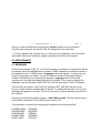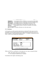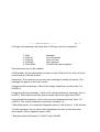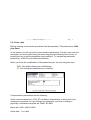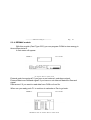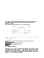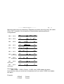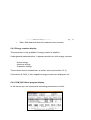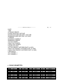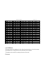
1
CVM_ST SOFTWARE 3.x
(Cod 7 75 042)
INSTRUCTION MANUAL
( S 42-2 / 95 )
(c)
CIRCUTOR S.A.
------------- Software CVM_ST -------------
INDEX
1. Introduction.
2. CVM_ST contents.
3. Characteristics
4. Installation.
5. Performance.
5.1 Beginning.
5.2 New devices installation.
5.3 Set Up menu.
5.3.1 CVM data.
5.3.2 Com data.
5.3.3 ER data.
5.3.4 ER/REDMAX Module.
5.3.5 ER/RedC2 Module.
5.3.6 ER/Red420 Module.
5.3.7 R8 Alarm program.
5.3.8 R8 PLC program.
5.3.9 R8 Power control program.
5.3.10 Memory.
5.4 Display mode.
5.4.1 General parameters.
5.4.2 Maximeter display.
5.4.3 Energy counters display.
5.4.4 R8 Alarm program display.
5.4.5 R8 PLC program display.
5.4.6 R8 Power control program display.
5.4.7 Memory program display. Data load and M.C.
6. Delete a CVM.
7. Network test.
Pag.
1
------------- Software CVM_ST -------------
Pag.
2
1.0 INTRODUCTION.
Welcome to CVM_ST, the basic software for CVM family users. This software runs
under MS-DOS 5.0 version or higher.
This program let you configure and display any CVM instrument, as well as the CVMR8 peripheral. It can support up to 12 instruments connected in a network. These
instruments are easily accessible from CVM_ST.
In the display option we will be able to see all CVM family parameters.
2.0 CVM_ST CONTENTS.
CVM_ST is supplied with following items:
þ 3.5" , 1.4 Mbyte diskette with CVM_ST program.
þ Instruction manual.
þ Register card.
3.0 CHARACTERISTICS.
CVM_ST allows the centralization of several CVM measurement points at one
computer.
All the readouts get from CVM are instantaneous, so the communications between
instruments and the computer are made in real time.
The parameters displayed by the computer can also be stored in the Hard Disk, to
export them to other programs as LOTUS, EXCEL,....
4.0 INSTALLATION.
Before installing the program, be sure that your system has the required equipment
for a proper operation.
The equipment must be the following: MS-DOS 5.0 (or higher) plus one serial
communication port (or more).
------------- Software CVM_ST -------------
Pag.
3
Once you have checked the environment, Install program can be executed.
Following the computer will install CVM_ST program in your hard disk.
+ Fill the register card and sent it to us. Once you are registered, you will receive
information about new products, updates programs and technical support.
5.0 PERFORMANCE.
5.1 BEGINNING
Execute the program CVM_ST. If it is the first time you execute it, a password will be
requested, being this password the number 775042 followed by the serial number of
the diskette (from 1 to 9999); after a language menu will appear , in which you can
select the language you desire. Use arrow keys to choose it and press Enter to
validate. Second time you execute the program, language choice will not be
required, as it will take by default the last you selected. If you want to change the
language, you should delete LING.DAT file, and execute again CVM_ST program.
The first time you enter in the CVM_ST program, NET_485.DAT file will not be
found, in which network configuration is stored. To advise that the file is not found a
message will appear on screen. The file will not exist until you add any instrument in
the network .
Following, the following options appear: Add CVM and Quit. The first option let you
add another instrument in the network (see section 5.2).
The possibility to choose the language will depend on the following files:
LINGESP.MSG
LINGGB.MSG
LINGFR.MSG
LINGDE.MSG
LINGIT.MSG
SPANISH
ENGLISH
FRENCH
GERMAN
ITALIAN
------------- Software CVM_ST -------------
Pag.
4
5.2 NEW INSTRUMENTS INSTALLATION
For a proper installation of new instruments, please follow the next steps:
1.- Physical disconnection of all instruments connected to the network.
2.- Connect only the instrument you want to install.
After that, go to Add option and write peripheral number, by default number 00
appears (CVM has 00 number by default, too). Using 00 you can communicate to
any CVM, although it has assigned another number, therefor, it is essential to have
disconnected the rest of CVMs.
Then press Enter to communicate to the instrument. If the action is successful*, it will
show the current transformer status, with the messages: Correct, Inverted or There is
not current.
* CVM_ST will automatically change serial port and baud rate if the communication
causes an error. It will try:
COM1: 9600, 4800, 2400
COM2: 9600, 4800, 2400
5.3 SET UP MENU.
The set up menu is automatically selected depending on the instrument you have
connected, CVM with or without ER module, CVM_R8C, ...
The following options are available:
CVM data General data of the CVM.
Com. data Communication parameters ( we suggest not to modify
these parameters)
ER module Energy and time module data.
ER/REDMAX It only appears when a CVM has connected this target (231).
------------- Software CVM_ST -------------
Pag.
5
ER/REDC2
It only appears when a CVM has connected this target (242).
ER/RED420 It only appears when a CVM has connected this target (251).
R8 program It only appears when a CVM_R8C is connected. This
option will be different depending on the CVM-R8C program you have.
Memory
It only appears when a CVM-M is connected. This option
includes set-up data.
Back to menu This option will return us to the main menu.
5.3.1 CVM data.
In this section you will set up the instrument you selected. Put the cursor over the
parameter you want modify using the arrow keys and write directly the new one, or
press Enter key to edit the parameter and modify it. To validate the parameter press
Enter, or ESC to quit without any modification.
When you finish the modification of the parameters, you can exit using two keys:
- ESC: Quit without saving the modifications.
- F1: Exit saving the parameters you modified.
Parameters of this option are following ones:
------------- Software CVM_ST -------------
Pag.
6
CVM type: this parameter will show which CVM type you have connected.
1. CVM
2. CVM-4C
3. CVM-DC
4. CVM-MD
5. CVM-R8-AL
Standard
Four Quadrants
Direct Current
Max. Demand
CVM-R8 with alarm program
This parameter can not be modified.
CVM Number: It is the identification number of each CVM (from 01 to 99). 00 is the
number that all CVM will answer.
Description: The customer can write his own message to identify the device. This
message will appear on the main screen.
Voltage transformer primary: Value of the voltage transformer primary (from 1 to
500000 V).
Voltage transformer secondary: Value of the voltage transformer secondary (from 1
to 999 V). Ratio between primary and secondary cannot be higher than 9090.
Current transformer primary: Value of the current transformer primary (from 1 to
10000 A). The current transformer secondary is always 5 A.
* Maximeter period: it is maximeter integration period, it will be from 1 to 60 minutes.
*Control parameter: let you select which parameter you want in the maximeter:
Active power (kW) or Apparent power (kVA).
* Both these data will appear in CVM-4C and CVM-MD
------------- Software CVM_ST -------------
Pag.
7
5.3.2 Com. data
Before entering in this section a password will be requested. This password is: 9999
plus Enter.
In this section you will set up the communication parameters. Put the cursor over the
parameter you want modify using the arrow keys and write directly the new one, or
press Enter key to edit the parameter and modified it. To validate the parameter
press Enter, or ESC to quit without modification.
When you finish the modification of the parameters you can exit using two keys:
- ESC: Quit without saving the modifications.
- F1: Exit saving the parameters you modified.
Communication parameters are the following:
Serial communication port: CVM_ST can detect automatically in which port is the
instrument connected, so if you change this parameter you have to change it
physically. Available serial ports are COM1 & COM2.
Baud rate: 2400, 4800 or 9600.
Serial data: 7 or 8 bits
------------- Software CVM_ST -------------
Pag.
8
Parity: Even , Odd or No (without parity control).
Stop bit: 1 or 2 bits.
NOTE: Do not modify communication parameters unless it is necessary.
5.3.3 ER data.
Before entering in this section a password will be requested. This password is: 9999
plus Enter.
In this section you will set up the energy and clock parameters. Put the cursor over
the parameter you want modify using the arrow keys and write directly the new one,
or press Enter key to edit the parameter and modified it. To validate the parameter
press Enter, or ESC to quit without any modification.
When you finish the modification of the parameters you can exit using two keys:
- ESC: Quit without saving the modifications.
- F1: Exit saving the parameters you modified.
This option only will appears if you have installed CVM/ER module.
------------- Software CVM_ST -------------
Pag.
9
Energy and clock parameters are the following:
DATE (DD/MM/YYYY): Date parameter. Its format is: day / month / year. The year
parameter can be four or two characters, if is two characters and the number is
under 80, for example 01, then CVM will store 2001.
TIME (HH:MM): you set the time. The format is: hour : minutes . 00<hour<23 and
00<min.<59.
Initial active energy value: This value is the initial active energy value you want to
begin to count from. Remember that this value will be fixed in the instrument when
you finish the configuration and if you exit using F1 key.
Initial inductive energy value: This value is the initial inductive energy value you want
to begin to count from. Remember that this value will be fixed in the instrument when
you finish the configuration and if you exit using F1 key.
Initial capacitive energy value: This value is the initial capacitive energy value you
want to begin to count from. Remember that this value will be fixed in the instrument
when you finish the configuration and if you exit using F1 key.
*Initial negative active energy value: This value is the initial negative active energy
value you want to begin to count from. Remember that this value will be fixed in the
instrument when you finish the configuration and if you exit using F1 key.
*Initial negative inductive energy value: This value is the initial negative inductive
energy value you want to begin to count from. Remember that this value will be fixed
in the instrument when you finish the configuration and if you exit using F1 key.
*Initial negative capacitive energy value: This value is the initial negative capacitive
energy value you want to begin to count from. Remember that this value will be fixed
in the instrument when you finish the configuration and if you exit using F1 key.
*only available on CVM-4C
------------- Software CVM_ST -------------
Pag.
10
5.3.4. REDMAX module.
With this module (Card Type 0231) you can program CVMk to store energy in
three differents tariff.
In first menu will appear:
External peak hours signal? If you have or not external peak hours signal.
External Maximum Demand signal? If you have or not external Maximum Demand
signal.
Data source? If you want to read data from CVMk or from file.
When are you ready push F1 to continue to calendar or Esc to go back.
------------- Software CVM_ST -------------
Pag.
11
In this screen you can program the differents types of days, with a maximum of 7.
You have 8 differents periods to program in one day. Its important to put a
description of the day.
With PagUp/PagDown change the day, with F1 go to next page:
Here you must program all the days of the year with the differents types of day. You
must push the day (0,,7) and move over the month with cursor key. To change moth
push PgUp/PgDown.
0-7 days: Pushing over the numbers 0 to 7 select the different type of day.
F1 Save CVMk & Disk: Send the programation to CVMk and store to a file.
F2 Save CVMk: Send the programation to CVMk.
F3 Save Disk: Store programation to a file.
ESC Exit: Goes out without saving anything.
5.3.5. CVM/RED-C2 Module
This module (Card Type 0242) provides
independently set as either an alarm or an
output as a pulse or alarm will depend on
selected, so, if the parameter is within 1 and
is within 32 and 38 the output will be a pulse.
two external outputs which can be
energy pulse. the performance of the
the electrical parameter that we have
30 the output will be an alarm, and if it
------------- Software CVM_ST -------------
Pag.
12
To change that parameter just place over it and press Enter. We can then choose
the variable with the é and ê keys and finally pressing Enter to validate the our
selection.
If an output is set as an alarm, four parameters are available:
• Variable: The variable measured by the CVM that we want to control, from 1
to 30.
• Minimum: Minimum value of the alarm condition. If the value measured by the
CVM is lower than this the output is activated.
• Maximum: Maximum value of the alarm condition. If the value measured by
the CVM is higher than this the output is activated.
• Delay: The period of time in seconds that the alarm condition must be
occurring to provoke the output activation.
If an output is set as an energy pulse, two parameters are available:
• Variable: The variable measured by the CVM that we want to control, from 32
to 38.
• Pulse: Value of the energy in W/h, varL/h or varC/h that must be reached to
generate a pulse output.
5.3.6. CVM/RED-420 Module
This module (Card Type 0251) has a 4-20 mA output linked to any variable
measured by the CVM.
Configuration parameters:
•
•
•
•
Parameter: Variable measured by the CVM, from 1 to 30.
Offset: Reference value taken as the zero (0/4 mA) for the output.
Full scale value: Value to which we assign the 20 mA.
Output mode: We can select among a 0-20 mA or a 4-20 mA output.
------------- Software CVM_ST -------------
Pag.
13
5.3.7 R8 alarm program.
This option allows programming:
- Up to 50 alarms with any parameter from the CVM.
- A/D channel parameters: offset & full scale values.
At the bottom of the screen you can see the following menu:
•
•
•
•
•
F5: Alarms
F6: Relays
F7 A/D channels
F1: Save
ESC: Exit
F5: Alarms
Following data appear on the screen:
Nº : It indicates the alarm number. It is not possible to modify it.
Parameter: It is the electric parameter to be controlled. Place the cursor over the
parameter you want to modify using the arrow keys to select it. Press Enter to
validate the parameter, or ESC to leave the previous one.
------------- Software CVM_ST -------------
Pag.
14
Maximum and minimum parameters: Depending on these values the relay will switch
ON or OFF. Herewith it is enclosed the following table explaining different
configurations:
MIN+ < MAX+
ON
0
MIN+ > MAX+
OFF
0
MIN -
MAX+
ON
MIN+
MAX -
OFF
MIN - < MAX -
ON
max
0
ON
OFF
min
max
0
OFF ON
max
min 0
MIN+
ON
MIN -
MAX
desactivate
MIN
MAX+
desactivate
MIN
MAX desactivate
max
OFF
min 0
MIN - > MAX MAX
desactivate
OFF
ON
min
max
ON
OFF
min
ON
max
OFF
min
ON
OFF
OFF
0
min
ON
OFF
min
0
OFF
ON
0 max
OFF
ON
max
0
Parameter range:
Max. or Min.: -9.999 < Param. < 9.999, and 10.000 disable the alarm.
Note that the value you enter has 4 characters and if you enter 10.000 is to disable
the alarm.
Example:
300 kW
1.23 kW
Correct
Correct
------------- Software CVM_ST -------------
555.32 kW
Pag.
15
Error: There are more than 4 characters
WARNING:
Voltage parameter has another set-up rules:
First of all it is necessary to explain that CVM_R8C works with "kV" units, but you
enter "V", therefore if CVM_R8C accept 4 characters of "kV" and you enter "V", the
range values are the following: -999.900< Volts < +999.900, and 1.000.000 is to
disable the alarm.
That means that if you enter 10.540 V, the value is accepted because for the
CVM_R8C that value is 10,54 kV and it has 4 digits, but if you enter 10.543 V,
CVM_R8C takes this value as 10,543 kV and it can not be accepted because it has 5
digits.
Delay: It is the time the relay takes to activate. The value range is between 0 and 99
sec.
Relay: This shows the relay number we want to activate, for CVM_R8C the possible
values are 1 to 8 and if you also have CVM_R10 the values are 1 to 18.
To finish, press ESC key.
F6 Relays:
This option let you validate or invalidate relay status, using arrow keys and pressing
enter over the relay you want to set.
To finish, press ESC key.
F7 A/D channels:
Offset and full scale programming of two analog channels.
Using arrow keys you can place the cursor over the A/D channel you want to set.
After that, you can directly enter the number, or pressing Enter you edit the number.
Values are between -20.000 to +20.000.
------------- Software CVM_ST -------------
Pag.
16
F1 Save:
This option sends all modifications you have done to the instrument and checks
them. If wrong parameters are transmitted, it will appear a message saying which
alarm can not be set.
ESC Exit:
This option does not transmit the information to the CVM_R8C and go back.
5.3.8 R8 PLC program.
PLC program provides us a complete set of instructions suitable for the generation of
multiple PLC performances.
Entering in this section following options are available:
· F5 : Diagram
· F6 : A/D channels
F5 Drawing
With this option we enter in the CIR_LD program, which will allow us designing a
logical circuit with the addition of relays, timers, meters, etc.
Due to the complexity of the program and the necessity of showing some examples,
it has been separately edited.
¡WARNING! : F4 Transfer option of CIR_LD program, needs a minmum quantity of
memory, if computer does not have enough memory, you should execute Memmaker
program from DOS, if still memory is not enough, transfer the automat program
through DOS executing CIR_SEND <progname.OBJ>.
------------- Software CVM_ST -------------
Pag.
17
F6 A/D channels and stop/start relays
The CVM-R8C peripheral has two A/D channels, where zero and full scale value can
be programmed. You place over the data to be modified with the cursor keys,
entering directly the value or with the Enter key which edits the data.
Values must be within -20.000 and 20.000.
Two relays which can be programmed as Normal or Stop/Start are also available.
With Enter key the relay type is changed.
F1 Save
This option send the modifications to the CVM-R8C equipment.
Following we pass to the previous menu.
ESC Exit
With this option we exit the set-up option without any modification.
5.3.9 R8 Power control program.
Power control program allows the regulation of the power at any installation, keeping
the power consumption below a certain value. In case that the trend is to exceed the
prefixed limit, the P.L.C. will order the disconnection of loads as per the previously
set up priority. The program works with sliding window system.
Entering in this section following set up parameters are available:
· Parameter to be controlled (Active P. or Apparent P.).
· Maximeter power.
· Integration period.
------------- Software CVM_ST -------------
Pag.
18
· Hysteresis margin.
· Disconnection priority of the relays.
Parameter to be controlled
This parameters refers to the power type we want to control. Pressing Enter when we
are over this option a menu with two options (Active power or Apparent power) is
shown up.
Maximeter power
Upper limit in Watts for the power consumption.
Integration period
Period in minutes of the maximeter, which can be within 1 and 60 minutes. It should
be the same as for the electrical utility and, if it is possible, for the CVM.
Hysteresis margin
It is a zone under the prefixed power where no operation is carried out. It can be
programmed from a 0 to a 100 % of the prefixed power. This value will depend on
the load size, as the lower the loads are the lower the hysteresis margin must be.
Disconnection priority of the relays
This data is the disconnection priority chart, from the highest to the lowest. The
output relays (between 2 and 8, and between 2 and 18 if R10 peripheral is also
connected) will be shown. The 1 output has been fixed as an error alarm (if the
communication with the CVM is lost). Relays will be entered with a comma
separation and from lower to higher disconnection priority.
F1 Save
This option send the modifications to the CVM-R8C equipment. It only allows
modification provided all relays are open.
------------- Software CVM_ST -------------
Pag.
19
Following we pass to the previous menu.
ESC Exit
With this option we exit the set-up option without any modification.
5.3.10 Memory.
Put the cursor over the command you want to work with and press the Enter key to
spread down the available options. Then using the arrow keys select the desired
option.
F WARNING: Each option of this screen is explained in the own user’s manual of
the device (CVM-M).
If we work with the special file type, a new screen containing 180 configurable
parameters will appear. This is the storage record of the parameters we want to
save.
<Ins>
Key allowing to insert a new parameter from the cursor position.
<Del>
Key to eliminate the parameter placed at the cursor position.
<Space> The space bar activates all the previous parameters from the present
cursor position, only the active ones will be saved.
<CR>
The Enter key followed by the é or ê arrows allows to select a
parameter. A description of this parameter is shown in the lower side.
F1 Save
This option sends the done modification to the CVM-M and check that they are
correct.
ESC Exit
This option do not provoke any change in the device. It can be used, for instance, if
we are not sure of the changes we have done.
------------- Software CVM_ST -------------
Pag.
20
5.4 DISPLAY MODE.
5.4.1 General parameters.
This option displays instantaneous data from the instruments connected to the
computer.
Each instrument has different parameters to show, so it will be different screens of
presentation.
While you are getting the information from an instrument, you can store it in the
computer.
< ENTER key: It stores the energy counters (if it has energy module) in a file called:
Dddmmyy.WAT, where:
dd = day number
mm = month number
yy = year number
So each day it will change the file automatically.
< F1 key: It stores the displayed electrical parameters.
F Files has a format which can be easily exported to other programs.
Displayed parameters are (except CVM_DC and CVM_R8C) :
------------- Software CVM_ST -------------
Pag.
21
• Voltage: by default it shows voltage between phases (ph/ph), if you press space it
will display phase-neutral voltage (ph/n). Voltages are show in V units, but if the
value exceed of 9999 V the scale is automatically changed to kV.
• Current: this parameter is displayed in A units, but if its value is bigger than 999 A,
then the units will change to kA .
• Active power: this parameter is displayed in Watt units, but if its value is bigger
than 9999 W then the units will change to kW .
• Inductive power: this parameter is displayed in VarL units, but if its value is bigger
than 9999 VarL then the units will change to kVarL .
• Capacitive power: this parameter is displayed in VarC units, but if its value is
bigger than 9999 VarC then the units will change to kVarC .
• Power Factor: The cosϕ of each phase and of the three phases together is
displayed
• Frequency: The frequency is displayed in Hz units.
5.4.2 Maximeter Display
This parameter is only available in CVM_MD and CVM_4.
Following data will appear:
•
Period: It is the integration period we have programmed, in minutes.
•
Max. last reset: It is the maximum since last reset. This maximum is in
kW or kVA depending on the parameter you had selected.
•
Max. last period: This is the maximum of the last period of integration.
Because it uses a sliding window this parameter will be refreshed every
second.
------------- Software CVM_ST ------------•
Pag.
22
Date: Date and time when the maximum has occurred.
5.4.3 Energy counters display.
This parameter is only available if energy module is installed.
Under general parameters box, it appears another box with energy counters.
- Active energy.
- Inductive energy.
- Capacitive energy.
These values can be initiated from a certain value (see section 5.3.3.)
If the device is CVM_4, then negative energy counters are displayed, too.
5.4.4 CVM_R8C Alarm program display.
In this screen you can see several interesting parameters to check.
------------- Software CVM_ST -------------
Pag.
23
Alarm state: You can see the instantaneous status of each relay (closed or open)
and its parameters: alarm nº , variable, max., min., delay and relay number. It is
possible to see 5 alarms at the same time, to see the rest you have to press
PgUp/PgDn keys.
Relay validation: you can also see if the relays are or not validated.
A/D channels: A/D channels values appear at the bottom.
5.4.5 CVM_R8C PLC program display.
The display system of this peripheral involves some parameters which are really
useful for a proper use of it.
The data display of this peripheral is carried out in real time and the access to any
data is immediate.
SET_R8 offers the possibility of creating our own data display screens, including a
data description and an asociated memory position.
When entering this option, a screen name is requested, the default one is standard.
To create a new one, write the new name ( without extention as SET_R8
automatically gives the .AUT) and press Enter. 40 empty cells with the text "NOT IN
USE", where we can enter our data, will appear up. Its sintax is as follows:
<text> : R : < mem. nº > For relays
<text> : L : < mem. nº > For Long registers
To clear a full cell, enter a blank space in it and press Enter.
During the modification process a help key (Av Pag) shows a memory map of the
peripheral.
5.4.6 CVM_R8C Power control program display.
------------- Software CVM_ST -------------
Pag.
24
The display system allows to check the proper performance of the equipment.
The data display of this peripheral is carried out in real time and the access to any
data is immediate.
SET_R8 offers the possibility of creating our own data display screens, including a
data description and an associated memory position.
When entering this option, we have a default screen named power.aut. We can
modify the data pressing F5. Sintax is as follows:
<text> : R : < mem. nº > For relays
<text> : L : < mem. nº > For Long registers
To clear a full cell, enter a blank space in it and press Enter.
During the modification process a help key (Av Pag) shows a memory map of the
peripheral.
5.4.7 Memory Display. Data load and M.C.
Data display option
Display of any file of the CVM-M. In case of a *.CVT file (special), we will see on
screen the parameters that have not been selected with a zero value. In case of a
*.CVM (standard) only the following parameters are saved:
*.CVM File
------------- Software CVM_ST -------------
Pag.
25
DATE
TIME
STORING PERIOD
PHASE-NEUTRAL VOLTAGE
MAXIMUM PHASE-NEUTRAL VOLTAGE
MINIMUM PHASE-NEUTRAL VOLTAGE
CURRENT
MAXIMUM CURRENT
MINIMUM CURRENT
ACTIVE POWER
INDUCTIVE POWER
CAPACITIVE POWER
POWER FACTOR
ACTIVE ENERGY (INTEGER PART & /1000)
INDUCTIVE ENERGY (INTEGER PART & /1000)
CAPACITIVE ENERGY (INTEGER PART & /1000)
FREQUENCY
AD CHANNEL 1
AD CHANNEL 2
F CVM-M PARAMETERS:
Nº
0
1
2
3
4
5
6
7
8
9
10
VARIABLE
V1
A1
kW1
kvar L1
kvar C1
PF 1
V2
A2
kW2
kvar L2
kvar C2
Nº
46
47
48
49
50
51
52
53
54
55
56
VARIABLE
kW3mx
kvar L3mx
kvar C3mx
PF3mx
Vav III Nmx
Aav IIImx
kWIIImx
kvar LIIImx
kvar CIIImx
PF IIImx
Hzmx
Nº
90
91
92
93
94
95
96
97
98
99
100
VARIABLE
V12mn
V23mn
V31mn
Vav IIImn
DC1mn
DC2mn
nkW1
nkvar L1
nkvar C1
nkW2
nkvar L2
Nº
136
137
138
139
140
141
142
143
144
145
146
VARIABLE
kvarCh-1
kvarCh/1000-1
nkwh-1
nkwh/1000-1
nkvarLh-1
nkvarLh/1000-1
nkvarCh-1
nkvarCh/1000-1
kwh-2
kwh/1000-2
kvarLh-2
------------- Software CVM_ST ------------11
12
13
14
15
16
17
18
19
20
21
22
23
24
25
26
27
28
29
30
31
32
33
34
35
36
37
38
39
40
41
42
43
44
45
PF2
V3
A3
kW3
kvar L3
kvar C3
PF3
Vav III N
Aav III
kWIII
kvar LIII
kvar CIII
PF III
Hz
kVA III
V12
V23
V31
Vav III
DC1
DC2
V1mx
A1mx
kW1mx
kvar L1mx
kvar C1mx
PF 1mx
V2mx
A2mx
kW2mx
kvar L2mx
kvar C2mx
PF2mx
V3mx
A3mx
57
58
59
60
61
62
63
64
65
66
67
68
69
70
71
72
73
74
75
76
77
78
79
80
81
82
83
84
85
84
85
86
87
88
89
kVA IIImx
V12mx
V23mx
V31mx
Vav IIImx
DC1mx
DC2mx
V1mn
A1mn
kW1mn
kvar L1mn
kvar C1mn
PF 1mn
V2mn
A2mn
kW2mn
kvar L2mn
kvar C2mn
PF2mn
V3mn
A3mn
kW3mn
kvar L3mn
kvar C3mn
PF3mn
Vav III Nmn
Aav IIImn
kWIIImn
kvar LIIImn
kWIIImn
kvar LIIImn
kvar CIIImn
PF IIImn
Hzmn
kVA IIImn
101
102
103
104
105
106
107
108
109
110
111
112
113
114
115
116
117
118
119
120
121
122
123
124
125
126
127
128
129
130
131
132
133
134
135
nkvar C2
nkW3
nkvar L3
nkvar C3
nkWIII
nkvar LIII
nkvar CIII
nkW1mx
nkvar L1mx
nkvar C1mx
nkW2mx
nkvar L2mx
nkvar C2mx
nkW3mx
nkvar L3mx
nkvar C3mx
nkWIIImx
nkvar LIIImx
nkvar CIIImx
nkW1mn
nkvar L1mn
nkvar C1mn
nkW2mn
nkvar L2mn
nkvar C2mn
nkW3mn
nkvar L3mn
nkvar C3mn
nkWIIImn
nkvar LIIImn
nkvar CIIImn
kwh-1
kwh/1000-1
kvarLh-1
kvarLh/1000-1
Pag.
147
148
149
150
151
152
153
154
155
156
157
158
159
160
161
162
163
164
165
166
167
168
169
170
171
172
173
174
175
176
177
178
179
26
kvarLh/1000-2
kvarCh-2
kvarCh/1000-2
nkwh-2
nkwh/1000-2
nkvarLh-2
nkvarLh/1000-2
nkvarCh-2
nkvarCh/1000-2
kwh-3
kwh/1000-3
kvarLh-3
kvarLh/1000-3
kvarCh-3
kvarCh/1000-3
nkwh-3
nkwh/1000-3
nkvarLh-3
nkvarLh/1000-3
nkvarCh-3
nkvarCh/1000-3
nPF 1
nPF 2
nPF 3
nPF III
nPF 1 mx
nPF 2 mx
nPF 3 mx
nPF III mx
nPF 1 mn
nPF 2 mn
nPF 3 mn
nPF III mn
Load CVM-M data
This option allows the reading of a file, either from the device or from the memory
card inserted into it, saving the file in the hard disk of the computer.
This option is also useful for creating a directory of the card.
File export
------------- Software CVM_ST -------------
Pag.
27
Creates a file in ASCII format exportable to a standard dataspread software. The
name of the file is the same and the extension will be txm, txt, txp, txx or txe,
depending on the original file.
Functions of the memory card
Rename a file: select the file and rename it.
Delete a file in the card: select the file to be deleted.
Format the card.
6 DELETE A CVM.
This option let you delete a CVM from the network. Once you have deleted it, its
name disappears from the screen.
7 NETWORK TEST
Use this option to verify all the instruments connected to the computer. If the
instrument can communicate with the computer then OK ! message appears beside
it, but if the communication is failed then Err message appears beside it.