1
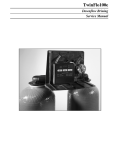
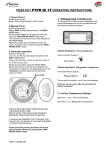
6600 - 6665 AND
6665 DVGW VALVES
6600
6665
SERVICE MANUAL
1
VALVE SPECIFICATION
P. 2
2
VALVE INSTALLATION
P. 3
3
INSTALLATION INSTRUCTIONS
P. 4
4
VALVE OPERATION
P. 5
5
TROUBLE SHOOTING
P. 9
1 - VALVE SPECIFICATION
Installation N°
System capacity
m3°TH
Valve serial N°
Inlet water hardness
°TH
Tank size
Water hardness after mixing valve
°TH
Resin type
Brine tank size
L
Resin volume
Quantity of salt per regeneration
Kg
VALVE TECHNICAL CHARACTERISTIC
INITIATION
REGENERATION SET AT
Time clock
Days
Meter delayed
REGENERATION TIME
Meter immediate
2 o’clock A.M.
/
or
m3 or l
Hour
REGENERATION CYCLES SETTING
Cycle 1
min
Cycle 2
min
Cycle 3
min
Cycle 4
min
Cycle 5 (only 6665 DVGW)
min
Cycle 6 (only 6665 DVGW)
min
Pressure Regulator
HYDRAULIC SETTING
2,1 bar (30 PSI)
1,4 bar (20 PSI)
Injector size
Without
Drain line flow control (DLFC)
GPM
Brine line flow control (BLFC)
GPM
VOLTAGE
24V / 50Hz
24V / 60Hz without transformer
NOTES
2
VALVE 6600-6665-6665 DVGW
2 - VALVE INSTALLATION
2.1
WATER PRESSURE
A minimum of 1,4 bar of water pressure is required for regeneration valve to operate effectively. Do not exceed 8,5
bar ; if you face this case, you should install a pressure regulator upstream the system.
2.2
ELECTRICAL CONNECTION
An uninterrupted alternating current supply is required. Please make sure your voltage supply is compatible with
your unit before installation. If the electrical cable is damaged, it must imperatively be replaced by a qualified
personal.
2.3
EXISTING PLUMBING
Existing plumbing should be in a good shape and free from lime. The installation of a pre-filter is always advised.
2.4
BY-PASS
Always provide a by-pass valve for the installation, if unit is not equipped with one.
2.5
WATER TEMPERATURE
Water temperature is not to exceed 43° C, and the unit cannot be subjected to freezing conditions.
2.6
PRESENTATION
Service Indicator
Time of day display indicator
Reserve indicator :
Valve in service : arrow on
Regeneration tonight : flashing arrow
time of day display: arrow on
Volume remaining at or below the reserve :
flashing arrow
R
Flow indicator :
Arrow flashes with water flow
R
Regeneration indicator :
Volume remaining display indicator :
Program display indicator :
Arrow on
Arrow on
Arrow on
Up and Down set button
Program button
1
4
2
Extra cycle button
3
3
VALVE 6600-6665-6665 DVGW
3 - INSTALLATION INSTRUCTIONS
3.1
Install the unit making sure the tank is level and on a firm base.
3.2
During cold weather it is recommended that the installer warms the valve up to the room temperature before operating.
3.3
All plumbing should be done in accordance with local plumbing code. The pipe size for the drain line should be a
minimum of 13 mm (1/2’’). For length in excess of 6 m, the drain line should be a minimum of 19 mm (3/4’’).
3.4
Solder joints on the principal plumbing and near the drain must be done prior to connecting the valve. Failure to do
this could cause irreversible damage to the valve.
3.5
Teflon® tape is the only sealant to be used on the drain fitting.
3.6
Make sure that the floor is clean beneath the salt storage tank and that it is level.
3.7
On units with a by-pass, place in by-pass position. Turn on the main water supply. Open a cold soft water tap
nearby and let run a few minutes or until the system is free from foreign material (usually solder) that may have
resulted from the installation. Once clean, close the water tape.
3.8
Place the by-pass in service position and let water flow into the mineral tank. When water flow stops, slowly open
a cold water tap nearby and let run until the air is purged from the unit.
3.9
Plug the valve into an approved power source. Once powered, it is possible that the valve drives itself to the
service position.
3.10
Set the time of day (see chap.4.1.2).
3.11
Fill approximately 25 mm of water above the grid plate, (if used). Otherwise, fill to the top of the air check in the brine
tank. Do not add salt to the brine tank at this time.
3.12
Initiate a manual regeneration (see chap.4.2.2). Let flow the water during 3 or 4 minutes. Bring the valve into each
regeneration cycle and check the functioning of each step. Bring the valve in brine draw position (see chap. 4.2.3)
and let it draw the water contents in the brine tank until it stops. The water level will approximately be in the middle of the air check cage.
3.13
Now bring the valve in brine refill position (see chap.4.2.3) and let it get back to service position automatically.
3.14
Now you can add salt to the brine tank, the valve will operate automatically.
3.15
It is recommended to install a 9V alkaline battery at all times for proper valve operation.
4
VALVE 6600-6665-6665 DVGW
4 - VALVE OPERATION
Timeclock regeneration valves
The valve will operate normally until the number of days since last regeneration reaches the regeneration day
override setting. Once this occurs, a regeneration cycle will be initiated at the pre-set regeneration time.
Immediate or meter delayed regeneration valves
The volume remaining display will count down from a maximum value to zero. Once this occurs, a regeneration will
be initiated immediately or delayed to the set regeneration time.
For example :
R
R
R
R
845 litresof treated water remaining
0 litre of treated water remaining
Immediate or meter delayed regeneration with days override set
When the valve reaches its set of days since regeneration override value, a regeneration will be initiated
immediately or at the preset regeneration time. This event occurs regardless of the volume remaining display.
Special mode DVGW (German norm)
This valve is in immediate and upflow regeneration, with chlorination and “pause-vacancy” position.
The particularity of the “pause-vacancy” position :
• When there is not a flow rate detected for 4 days running :
- the valve initiates a regeneration and returns in service
• When there is not still a flow rate detected for next 4 days running :
- the valve initiates a regeneration and stops at the “pause-vacancy” position
- the valve will end the regeneration and return in service only when there will be a flow rate detected.
Variable brining mode (only for meter delayed up flow)
The valve will determine that a regeneration is required when the volume remaining drops to the reserve
capacity. The regeneration will begin immediately at the set regeneration time. The volume of the brine depends on
the volume of the softened water consummate, therefore the time of the brine refill is calculated by the electronic.
5
VALVE 6600-6665-6665 DVGW
4 - VALVE OPERATION
4.1
SERVICE
4.1.1
SERVICE DISPLAYS
In service operation, the time of day and the volume remaining will alternatively be viewed, (except for the timeclock version : only the time of day will be viewed)
R
R
R
Time of day
4.1.2
R
R
R
Volume remaining : 845 l
Volume remaining : 0 l.
TIME OF DAY SETTING
Set minute by minute the time of day display by depressing the
Depress and hold the
or
or
button.
button to set quickly the time of day.
4.2
REGENERATION
4.2.1
REGENERATION DISPLAYS
In regeneration operation, the valve will show the current regeneration cycle number the valve is advancing to (flashing display) or has reached and the time remaining in that step (fixed display). Once all regeneration cycle steps
have been completed the valve will return to the service position.
For example :
R
R
R
R
For valves with chlorinator,
the letter C indicates its functioning
Regeneration step #1 has been reached
9,3 minutes remain in step #1
4.2.2
SART A MANUAL REGENERATION
There are two options to initiate a regeneration :
1
2
1) - Press and release the button
• With an immediate regeneration, the valve will start immediately a regeneration.
• With a delayed regeneration, the service arrow will begin to flash immediately and the regeneration will occur
at the preset regeneration.
4
3
1
2
2) - Press and hold for 5 seconds the button
• In any case, the valve will go into regeneration immediately.
4
6
3
VALVE 6600-6665-6665 DVGW
4 - VALVE OPERATION
4.2.3
ADVANCE TO THE NEXT REGENERATION CYCLE
1
To advance to the next regeneration cycle position, push the button
valve is advancing to the next cycle.
4.3
4
2
3
. This action won’t have any effect if the
PROGRAMMING
CAUTION : the programming has to be only done by the installer for the valve setting of parameters.
The modification of one of these parameters could prevent the good functioning of the device.
To enter the program mode the valve has to be in service. While in the program mode, the valve will continue to
operate normally monitoring all information. The programming is stored in permanent memory with or without line
or battery backup power.
To enter in program mode, push and hold the button
Push the button
for 5 seconds
once per display.
Change the option setting by pushing either the button
or
.
Note: you must pass through all the programming step and come back in service position to save the
modifications that have been done during the programming mode.
R
Water hardness (not viewed in timeclock version)
For ex. : 30° tH
R
R
Water hardness after mixing valve (not viewed in timeclock version)
For ex. : 6° tH
R
R
Regeneration time (not viewed in immediate version)
For ex. : 2 o’clock AM
R
7
VALVE 6600-6665-6665 DVGW
4 - VALVE OPERATION
4.4
VALVE OPERATION DURING A POWER FAILURE
During a power failure all control displays will be turned off and regeneration cycles delayed. The valve will
otherwise continue to operate normally until the line power is restored or the battery backup power is lost.
If the battery backup power is never lost during a power outage, the valve will continue to operate normally,
recording all data until the lie power is restored.
If the battery backup power is lost during a power outage, the valve will store the current time of day, volume
remaining, regeneration cycle status and diagnostic displays. These stored displays will then be used upon the line
power restoration until updated ones are created. To indicate this type of failure, the time of day will flash showing
that this display and the volume remaining may not be correct.
8
VALVE 6600-6665-6665 DVGW
5 - TROUBLE SHOOTING
PROBLEM
1. Softener fails to
regenerate.
2. Softener delivers hard
water.
3. Unit uses too much salt.
CAUSE
CORRECTION
A - Electrical service to unit has been
interrupted.
A - Assure permanent electrical service
(check fuse, pull chain or switch).
B - Timer is not operating properly.
B - Replace the timer.
C - Meter cable disconnected.
C - Check the meter connection to the timer
and the meter cover.
D - Meter jammed.
D - Clean or replace the meter.
E - Defective valve drive motor.
E - Replace the drive motor.
F - Improper programming.
F - Check the programming and reset as
needed.
A - By-pass is opened.
A - Close the by-pass valve.
B - No salt in the brine tank.
B - Add salt to the brine tank and maintain
the salt level above the water level.
C - Injector and/or screen is plugged.
C - Replace or clean the injector and screen.
D - Insufficient water flowing into the brine
tank.
D - Check the brine tank fill time and clean
the brine line flow control if it’s plugged
(BLFC).
E - Hardness from the hot water tank.
E - Repeated flushing of the hot water tank
is required.
F - Leak at the distributor tube.
F - Make sure distributor tube is not
cracked. Check the O’ ring.
G - Internal valve leak.
G - Replace seals and spacers and/or
piston.
H - Flow meter is jammed.
H - Remove the obstruction from meter.
I - Flow meter cable is disconnected or not
plugged into the meter cap.
I - Check the meter connection to the timer
and the meter cap.
J - Improper programming.
J - Check the programming and reset as
needed.
A - Improper brine refill setting.
A - Check salt usage and salt setting.
B - Excessive water in the brine tank.
B - See the problem n° 7.
C - Improper programming.
C - Check the programming and reset as
needed.
9
VALVE 6600-6665-6665 DVGW
5 - TROUBLE SHOOTING
PROBLEM
4. Loss of water pressure.
5. Loss of resin through
drain line.
6. Iron in softened water.
7. Excessive water in
brine tank.
8. Salted water in service
line.
10
CAUSE
CORRECTION
A - Iron build up in line to softener.
A - Clean the line to the softener.
B - Iron build up in the softener.
B - Clean the valve and the resin bed.
C - Inlet of the valve plugged due to foreign
material.
C - Remove the piston and clean the valve.
A - Top distributor missing or broken.
A - Add or replace the top distributor.
B - Air in water system.
B - Assure the presence of air check system in the brine tank.
C - Drain line flow control is too large (DLFC).
C - Ensure drain line flow control size is
correct.
A - Fouled resin bed.
A - Check backwash, brine draw and brine
tank refill; increase frequency of regeneration; increase backwash time.
B - Iron exceeds the recommended
parameters.
B - Contact the dealer.
A - Plugged drain line flow control.
A - Clean drain line flow control (DLFC).
B - Brine valve failure.
B - Replace brine valve.
C - Improper programming.
C - Check programming and reset as
needed.
A - Plugged injector and/or screen.
A - Clean injector and replace screen.
B - Timer not operating properly.
B - Replace timer.
C - Foreign material in brine valve.
C - Clean or replace brine valve.
D - Foreign material in brine line flow control
(BLFC).
D - Clean brine line flow control.
E - Low water pressure.
E - Raise water pressure to 1,4 bar at least.
F - Improper programming.
F - Check programming and reset as
needed.
VALVE 6600-6665-6665 DVGW
5 - TROUBLE SHOOTING
PROBLEM
9 . Softener fails to draw
brine.
CAUSE
CORRECTION
A - Plugged drain line flow control.
A - Clean flow control (DLFC).
B - Plugged injector and/or screen.
B - Clean injector and/or replace screen.
C - Low water pressure.
C - Increase water pressure to 1,4 bar at
least.
D - Internal valve leak.
D - Change seals and spacers and/or piston
assembly.
E - Improper programming.
E - Check programming and reset as needed.
F - Timer not operating properly.
F - Replace timer.
10. The valve regenerates
continuously.
A - Timer not operating properly.
A - Replace timer.
B - Faulty microswitches and or harness.
B - Replace faulty microswitches and/or
harness.
C - Faulty cycle cam operation.
C - Replace cycle cam or reinstall.
11. Drain flows continuously.
A - Foreign material in the valve.
A - Remove piston assembly and inspect bore,
remove foreign material and check the
valve in various regeneration positions.
B - Internal valve leak.
B - Replace seals spacers and or piston
assembly.
C - Valve jammed in brine or backwash
position.
C - Replace piston assembly and seals and
spacers.
D - Timer motor stopped or jammed.
D - Replace timer motor and check all gears
for missing teeth.
E - Timer not operating properly.
E - Replace timer.
11
VALVE 6600-6665-6665 DVGW
MASTER PROGRAMMING MODE
Note :
1. Push the
per display.
P
The valve is in service position. To enter in the first level, push
and hold the
button for 5 seconds.
P
1.1. Water Hardness in °tH
Not viewed in timeclock regeneration mode
Ex.: 30 °tH
[H - - - -30]
1.2. Water Hardness after mixing valve in °tH
Not viewed in timeclock regeneration mode
Ex.: 6 °tH
[P - - - -6]
1.3. Regeneration time
Not viewed in immediate regeneration mode
Ex. : 02:00
[- - 2:00 -]
button once
2. Option settings may be changed by pushing the
and
set buttons.
3. Depending on current valve
programming, some displays will not be viewed or
set.
P
P
P
A
Level #1 exit.
The valve returns in normal operation.
VALVE 6600-6665-6665 DVGW
MASTER PROGRAMMING MODE
P
Note :
1. Push the
per display.
button once
2. Option settings may be changed by pushing the
and
set buttons.
3. Depending on current valve
programming, some displays will not be viewed or
set.
1
4
2
3
P
P
P
P
P
P
P
P
P
P
P
P
The valve is in service position. To enter in the second level,
push and hold the
button for 5 seconds.
Then depress the button
second level.
1
4
2
for 5 seconds.You are in the
3
2.1. Flow rate (Fr) in l/min (1)
Ex. : 8,6 l/mn
not adjustable
[Fr - - 8.6]
2.2. Days since the last regeneration (d)
Ex. : 2 days
not adjustable
[d - - - - 2]
2.3. Prior service volume used in litre
Ex. : 3483 l
not adjustable
[E - -3483]
2.4. Reserve capacity (rc) in litre (1) (2)
Ex. : 852 l
not adjustable
[rc - - 852]
2.5. Previous days water usage (Pd) in litre (1)
Ex. : 284 l
not adjustable
[Pd - -28.4]
2.6. System capacity in m3 °tH (c)
Ex. : 100 m3 °tH
[C- - - 100]
2.7. Cycle #1 :
Ex. : 6 minutes
[1 - - - 6.0]
2.8. Cycle #2 :
Ex. : 60 minutes
[2 - - 60.0]
2.9. Cycle #3 :
Ex. : 10 minutes
[3 - - 10.0]
2.10. Cycle #4 :
Ex. : 12 minutes
[4 - - 12.0]
2.11. Cycle #5
[5 - -OFF]
Only for DVGW mode
2.12. Cycle #6
[6 - -OFF]
Only for DVGW mode
Note : not viewed if cycle #5 is set on OFF.
P
2.13. Indicator of chlorination (J)
Ex. : - Chlorination during the cycle 1
- No chlorination
[J - - - - -1]
[J- - -OFF]
P
2.14. Regeneration day override (A)
Ex. : - Override every 7 days
- Cancel setting
[A - - - - 7]
[A - -OFF]
Note: in timeclock regeneration, never cancel this setting.
(1) not viewed in timeclock regeneration mode.
(2) not viewed in immediate regeneration mode.
(3) not viewed in case of override.
P
P
2.15. Volume override (b) in litre (1)
Ex. : - Regenerate every 2000 l
[b- - 2000]
Level #2 exit.
The valve returns in normal operation..
B
VALVE 6600-6665-6665 DVGW
MASTER PROGRAMMING MODE
Note :
1. Push the
per display.
P
button once
2. Option settings may be changed by pushing the
and
set buttons.
3. Depending on current valve
programming, some displays will not be viewed or
set.
1
2
4
3
1
2
4
3
P
The valve is in service position. To enter in the second level,
push and hold the
button for 5 seconds.
Then depress the button
second level.
1
4
2
3
After that, depress the button
third level.
for 5 seconds.You are in the
1
4
2
3
for 5 seconds.You are in the
3.1. Display format (U)
Ex.: - Litre format
- Cubic meter format
[U - - - - - 2]
[U - - - - - 4]
Note : If this parameter is changed, the programming comes
immediately back to the level 1 and is directly followed by the
levels 2 & 3.
P
P
P
P
P
P
P
C
3.2. Valve Type (o)
Ex.: - Valve 6600/6665/6665 DVGW
[o - - - - - 1]
3.3. Regeneration type (7)
Ex.: - Timeclock
- Meter immediate
- Meter delayed
- DVGW Mode
[7
[7
[7
[7
3.4. Flow meter size (F)
Ex.: - Standard 3/8”
- Standard 3/4”
[F - - - - - 0]
[F - - - - - 1]
3.5. Mixing valve location (8)
Ex.: - No mixing valve
- Mixing valve before flow meter
- Mixing valve after flow meter
[8 - - - - - 1]
[8 - - - - - 2]
[8 - - - - - 3]
3.6. System type (9)
Ex.: - System type #4 : single electronic
[9 - - - - - 4]
3.7. Program lockout(Pl)
Ex.: - Cancel lockout
- Lockout active
[Pl - - - OFF]
[Pl - - - - ON]
-
-
-
Level #3 exit.
The valve returns in normal operation
VALVE 6600-6665-6665 DVGW
-
-
1]
2]
3]
7]
MASTER PROGRAMMING MODE
Settings and displays can be viewed
or reset with active lockout
In service :
- Time of day
- Volume remaining
In programming level 1
- Water hardness
- Water hardness after mixing valve (P)
- Regeneration time
In programming level 2
- Flow rate (Fr)
- Days since the last regeneration (d)
- Prior service volume used (E)
- Reserve capacity (rc)
- Previous days water usage (Pd)
No possibility to enter in the level #3 if lockout is activated
The program lockout can be cancelled by depressing the button
for 25 seconds.
CAUTION : depressing the button
for 25 seconds when the program lockout is not activated will erase all previous display settings; the electronic will reset to default values. The electronic programming will have to be completely redone.
Installer note :
1. Reserve capacity calculation : in meter delayed regeneration mode, the electronic automatically calculates its reserve capacity based on daily water usage.
2. System capacity and water hardness will not be viewed or set when timeclock regeneration
is programmed ; when volume override is set, the system capacity will not be viewed.
3. The regeneration time will not be viewed or set with the metered immediate regeneration
mode.
4. Voltage range for reliable operation of the electronic:
Voltage : 24V +/- 10%
Frequency: 50Hz or 60Hz without transformer.
D
VALVE 6600-6665-6665 DVGW
Reproduction interdite 05/01 - P/N 27223
GB
Programming level 1
Note :
1. Push the
display.
The valve is in service position. To enter in the first level, push
and hold the button
for 5 seconds.
P
1.1. Water Hardness in °tH
Ex.: 30 °tH
[H - - - -25]
P
1.2. Water Hardness after mixing valve in °tH
Ex.: 6 °tH
[P - - - -6]
P
1.3. Regeneration time
Ex. : 02:00 A.M.
[- - 2:00 -]
P
Level #1 exit.
The valve returns in normal operation.
button once per
2. Option settings may be changed by pushing the
and
set buttons.
3. Depending on current valve
programming, some displays
will not be viewed or set.
A
P
Valve 6600 1600 UF VB
Programming level 2
Note :
P
1. Push the
display.
button once per
2. Option settings may be changed by pushing the
and
set buttons.
3. Depending on current valve
programming, some displays
will not be viewed or set.
The valve is in service position. To enter in the second level,
push and hold the button
for 5 seconds.
Then depress the button
5 seconds.
You are in the second level.
P
P
P
P
2.1. Flow rate in l/min
[Fr - - - 0]
not adjustable
2.2. Days since the last regeneration
[d - - - - 0]
not adjustable
2.3. Prior service volume used in litre
[E - -2800]
not adjustable
2.4. Reserve capacity in litre
[rc - - 450]
not adjustable
2.5. Previous day water usage in litre
P
not adjustable
[Pd - - 400]
P
2.6. System capacity in m3 °tH
Ex. : 30 m3 °tH
[C - - -30]
Cycle time settings :
P
P
P
P
P
P
P
P
P
2.7. Pause cycle to prepare the brine
Ex. : 30 min.
[2 - - 30.0]
2.8. Brine draw & slow rinse
Ex. : 50 min.
[3 - - - 50.0]
2.9. Backwash
Ex. : 8 min.
[4 - - - - 8.0]
2.10. Rapid rinse
Ex. : 10 min.
[5 - - - 10.0]
2.11. Not used
[6 - - - OFF]
2.12. Indicator of chlorinating
- no chlorinating indicator
[J - - -OFF]
2.13. Regeneration day override
Ex. : - override every 7 days
- cancel setting
[A - -OFF]
2.14. Volume override in litre
Ex. : - setting not used
[b - - OFF]
Level #2 exit.
The valve returns in normal operation.
B
Valve 6600 1600 UF VB
Programming level 3
Note :
1. Push the
display.
P
button once per
Then depress the button
5 seconds.
You are in the second level.
2. Option settings may be changed by pushing the
and
set buttons.
3. Depending on current valve
programming, some displays
will not be viewed or set.
Depress once again the button
You are in the third level.
5 seconds.
P
3.1. Display format
Ex. : Litre format
Ex. : Cubic meter format
[U - - - - - 2]
[U - - - - - 4]
P
3.3. Valve type
- 6600
[o - - - - - 1]
3.3. Regeneration type
- variable brining
[7 - - - - - 4]
3.4. Volume of resine
Ex. : 15 litres
[7r - - 15.0]
3.5. Salt setting
Ex. : 120 g of salt/litre of resine
[7d - - - 120]
3.6. BLFC size
See the label on the injector housing
[7b - - X.XX]
3.7. Meter size
- standard 3/4”
[F - - - - 1]
P
3.8. Mixing valve location
- no mixing valve
- mixing valve before flow meter
- mixing valve after flow meter
[8 - - - -1]
[8 - - - -2]
[8 - - - -3]
P
3.9. System type
- single electronic
[9 - - - - 4]
P
3.10. Program lockout
Ex. : - lockout cancelled
- lockout active
[PI- - OFF]
[PI- - - ON]
P
level #3 exit.
The valve returns in normal operation.
P
P
P
P
P
C
The valve is in service position. To enter in the second level,
push and hold the button
for 5 seconds.
Valve 6600 1600 UF VB
Reproduction forbidden 01/02 - P/N 27223-VB
GB