1
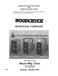
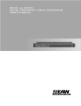
Tel: 01553 691122
Fax: 01553 691447
Website: www.fosterrefrigerator.co.uk
E-mail: [email protected]
a Division of ITW (UK) Ltd.
F/FMIC/SM/03/03
By Appointment to
Her Majesty Queen Elizabeth II
Suppliers of Commercial Refrigeration
Foster Refrigerator (UK) Ltd King’s Lynn
Service Manual
Service Manual
Foster Refrigerator
Oldmedow Road, King’s Lynn,
Norfolk PE30 4JU
England
F200 & F300
Modular Ice Cuber
&
FMIC 180 & 260
Electronic Modular Ice Cuber
F200 & F300 Modular Ice Cuber
CONTENTS - F200 & F300
1.
Page
4
4
4
4
SPECIFICATION
1.1 Capacities
1.2 Installation Notes
1.3 Stacking Installation
INSTALLATION INSTRUCTIONS
5
2.
START UP CYCLE
2.1 Start Up Cycle
2.2 Freezing Cycle
6
6
6
3.
HARVEST CYCLE
6-7
4.
OPERATION
4.1 Refrigeration During Freezing
4.2 Water System During Freezing
4.3 Ice Harvest Cycle
4.4 Water System During Ice Harvest Cycle
4.5 Control Sequence
7
7
7
7
7
7-8
5.
ALARM CONDITIONS
8
6.
P.C. BOARD SET UP
6.1 Water Error
6.2 Too High Condensing Temperature
8
8
8
7.
COMPONENT DESCRIPTION
7.1 Front Console Panel
7.2 P.C. Board
7.3 Compressor Contactor
7.4 Ice Thickness Sensor
7.5 Magnetic Switch
7.6 Hot Gas Valve
7.7 Condenser Temperature Sensor
7.8 High Pressure Control
7.9 Water Regulating Valve (water cooled models only)
7.10 Water Distribution System
7.11 Water Drain Solenoid Valve
7.12 Thermostatic Expansion Valve
7.13 Water Pump
7.14 Water Inlet Solenoid Valve (male fitting)
7.15 Water Level Sensor
8.
WIRING DIAGRAM
10
9.
SERVICES DIAGNOSTICS
11
10.
MAINTENANCE, CLEANING AND SANITATION
10.1 Icemaker
10.2 Ice Storage Bin
10.3 Cabinet Exterior
10.4 Cleaning Ice Maker
12
12
12
12
12
2
9
9
9
9
9
9
9
9
9
9-10
10
10
10
10
10
10
FMIC 180 & 260 Electronic Modular Ice Cuber
CONTENTS - FMIC 180 & 260
Page
1.
SPECIFICATIONS
13
2.
FOR THE INSTALLER
2.1 Important operating requirements
2.2 Select location
2.3 Ice machine
2.4 Final check list
14
14
14
14
14
3.
FOR THE PLUMBER
3.1 Conform to all applicable codes
3.2 Water Inlet
3.3 Drains
15
15
15
15
4.
FOR THE ELECTRICIAN
4.1 Electricial Connections
15
15
5.
START-UP
5.1 Start-up
15
15-16
6.
OPERATION
6.1 Refrigeration during freeze
6.2 Water system
6.3 Refrigeration system during harvest
6.4 Water system
6.5 Control sequence
16
16-17
17
17
17
17-18
7.
SERVICE SPECIFICATIONS
7.1 Component
7.2 Operating characteristics
7.3 Freeze cycle
7.4 Harvest cycle
18
18
18
18
18
8.
COMPONENT DESCRIPTION
18-19
9.
REMOVAL AND REPLACEMENT PROCEDURES
20-21
WIRING DIAGRAMS - FMIC 180 & FMIC 260
22
10.
SERVICE DIAGNOSIS
23
11.
MAINTENANCE AND CLEANING INSTRUCTIONS
11.1 Ice maker
11.2 Ice storage bin
11.3 Cabinet exterior
11.4 Cleaning (Ice maker)
23
23-24
24
24
24
12.
ASSEMBLY INSTRUCTIONS OF CONVEYOR KITS FOR
ICE MACHINES TO BE FITTED ON STORAGE BIN
24-25
13.
WIRING DIAGRAM CONCERNING THE CONNECTION
OF UPPER ICE MAKER MICRO TO CONVEYOR KIT MICRO
25
14.
GUIDELINES FOR ICEMAKER BIN LIDS
25
3
F200 & F300 Modular Ice Cuber
1.
Specification
1.1
Capacities
Output (kg/ 24 hours)
Bin Storage Capacity (kgs)
Cubes Per Cycle (kgs)
Standard Cube Size
Cycle Time (minutes)
Amps start/run
Watts Consumption
Machine Weight net / gross (kgs)
Refrigerant
Refrigerant Charge
Discharge Pressure Freeze Cycle
High Pressure Cut Out
High Pressure Safety Switch
Suction Pressure Freeze Cycle
Compressor Amps Freeze Mode
Voltage
Reservoir Water Level
Water inlet Connection
1.2
F200
F300
215
150/ 210
2.3
24mm x 24mm x 26mm
16
29/5.5
1000
70/85
R404A
500 grms
Max 17 bar/ Min 15 bar
30 bar
Cut in 20 bar/ Cut Out 33 bar
Start 3.6 bar/ End 2.3 bar
Start 4.2 amps/ End 3.4 amps
230/50/1
40mm to 45mm
3
/4 gas
320
150/210
2.3
24mm x 24mm x 26mm
11
31/8.5
1600
73/88
R404A
850 grms
Max 18 bar/ Min 16 bar
30bar
Cut in 20 bar/ Cut Out 33 bar
Start 3.6 bar/ 2.5 bar
Start 7.0 amps/ End 5.2 amps
230/50/1
40mm to 45mm
3
/4 gas
Fig.4
13.
Fig.5
Fig.6
Wiring Diagram Concerning The Connection Of Upper Ice Maker Micro
To Conveyor Kit Micro
1. Detach the light blue (No.13) cable of the upper ice maker; this cable is connected to the NC contact (usually closed) of the micro.
Connect it to the light blue (No.14) cable which is joined to the NO contact (usually opened) of the conveyor kit micro.
2. Connect the brown (No.16) cable which comes from the COM (common) contact of the conveyor kit micro to the NC contact (usually
closed) of the upper ice maker micro.
Installation Notes.
Allow 15cm minimum space at the sides and back for ventilation.
Bin Installation
The F200 and 300 fit the New SB150 Bin.
The F200 and F300 can be fitted to the New SB210 Bin but a KN311 Lid is required.
The F200 and F300 can be fitted to the Old SB150 Bin but a SB150 frame is required, as the F200 and F300 are smaller than the Old SB150
Bin.
The F200 and the F300 can be fitted to the Old SB210 Bin provided the KN310 lid is fitted first. However it is necessary to re-drill the lid to
secure the machine to it.
1.3
Stacking Installation.
To stack a Modular Cuber onto the present one, first remove the top panel from the lower machine.
Add a bead of food grade silicone sealer to the top edges of the lower units freezing compartment.
Lift the top machine onto the bottom machine, (the use of a mechanical lift is recommended).
Align the two machines, and using the two screws supplied in the hardware package supplied with the top machine, fasten the two together
through the fixing holes on either side of the machines.
Fit the Stacking Kit KS into the bottom machine as per the instructions supplied with the kit.
Using food grade silicone sealer, seal the edges between the freezing compartments of the top and bottom machine so as to avoid any
possible leakage of water through the join.
14.
Guidelines for Icemaker Bin Lids
SB 150 BIN
NO BIN LID
SB 210 BIN
KN 310 BIN LID
SB 150 BIN
NO BIN LID
SB 210 BIN
KN 310 BIN LID
SB 150 BIN
NKF 200 BIN LID
SB 210 BIN
NKF 310 BIN LID
SB 210 BIN
NKF 310 BIN LID
FMIC 180 HEAD
FMIC 260 HEAD
FMIF 220 HEAD
FMIF 550 HEAD
4
25
5. Check and tighten all bolts and screws.
6. Check for water leaks and make corrections.
7. Check the bin control to test shut-off.
Holding the evaporator deflector in open Position for more that 30secs, should cause the ice maker to shut-off at the end of harvest cycle.
Once the evaporator deflector is released in its closed position, the ice maker will restart.
8. Check cube size, adjust if required through setting screw of ice thickness control sensor.
9. With unit out of operation, clean the condenser using vacuum, cleaner, whisk broom or brush.
Instruct customer to clean condenser frequently DO NOT USE A WIRE BRUSH.
11.2
Ice Storage Bin
The interior liner of the bin is in contact with a food product, ice, and should be cleaned regularly. Once a week clean with soap and water,
and after that a hot water rinse and dry thoroughly. Commercial food grade sanitisers are available, and may be used.
11.3
Cabinet Exterior
Wipe clean unit and bin cabinet exterior with a clean cloth or disposable paper wipers, soaked in warm water with mild detergent solution.
11.4
Cleaning - Ice Maker
WARNING - Ice Machine Cleaner contains Phosphoric and Hydroxyacetic acids. These compounds are corrosive and may cause
burns. If swallowed, DO NOT induce vomiting. Give large amounts of water or milk. Call physician immediately. In case of
external contact, flush with water.
KEEP OUT OF THE REACH OF CHILDREN.
1.
2.
3.
4.
5.
6.
7.
8.
9.
10.
11.
Empty bin of ice.
Remove front panel.
Switch the Master switch power line and Unit Toggle switch OFF
Remove evaporator cover deflectors by lifting-up and pulling-up.
Switch the Master switch power line ON. Pour 200grs of Ice Machine Cleaner into the reservoir and put the unit toggle switch to
WASH position. Run unit for 15 minutes.
Using correct brush clean the interior of each evaporator egg-crate using the cleaning solution from the water reservoir.
Switch to OFF, remove the drain plug from the water reservoir to flush cleaning solution out of the reservoir. Replace the plug and allow
fresh water through float valve to fill-up the reservoir to thoroughly rinse it.
Repeat the reservoir flushing out two or three times.
Switch the toggle switch to ICE position.
Replace the evaporator cover deflector and front panel.
Check the next batch of cubes to be sure all the cleaner has gone (no sour taste).
CAUTION: DO NOT use ice cubes produced from the cleaning solution. Be sure none remains in the bin.
Installation Instructions
Before bringing the icemaker into action
perform the following operations:
preface
Warning!
It is expressly forbidden for the users of
the equipment to carry out the following
operation or those marked by the symbol, Such operations must be performed
exclusively by qualified personnel.
1. Electrical connections
2. Water mains connections
3. Machine installation
4. Machine test run
5. Repairing machine components and parts
6. Disassembly of machine and/or
components
7. Adjustment and setting procedures
8. Machine cleaning and maintenance relative
to the following parts and components:
Electrical, Electronic, Mechanical,
Cooling System
general specifications
Models 200 KG, 300 KG,
The icemaking machines
are approved by VDE, GS
and the relative symbols
are put on the packing,
serial plate and body of
the machine (Fig.10).
Fig 10.
12. Pour hot water into the storage bin to melt the cubes, and to also clean the bin drain.
12.
Assembly Instructions of Conveyor Kits for Ice Machines
to be fitted on Storage Bin
1. Fit the cover kit on the storage bin of 300kg (as indicated in Fig. 1) and put the lower ice maker on the bin as indicated in the instruction
manual.
2. Remove the cover and the 4 bushes (No.3) of the lower ice maker (Fig. 2), then apply the support gaskets No.4.
3. Remove the front and the 2 lateral panels of the lower ice maker and fit the conveyor support No.5 (Fig. 3).
4. Fit the conveyor kit (No.7 - Fig. 4).
5. Apply the upper ice maker after having removed the front and the 2 lateral panels and fix it to the lower ice maker through 2 screws on
the lateral edges.
6. Hook the shoot conveyor (No.10 - Fig. 6) at the edge of the upper ice maker water pan and fix it to the vertical conveyor No.7, previously
fitted on the lower ice maker (as indicated on Fig. 6).
7. Connect the upper ice maker micro to the conveyor kit as explained on Fig. 5 and on the enclosed wiring diagram.
8. Place back the panels previously removed.
OUR PRODUCTS ARE GOVERNED BY EC
LOW VOLTAGE DIRECTIVE 73/23/EEC EMC - 89/336/EEC AND THE COVER OF
THE MANUAL IS MARKED ACCORDINGLY.
Fig.3
Fig 20.
3) Clean the inside of machine and storage bin by
means of a warm water and sodium-bicarbonate
dampened sponge; rinse with plain water and dry
thoroughly.
4) Locate the icemaker and
the storage bin in the final
place, making sure that the
two are perfectly level, in
order to obtain an even
distribution of the water all
over the evaporator and a
uniform filling of the cube
plate (Fig.13).
The storage bin is equipped
with adjustable feet, which
allow for easy levelling and
sufficient height for cleaning
under the machine.
1 Note
Before installing the machine make
sure that:
a) the room temperature must not fall
below 10˚c (50˚F) or above (100˚F).
b) the water conductivity value must not
be below 10 µs/cm.
c) the main water temperature must not
fall below 5˚C (40˚F) or above
35˚C (95˚ F).
Fig 11.
Fig.2
Fig 1.
2) Match the icemaker to
its storage bin, fixing them
with the two screws
supplied with the machine
(Fig.20).
installation
d) the main water pressure
must not fall below
1bar. (14 PSI) or above
5 bar. (70 PSI). If
pressure is above 5 bar.
a pressure regulator
should be fitted to
the water supply to the
machine (Fig.11)
Fig.1
1) Check that ice cuber has
not been damaged during
transportation (Fig.1)
e) machine is
away from
sources of heat
and in a
sufficiently
ventilated area.
A distance of at
least 20cm must
be allowed
between the
sides, back and
the walls of the
machines
(Fig.12, Fig.14).
f) the machine will
not work with
demineralized
water.
11) Fit the flexible drain pipes to the
icemaker and the storage bin ensuring
there is adequate fall on the pipes to avoid
the drain water backing up. For a perfect
water outlet from the machine a minimum
incline of 3% of the pipes is advisable.
Check also that the pipes are not throttled
or siphoned. It is advisable that the pipes
discharge in an open vented drain (Fig.18).
12) Connect the
machine to the
electricity supply
after having
Fig 13.
checked that the
voltage corresponds
to that on the plate
on the rear panel of
Fig 5.
the machine (Fig.5).
The maximum voltage variation should not
exceed ± 6% of that stated on the rating
plate. A fused isolator must be included in
the electrical circuit to the machine, with its
own bipolar main switch at least 3 mm. of
contacts opening. The machine should be
connected to a suitable power supply with
earth terminal.
Fig 17.
Fig 16.
5) Unlock the sensor and the baffle by removing
the transit packaging 1and tape 2, which have
been applied to avoid any damage during
transportation (Fig.16 & Fig.17).
6) The icemaker has been designed for coupling
with another icemaker, which can be installed on
the top of the first one. For this installation, a kit
can be supplied upon request. It contains all
necessary assembling instructions.
Fig 24.
7) Do not put the machine in a dusty
environment as this could cause a fast build up of
dust etc, therefore effecting the efficient working
of the condenser (only for air-cooled models).
8) Never keep food, bottles or other things in the
bin in order to avoid the stored ice becoming
tainted.
9) Connect machine to the water supply first and
then to a suitable electricity supply.
Fig 12.
Fig 14.
2
24
10) Connect the
3/4" Feeding pipe
(supplied) to the
machine and to the
cold drinking water
supply line. It is
advisable to install a
shut-off valve (not
supplied) to the
water feed pipe. If
the feed water
contains impurities,
the installation of a
filter system is
recommended. If the
Fig 18.
water is particularly hard, i.e.
rich in minerals and their derivatives, the
application of a suitable water filter is
recommended, preventing any scale
deposits blocking the water circuit of the
machine (Fig.18).
5
13) Air deflector installation. (Fig.24) The
deflector has to be installed in order to
prevent the re-circulation of hot air to the
condenser.
2.
2.1
Start Up.
10.
The table below is intended as a quick reference to aid the Service Agent to determine the cause of a particular type of malfunction, as well
as the recommended repair. It is not intended to be an exclusive list.
Reference to other portions of this manual including wiring diagrams, installation, and operation are recommended to better determine the
cause of a problem.
Start–up Cycle.
Open the water valve and switch on the power to the machine.
The machine enters the Start-Up mode with the energising of the PC Board with the green LED (Power On) illuminated.
It is necessary to remove the front cover of the machine to see all of the LED’s.
The Green LED of Machine In Operation is also energised, blinking fast for 40 seconds prior to the start up of the machine.
Power On.‘Green’.
Bin Full/ Washing. ‘Amber’.
Machine in Operation ‘Green’.
Alarm ‘Red’.
High Pressure. ‘Red’.
Symptom
Possible cause
Correction
Machine does not run at all.
Master switch open.
Hi-pressure safety switch open W.C.
E.C. board inoperative.
No power to unit.
Test and replace.
Test and replace.
Remove board and check.
Check electrical source.
Machine does not run.
Bin full of ice
N.C. contacts of control switch open.
Magnetic switch inoperative.
Interface P.C. Board inoperative.
None
Check and replace.
Check and replace.
Check and replace.
Machine does not run.
The harvest cycle time is too long causing
safety device to trip-off unit
Press the ‘reset’ push button to resume
operation and check freezing and harvest time.
Machine runs, compressor does not.
Toggle switch open in ICE position.
Compressor contactor open.
Compressor relay open.
Compressor winding open.
Test and replace.
Test and replace.
Test and replace.
Test and replace.
Machine runs, makes no ice.
No water in reservoir
Water, but not pumping.
Water pumping but does not cool.
Check water supply and float valve.
Check power to pump, replace pump.
Check refrigeration system pressure, check
system for leak, check condenser
condenser for clog, or poor air circulation,
check compressor. Test and replace relay, must
be energised to freeze.
Machine runs, makes ice, does not try to
harvest
Ice thickness control open
Check sensor fingers are not covered with scale
sediment.
Check and replace P.C. Board.
Reset / Washing. ‘Push Button’.
During the start up cycle the following components in operation are.
Hot Gas Valve.
Water drain valve.
Water pump.
•
•
•
2.2
Service Diagnosis
Freezing Cycle.
After the Start Up cycle the machine enters directly into the Freezing cycle with the following components in operation:
Water Inlet Valve
Compressor
Fan Motor (running continuous for the first three minutes).
The LED’s energised are:
Machine Power On.
Machine in Operation (constant).
Water is coming into the water reservoir through the Water Inlet Solenoid Valve until it reaches the maximum level controlled by the Water
Level Sensor.
After 30 seconds the Water Pump starts up.
3 minutes after the start of the freeze cycle the Water Inlet Solenoid Valve is activated for a few seconds until the water reaches the
maximum level, this is to reduce the possibility of slush ice formation.
In the meantime the condenser sensor starts to transmit the current to the PC Board keeping in operation the Fan Motor in ON-OFF mode
or continuously according to the condenser temperature.
•
•
•
•
•
Note: Do not remove the evaporator deflector, as it will cause the switching off of the machine at ‘FULL STORAGE BIN’.
The machine remains in the freezing cycle with the ice becoming thicker until the two metal fingers of the Ice Thickness Sensor (energised
at low voltage) are covered by the water cascading over the front surface of the ice plate.
If the contact between the two metal fingers remains established (by the water) for more than 10 seconds power is transmitted back to the
PC Board and the machine enters into the Harvest Cycle mode depending on:
Fan motor in ON-OFF Mode during the previous freezing cycle.
If the Condenser Sensor detects a rise in temperature to 38°C (due to high Ambient) the length of the freezing cycle is extended by 30
seconds before entering the harvest mode.
Fan motor running CONTINUOUSLY during the previous freezing cycle.
Goes straight into the harvest mode.
The first freezing time will range between 15 and 20 minutes. Freeze time will be longer if the ambient temperature is above 25°C and
shorter if it is below 25°C. The Average cycle time is about 22 minutes.
Built-in transformer for ice thickness control
open.
Built-in relay on P.C. Board open.
Check and replace P.C. Board.
Machine runs, makes and harvests ice,
but very slowly.
Low refrigerant charge.
Check system, repair leak weigh in charge.
Low ice capacity.
High discharge pressure due to notcondensable or overcharge.
Inefficient compressor.
Condenser dirty.
Low water pressure (water-cooled).
High air temperature (air cooled)
Evacuate and weigh in charge.
Low water supply.
Water pump not running.
Plugged water distributor.
TXV super heat wrong.
Refrigerant charge low.
Check float valve not maintaining proper
water level in reservoir.
Check and repair or replace.
Clean machine.
Adjust or replace.
Adjust - check or leak. Recharge.
Hot gas valve coil open.
Hot gas valve will not open.
Test and replace hot gas valve.
Test and replace hot gas valve.
•
•
3.
Harvest Cycle
Machine makes irregular ice.
Machine runs, makes ice, but does not
harvest..
During the harvest cycle the components in operation are:
Hot Gas Valve.
Water Drain/Purge Valve.
Water Pump for the first 40 seconds.
Compressor.
And both of:
Power On LED.
Machine In Operation LED.
30 seconds from the start of the harvest cycle, the Water Inlet Solenoid valve is
energised for ten seconds to allow fresh water into the sump whilst the pump is in
operation.
The Fan Motor remains in OFF mode unless the condenser probe detects a rise in
temperature above 38°C (Same as per the freezing cycle).
When the Ice Plate falls down from the evaporator, the magnetic switch is activated
sending a signal back to the PC Board to start a new freeze cycle.
Check the cubes from the first harvest to determine if any adjustments are required:
If any adjustments are needed either turn IN or OUT the screw shown as 1 in the
illustration.
The screw position (factory set at 6mm) determines the distance between the sensor
fingers and the front of the evaporator therefore setting the ice cube thickness.
•
•
•
•
•
•
NOTE: This type of machines produces an “Ice Plate” that breaks when it falls into the storage bin. Setting the ice thickness
sensor to have single ice cubes may cause the machine to malfunction.
6
11.
Replace.
Clean.
Check and repair.
Check temperature of air entering condenser.
Maintenance and Cleaning Instructions
A FOSTER Ice System represent a sizable investment of time and money in any company’s business. In order to receive the best return for
that investment, in MUST receive periodic maintenance.
It is the USER’S RESPONSIBILITY, and less costly in the long run, to avoid possible down time by keeping it clean, adjusting it as needed
and by replacing worn parts before they can cause failure. The following is a list of recommended maintenance that will help keep your
machine running with a minimum of problems.
Maintenance and Cleaning should be scheduled at a MINIMUM of twice per year.
11.1
Ice Maker
THE FOLLOWING MAINTENANCE SHOULD BE SCHEDULED AT LEAST TWICE A YEAR ON THIS ICE MAKER. CALL YOUR
AUTHORISED SERVICE AGENCY
1. Check and clean or service any optional water treatment devices, if any are installed.
2. Clean water strainer.
3. Check that the cabinet is level, in the side-to-side and front-to-back directions.
4. Clean the water system, evaporator plate and sump assembly, using a solution of Ice Machine Cleaner. Refer to CLEANING - Ice
maker.
NOTE: Cleaning requirements vary according to local water conditions and individual user operation. Continuous checking of
the clarity of ice cubes and visual inspection of the water system parts, evaporator plates and the sump assembly before and after
cleaning will indicate frequency and procedure to be followed in local areas.
23
Check the second and third cube harvest. Ensure that they are the correct size and make adjustments to the Ice Sensors Fingers as
necessary. In certain areas where there are extreme water problems it may be necessary to fit a filter or purifying equipment.
Wiring Diagrams
NOTE. To ensure a correct operation of the machine the water must have a minimum electrical conductivity level of 20 us.
Open the bottom end of the plastic ice deflector for 30 seconds to check the operation of the magnetic switch. The machine will switch OFF
and the Amber LED will glow to indicate machine OFF at full storage bin. Releasing the deflector will restart the machine in the freezing
mode commencing with the 3-minute delay.
Replace all panels and screws previously removed.
4.
Operation
A
B
C
D
E
F
G
–
–
–
–
–
–
–
Power
Terminal block
Contactor
Compressor
Toggle switch
Pressostat
Ice sensor
H – N.C. Microswitch /
Magnetic Switch
L – Electronic card
M – Fan motor
N – Motor pump
O – Water drain valve
P – Hot gas valve
180 + 260 Wiring Diagram
Air Cooled 220 V. 50 Hz 1 ph
Colour of the Cables
m – Brown
bc– Light blue
gv– Yellow green
b – White
n – Black
r – Red
NOTE. If the water is too soft (demineralized) the Ice Thickness Sensor may not be able to sense the water on its fingers, thereby
not switching the unit onto the harvest cycle. In the event of this occurring a safety system built into the PC Board will automatically
switch the unit into the harvest mode if the freezing period goes beyond 30 or 40 minutes.
4.1
Refrigeration during freezing.
This ice machine employs either air (standard) or water (optional) as a condensing media, the refrigeration system for either one is as
follows:
The refrigerant metering is by thermostatic expansion valve.
4.2
Water System during freezing.
A combination of the water inlet solenoid valve and water level sensor is used to control the level of the water in the reservoir/sump.
30 seconds from the start of the freeze cycle the water pump starts, forcing water to the top of the evaporator where it is distributed through
the water tube and then cascades over the surface of the evaporator by gravity. Some of the water will turn to ice with the remainder
returning to the water reservoir for redistribution over the evaporator.
4.3
Ice harvest cycle.
When the ice reaches the desired size, as determined by the fingers of the ice thickness sensor, the hot gas bypass valve is energised
allowing the hot gas to warm the evaporator resulting in the ice cube block falling into the storage bin below.
4.4
Water system during ice harvest cycle.
During the harvest cycle, the electric water drain valve is energised opening the drain line. All of the water remaining in the reservoir at the
end of the freezing cycle is pumped, out to drain, through the water solenoid valve during the last 40 seconds of the defrost cycle eliminating
any possible build-up and accumulation of mineral concentration and other impurities in the reservoir.
The water inlet valve is energised for the last 10 seconds whilst the pump is running to allow fresh water to rinse the reservoir.
When the ice cube block is released from the evaporator it causes the deflector to swing open sufficiently to reset the contactor of the
magnetic switch which, via the PC Board, de-energises the water drain valve initiating a new freezing cycle.
The harvest/defrost cycle lasts between 1 and 2 minutes.
4.5
Control sequence.
At the start of the freezing cycle the contacts of the magnetic switch, mechanically operated by deflector cover, are closed via the PC Board,
thereby closing the circuit to the main contactor coil and consequently the compressor, fan motor and after 30 seconds the water pump.
As the ice reaches the thickness required the film of water flowing over it makes contact with the ice thickness sensor fingers (energised at
low voltage). If contact is maintained for more than 10 seconds a relay on the PC Board is energised controlling simultaneously the hot gas
valve and the water drain valve.
A
B
C
D
E
F
G
–
–
–
–
–
–
–
Power
Terminal block
Contactor
Compressor
Toggle switch
Pressostat
Ice sensor
H – N.C. Microswitch /
Magnetic Switch
L – Electronic card
M – Fan motor
N – Motor pump
O – Water drain valve
P – Hot gas valve
180 + 260 Wiring Diagram
Water Cooled 220 V. 50 Hz 1 ph
Colour of the Cables
m – Brown
bc– Light blue
gv– Yellow green
b – White
n – Black
r – Red
REFRIGERATION SYSTEM SCHEMATIC
NOTE: In the event of failure of the ice thickness sensor, the PC Board automatically turns the unit into the defrost cycle when the
freezing cycle reaches 30 or 40 minutes depending on the operation of the fan motor during the freezing cycle.
At this point the unit initiates the defrost cycle. The hot gas circulating into the evaporator serpentine causes a slight melting of the ice cube
22
7
block releasing it from the mould. Once released the ice block drops into the storage bin below and breaks into individual cubes, in the
process it moves the deflector plate forwards. The defector has on its side a magnetic switch that when it moves forward it opens and closes
the contacts. This motion deactivates the relay contacts that control the hot gas and water drain valve allowing the unit to start a new
freezing cycle.
When the ice bin is full of ice, the last batch of ice released from the evaporator cannot continue into the bin and so it stops the deflector from
returning to its position. With the magnetic switch contacts remaining open for more than 30 seconds the entire unit stops with the glowing
of the Amber bin full LED.
The machine will restart when the deflector returns to its normal position provided the machine has been of for more than 3 minutes, if not
the start will be delayed for 3 minutes with the blinking of the green Machine In Operation LED.
5.
Alarm Conditions
Power On.‘Green’.
To replace the drier:
1. Remove the factory seals from the replacement drier and install the drier in the refrigerant lines with the arrow positioned in the direction
of the refrigerant flow.
2. Solder the drier into the lines, two places, taking precautions NOT TO OVERHEAT the drier body, during installation soldering.
3. Purge the system and check for leaks.
4. Thoroughly evacuate the system to remove moisture and non- condensables.
5. Charge the system with refrigerant, by weight. SEE NAMEPLATE.
6. Replace and attach front and left side panel.
9.10
Bin Full/ Washing. ‘Amber’.
Machine in Operation ‘Green’.
CAUTION: If the factory seal is broken on the replacement drier, exposing it to the atmosphere for more than a few minutes, the
drier will absorb moisture from the atmosphere and lose substantial ability for moisture removal.
Alarm ‘Red’.
Remove front and top panels.
Store refrigerant charge in liquid receiver and isolate parts to be opened from the rest of the system.
Disconnect water distributor tube above the evaporator plate and remove it.
Unsnap and remove evaporator cover deflector.
Loosen and remove all screws securing the evaporator frame to the chassis.
Unsolder and remove the refrigerant lines at the top of the evaporator plate to be replaced.
Remove nuts at top and left and right side of the evaporator to remove top and side trimming that make-up the frame of the evaporator
plate. The evaporator plate is now free.
To replace the evaporator plate, reverse the removal procedures. See nameplate. Weight in proper charge of R22/R404A.
Reset / Washing. ‘Push Button’.
The two Red LED’s are glowing constantly.
Condenser Sensor faulty.
9.11
The two Red LED’s are blinking fast.
Reset Mode. Charging water through the Water Solenoid Valve after tripping OFF on Water Error.
The Red Alarm LED is glowing continuously.
Harvest cycle longer than 3 minutes 30 seconds.
9.12
Red High Pressure LED is glowing continuously.
Too High Discharge Pressure, exceeding 33 bar (460 PSI).
6.
PC Board Set Up
The PC Board can be set up for Manual Reset Mode with the Jumper In Place.
Manual Reset Mode. (Jumper in place)
To Restart the Machine it is necessary to Push the Reset Button.
The PC Board can be set up for Automatic Reset Mode with the Jumper Out Of Place.
Automatic Reset Mode. (Jumper out of place)
The Automatic Reset Mode is activated only for the following ALARM CONDITIONS.
WATER ERROR
TOO HIGH CONDENSING TEMPERATURE
TOO LONG HARVEST CYCLE.
Thermostatic Expansion Valve
1. Remove front, top and right side panels.
2. Purge system of refrigerant.
3. Unsweat valve at inlet, equaliser, and outlet.
4. Remove insulation from valve bulb, remove mounting straps and valve from cabinet.
5. Place new valve bulb in same place as old valve, secure with straps, and reinsulate.
Reverse to reassemble.
The Red Alarm LED is blinking fast.
Reset Mode: Condenser Sensor sensing condenser temperature below 50°C, fan motor in operation for 3 minutes then back on to Start Up
Cycle Mode.
Red High Pressure LED is blinking fast.
RESET MODE: After pushing the Red Reset Button of the Pressure Control (located at the rear of the machine) firstly the fan motor runs for
3 minutes then back on to the Start Up Cycle Mode.
The PC Board also checks the maximum time of the freeze cycle that may change according to the operation of the fan motor during the
freezing cycle (relative to room temperature).
Fan motor in ON/OFF Mode: Maximum Freeze Cycle length equal to 30 minutes.
Fan motor ON All of the time: Maximum Freeze Cycle length equal to 40 minutes.
Whenever the machine remains in the Freezing Cycle for the Maximum time ( 30 or 40 minutes) the PC Board moves the unit directly into
the Harvest Cycle.
Water Regulating Valve - Water Cooled
1. Shut off water.
2. Remove front and right side panel.
3. Unscrew water inlet fitting connection at the water regulator valve to condenser bracket.
4. Purge system of refrigerant.
5. Unscrew fitting connection at outlet of valve.
6. Unsweat valve connection from ‘T’ joint on system liquid line.
7. Remove valve from machine.
Reverse to reassemble.
The two Red LED’s are blinking slowly.
Water Error. The water level inside the reservoir is to low after 3 minutes from start of the water inlet valve being activated.
The Red Alarm LED is blinking slowly.
Too High Condensing Temperature: The Condenser Sensor detected a temperature above 65°C.
Removal and Replacement of the Evaporator Plate Assembly
1.
2.
3.
4.
5.
6.
7.
High Pressure. ‘Red’.
NOTE: Always install a replacement drier, any time the sealed refrigeration system is opened. Do not replace the drier until all
other repair or replacement has been completed.
Thoroughly evacuate the system to remove moisture and non-condensables.
9.13
Fan Motor or Blade - Left and Right Side
1. Remove left or right side service panels.
2. Remove screws and fan motor shroud.
3. Unplug fan motor to be removed.
4. Remove fan motor bracket from upper tie rod of unit chassis.
5. Remove fan blade from motor. Note location on motor shaft, and hub position.
6. To also replace fan motor, remove it from bracket.
Reverse to reassemble.
NOTE: When replacing a refrigeration component, the exact refrigerant charge must be WEIGHED or metered into a completely
evacuated system, because the FMIC is a CRITICALLY charged system.
•
•
•
6.1
Water Error
The machine remains in OFF mode for 30 minutes then it tries to re-fill with water.
Fills with water: Machine remains in operation.
Fails to fill with water: Machine again in the OFF mode for a further 30 minutes.
6.2
Too High Condensing Temperature
As soon as the temperature registered by the Condenser Sensor is above 50°C, the PC Board starts up firstly the condenser fan motor for
3 minutes then the entire machine through the normal Start UP Cycle Mode.
After the 3 minutes 30 seconds of the Harvest Cycle, the PC Board moves the machine into a new Freezing Cycle.
8
21
9.
Removal and Replacement Procedures
WARNING Be sure the electrical power supply circuit breaker and the inlet water supply are OFF, BEFORE starting any of the
following REMOVAL AND REPLACEMENT procedures as a precaution to prevent possible personal injury or damage to equipment.
9.1
7.
Component Description
7.1
Front Console Panel
Power On.‘Green’.
1. Remove front panel.
2. Remove front interior metal strip.
3. Unplug pump.
4. Remove one screw holding pump bracket to reservoir right side.
5. Pull pump forward and lift up.
6. Remove discharge hose from pump outlet.
Reverse to replace.
9.2
Bin Full/ Washing. ‘Amber’.
High Pressure. ‘Red’.
Water Pump
Machine in Operation ‘Green’.
Alarm ‘Red’.
Reset / Washing. ‘Push Button’.
Reservoir
1. Close water valve on water supply line.
2. Perform above steps and remove water pump.
3. Remove reservoir drain plug and flush reservoir out.
4. Remove the float valve from the reservoir.
5. Remove screws securing reservoir.
6. Liff-up and pull forward to remove reservoir.
Reverse to replace.
9.3
Distributor/Water Tube
1. Remove front panel.
2. Locate water distributor at the top of the evaporator.
3. Pull distributor forward to unsnap it from its holding clamps.
4. Remove hose clamp and water hose.
Reverse to replace.
9.4
Outlet Water Valve
1. Remove front and right side panel.
2. Unplug water valve.
3. Remove clamp securing outlet tube to valve.
4. Remove hose clamp and hose from inlet fitting.
5. Remove two screws and nuts securing valve to its metal bracket and remove valve.
Reverse to replace.
9.5
7.2
1. Remove top panel (if possible), front panel, leff side service panel and left fan motor shroud.
2. Store refrigerant charge in liquid receiver.
3. Disconnect electrical lines from compressor.
4. Isolate parts to be opened from the rest of the system.
5. Remove compressor mounting bolts.
Reverse to reassemble.
NOTE: Always install a replacement drier any time the sealed refrigeration system is opened. Do not replace the drier until all
other repair or replacement has been completed.
9.6
Condenser - Air Cooled
7.3
1. Remove both side panels and remove screws of condenser bracket.
2. Store most of refrigerant charge in liquid receiver.
3. Isolate parts to be opened from the rest of the system.
4. Cut or unsweat liquid and discharge lines.
5. Unbolt and remove condenser from unit rear side.
Reverse to reassemble.
9.7
9.8
7.4
Ice Thickness Sensor.
Located in the front upper right side of the evaporator, the sensor is constructed of two metal reeds through which passes current at a low
voltage. The two metal reeds, which are individually insulated, are set, through a setting screw, to maintain a minimum clearance from the
evaporator (3 to 6mm). Once ice is formed in the moulds plus sufficient to bridge the minimum clearance between the two sensor reeds and
the evaporator, the water flowing over the evaporator makes contact between the two sensors. If contact is made for 10m seconds the P.C.
Board receives the signal and starts the defrost cycle.
7.5
Magnetic Switch.
Located in the plastic deflector plate, in front of the evaporator, the switch sends a pulse to the P.C. Board which switches the machine back
into the freezing cycle.
7.6
Remove front, right side panel and right fan motor shroud.
Unplug hot gas valve.
Purge system of refrigerant.
Cut or unsweat valve, remove from machine.
To replace, heat sinking the valve is CRITICAL. Wrap the replacement valve in wet rags, and sweat into place. Leave rags on until joints
cool.
Reverse steps 3-1 to reassemble.
7.7
20
Condenser Temperature Sensor.
The condenser temperature sensor probe (located in contact with the condenser coil) detects the condenser temperature variations and
signals them to the P.C Board at low voltage.
In the air cooled versions, in relation to the different current received, the microprocessor of the P. C. Board supplies, through a TRIAC, the
power at high voltage to the condenser fan motor to cool the condenser and reduce the temperature.
If the condenser temperature rises and reaches 65°C (150°F) the current passed to the micro processor is such to cause an immediate and
total stopping of the operation with the blinking of the Red Alarm LED.
Removal and Replacement of the Drier
To remove the drier:
1. Remove front and left side panel.
2. Remove screws and remove left side fan motor shroud.
3. Store most of the refrigerant charge in liquid receiver.
4. Unsolder refrigeration lines at both ends of the drier and remove the drier.
Hot Gas Valve
The Hot Gas Solenoid Valve functions only during the Harvest Cycle, to divert the Hot Discharge Gas from the Compressor, bypassing the
Condenser and Expansion Valve, for a direct flow to the Evaporator to release the ice cubes from the moulds.
The Hot Gas Solenoid Valve is comprised of two parts, the Body and Plunger and the Coil Assembly. Installed in the discharge line from the
compressor, the energised coil lifts the valve stem within the body to cause the hot gas to be diverted when the ice Thickness Sensor signals
the P.C. Board to start the Harvest Cycle.
Hot Gas Valve
1.
2.
3.
4.
5.
9.9
Compressor Contactor.
Located in the control box, the compressor contactor function is to carry the compressor line current. The contactor is wired to receive power
from the P.C. Board.
Condenser - Water Cooled
1. Shut-off water.
2. Remove front and left side panels.
3. Store most of refrigerant charge in liquid receiver.
4. Isolate parts to be opened from the rest of the system.
5. Unsweat water and refrigerant lines.
6. Unbolt and remove condenser.
Reverse to reassemble.
P. C. Board.
Located in the control box, this board is the brain of the system as it governs the ice machine cyclematic through sensors, relays and
switches. It consists of two separated printed circuits one at high and the other at low voltage integrated with a fuse, four connectors for the
sensors/ switches. (Condenser sensor – BLACK-, Magnetic switch- GREEN-, ice thickness sensor- RED-, water level Sensor- BLUE), two
jumpers (one J1 for factory use only – and the second J2 for the selection between manual or automatic reset mode). One outlet connector
(front LED display- BLACK ), one serial port connector (BLACK) and four plug in terminals for input and output power. With J2 closed the
P.C. Board is set up for Manual reset mode. When J2 is open the P.C. Board is set up for Automatic Reset mode.
The P.C. Board includes a electronic safety timer that turns on the unit automatically to the defrost cycle when the freeze cycle is longer than
30 or 40 minutes and trips off the unit when the defrost cycle is longer than 3 minutes and 30 seconds (red alarm LED on).
A trimmer, located close to the transformer, can be used to change the current received from the Ice Thickness Sensor in relationship to the
Electrical Conductivity of the water.
Compressor
7.8
High Pressure Control.
The High Pressure Control, safety control, is factory set to cut out at 30 bar and cut in at 22 bar. The control functions as a precautionary
device to shut OFF electrical power to the machine should a loss of water occur, to water-cooled machines condenser, or the failure of the
9
Condenser Fan Motor on the air-cooled versions. The high Pressure Control is manual reset with the reset button at the on the rear of the
machine and a monitoring Red LED on the Front Console Panel.
7.9
8.3
Water Regulating Valve (water-cooled models only).
The water Regulating Valve function is to maintain a constant Compressor head pressure by regulating the amount of water flowing through
the condenser, on water-cooled models. The valve operates through the refrigeration system high-pressure side. Rotating the adjusting
screw, located at the top of the valve, will Increase or Decrease the water flow through the water-cooled condenser, which in turn will
Decrease or Increase the Compressor operating head pressure.
7.10
7.11
8.4
8.5
Water Drain Solenoid Valve.
Thermostatic Expansion Valve.
The Thermostatic Expansion Valve regulates the flow of refrigerant to the evaporator and reduces the pressure of the liquid refrigerant from
condensing pressure to evaporating pressure.
7.13
Water Pump.
NOTE: In case the Interface P.C. Board does not receive the second pulse from the microswitch/magnetic switch, after 30 to 32
seconds from the first pulse, it will send a signal to the main Board, to switch the unit from defrost to freezing cycle.
It is possible to vary the maximum waiting time for starting a new freezing cycle after the pulse sent by the first switch, by
adjusting a ‘trimmer’. The waiting time variation ranges from 22 to 45 seconds.
The water pump primes the water from the reservoir to the distributor tube and through the holes (in the distributor) it cascades over the
evaporator moulds by gravity to be frozen into clear ice cubes. The water pump remains OFF during the first 30 seconds of the freezing
cycle whilst it continues to run for the first 40 seconds of the defrost/ harvest cycle to drain the remaining water in the reservoir.
7.14
Water Inlet Solenoid Valve (male fitting).
8.6
The P.C. Board energises the Water Inlet Solenoid Valve during the beginning of the freezing cycle until the water reaches the maximum
level in the reservoir (controlled by the Water Level Sensor).
After 3 minutes, from the start of the freezing cycle, the Water Inlet Valve is energised again for a short period to re-fill the reservoir to the
maximum level to minimise the possibility of slush ice forming.
A flow control is fitted in the feed pipe to reduce the pressure of the water.
7.15
8.
Wiring Diagram - F200 & F300
8.7
=
=
=
=
=
=
=
8.8
A
B
C
D
E
F
G
H
I
J
K
L
M
N
O
P
-
Q
-
RC CS CM -
High Pressure Control - Water Cooled Models
The High Pressure Control, a safety control, is factory set to cut-out, at 20 bar and cut-in at 13 bar. The control functions as a precautionary
device to shut OFF electrical power to the Ice maker, should a loss of water occur to the water cooled Condenser. In addition to being a
manually reset Control, there is an adjusting screw for raising or lowering the CUT-IN pressure.
8.9
brown
light blue
yellow green
white
black
red
orange
High Pressure Fan Control - Air Cooled Models
A reverse acting automatic reset, high pressure control is electrically connected to the two condenser fan motors and by a capillary tube to
the liquid line.
Its function is to maintain the head pressure during the freezing cycle between the preset values and the head pressure during the harvest
cycle ensuring sufficient heat to release the cubes from the cube moulds.
The control contacts are set to open at 13 bar cutting off the electrical power supply to the fan motors and to close at 15 bar.
F200 - F300 Wiring Diagram
220V 50Hz 1ph
M
bc
gv
b
n
r
a
Hot Gas Solenoid Valve
The Hot Gas Solenoid Valve functions only during the Harvest Cycle, to divert the hot discharge gas from the Compressor, bypassing the
Condenser and thermostatic expansion valve, for direct flow to the Evaporator Platen Assembly to release ice cubes from the ice cube
moulds.
The Hot Gas Solenoid Valve is comprised of two parts - the Body/Plunger and the Coil assemblies. Installed in the discharge line of the
Compressor, the energised solenoid coil liffs the valve stem within the valve body to cause the hot discharge gas to be diverted when the ice
Thickness sensor has signalled to the P.C. Board to start the Harvest Cycle.
Water Level Sensor.
The Water Level Sensor, located in the upper right side of the reservoir, works in conjunction with the P.C. Board in order to control the water
level at the beginning of the freeze cycle by receiving a low power current through the water. When the current reaches the P.C. Board the
water inlet solenoid valve is de-energised.
If the P.C. Board doesn’t receive any signal from the Water Level Sensor within the first 3 minutes of the freeze cycle the P.C. Board trips
OFF the operation of the machine with the switching ON of the two Red LED’s blinking slowly.
N.C. Microswitch/Magnetic Switch
Signalling the ice cubes release. Located in the upper left side corner of the evaporator, this low voltage switch - single pole/single throw mechanically operated by the evaporator deflector actuator, signals to the P.C. Board the end of the defrost cycle and to re-start a new
freezing cycle. The swinging motion, to which the ice deflector is subject to when the ice cubes drop into the bin below, causes the deflector
actuator to press (open the contact) and the release (close the contact) microswitch plunger. This OFF and ON situation of the N.C. contact
is enough to signal to the P.C. Board that the timed defrost cycle is over. On later models the sequence is controlled by a magnetic switch
attached to the bottom right hand side of the deflector.
If the bin is full of ice, the evaporator deflector will be left in the open position by the last batch of released cubes. This means that the
deflector actuator will keep the N.C. microswitch plunger pressed,or the magnet and switch separated, as long as the deflector remains in
open position.
If the N.C. contact are open for more that 30 seconds, the switch signals to the built-in time delay of the P.C. Board to turn the unit OFF
The Water Drain Solenoid Valve functions in conjunction with the water pump to flush-out the reservoir assembly at the beginning (first 40
seconds) of every harvest cycle. This action cleans-up and rinses the reservoir during each harvest cycle preventing dangerous water
mineral concentration.
7.12
Ice Thickness Sensor
Located in the front upper right side off the evaporator, the sensor is made with two metal reeds in which passes power at low voltage. The
two metal reeds, which are individually insulated, are set, through a setting screw, to maintain a minimum clearance from the evaporator
(7mm) Once ice is formed into each mould and is thick enough to fill-up that minimum clearance existing between the two sensor reeds, and
the evaporator, the water that cascades over the ice has gradually increased to make contact between the two sensor reeds.
Contact remains there for about 6 seconds the P.C. Board receives the signals to put the ice machine on defrost.
Water Distribution System.
The Water Distribution System functions to evenly supply water to all of the cells of the evaporator plate. The water is pumped from the water
reservoir to the distributor, above the evaporator, through the holes and flows over the ice moulds. Gravity returns the unfrozen water to the
reservoir for recirculation.
Compressor Contactor
Located in the control box, the compressor contactor functions is to carry the compressor line current. The contactor is wired to receive
power from the ICE/OFF/WASH switch through the P.C. Board.
Water Regulator Valve - Water Cooled Models
The Water Regulator Valve functions maintain a constant Compressor head pressure, by regulating the amount of incoming water flowing
through the Condenser, on water-cooled models. The valve operates through the refrigerant system high side pressure.
Rotating the adjusting screw located on top of the valve, can INCREASE or DECREASE the water flow through the water-cooled Condenser,
which in turn, will DECREASE or INCREASE the Compressor operating head pressure.
8.10
Water Distribution System
The Water Distribution System functions is to evenly supply water to all cells of the evaporator plate. The water pump pumps water from the
sump to the tee.
From there water is channelled through the vertical tygon tube to the water distributors, above the evaporator plate, and from the holes in the
distributor tube water flows to the cells on one side of the evaporator plate.
Gravity flow returns the unfrozen excess portion of water to the sump reservoir for recirculation.
Input terminal board
Compressor contactor
Compressor
Ice sensor
End defrosting switch
Water level sensor
Condenser temperature probe
Led card
P.C. Board
HI pressure switch
Manual/Automatic reset jumper
Water pump
Water inlet valve
Water drain/purge valve
Hot gas valve
Fan Motor
(only AIR cooled unit)
Fan Motor
(only WATER cooled unit)
Compressor relay
Start capacitor
Run capacitor
8.11
Water Outlet Solenoid Valve
The Water Outlet Solenoid Valve functions in conjunction with the water pump to flush-out the sump assembly at every harvest cycle.
This action cleans-up and rinses the sump during each harvest cycle preventing dangerous water mineral concentration.
8.12
Thermostatic Expansion Valve - TXV
The Thermostatic Expansion Valve regulates the flow of refrigerant to the evaporator and reduces the pressure of the liquid refrigerant from
condensing pressure to evaporating pressure.
10
19
At this point, the unit initiates the defrost cycle. The hot gas circulating into the evaporator serpentine causes a slight melting of the ice cubes
which get released from their moulds. Once entirely released the ice cubes drop simultaneously into the ice storage bin below; in doing so
they move apart from the evaporator bottom end of the plastic deflector. This plastic deflector has on its upper left corner a metal actuator
which, on account of the deflector’s swinging motion, caused by the ice dropping in the bin, pushes the microswitch plunger to open and
close the N.C. contacts. This will, in turn, de-activate the relay contacts that control the hot gas and water drain valve which get de-energised
allowing the unit to start a new freezing cycle. On later models the sequence is controlled by a magnetic switch attached to the bottom right
hand side of the deflector.
When the ice bin is full of ice, the last batch of ice cubes released from the evaporator accumulates to keep the bottom end of the plastic
deflector in open position; with the N.C. microswitch/magnetic switch contact open for longer than 30sec the entire unit stops.
7.
Service Specification
In servicing a machine, it is offen useful to compare individual units operating characteristics to those of a normally operating machine. The
data that follows gives those characteristics; however, be aware that these values are for a NEW, CLEAN machine. USE THESE NUMBERS
AS A GUIDELINE ONLY.
COMPONENT
Reservoir level
Cube Size Control Ice Sensor
distance from evaporator
High Pressure Safety Switch
Water-cooled
Fan Pressure Control
Air-cooled only
7.1
R22 - R404A Machines
30-35 mm
C/IN 13 bar - C/OUT 20 bar
The table below is intended as a quick reference to aid the service engineer to determine the cause of a particular malfunction as well as the
recommended repair. It is not intended to be an exclusive list.
Reference to other portions of the manual inclusive of wiring diagrams, installation and operating instructions are recommended to better
determine the cause of a problem.
Symptom
Possible cause
Correction
Warning RED LED ON
No Warning RED LED ON
See Page 20.
P.C. Board inoperative
No power to machine
See Page 20.
Remove board and check.
Check electrical source.
Bin Full Amber LED ON
Bin Full of Ice.
Magnetic Switch inoperative
None.
Check and replace.
Machine Runs but compressor not running.
P.C. Board compressor relay open.
Compressor Contactor open.
Compressor relay open.
Compressor Winding open.
Test and Replace.
Test and Replace.
Test and Replace.
Test and Replace.
Machine runs, makes ice,
does not try to harvest.
Ice thickness control open.
Check sensor fingers to determine if covered
with scale or sediment.
Water electrical conductivity must be higher
than 20 uS.
Machine will not run with demineralized water.
Check and replace P.C. Board.
Water Too soft
C/IN 15 bar - C/OUT 13 bar
Operating Characteristics
Freeze Cycle
R22 Machines
2.8/2.5 bar
14 bar
13 bar
1.5/1.3 bar
20/25 Minutes
5.5
7.6
4.4
4.6
1.5
Suction Pressure at the beginning of the Freeze Cycle
Average Discharge Pressure A/C
Average Discharge Pressure W/C
Suction Pressure at the end of the Freeze Cycle
Freeze Time
Amps. drawn at the beginning of the Freeze Cycle FMIC 180
Freeze Cycle FMIC 260 Beginning
Amps. drawn at the end of the Freeze Cycle FMIC 180
Freeze Cycle FMIC 260 End
Suction Pressure at the end of the Freeze Cycle
7.3
Service Diagnosis.
7mm
On air-cooled models during the freezing cycle the discharge pressure is maintained between 13 and 15 bar by means of fan pressure
control and at the same time, the suction pressure will also decline reaching its lowestpoint just before harvest. Compressor amps experience
a similar drop.
On water-cooled models the discharge pressure is constantly maintained during the freeze cycle by the water regulating valve at 13 bar.
However, suction pressure and compressor amps, will still decline as the machine freezes ice.
7.2
9.
R404A Machines
3.5 bar
15.5 bar
17 bar
1.7 bar
20/25 Minutes
5.0
8.0
4.0
5.5
1.7
Built in relay on P.C. Board open.
Machine runs makes ice and
harvests ice but very slowly.
Low Refrigerant Charge.
Check system for correct refrigerant charge.
Check system for leak.
Low ice capacity
High discharge pressure due to under
condensing or refrigerant overcharge.
Inefficient Compressor.
Dirty condenser.
Low water flow (water cooled only).
High air temperature (Air-cooled only).
Reclaim refrigerant and recharge with the
correct amount.
Replace compressor.
Clean Condenser.
Check and repair.
Check temperature of air entering condenser.
Machine makes irregular ice.
Water distributor blocked.
Expansion valve superheat wrong.
Low refrigerant charge.
Clean water distributor.
Adjust or replace.
Check for leak, reclaim refrigerant and
recharge with correct amount.
Harvest Cycle
R22 Machines
R404A Machines
Average Discharge Pressure
9 bar
13/15 bar
Average Suction Pressure
7.5 bar
7.5 bar
The values listed are representative of values seen at a wide range of air and water temperatures and are for a normal cube size. When
comparing these figures to field data, allow a variation from each end of the range given.
Refrigerant charge
Model
Air cooled
Water cooled
Refrigerant metering device
Expansion valve
R22 Machines
FMIC180
FMIC260
l000gr
l500gr
650gr
700gr
R404A Machines
FMIC180
FMIC260
1200gr
1700gr
1200gr
900gr
NOTE: Always check nameplate on individual ice machine for special refrigerant charge before charging the refrigeration system.
Such refrigerant charge is the average charge for the Modular Cubers. However, it is important to check nameplate for each
machine.
8.
8.1
Component Description
Toggle Switch - ICE/OFF/WASH
Is a double pole-double throw switch. In OFF position keeps the electric circuit open through the P.C. Board built-in ON-OFF switch. In ICE
position the unit electric circuit is closed for normal operation of electric component.
In WASH position opens the electric circuit to the compressor contactor and fan motors and closes the circuit for the water pump.
8.2
Electronic Control Board
Located in the control box, this board is the brain of the system as it governs the ice machine cyclematic through sensors, relays and
switches. The sensor is the ice thickness control which signals to the P.C. Board to energise the built-in relay that controls the Hot Gas Valve
and Water Drain Valve. The other contactor to which the P.C. Board supply power is on the compressor line.
The switches are: the Toggle ICE/OFF/WASH switch and the N.C. microswitch/magnetic switch actuated by the evaporator deflector that
signals to the P.C. Board that ice has been defrosted and released, so that the relay controlling the defrost can be disconnected.
The P.C. Board is equipped with an electronic safety timer that turns-on automatically the unit to defrost cycle when the freezing cycle is
longer than 40 minutes and trips-off the complete unit when defrost cycle is longer then 4 minutes.
18
11
10.
The thermostatic expansion valve meters how much liquid refrigerant is to be allowed into the evaporator section of the refrigeration system.
This is determined by the temperature of the TXV sensing bulb, located on the suction line manifold, at the outlet of the evaporator.
If the bulb senses a warm suction line, more refrigerant is allowed into the evaporator, (common at the beginning of the freeze cycle) and
when the temperature begins to fall, less refrigerant is allowed through. This is why the suction side gauge pressure will decline throughout
the freeze cycle. At the evaporator, the liquid refrigerant released from high pressure, boils off in the low pressure environment and absorbs
heat, thus cooling the evaporator surface and anything near it, such as water.
The low pressure refrigerant vapour then is forced through the heat exchanger where any excess liquid refrigerant boils-off, allowing only
refrigerant vapour to enter the compressor suction tube, where it is recompressed into high pressure, high temperature gas again and the
cycle repeats.
Maintenance, Cleaning and Sanitation Instructions.
The Foster Modular Ice Cuber represents a sizeable investment of time and money in any company’s business.
In order to receive the best return for the investment periodic maintenance is essential.
It is the USER’S RESPONSIBILITY to see that the machine is maintained and the following is a list of recommended instruction to keep the
machine running with a minimum of problems.
Maintenance and Cleaning should be scheduled at the minimum twice per year while sanitation at least once per month.
10.1
Icemaker
THE FOLLOWING MAINTENANCE SHOULD BE SCHEDULED FOR AT LEAST TWO TIMES PER YEAR ON THE ICE MAKER AND
SHOULD BE CARRIED OUT BY YOUR AUTHORISED SERVICE AGENT.
Check and clean or service any optional water treatment devices, if installed.
Clean water strainer.
Check that the cabinet is level, checking from front to back and side to side.
Clean/ Sanitise the water system, evaporator plate and water reservoir using a solution of Citric Acid. (refer to Cleaning Icemaker).
6.2
Water System
A fixed charge of water had been brought into the machine during the harvest or defrost cycle through the float valve.
A pump, running continuously, forces the water to the top of the evaporator, where it is distributed through a water tube and then cascades
down the evaporator surface by gravity. As it flows across the refrigerated evaporators, some of the water will be chilled enough to change
form, turn to ice, and stay frozen onto the evaporator. Most of the water returns to the reservoir, to be sucked back into the pump, and
repumped over the evaporators.
Note: Cleaning/ Sanitising requirements vary according to local water conditions and individual user operation.
Continuous checks of the clarity of the ice cubes and visual inspection of the water systems parts, evaporator plate and the
reservoir before and after cleaning will indicate frequency and procedure to be followed.
Check and tighten all bolts and screws.
Check for water leaks and secure as necessary.
Check the bin control to test shut off. Holding the evaporator deflector in the open position for more than 30 seconds should cause the ice
machine to hut off. Once the deflector has been returned to the closed position the ice making process will restart.
Check cube size, make adjustments to the ice thickness sensor as necessary.
Switch the machine OFF clean the condenser using a vacuum cleaner, brush between the fins using a soft brush. DO NOT USE A WIRE
BRUSH. Instruct the user to clean condenser frequently.
10.2
Ice Storage Bin
The interior of the ice storage bin is in contact with food products, ICE, and should be cleaned and sanitised regularly. Once a week sanitise
it with a commercial food grade sanitiser in compliance with the manufacturer instruction.
10.3
Cabinet Exterior.
Wipe clean the machine and ice bin exterior with a clean cloth or tissue soaked in a mild solution of soapy water.
10.4
Cleaning Ice Maker
Empty the bin of ice.
Remove the front panel.
Wait till the end of the defrost/harvest cycle then push and hold the RESET BUTTON for 6 to 8 seconds. The machine will stop with the
blinking of the Amber LED (slow blink)
Pour 100gr of citric acid directly into the reservoir then push the RESET BUTTON again for a short while. The water pump starts to operate
with the fast blinking of the Amber LED, the water inlet valve will be energised till the reservoir is full.
After 15 minutes push the RESET BUTTON for a short while. The P.C.Board will put the machine in automatic rinsing mode with the Amber
LED blinking (blinking twice and then repeat).
NOTE: Rinsing mode consists of:
(a) Energising the water drain valve and the water pump for 40 seconds to empty the reservoir.
(b) De-energise the water drain valve and the water pump for 1 minute.
(c) Energise the water inlet valve till the reservoir is full.
(d) Energise the water pump for 1 minutes.
The above sequence is repeated 7 time so as to be sure that all traces of citric acid have been removed.
At the end of the 7th rinsing cycle the P.C>Board stops the operation of the machine and the Amber LED will be blinking slowly.
Push and hold the reset button for 6 to 8 seconds the machine will restart in the freezing mode.
Replace the evaporator deflector and front panel.
Check the next batch of ice to be sure all of the cleaner has gone (no sour taste).
6.3
Refrigeration System During Harvest
The refrigeration system performs the harvest of ice by use of a hot gas bypass valve. When the time comes to de-ice the evaporators, the
hot gas valve is energised, and the high temperature, high pressure gas bypasses the condenser, and is allowed directly into the evaporator.
The high pressure gas is cooled by the cold evaporator so it condenses into a liquid, giving up its heat as it does so. This heat warms the
evaporator and the ice frozen onto the evaporator surface melts, releasing the frozen cubes. Ice then falls by gravity into the storage bin.
The liquid refrigerant goes through the suction line into the heat exchanger where it boils-off so that only refrigerant vapour is drawn into the
suction tube of the compressor.
6.4
Water System
During the harvest cycle, the electric water drain valve is energised thereby opening the drain line.
All water remaining in the reservoir at the end of freezing cycle is pumped-out, to the waste, through the water solenoid and drain line during
the entire defrost cycle eliminating any possible build-up and accumulation of minerals concentration and impurities in the water reservoir.
As the pump stops, the incoming water, passing through the float valve, has still sufficient time, before beginning the next freezing cycle, to
properly fill up the sump/reservoir, so that there would not be any cavitation problem when the water pump resumes its operation, granting
thereby a beffer ice formation inside the cooling cells.
When the released ice cubes drop into the bin, they open-up for a fraction of a second the bottom end of the plastic deflector.
The deflectors swinging motion is enough to reset the contact of the N.C. microswitch/magnetic switch which - via electronic control board
- de-energises the water drain valve allowing the unit to initiate a new freezing cycle.
Caution- DO NOT use ice cubes produced from the cleaning solution. Ensure none remain in the storage bin.
Pour hot water into the storage bin to melt any cubes that may remain and to also clean the bin drain.
NOTE: If the interface P.C. Board does not receive the pulse from the second microswitch/magnetic switch, after 30-32 seconds
from the first pulse it will send the signal to the main Board, to switch the unit from defrost to freezing cycle.
The harvest cycle lasts about 1 1/2 to 2 minutes.
6.5
Control Sequence
At the start of the freezing cycle, the N.C. contacts of the microswitch/magnetic switch mechanically operated by the actuator plate of the
deflector cover are closed,- via electronic control board, - closing the circuit to the main contact or coil and consequently to the compressor,
fan motors and to the water pump motors.
Then, as the ice thickness reaches the value that corresponds to the full cube size, the film of water that constantly cascades over the slab
of ice formed on the evaporator, arrives to establish a contact between the two fingers (energised at low voltage) of the ice sensor control,
located on the front upper right side of the evaporator. If the contact between the two fingers of the ice sensor remains established - by the
film of water - for more than 10 seconds, a small relay on the electronic board energises, controlling simultaneously both the hot gas valve
and the water drain valve.
NOTE: In case of failure of the ice level sensor the P.C. Board automatically turns the unit to the defrost cycle if the freezing cycle
is longer than 40 minutes.
12
17
Check operation of the freezing cycle:
a) Compressor is operating.
b) Water pump is operating as seen by water moving through the tygon tube up to
the water distributor at the top of evaporator plate, where water is uniformly
dispensed and cascades down over the egg-crate evaporator and drains back
into the Sump Assembly for recirculation.
4. Remove the evaporator deflector cover temporarily and feel inside the ice cube mould of the egg-crate evaporator, this should feel cold
to the touch, shortly after ice will begin to form.
First freezing cycle will range between 20 and 25 minutes. Longer for temperature above 25°C and shorter when temperature is below 25°C
Average complete cycle time is about 25 minutes.
5. Make sure of correct operation of float valve and water pump.
6. Check for any irregular noise source and if any, eliminate it.
7. Replace plastic cover deflector before harvest cycle.
8. Observe first ice cube harvest.
a) Check operation of N.C. microswitch/magnetic switch on models controlling the
ice maker operation by keeping open the bottom end of the plastic deflector for
more than 30 seconds.
b) Check size of ice cubes; if an adjustment is required thread down or out screw
N. 1 as shown in the illustration.
This screw position determines the distance between the sensor reeds and the
egg-crate evaporator thus keeping the ice cube at a proper thickness.
9. Observe second and third cube harvest.
Check if size and shape combination is correct.
In areas where extreme water problem conditions exist, filtering or purifying equipment
is recommended.
NOTE: If water used is too soft, ‘demineralised’ the ice thickness sensor might
not be able to sense the water on its reeds, thereby it will not switch the unit on
harvest cycle.
A safety system built in the E.C. board switches the unit on harvest cycle whenever
the freezing period gets longer than 40min.
10. Replace all cabinet panels and screws previously removed.
11. Thoroughly explain to owner/user the significant specifications of the ice maker start-up, reset and operation, going through the procedures
in the operating instructions.
Answer all questions about the ice maker by the owner and inform the owner himself of the name and telephone number of the
authorised service agency serving him.
6.
FMIC 180 & 260 Electronic Modular Ice Cuber
1.
Specification
FMIC180
1
2
20mm — WATER OUTLET
20mm — WATER OUTLET –
WATER COOLED ONLY
3
/4in GAS WATER INLET
CORD SET
3
4
Accessories:
KSC 18 — Cube stacking kit
Dimensions:
HEIGHT
530mm (207/8in)
WIDTH
800mm (311/2in)
DEPTH
600mm (253/8in)
WEIGHT 77kg
FMIC 180 Machine Specifications - R22 Machines
Model
Cond. unit
FMIC 180
Air
Water
Basic
electr.
Model
FMIC 180A
FMIC 180W 220-240/50/1
Finish
Comp.
Stainless Steel
amps
6
5.5
30
28
980
810
FMIC 180 Machine Specification
R404A Machines
300
1920*
1
Electric
power
cons. kWh
Watts per 24hr
Start
amps
Water reg.
It/24hr
24
20
No. of
wires
Amps
fuse
3 x 2.5mm2
15
Cond unit
Finish
Comp
Water
consumption
Air cooled
Stainless steel
11/4
16 litre per hr
Basic
Electr.
Amps
Start
amps
Watts
Elec Power
Cons. kWh
per 24hr
Fuse
Amps
230/50/1
6
30 A
1100
26.4
16 A
Cubes per Harvest: 204 Full
* Subject to variations according to different water and ambient temperature conditions. (Amb. 32°C – Water 15°C)
Operation
FMIC260
1
2
20mm — WATER OUTLET
20mm — WATER OUTLET –
WATER COOLED ONLY
3
/4in GAS WATER INLET
CORD SET
3
4
Accessories:
KSC 25 — Cube stacking kit
Dimensions:
HEIGHT
680mm (263/4in)
WIDTH
800mm (311/2in)
DEPTH
600mm (253/8in)
WEIGHT 100kg
FMIC 260 Machine Specifications - R22 Machines
Model
Cond. unit
Finish
Comp.
FMIC 260
Air
Water
Stainless Steel
1.5
Model
REFRIGERATION SYSTEM SCHEMATIC
6.1
Refrigeration During Freeze
This ice machine employs either air or water as a condensing media, the refrigeration system for either is as follows:
At the hermetic compressor, Refrigerant is compressed into a high temperature, high pressure gas.
This gas contains the heat removed from the evaporator, as well as compressor motor heat. The gas moves through the discharge line
into the condenser, air or water-cooled. If air-cooled, the discharge pressure will change with the heat load and the ambient air temperature.
If water-cooled, the discharge pressure is controlled by the amount of water flowing through the condenser - which is determined by the
water regulating valve.
After the gas is cooled in the condenser, giving up much of its heat, the gas condenses into a high pressure liquid. This liquid travels through
the liquid line to the metering device, a thermostatic expansion valve.
16
Basic
electr.
FMIC 260AS
220-240/50/1
FMIC 260W
amps
Start
amps
7.5
6.5
50
48
Electric
power
cons. kWh
Watts per 24hr
1450
1230
37
35
FMIC 260 Machine Specification
R404A Machines
Water reg.
It/24hr
400
2400*
No. of
wires
Amps
fuse
3 x 2.5mm2
Cond unit
Finish
Comp
Water
consumption
Air cooled
Stainless steel
2
19.5 litre per hr
Basic
Electr.
Amps
Start
amps
Watts
Elec Power
Cons. kWh
per 24hr
Fuse
Amps
230/50/1
9
49 A
1600
38.4
16 A
20
Cubes per Harvest: 289 Full
* Subject to variations according to different water and ambient temperature conditions. (Amb. 32°C – Water 15°C)
Freeze Cycle R404A Machines
Model
Discharge
Pressure
Suction
Pressure
FMIC 180
13/15 Bar
1.3 Bar
FMIC 180
18/20 Bar
1.5 Bar
Evap
Temp
-10 /
-23°C
-6 /
-20°C
Ambient
Temp
Model
Discharge
Pressure
Suction
Pressure
21°C
FMIC 260
14/17 Bar
1.3 Bar
32°C
FMIC 260
18/20 Bar
1.5 Bar
13
Evap
Temp
-10 /
-23°C
-6 /
-20°C
Ambient
Temp
12°C
32°C
2.
For The Installer
3.
For The Plumber
2.1
Important Operating Requirements
3.1
Conform To Applicable Codes
MINIMUM
Air Temperature
10°C (50°F)
Water Temperature
5°C (40°F)
Water Pressures
1 bar gauge
Electrical Voltage
Variations Voltage
Rating Specified on Nameplate
–10%
3.2
2.2
MAXIMUM
38°C (100°F)
38°C (100°F)
5 bar gauge
+10%
1.
Switch
Extended periods of operation exceeding these limitations constitute misuse under the terms of manufacturer’s Limited Warranty, resulting
in a loss of warranty coverage.
2.
Electrical socket
INSTALLATION NOTE: Allow 15cm minimum space at sides and back for ventilation and utility connections.
3.
Electrical plug
Select Location
4.
Water inlet
The first step in installing the equipment is to select the location. The purchaser of the unit will have a desired spot in mind, ensure that it is:
indoors, in an environment that does not exceed the air and water temperature limitations for the equipment.
that the necessary utilities are available including the correct voltage electrical power.
that there is space around the installed machine for service, 15cm minimum left, right, and rear for air-cooled models.
5.
Shut-off valve
6.
Water filter
7.
water outlet line
8.
Bin water outlet line
9.
Open vented water drain
10.
Water outlet from the condenser: water cooled version only
•
•
•
2.3
Water Inlet
AIR-COOLED MODELS: The recommended water supply is cold water, 3/4in O.D. copper tubing, connected a -3/4in gas - male fitting at
the back of the cabinet. Install a hand operated valve near the machine to control the water supply.
Ice Machine
The use of a mechanical lift is recommended for lifting the uncrated ice maker onto the bin.
Place the unit directly onto the bin, align the panels so that the unit is even with the back, left and right sides of the of the bin. Locate the
hardware package, take out two mounting screws, and use them to secure the ice maker to the bin. See illustration A below.
Remove all shipping material, note the locations of the ice sensor and ice deflector. Remove ice sensor protection 1 and masking tape 2
from ice deflector. See illustrations B & C below.
A.
B.
C.
When choosing the water supply for the Foster Cuber, consideration should be given to:
A) Length of run.
B) Water clarity anf purity.
C) Adequate water supply pressures.
Since water is the most important single ingredient in producing ice you cannot over emphasise the three items listed above. Low water
pressure, below 1 bar may cause malfunction, of the ice maker unit. Water containing excessive minerals will tend to produce cloudy
coloured ice cubes, plus scale build-up on parts in the water system.
Heavily chlorinated water can be controlled using charcoal or carbon filters.
3.3
Drains
AIR-COOLED MODELS: There is one 20mm dia sump drain fitting at the back of the cabinet, the drain lines are gravity type, and 3% fall is
recommended. Insulation in high humidity areas is recommended. There must be a vent at the highest point of the drain line, and the ideal
drain receptacle would be a trapped and vented floor drain.
WATER-COOLED MODELS: Besides the above drain, a separate condenser drain must be run. Connect it to the -3/4in gas - condenser
drain connection at the back of the cabinet.
STORAGE BIN: A separate gravity type drain needs to be run, similar to the air-cooled sump drain. insulation of this drain line is recommended.
2.4
Final Check List
1. Is the cabinet/bin level?
2. Is the cuber in a location where ambient temperatures are a minimum of 10˚C (50˚F) all year round and will not exceed a maximum of
40˚C (100˚F).
3. Is there at least a 15cm clearance behind and around the cabinet for all connections and for proper air circulation?
4. Have all electrical and piping connections been made?
5. Has the electrical power supply wiring been properly connected and the voltage tested and checked against the nameplate rating? Has
the unit been properly grounded.
6. Is the water supply line shutoff valve installed and opened and has the inlet water supply pressure been checked to ensure a minimum
of 1 bar without exceeding a maximum of 5 bars.
7. Have the compressor hold down bolts been checked to be sure the compressor is snug on the mounting pads.
8. Check all refrigerant lines and conduit lines to guard against vibration and possible failure.
9. Have the cuber and the bin been wiped clean with clean damp cloths?
10. Has the owner/user been given the User Manual and instructed on how to operate the ice maker and the importance of periodic
maintenance?
11. Has the owner/user been given the name and telephone number of the Authorised Foster Distributor or Service Agency serving him?
4.
For The Electrician
The unit comes equipped with an electrical cord for power supply. The lead wires must be connected to an electrical plug that corresponds
to the local electrical codes and requirements or to a separate two pole isolator with opening to the contacts of about 3mm.
The isolator should be placed close to the selected ice maker.
Undersized wiring or incorrectly installed electrical circuit will result in major problems and malfunctions.
Voltage variations should not exceed ten per cent.
IMPORTANT: All plumbing and electrical connections must be made by licensed plumbers and electricians, and must follow the
electrical specifications printed on the ice maker nameplate.
NOTE: All Foster Cubers require a neutral wire and a solid earth ground wire to prevent possible severe Electrical Shock Injury to
individuals or extensive damage to equipment.
5.
5.1
Start-Up
Start-Up
1. Remove the screws and pull the Front Panel out.
2. Check that the Master ICE/OFF/WASH toggle switch is in the OFF position on the
Control Box side.
3. Open the water supply line shut-off valve.
NOTE: Observe that the inlet water can be seen flowing into the Sump Assembly.
Allow water to fill the Sump, about three minutes, until the water is at the correct
level. The float should cause the water to stop a few mm from reservoir overflow.
When the water has filled the Sump Assy, and has forced all of the trapped air out of
Water Pump and pump tube, therefore preventing the pumping of water filled with air
bubbles.
DO NOT start Water Pump when the Sump Assy is filling with water. WAIT until the
Sump is filled. Put unit under power by moving the power line switch to ON position.
Move the toggle switch to ICE position. Third and fourth ‘LEDs’ on console panel will
glow respectively indicating that unit and compressor are under electric power.
14
15