1
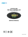
(Including Bin Information)
ISO 14001
Service Manual
F132, 202 & 302
Modular
Ice Cubers
ISO 9001
(Issued August 2011)
Contents
Contents
Manual Information & Health & Safety Notes
Environmental Management Policy
Disposal Requirements
Modular Cuber & Bin Details
Indicator & Buttons
Start up & Freezing Cycle
Harvest Cycle
Operation of the unit – An In-depth Description
Alarm Conditions & PC Board Set up
Component Description
Maintenance & Cleaning
Wring Diagram
LED Warning/Standard Troubleshooting &
Notes
Page
1
2
2
3
4
4 to 5
5 to 6
7 to 9
10 to 11
11 to 15
15 to 16
17 to 18
19 to 21
Service Manual Information
The products and all information in this manual are subject to change without prior notice.
We assume by the information given that the person(s) working on these refrigeration units are fully trained and
skilled in all aspects of their workings. Also that they will use the appropriate safety equipment and take or meet
precautions where required.
The service manual does not cover information on every variation of this unit; neither does it cover the installation
or every possible operating or maintenance instruction for the units.
Health & Safety Warnings and Information
Make sure the power supply is turned off before making any electrical repairs.
To minimise shock and fire hazards, please do not plug or unplug the unit with wet
hands.
During maintenance and cleaning, please unplug the unit where required.
Care must be taken when handling or working on the unit as sharp edges may cause
personal injury, we recommend the wearing of suitable PPE.
Ensure the correct moving and lifting procedures are used when relocating a unit.
Do NOT use abrasive cleaning products, only those that are recommended. Never
scour any parts of the refrigerator. Scouring pads or chemicals may cause damage by
scratching or dulling polished surface finishes.
Failure to keep the condenser clean may cause premature failure of the
motor/compressor which will NOT be covered under warranty policy.
Do NOT touch the cold surfaces in the freezer compartment. Particularly when hands
are damp or wet, skin may adhere to these extremely cold surfaces and cause frostbite.
Please ensure the appropriate use of safety aids or Personnel Protective Equipment
(PPE) are used for you own safety.
1
Environmental Management Policy for Service Manuals and Duets.
Product Support and Installation Contractors
Foster Refrigerator recognises that its activities, products and services can have an adverse impact upon the
environment.
The organisation is committed to implementing systems and controls to manage, reduce and eliminate its adverse
environmental impacts wherever possible, and has formulated an Environmental Policy outlining our core aims. A
copy of the Environmental Policy is available to all contractors and suppliers upon request.
The organisation is committed to working with suppliers and contractors where their activities have the potential to
impact upon the environment. To achieve the aims stated in the Environmental Policy we require that all suppliers
and contractors operate in compliance with the law and are committed to best practice in environmental
management.
Product Support and Installation contractors are required to:
1. Ensure that wherever possible waste is removed from the client’s site, where arrangements are in place all
waste should be returned to Foster Refrigerator’s premises. In certain circumstances waste may be disposed
of on the client’s site; if permission is given, if the client has arrangements in place for the type of waste.
2. If arranging for the disposal of your waste, handle, store and dispose of it in such a way as to prevent its
escape into the environment, harm to human health, and to ensure the compliance with the environmental
law. Guidance is available from the Environment Agency on how to comply with the waste management ‘duty
of care’.
3. The following waste must be stored of separately from other wastes, as they are hazardous to the
environment: refrigerants, polyurethane foam, and oils.
4. When arranging for disposal of waste, ensure a waste transfer note or consignment note is completed as
appropriate. Ensure that all waste is correctly described on the waste note and include the appropriate sixdigit code from the European Waste Catalogue. Your waste contractor or Foster can provide further
information if necessary.
5.
Ensure that all waste is removed by a registered waste carrier, a carrier in possession of a waste
management licence, or a carrier holding an appropriate exemption. Ensure the person receiving the waste at
its ultimate destination is in receipt of a waste management licence or valid exemption.
6. Handle and store refrigerants in such a way as to prevent their emission to atmosphere, and ensure they are
disposed of safely and in accordance with environmental law.
7. Make arrangements to ensure all staff who handle refrigerants do so at a level of competence consistent with
the City Guilds 2078 Handling Refrigerants qualification or equivalent qualification.
8.
Ensure all liquid substances are securely stored to prevent leaks and spill, and are not disposed of to storm
drains, foul drain, or surface water to soil.
Disposal Requirements
If not disposed of properly all refrigerators have components that can be harmful to the environment. All old
refrigerators must be disposed of by appropriately registered and licensed waste contractors, and in accordance
with national laws and regulations.
2
Modular Ice Cuber Description
The modular ice cuber machines, with vertical evaporator, are specially designed for large scale user’s e.g. fast
food restaurants, discos, hotels and bars.
The vertical evaporator produces an ice sheet that when dropped into the bin, breaks into single die-shaped
cubes. Each storage bin is designed for the different models of modular ice maker.
For our models we supply three types of bin (as shown below).
Ice Bin Description
Ice Bin Graphics with and without Cuber Unit
SB100 (for F132)
Storage capacity up to 100kg
Dimensions: 565x810x1060 mm.
Heat-formed, food-safe polyethylene cell with
40mm polyurethane foam providing a high degree
of insulation.
The external construction is in stainless steel AISI
304.
The full width door, made of synthetic material,
makes the collection of the ice an easy and quick
operation.
SB150 (for F202 & F302)
Storage capacity up to 150kg.
Dimensions: 765x810x1060 mm.
Heat-formed, food-safe polyethylene cell with
40 mm polyurethane foam providing a high
degree of insulation.
The external construction is in stainless steel
AISI 304.
The full-width door made of synthetic material,
makes the collection of the ice a quick and easy
operation.
The image opposite shows the bin with the option
of two lids. Each unit comes with the correct lid for
the ice machine that is ordered as this is not a
separate part.
SB210 (for F202 & F302)
Storage capacity up to 210 kg.
Dimensions: 1075x785x980 mm.
Heat-formed, food-safe ABS plastic cell with
40 mm polyurethane foam providing a high
degree of insulation.
The external construction is in stainless steel
AISI 304.
The full-width door, made of synthetic material,
makes the collection of the ice an easy and
quick operation.
The image opposite shows the bin with the option
of two lids. Each unit comes with the correct lid for
the ice machine that is ordered as this is not a
separate part.
Each bin comes with four legs screwed into mounting sockets on the base. Each provides an 18.5cm minimum
height and among these four legs one has a levelling foot included.
3
Indicators and Buttons
Visible LED warnings/Buttons
Symbol
Reason
Button
Use
Tank Full/ Washing
Alarm
Reset/ Washing Button
High Pressure Alarm
LED warnings & Button underneath the front unitcover
Symbol
Reason
Button
Electrical Power
Supply
Use
Compressor
Start Up Cycle
1. Turn the water and electrical supply on when connected to the unit (See Installation and Operation
manual)
2. The unit enters the ‘Start Up’ mode with the PC board energized. The
Green LED indicates that the
unit is on, it is necessary to remove the front cover of the machine to see all the LED’s.
3. The
green LED which shows the machine is in operation will also be energised, blinking fast for 40
seconds prior to the start-up of the machine.
4. During the start up cycle the components in operation are:
Hot Gas Valve
Water Drain Valve
Water Pump
Harvest Assist solenoid (pusher F202 & 303 only)
Freezing Cycle
1. After the start up cycle the machine goes straight into the freezing cycle with the following components
energised:
Water Inlet Valve
Compressor
Fan Motor (In continuous operation for the first 3 minutes)
2. The LED’s that are on indicate the following:
Machine under Power
Machine in operation
(Steady), this will remain on at all times after starting.
4
3. Water is then released via the inlet solenoid valve into the reservoir until it is full to the maximum level.
The water level is controller by the water level sensor (shown in the images below).
4. 30 seconds after the water is released/collected into the reservoir the water pump will start.
5. After a few minutes (3-5) from the beginning of the freezing cycle, the water inlet solenoid valve is
activated again. This is activated for a few seconds to re-fill the water reservoir to its maximum level. It
does this to reduce any possibility of slush ice forming.
6. In the meantime the condenser sensor starts to transmit a current to the PC board. During this operation
the Fan Motor will be either in the ON/OFF mode or continuously according to the condenser
temperature.
NOTE – Do not remove the evaporator deflector cover as it will cause the unit to switch off and
state “Storage Bin Full”
warning LED to show.
7. While water runs over the two metal reeds of the thickness sensor, the ice forming on the evaporator
plate surface becomes thicker.
8. When the power is transmitted back to the PC board continuously through the metal reeds of the Ice
Thickness Sensor for more than 6 seconds, the machine enters into the Pre-Harvest mode or goes
directly into the Harvest Cycle mode. This is dependent on one of the following options being activated:
Fan Motor in ON/OFF Mode during the Previous Freezing Cycle.
Raise the cut in temperature of the condenser sensor to 38 ºC (Fan motor off) and extend the length of
freezing cycle by 30 seconds to then go into harvest cycle.
Fan Motor Always In Operation during the Previous Freezing Cycle.
Go straight to the harvest cycle.
The first freezing cycle will range between 13 and 17 minutes long. It will take longer if the water temperature is
above 25 ºC and shorter when the temperature is below 25 ºC.
The average complete cycle time is about 15 minutes.
Harvest Cycle
1. During the harvest cycle the components in operation are:
Hot Gas Valve
Harvest assist solenoid
Water Drain/Purge Valve
Water pump for the first 40 seconds.
Compressor
LED’s showing:
Machine under power
Machine in operation
(Steady), this will remain on at all times after starting.
2. 30 seconds after the beginning of the Harvest Cycle, the Water Inlet solenoid Valve is energised (for 10
seconds) this is activated in order to have a short flush of fresh water into the pump while the Water
Pump is still in operation.
5
3. The Fan Motor remains in the OFF mode unless the Condenser Sensor probe rises up to more then 38
ºC (this is the same set up as per the end of freezing cycle).
4. When the Ice Plate falls down from the evaporator, the magnetic switch on the evaporator plastic
deflector is activated for a while providing the signal to the PC board to restart a new freezing cycle.
5. Check the first ice cube harvest; check the size of the ice cubes; if an adjustment is required thread down
or out the screw as shown below.
This screw position determines the distance between the sensor reeds and the evaporator plate thus keeping the
ice cubes at the correct thickness
NOTE: Setting the ice thickness sensor in order to have single ice cubes to form may cause a
malfunction of the machine.
6. Observe the following second and third cube harvests. When produced check if the size and shape
combination are correct. In areas where hard water conditions exist, filtering or purifying equipment is
recommended for the relevant conditions.
NOTE: If water used is too soft or "demineralised" the ice thickness sensor might not be able to sense
the water on its reeds, meaning it will not switch the unit onto harvest cycle. A safety system built in the
P.C. Board switches the unit onto harvest cycle whenever the freezing period gets longer then 30 or 40
minutes.
To assure a correct operation of the machine the water must have a minimum electrical conductivity of
20us.
To check the operation of the magnetic switch which controls the unit by keeping open the bottom end of plastic
deflector for more than 30 seconds. The machine must switch off in a state of ‘storage bin full’
. Release the
plastic deflector and the machine should restart the freezing cycle mode within few seconds after going through a
3 minute delay time.
Replace all the cabinet panels and screws removed to do this check.
6
Operation of the unit – An In-depth Description
Refrigeration during Freezing
This Ice machine employs either air or water as a condensing media, the refrigeration system for either one is as
follows:
At the hermetic compressor, refrigerant is compressed into a high temperature, high pressure gas. The gas
moves through the discharge line into the condenser, air or water-cooled. If air cooled, the discharge pressure will
change with the heat load and the ambient temperature.
If water cooled, the discharge pressure is controller by the amount of water flowing through the condenser- which
is determined by the water regulator valve.
After the gas is cooled in the condenser, giving up much of its heat, the gas condenses into high pressure liquid.
This liquid travels through the liquid line to the metering device, a thermostatic expansion valve.
The thermostatic expansion valve measures how much liquid refrigerant is to be allowed into the evaporator
section of the refrigeration system.
This quantity is determined by the temperature of the TXV sensing bulb, located on the suction line manifold, at
the outlet of the evaporator.
If the bulb senses a warm suction line, more refrigerant is allowed into the evaporator, (common at the beginning
of the freeze cycle) and when the temperature begins to fall, less refrigerant is allowed through.
The suction side gauge pressure will decline throughout the freeze cycle.
At the evaporator, the liquid refrigerant released due to its high pressure, boils off in the low pressure environment
and absorbs heat, thus cooling the evaporator surface and anything near it, such as water.
The low pressure refrigerant vapour then is forced through the heat exchanger where any excess liquid
refrigerant boils off, allowing only refrigerant vapour to enter the compressor suction tube, where it is
recompressed into high pressure/ high temperature gas again and the cycle repeats.
7
Water System
A combination of a solenoid water inlet valve with a water level sensor is used to control the level of the water into
the reservoir.
A pump, running continuously, after the first 30 seconds of freezing cycle, forces the water to the top of the
evaporator where it is distributed through a water tube and the cascades down the evaporator surface by gravity.
As it flows across the cold evaporator, some of the water will be chilled enough to change and turn to ice. It will
stay frozen in the individual cells of the evaporator plate until harvest.
Most of the water returns to the reservoir, to be sucked back into the pump, and re-pumped over the evaporator.
Refrigeration system during harvest
The refrigeration system performs the harvest of ice by use of a hot gas bypass valve. When the time comes to
de-ice/harvest ice from the evaporator the hot gas valve is energised and the high temperature/ high pressure gas
bypasses the condenser. This is allowed directly into the evaporator so it condenses into a liquid, giving up its
heat as it does so. This heat warms the evaporator and the ice frozen onto the evaporator surface melts,
releasing the frozen cubes. The harvest assist solenoid then pushes the ice formed on the evaporator plate into
the storage bin (with the exception of the F132 which does not have or need an assist solenoid).
The liquid refrigerant goes through the suction line into the heat exchanger where it boils-off so that only
refrigerant vapour is drawn into the suction tube of the compressor.
Water System
During the harvest cycle, electric water drain valve is energised thereby opening the drain line.
Most of the water remained in the reservoir at the end of the freezing cycle is pumped out, to the waste, through
the water solenoid and drain line during the first part of the defrost cycle eliminating any possible build up and
accumulation of minerals concentration and impurities in the water reservoir.
When the released ice cubes drop in to the bin, they open up for a while the bottom end of plastic deflector. This
deflector swinging motion is enough to reset the contact board – moves back the unit to a new freezing cycle.
The harvest cycle lasts about 1.5 minutes.
Control Sequence
At the start of the freezing cycle, the contacts of the magnetic switch mechanically operated by the actuator plate
of the deflector cover are closed, thereby – via electronic control board – closing the circuit to the main contactor
coil and consequently to the compressor and fan motors and 30 seconds later, to the water pump motors.
Then, as the ice thickness reaches the value that corresponds to the full cube size, the film of water that
constantly cascades over the slab of ice formed on the evaporator, arrives to establish a contact between the two
fingers (energised at low voltage) of the ice sensor control, located on the front upper right side of the evaporator.
If the contact between the two fingers of the ice sensor remains established – by the film of water for more than
10 seconds, a small relay of the electronic board, get energized, controlling – simultaneously the hot gas valve,
the water drain valve and the harvest assist solenoid.
8
Note: In case of failure of the ice sensor, the PC board turns the unit automatically onto the defrost cycle.
When the freezing cycle reaches 2 or 4 minutes, according to the operation of the fan motor during the
freezing cycle, the unit then initiates the defrost cycle.
The hot gas circulating into the evaporator serpentine causes a slight melting of ice cubes which helps to release
them from their moulds. The F202 & 302 have a Harvest Assist Solenoid that is also energized pushing out the
ice plate from the evaporator.
Once completely released the ice cubes drop simultaneously into the ice storage bin below; by doing so they
move apart the end of the plastic deflector from the evaporator bottom.
This plastic deflector has on its side a magnetic switch that on account of the deflectors swinging motion, caused
by the ice while dropping in the bin, opens and closes their contacts.
This will in turn deactivate the relay contacts that control the hot gas, harvest assist solenoid and water drain
valve which get de-energized allowing the unit to start a new freezing cycle.
When the ice bin is full of ice, the last batch of ice cubes released from the evaporator accumulates to keep the
bottom end of the plastic deflector in an open position; the magnetic switch therefore stays apart. With the
magnetic switch contacts open for longer than 30 seconds the entire unit stops with the glowing of the
corresponding LED.
The machine will restart when the ice deflector is situated back in its normal vertical position provided that 3
minutes are elapsed from unit stopping. If not the machine will delay its restart till 3 minutes has lapsed with the
blinking of the green LED.
9
Alarm Conditions
PC Board Set up
The PC Board is set up so water fills up only at the beginning of freezing cycle (standard - Jump In connection).
Service Specification
In servicing a machine, it is often, useful to compare individual units operating characteristics to those of a normal
operating machine. The data that follows gives those characteristics; however, be aware that these values are for
NEW, CLEAN machines operating at 21 ºC ambient and 15 ºC water. USE THESE NUMBERS AS A GUIDELINE
ONLY.
Operating Characteristics
On air cooled models during the freezing cycle, the discharge pressure is maintained between two preset values
by means of fan control (condenser sensor); and at the same time, the suction pressure will also decline reaching
its lowest point just before harvest.
Compressor amps experience a similar drop.
Model
132 –
230/50/1
202 –
230/50/1
302 –
230/50/1
Max
Discharge
Pressure
at
Freezing
(Bar)
Min
Discharge
Pressure
at
Freezing
(Bar)
High
Pressure
cut out
(Bar)
Suction
pressure
at start
of
freezing
(Bar)
Suction
pressure
at end of
freezing
(Bar)
Cycle
time
(Minutes)
Compressor
Amps at
start of
freezing
Compressor
Amps at the
end of
freezing
17.5
14.0
30
3.4
2.3
15
3.8
3.2
17.5
15.5
33
3.5
2.0
15
4.7
3.6
18
16
33
2.7
1.5
13
6.2
4.8
Refrigerant charge R404A (grms)
Model
Air Cooled
132
500
202
700
302
850
Use a thermostatic expansion valve to measure refrigerant.
Note: Always check serial tags on individual ice machines for special refrigerant charges before charging
the system. Such refrigeration charge is the average charge for the Modular Cubers. However it is
important to check serial tags for each machine.
10
Component Description
Power in and
safety pressure
controls
Fan Motors
Compressor, Hot Gas, Water
Inlet and Drain Valves
Water Pump
Jump in
water fill up
beginning
freeze only
Fuse
Factory
use only
Serial
Connector
Water
Sensitivity
Adjustment
Display Connector
Ice
Thickness
Sensor
Water
Level
Sensor
Condenser
Sensor
Magnetic
Switch/ Harvest
PC Board
Located in the control box, this board is the brain of the system as it governs the ice machines cycles through
sensors, relays and switches. It consists of two separated printed circuits one at high and the other at low voltage
integrated with:
A fuse
Four connectors for the sensors/switches (Condenser sensor – Black, Magnetic switch – Green, Ice
thickness sensor – Red, Water level sensor – Blue
nd
Two jumpers (one for factory use only, and the 2 for water fill up)
One outlet connector (front LED display – black)
One serial port connector (black)
Four plug in terminals for input and output power.
The PC board is set up for water fill up at beginning of the freeze cycle. The PC board is equipped by an
electronic safety timer that turns on automatically to put the unit into a defrost cycle. When a freezing cycle is no
th
longer than 30 or 40 minutes this trips off the unit completely. When a defrost cycle is longer than 3.5 minutes (4
Red LED comes on
).
A trimmer, located close to the transformer, can change the current received back from the Ice Thickness Sensor
according to the Electrical Conductivity of the water.
After the Ice Cubers initial release some model’s PC Board software was changed to disable the Ice
Thickness Sensor during the first part of freezing. This was done to avoid wrong signals being
transmitted back to the PC board at the beginning of the freezing cycle where no ice had yet been made.
Also meaning it stops a premature harvest cycle.
Compress Contactor
Located in the control box, the compressor contactor functions to carry the compressor line current. The contactor
is wired to receive power from the PC board.
11
Ice Thickness Sensor
Located in the front upper right side off the evaporator, the sensor is made with two metal reeds, which are
individually insulated. This is set through a setting screw to maintain a minimum clearance from the evaporator
plate of 3-5mm.
Once ice is formed into each mould and is thick enough to fill up that minimum clearance existing between the
two sensor reeds and evaporator, the water that cascades over the ice will make contact between the two sensor
reeds.
When the contact is enough that the current remains for about 10 seconds the PC board receives the signals to
put the ice machine in defrost.
Ice Bridge Thickness Measurements
Magnetic Switch
Located in the front, right hand side of the evaporator’s plastic deflector, this switch sends a pulse to the PC
Board which switches the machine back in the freezing cycle. It also informs the machine of when the bin is full
due to the two parts of the switch not being able to touch.
Hot Gas Solenoid Valve
The Hot Gas Solenoid valve functions only during the Harvest Cycle. It diverts the hot discharged gas from the
compressor, bypassing the condenser and thermostatic expansion valve, for direct flow to the Evaporator Plate
Assembly to release ice cubes from the ice cube moulds.
The hot gas solenoid valve is comprised of two parts, the body/plunger and the coil assembly.
Installed in the discharge line of the compressor, the energised solenoid coil lifts the valve stem within the valve
body to cause the hot gas to be diverted when the ice Thickness sensor has signalled to the PC board to start the
harvest cycle.
Condenser Temperature Sensor
The condenser temperature sensor probe (located in contact with the condenser tube coil) detects the condenser
temperature variations and signals them by supplying current, at low voltage, to the PC board. The microprocessor of the PC board supplies, through a TRIAC, the power at high voltage to the fan motor so to cool the
condenser and to reduce its temperature.
12
In case the condenser temperature rises and reaches 65 ºC (150F) the current arriving to the micro processor is
such to cause an immediate and total stop of the machine operation with the blinking of the Red LED
.
High Pressure Control
The high pressure control, a safety control, is factory set to cut-out at 30bar and cut-in at 22bar. This is used to
shut off electrical power to the icemaker should a burn out of a fan motor occur. The high pressure control is
manually reset with reset button located on the rear side of the machine and a monitoring light on the front
console panel.
Water Distribution System
The Water Distribution System functions to evenly supply water to all cells/moulds of the evaporator plate.
The water pump moves water from the reservoir to the tee. From there water is channelled through the vertical
tube to the distributors situated above the evaporator plate. From the holes in the distributor tube water is allowed
to flow to the cells/mould on one side (the front) of the evaporator plate.
Gravity flow returns the unfrozen excess water to the reservoir for re-circulation.
Water Drain Solenoid Valve.
The water outlet solenoid valve functions in conjunction with the water pump to flush out the sump assembly at
the beginning (first 40 seconds) of every harvest cycle.
This action cleans up and rinses the sump during each harvest cycle preventing dangerous water minerals
concentration.
Thermostatic Expansion Valve
The thermostatic expansion valve regulates the flow of refrigerant to the evaporator and reduces pressure of
liquid refrigerant from condensing pressure to evaporating pressure.
13
Water Pump
The water pump primes the water from the reservoir to the water distributor tube, and then through the distributing
holes it cascades down onto the evaporator plate by gravity so it can be frozen into clear ice cubes. The water
pump remains off during the first 30 seconds of the freezing cycle (to avoid any cavitation problems) while its kept
running during the first 10 seconds of defrost/harvest cycle to drain out the remaining water from the reservoir.
Water Inlet Solenoid valve – ¾” male fitting
The water inlet solenoid valve is energised by the PC board during the beginning of the freezing cycle till the
water reaches the maximum level into the reservoir (controlled by the water level sensor).
After 3 minutes, from the start up of the freezing cycle, the water inlet valve is energised again for a short period
to re-fill the reservoir with water to the maximum level. This will minimise any possibility of slush ice formation.
A flow control, fitted into its outlet port, reduces the pressure of the water flow.
Water Inlet Sensor
The water level sensor, located on the front of the water sump, works in conjunction with the PC Board in order to
control the water level at beginning of the freezing cycle by receiving a low power current passing through the
water.
When the current reaches the PC board, the water inlet solenoid valve is de-energised.
In case the PC board doesn’t receive any signal from the water level sensor within the first 3 minutes of the
freezing cycle, the PC board trips off the operation of the machine with the switching on of the water error LED’s
.
Start Up Delay PC Board
Located in the back side of the unit it delays the start up to the entire machine by 90 minutes to avoid the
compressor being started without being pre-heated.
14
Start-up delay PC board by-pass switch
Located in the back side of the machine allows to by-pass the delay time controlled by the delay PC board.
Warning: It is imperative to by-pass the delay time only when sure of proper warm up of compressor.
Harvest Assist Solenoid
This is operated by the controller in parallel with the hot gas valve which cycles on and off at the beginning of a
restart. It is energised throughout the harvest cycle via a lone voltage coil. (This is not used on the F132)
Maintenance and Cleaning/Sanitation Instructions
It is the user’s responsibility to see that the unit is kept clean to help avoid costs in the long run and also avoid
possible down time.
Any adjustments the unit requires, and or replacing of parts before they cause failure to the unit, are also down to
the user.
The following is a list of recommended maintenance that will help keep the machine running correctly.
Maintenance and cleaning should be scheduled at minimum of twice a year while sanitation should take place at
least once a month.
Check and clean or service any optional water treatment devices (if any installed).
Clean water strainer
Check that the cabinet is level, in regard to side to side and back to front directions.
Clean/sanitise the water system, evaporator plate and reservoir assembly, using a solution of citric acid.
Check and tighten all bolts and screws
Check for water leaks and make adjustments where required
Check the bin control to test shut-off
Holding the evaporator deflector in the open position for more than 30 seconds should cause the ice
maker to shut off. Once the evaporator deflector is released in its closed position the ice maker will
restart.
Check cube size; adjust if required through the use of the setting screw on the ice thickness sensor.
With the unit out of operation, clean the condenser using a vacuum cleaner, broom or brush. The
condenser should be cleaned frequently – DO NOT USE A WIRE BRUSH.
NOTE: Cleaning/Sanitising requirements vary according to local water conditions and individual user
operation. Continuous check of the clarity of ice cubes and visual inspection of the water system parts,
evaporator plates and the sump assembly before and after cleaning will indicate frequency and
procedure to be followed in local areas.
Ice Bin Storage
The interior liner of the bin is in contact with a food product (ice) and should be cleaned and sanitised regularly.
Once a week it should be sanitised with a commercial food grade sanitizer complying with the manufacturer
dilution.
Cabinet Exterior
Wipe clean the cabinets and bin exterior with a clean cloth or disposable paper wipers, soaked in warm water with
mild detergent solution.
15
Ice Maker Cleaning
Empty the bin of ice
Remove the front panel
Wait till the end of defrost/harvest cycle then push the reset button for 6-8 seconds. The machine should
stop with the blinking of the Yellow LED (slow blink).
Pour out 250gr (for 202 & 302 machines) of Icematic machine citric acid directly into the reservoir then
push the reset button again for a while. The water pump starts to operate with the fast blinking of the
yellow LED while the water inlet valve will be energized till the reservoir fills up.
After 15 minutes push the Reset Button. The PC board will then put the machine into automatic rinsing
mode with the special blinking (Blink twice and repeat) of the yellow LED.
NOTE: Rinsing mode consists of:
a)
Energize the water drain valve and the water pump for 40 seconds to empty the reservoir
b)
De-energises the water drain valve and the water pump for 1 minute.
c)
Energize the water inlet valve till the fill up of the water reservoir
d)
Energize the water pump for 1 ½ minutes. The above sequence is repeated 7 times so to be sure
to have removed any possible trace of Citric Acid.
th
At the end of the 7 rinse cycle the PC board stops the operation of the machine with the blinking (Slow)
of the yellow LED.
Pushing the Reset button for 6-8 seconds and the machine restarts in the freezing cycle.
Replace the evaporator’s cover/deflector and front panel.
Check the next batch of cubes to be sure all the citric acid is gone (no sour taste).
Caution: DO NOT use ice cubes produced from the Citric Acid solution. Be sure none remains in the bin.
Pour hot water into the storage bin to melt the cubes and to also clean the bin drain.
16
Wiring Diagram – F132 Cuber
++
17
Wiring Diagram – F202 & F302 Cubers
18
LED Warning Trouble-shooter
Alarm Fault
LED Shown
Bin Full Warning –
The magnetic sensor has remained open during freezing or the harvest cycle for more
than 30 seconds. The machine will stop and shows a yellow LED.
Condenser Sensor Faulty –
Both the high pressure & normal alarm LED’s show red on steady.
Water Error –
Both the high pressure & normal alarm LED’s blink red slowly.
The water level inside the water sump has been too low after 3 minutes from activation
of the water inlet solenoid valve.
Reset Mode – Water Fault
Both the high pressure & normal alarm LED’s flash red fast.
Water going through the inlet solenoid valve to fill machine has tripped off after initially
showing the water error.
Too High Condensing Temperature –
The alarm LED flashes slowly red.
The condenser sensor has detected a temperature more than 65°. When the
temperature reaches less than 50°C the PC board will start up the first fan motor for 3
seconds then the entire machine will go through the start up cycle mode.
19
Reset Mode – Condenser Sensor Fault
The alarm LED flashes fast red.
The condenser sensor is less than 50° or the fan has been in operation for 3 minutes
and then reverts back to the start up cycle mode.
Harvest Cycle Fault–
The alarm LED shows steady and red.
If the harvest has taken longer than 3mins 30secs the machine will trip off.
Too High Discharge Pressure The High pressure alarm LED stays on steady and red.
The pressure is more than 33bar/460 PSI
Reset Mode – High Pressure Fault
The High pressure alarm LED flashes fast and red.
Push the reset button on the pressure control.
The fans will start up for 3 minutes then the machine will go through the start up cycle
mode.
Start Up Cycle Mode –
The power LED will show green. As will the operation LED but this will blink fast for 40
seconds instead of being steady.
Automatic Reset Mode
This will only engage for three reasons
- Water Error -Too High Condensing Temperature -Too Long Harvest Cycle
20
Problem
Possible Cause
Solution
Warning Red LED on
No Warning LED/Light on
P.C Board Inoperative.
No Power to unit
Remove board and check
Check electrical source.
Bin full Yellow LED on
Bin Full of ice
Magnetic switch inoperative
Empty
Check and replace switch
P.C Board compressor relay open
Compressor contactor open
Compressor relay open
Compressor winding open
Test & replace in all cases
Machine runs, compressor does not
Ice thickness control open
Check sensor fingers if are not
covered with scale sediment.
Too soft water
Water elecrical conductivity must be
higher than 20 mS. Machine cannot
run with demineralised water
Built in relay on PC board open
Check and replace PC Board
Machine runs, makes and harvests
ice but very slowly
Low refrigerant change
Check system for correct refrigerant
charge. Check for leaks when
weighing charge in.
Low Ice capacity
High discharge pressure due to notcondensable or overcharge.
Inefficient compressor.
Condenser dirty
Low water flow (water-cooled)
High air temperature (air-cooled)
Evacuate and weigh in charge
Replace
Clean
Check and repair
Check temperature of air entering
condenser.
Machine makes irregular ice.
Plugged water distributor
TXV superthreat wrong
Refrigerant charge low
Clean water distributor
Adjust or replace
Adjust-check for leak recharge.
Machine runs, makes ice, does not
try to harvest
Notes
21
Foster European Operations
France
Foster Refrigerator France SA
Tel: (33) 01 34 30 22 22. Fax: (33) 01 30 37 68 74.
Email: [email protected]
Germany
Foster Refrigerator Gmbh,
Tel: (49) 781 990 7840. Fax (49) 781 990 7844.
Email: [email protected]
Foster Refrigerator
Oldmedow Road
Kings Lynn
Norfolk
PE30 4JU
Tel: 0843 216 8833
Fax: 0843 216 4707
Website: www.fosterrefrigerator.co.uk
Email: [email protected]
a Division of ‘ITW (UK) Ltd’
F132,202,302 CUBER/SM 08/11
22