1
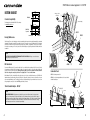
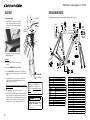
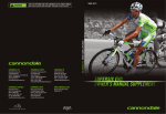
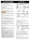
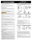
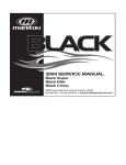
SyNAPSE Hi-Mod/CARBON.
(PATENT PENDING)
OWNER’S MANUAL SUPPLEMENT.
SYNAPSE Owner´s manual supplement - 129387.PDF
SAFETY INFORMATION
Important Composites Message
About This Supplement
Cannondale Owner’s Manual Supplements provide
important model specific safety, maintenance, and
technical information. They are not replacements for
your Cannondale Bicycle Owner’s Manual.
This supplement may be one of several for your bike.
Be sure to obtain and read all of them.
In this supplement, particularly important information is presented in the following ways:
WARNING
NOTICE
TIP
Indicates a hazardous situation which, if not
avoided, could result in death or serious injury.
Indicates special precautions that must be
taken to avoid damage.
A TIP provides helpful information.
If you need a manual or supplement, or have a question
about your bike, please contact your Cannondale
Dealer immediately, or call us at one of the telephone
numbers listed on the back cover of this manual.
You can download Adobe Acrobat PDF versions of any
Cannondale Owner’s Manuals or Supplements from our
website: www.cannondale.com.
■ This manual is not a comprehensive safety or
service manual for your bike.
■ This manual does not include assembly
instructions for your bike.
■ All Cannondale bikes must be completely
assembled and inspected for proper operation by
a Cannondale Dealer before delivery to the owner.
WARNING
This supplement may include procedures beyond
the scope of general mechanical aptitude.
Special tools, skills, and knowledge may be
required. Improper mechanical work increases the
risk of an accident. Any bicycle accident has risk
of serious injury, paralysis or death. To minimize
risk we strongly recommend that owners always
have mechanical work done by an authorized
Cannondale retailer.
WARNING
Your bike (frame and components) is made from
composite materials also known as “carbon fiber.”
All riders must understand a fundamental reality
of composites. Composite materials constructed of
carbon fibers are strong and light, but when crashed or
overloaded, carbon fibers do not bend, they break.
For your safety, as you own and use the bike, you must
follow proper service, maintenance, and inspection of all
the composites (frame, stem, fork, handlebar, seat post,
etc.) Ask your Cannondale Dealer for help.
We urge you to read PART II, Section D. “Inspect For
Safety” in your Cannondale Bicycle Owner’s Manual
BEFORE you ride.
YOU CAN BE SEVERELY INJURED, PARALYZED OR KILLED
IN AN ACCIDENT IF YOU IGNORE THIS MESSAGE.
Intended Use
ASTM F2043
Suitable for
road riding
(only)
The intended use of all
models is ASTM CONDITION 1,
High-Performance Road.
WARNING
UNDERSTAND YOUR BIKE AND ITS INTENDED USE.
USING YOUR BIKE THE WRONG WAY IS DANGEROUS.
Please read your Cannondale Bicycle Owner’s
Manual for more information about Intended Use
and Conditions 1-5.
This manual meets EN standards
14764, 14766, and 14781.
Vélo certifié conforme aux exigences du décret
N 95-937 du 24 août 1995 norme NFR030
129387 (04/13)
1
SYNAPSE Owner´s manual supplement - 129387.PDF
Inspection & Crash Damage Of
Carbon Frames/Forks
WARNING
Inspect frame carefully for damage (See PART II, Section
D. Inspect For Safety in your Cannondale Bicycle Owner’s
Manual. )
Do not ride your bike if you see any sign of damage, such
as broken, splintered, or delaminated carbon fiber.
■
■
■
■
MAY
INDICATE
A
An unusual or strange feel to the frame
Carbon which has a soft feel or altered shape
Creaking or other unexplained noises,
Visible cracks, a white or milky color present in
carbon fiber section
Continuing to ride a damaged frame increases the
chances of frame failure, with the possibility of injury
or death of the rider.
Repainting Or Refinishing
WARNING
Repainting, painting over, retouching, or refinishing
your frame or fork can result in severe damage
leading to an accident. You can be severely injured,
paralyzed or killed.
Refinishing chemicals : Solvents, and strippers can
attack, weaken, or destroy the important composite
chemical bonds holding your frame together.
Using abrasives or sanding the frame/fork
structure, original paint, decals, or coatings
through the use of mechanical actions such as
plastic or glass bead blasting or other abrasive
methods such as sanding or scraping can remove
frame material or weaken it.
2
Trainers
Water Bottles
The clamping jaws of a bike stand can generate a
crushing force strong enough to seriously damage your
frame.
If you ride a trainer that requires removal of the front
wheel and clamps the fork dropouts: Be sure your fork
quick release is tight! Relative movement will wear
parts, weaken and damage your bike.
Side impacts to a water bottle or cage can result in
damage threaded inserts due to the leverage on a
very small area. In a crash, certainly the last thing
you should be worried about is saving the threaded
inserts in your frame. However, when you are storing or
transporting your bike, take steps to prevent situations
where a water bottle may be hit or bumped by a strong
force that would cause damage. Remove bottle and
cage when you are packing your bike for travel.
NOTICE
AFTER A CRASH OR IMPACT:
ANY OF THE FOLLOWING
DELAMINATION OR DAMAGE:
Bicycle Repair / Work Stands
Never place your bike in a bike stand by clamping the
frame.
Place your bike in a stand by extending the seat post and
positioning the stand clamp on the extended seat post.
Don’t extend beyond the MINIMUM INSERT line marked on
the seat post.
Since your carbon seat post can also be damaged by
clamping force, adjust the stand clamp for the minimum
clamping force needed to secure the bike.
Also, before clamping, clean the post and protect the seat
post finish with a rag.
If you have an old un-used seat post, use it instead of
your regular post to mount your bike in a stand.
Tightening Torques
Correct tightening torque for the fasteners (bolts, screws,
nuts) on your bicycle is very important to your safety. Correct
tightening torque for the fasteners is also important for the
durability and performance of your bicycle. We urge you to
have your Dealer correctly torque all fasteners using a torque
wrench. If you decide to torque fasteners yourself always use
a torque wrench.
Find Tightening Torque Information
The wide range of bicycle models and components used means
that a listing of tightening torque would be out of date by the
time it was published. Many fasteners should be installed with
a thread locking adhesive such as Loctite®.
To determine correct tightening torque and any adhesive
application for a fastener we ask you to check:
• Markings on the component. Many components are
marked. On-product marking is becoming common.
•
Torque specs in the component
instructions shipped with your bicycle.
manufacturers
•
Torque specs listed on the websites of component
manufacturers.
•
With your Dealer. Dealers have access to current data and
have experience with correct torque for most fasteners.
If you ride a trainer that holds the bike up by clamping
the rear quick release between two cones: Take off the
nice, lightweight quick release that came with your
bike. Substitute a heavy, classic all steel quick release
and clamp it tight! Relative movement will wear parts,
weaken and damage your bike. Note that many modern
quick releases will not fit the clamping cones in this
kind of trainer because their shapes are incompatible.
If you ride a trainer a lot, consider using an old bike:
Corrosion from sweat will take it’s toll. Weight is
irrelevant. Save wear on your expensive components.
Periodically check the attachment of the bottle cage;
tighten the cage bolts if necessary. Don’t ride with a
loose bottle cage. Riding with loose cage bolts can
produce a rocking motion or vibration of the attached
cage. A loose cage will damage the insert and possibly
lead to the inserts to pull out. It may be possible to
repair a loose insert, or install another insert only if the
frame is undamaged. Replacement requires the use
of a special tool. If you notice damage to the threaded
insert, please ask your Cannondale Dealer for help.
Ask you dealer for help with trainers, the right one and
the correct way to use it.
Building Up A Frameset
Be particularly cautious with a carbon frame or fork.
Carbon is relatively soft, not abrasion resistant. If there
is any relative movement, carbon will wear quickly.
NOTICE
TRAINERS - Improperly mounting a bike in a trainer,
or using one that is not compatible with your
particular bike frame can cause serious damage.
WATER BOTTLES - An impact, crash, or loose bottle
cage can result in damage to your frame.
This kind of damage is not covered by the
Cannondale Limited Warranty.
Before building up a frameset, consult with your
Cannondale Dealer and the component manufacturers,
and discuss your riding style, ability, weight, and
interest in and patience for maintenance.
Make sure the components chosen are compatible with
your bike and intended for your weight and riding style.
Generally speaking, lighter weight components have
shorter lives. In selecting lightweight components, you
are making a trade-off, favoring the higher performance
that comes with less weight over longevity. If you
choose more lightweight components, you must inspect
them more frequently. If you are a heavier rider or have
a rough, abusive or “go for it” riding style, buy heavy
duty components.
Read and follow the component manufacturers
warnings and instructions.
3
SYNAPSE Owner´s manual supplement - 129387.PDF
bottom bracket
Crankset Compatibility
68mm
34mm
34mm
Shimano Code No.
Y7ET98030
BB30-68
6.
(c)
KF103/
The bottom bracket shell width is BB30-73A cranksets.
See www.BB30standard.com
(Patent Pending)
(5mm) 73mm
39mm
34mm
BB30-73A
Asymmetric
Bearing Maintenance
Non-Drive Side
Drive Side
Shell bearings (1) are sealed cartridge type and do not require lubrication. Inspect bearing condition annually (at a minimum)
and anytime the crankset assembly is disassembled or serviced. The bearings are a press fit within the shell. Old bearings
should not be reinstalled if removed. Replace both bearings at the same time. Replacements circlips (2) are available if
the circlips become damaged. The circlips can be lifted from the BB groove (a) by lifting the hooked end with a thin blade
screwdriver.
(a)
(f)
DO NOT FACE, MILL OR MACHINE THE BOTTOM BRACKET SHELL FOR ANY REASON. Doing so can result in serious
damage and possibly a ruined bike frame.
3.
(b)
4.
BB Cable Guide
When Shimano Di2 cables are installed the cable guide is not used. In its place, install the alternate cover (5). The BB shell
internal windows (e) enable routing of the various Di2 cables. When cables are routed, be sure to position them so they are
not in contact with crankset parts. The exit hole (c) will accept the Shimano fitting; it is open when not in use. You can cover
this opening with a small piece of the clear KF103/ guard material, if desired.
KP018/
2.
(g)
NOTICE
To remove the BB cable guide (3), remove the cables first. Use a small thin blade screwdriver to lift off the cover (4). Insert
the screwdriver into the guide slot (b) and turn it clockwise – this retracts the claws (f) of the cable guide and allows the
guide to be removed. from the shell slot (g) . When replacing the guide cover, be sure to align the cover tabs (d) with the
slots in the cable guide correctly; they are offset. The opening of the “C” faces the left crankarm.
QC616/
1.
(e)
5.
KP299/
KP298/
(d)
Cannondale Tools
KT011/ is a bearing removal tool.
KT010/ is a set of bearing installation tools to be used with a
standard headset press.
73mm Standard Adapter - KF368/
KT011/
Loctite 609
groove
NOTICE
SERIOUS FRAME DAMAGE - All Adapters must be installed by a professional bike mechanic. No adapter should
be used as a frame repair part. Adapters should only be used in undamaged frames in good condition. Improper
installation or removal can result in damage and void applicable frame warranty. The adapter is removable, however,
repeated removal and reinstallation could result in damage to the SI BB shell and is not recommended. Damage
caused by improper removal is not covered under your warranty.
KF368/
4
KT010/
5
SYNAPSE Owner´s manual supplement - 129387.PDF
SERIAL NUMBER
1
The serial number located on the bottom
bracket. It is a 7-character barcode (1). Use
this serial number to registration your bike. See
your Cannondale Bicycle Owner’s Manual for
more information on warranty registration.
The chainstay plate KP304/ located on the right
chainstay just behind the chain rings, protects
the chainstay from damage in the event the
chain is dropped from the chain ring. Contact
your Cannondale Dealer for a replacement if it
becomes missing or damaged.
www.cannondale.com/registerbike/
Other codes (2) on the BB shell are related to
production including model year , frame type,
frame size, and color coding. The same product
code may appear on many bikes and does not
uniquely identify your frame.
CHAINSTAY PROTECTION
KP
30
4/
2
REAR DERAILLEUR HANGER
CLEAR FILM
To replace:
Remove the mounting screws and remove the old
hanger from the dropout. Clean the area around
the dropout and inspect the frame carefully for
any cracks or damage. If you find damage have
the frame inspected by your Cannondale Dealer .
If the dropout is un-damaged, apply a light film
of bike grease to both sides of the dropout. This
will help minimize any noise or “creaking” that
might result from very slight movement between
the dropout and hanger during movement of the
derailleur.
Slide the new hanger KP158/ onto the dropout.
Apply Loctite to the screw threads and tighten to
the specified torque.
NOTICE
Do not use a derailleur hanger alignment
tool. If bending adjustment is necessary,
remove the hanger from the frame first!
6
The clear adhesive film protector applied to
the top surface of the right chainstay provides
limited protection against frame or finish
damage caused by the chain. Replacements
are available through a Cannondale Dealer.
DROPOUT
KP158/
RD HANGER
1.1 Nm, 10 InLbs
Loctite 242 (blue)
7
SYNAPSE Owner´s manual supplement - 129387.PDF
SI Compression Assembly KP017/ Instructions
INSTALLED CORRECTLY
48 mm
Do not grease.
KP017/
REV. 1
6Nm, 53InLbs
KP224/
Expander at
lower stem bolt
2 - 3 mm
STEERER TUBE
Top cap at
upper stem bolt
CABLE ROUTING
KP063/
STEM
55mm
HEADSET SPACERS
HEADSET TOP CAP
Di2
EXPLODED VIEW
HEADTUBE
MAXIMUM STACK HEIGHT
Measure from the top edge of the
headtube to the bottom edge
of the stem.
REV. 1
4Nm, 35InLbs
TOP CAP
EXPANDER BOLT
KP302/
EXPANDER
Di2
KP298/
The following procedure should only be completed by a professional bike mechanic.
1. Assemble the fork, headset, spacers, and stem without tightening the stem bolts onto the head tube. When
the system is assembled, the carbon steerer tube should be 2-3 mm below the top of the stem. All spacers
must be located below the stem and within the maximum stack height as shown. No spacers may be used above
the stem.
2. Set-up the compression assembly before inserting it. Adjust the length so that the expander is located at
lower stem bolt. The top cap and the expander end provides critical support to the carbon steerer when
tightening the stem bolts. Adjust the length by threading the top cap on the expander parts.
3. When the assembly is the correct length, insert it into the steerer tube. It is designed to fit snugly inside the
steerer. Insert an Allen key through the access hole in the TOP CAP and into the EXPANDER BOLT. Tighten the
to the specified torque.
Di2
The top tube guide KP063/ is removable so that brake cable may be routed inside the tube. The guide is
secured in the tube opening by the installed brake cable tension. Make sure the guide is seated properly
in the top tube opening when installing and connecting the rear brake.
Be sure to use ferrules on DT housing ends.
When using Shimano Di2, the DT openings are fitted with rubber seals included in KP298/. Notice the
small opening below the rear brake headtube inlet. This is for Di2 cabling. The rear derailleur exit is also
included in the Di2 kit .
4. Now, to set bearing preload, insert a 6mm allen key into the hex shape in the TOP CAP itself. Turn the entire
top cap clockwise to increase preload. Turning it counter-clockwise will decrease the preload. When the
headset preload feels correct, turn the stem to align the handlebar and tighten the stem fork clamp bolts
to the torque specified for the stem. Consult the stem manufacturer’s instructions. The torque values for
components are often marked on the part.
8
9
SYNAPSE Owner´s manual supplement - 129387.PDF
SEAT POST
REPLACEMENT PARTS
To adjust saddle height:
25.4 mm - SEAT POST
1.Insert 4mm Allen key through cover (1) into binder
bolt (2). Turn counter clockwise to loosen clamp.
Hold cover in place while turning or removing the
allen key.
4 mm
The following replacement part kits are available through a Cannondale Dealer:
KP269/
KP300/
5-6 Nm,
44-53 InLbs
KF115/
CARBON GEL
KP203/
KP301/
KP063/
KP017/
optional
HEadset
Spacer light
KP224/
1.
2.
3.
30mm
A
C4FLHS30BLK
C4FLHS30WT
C4FLHS30BZ
4.
(a)
KF103/
5.
A
Shimano Code No.
Y7ET98030
KP157/
2. Set saddle hieght and tighten the binder bolt to
5-6Nm, 44- 53 In Lbs.
12.5mm
KP302/
KP158/
Please Note:
KP010/
■ The seatpost size is 25.4mm. Do not use adapters
or shims.
KP304/
■ The seatpost MINIMUM INSERT depth is 100mm.
KB6180/
KP018/
■ The frame INSERT LIMIT varies with frame size. Do not allow an
installed seatpost to touch the water bottle boss. This will result in
damage.
■ Periodically, remove the seat post and grease the bolt threads,
washer (3) and wedge faces with standard bike grease (avoid
applying carbon gel to these areas).
Apply carbon gel inside the seat tube and on the seat post before
inserting the seatpost.
■ If the removable cover (1) comes out, press it back in.
■ The center wedge (a) cannot be removed. The upper (3) and lower
wedge could drop into the seat tube, if the bolt (2) is un-threaded
completely. Invert the seat tube and allow them to drop out if this
happens. Unless you are removing the clamp assembly parts to
clean them, there is no need to completely un-thread the bolt.
10
QC616/
A
KP299/
INSERT LIMIT
Water Bottle Boss
For more information about carbon fiber
seat posts, see also “APPENDIX D. Care
and Maintenance of Carbon Fiber Seat
Posts” in your Cannondale Bicycle Owner’s
Manual.
WARNING
THE SEAT POST MUST ONLY BE CUT BY A
PROFESSIONAL BIKE MECHANIC. Incorrectly
cutting the seat post can result in damage
leading to an accident.
Fork
KP017/
KP203/
KP157/
KIT COMP ASSY 23 6ID EXPANDER
KIT HEADSET NEW SYNAPSE CRB / SUPERSIX EVO CRB
KIT BRAKE BOLT 12 5MM
Frame parts
KP158/
KP224/
KIT DER HANGER RD CAAD10
KIT GUIDE BRAKE H-TUBE SUPERSIX EVO
A
KP298/
KIT DI2 SYNAPSE PLUGS BB COVER
KP299/
KP302/
KIT SYNAPSE BB CABLE GUIDE MECH.
KIT DROPOUT CABLE STOP (20X)
Frame accessories
KIT GUARD SCUFFGUARD 8PK
KF103/
KIT CH STAY PROTECT SYNAPSE
KF367/
KIT QR SKEWER TRAINER 130MM
KA048/
Seatpost Assembly
KP300/
KIT SYNAPSE SEATPOST WEDGE ASSEMBLY
KP301/
KIT SYNAPSE WEDGE COVER (10X)
KF115/
KIT GEL DYNAMIC CARBN SEATPOST
Seatpost
C703011110
C703011010
C703011111
C703011011
SEATPOST C2 25.4X350 15 BQ
SEATPOST C2 25.4X350 00 BQ
SEATPOST C3 25.4X350 15 BQ
SEATPOST C3 25.4X350 00 BQ
Bottom Bracket
KB6180/
KIT BEARING BB SI 2PCS
KP018/
KIT BEARING BB SI CERAMIC 2PCS
QC616/
KIT CIRCLIPS (2) BB SI
KP010/
KIT ADAPTER SIBB TO 73MM TAP
KP250/
KIT SPINDLE-SL2 ROAD 109
Tools
KF368/
KF366/
KIT TOOL SIBB/73 ADP INSTALL
KIT TOOL SI BB ADAPTER EXTRACT
11
SYNAPSE Owner´s manual supplement - 129387.PDF
GEOMETRY & SPECIFICATIONS
A
0
M
N
B
D
C
F
E
L
K G
H
I
WOMEN’S
Sizes (cm)
A
B
C
D
E
F
G
H
I
J
K
L
M
N
O
Horizontal Top Tube Length (cm)
Measured Size (cm)*
Seat Tube Angle (degrees)
Head Tube Angle (degrees)
Chain Stay Length (cm)
Fork Rake (Cm)
Bottom Bracket Height (cm)
Wheelbase (cm)
Trail (cm)
Standover at Top Tube Midpoint (cm)
Bottom Bracket Drop (cm)
Front Center Distance (cm)
Head Tube Length (cm)
Stack (cm)**
Reach (cm)
Intended Use
Bottom Bracket
Headset
Headset Compression Assembly
Seatpost
Seat Binder
Rear Derailleur Hanger
Dropout Spacing
Front Derailleur
Maximum Weight Limit
44
48
51
MEN’s
54
56
48
51
54
56
49.0 50.5 52.0 53.5 55.0 51
52.5 54.2 56
38
40.5 43
46
49
43
46
49
51
75.3 ° 74.9 ° 74.5 ° 74.1 ° 73.7 ° 74.6 ° 74.3 ° 73.9 ° 73.5 °
69.7 ° 70.6 ° 71.3 ° 72.0 ° 72.7 ° 70.8 ° 71.3 ° 72.0 ° 72.5 °
41
41
41
41
41
41
41
41
41
5.5
5.5
5.5
5.0
5.0
5
5
4.5
4.5
26.5 26.5 26.5 26.7 26.7 26.5 26.5 26.7 26.7
98.1 98.5 99.0 99.1 99.5 97.6 98.6 99.0 100.0
6.7
6.1
5.7
5.8
5.4
6.6
6.2
6.3
6.0
70.0 72.9 75.0 77.8 79.8 72.7 75.1 78.3 80.2
7.5
7.5
7.5
7.3
7.3
7.5
7.5
7.3
7.3
57.8 58.2 58.7 58.7 59.2 57.3 58.3 58.7 59.6
12.0 13.5 15.0 16.5 18.0 12.5 14.5 16.5 18.5
51.6 53.3 55.0 56.7 58.4 52.9 54.9 57.0 59.0
35.6 36.2 36.8 37.4 38.0 36.2 37.0 37.8 38.6
ASTM Condition 1, High-Performance Road
BB30, 73A mm w/Adapter
(upper 1 1/8 Campy, Hiddenset, lower 1 1/4 Cannondale) - KP203/
Cannondale SI - KP017/
25.4 mm
Cannondale - KF300/, 5-6.0 Nm, 44-53.0 In Lbs
Cannondale - KP158/
Front 100 mm, Rear 130 mm
Bolt On
Rider (275lbs/125kg), Luggage1 (10lbs/4.5kg), Total(285/129kg)
58
61
58
54
73.0 °
73.0 °
41.3
4.5
27.0
101.3
5.7
82.4
7.0
60.6
20.7
61.1
39.4
60
57.5
72.5 °
73.5 °
41.3
4.5
27.0
102.8
5.7
85.0
7.0
62.0
23.0
63.1
40.2
* The measured size is from the center of the bottom bracket to the top of the top tube, measured along the seat tube axis. All sizes have a slightly sloping top tube.
** Stack is measured vertically from the center of the BB to the top of the head tube, reach is measured horizontally from the center of the BB to the top of the head tube.
1. Seat Bag /Handlebar Bag Only
12
13
WARNING! READ THIS SUPPLEMENT AND YOUR CANNONDALE BICYCLE
OWNER’S MANUAL. Both contain important safety information.
Keep both for future reference.
CANNONDALE USA
CANNONDALE EUROPE
CANNONDALE UK
Cycling Sports Group, Inc.
172 Friendship Road,
Bedford, Pennsylvania, 15522-6600, USA
(Voice): 1-800-BIKE-USA
(Fax): 814-623-6173
[email protected]
Cycling Sports Group Europe, B.V.
mail: Postbus 5100
visits: Hanzepoort 27
7570 GC, Oldenzaal, Netherlands
(Voice): +41 61.4879380
(Fax): 31-5415-14240
[email protected]
Cycling Sports Group
Vantage Way, The Fulcrum,
Poole, Dorset, BH12 4NU
(Voice): +44 (0)1202 732288
(Fax): +44 (0)1202 723366
[email protected]
CANNONDALE AUSTRALIA
CANNONDALE JAPAN
www.cannondale.com
Cycling Sports Group
Unit 8, 31-41 Bridge Road
Stanmore NSW 2048
Phone: +61 (0)2 8595 4444
Fax: +61 (0) 8595 4499
[email protected]
Namba Sumiso Building 9F,
4-19, Minami Horie 1-chome,
Nishi-ku, Osaka 550-0015, Japan
(Voice): 06-6110-9390
(Fax): 06-6110-9361
[email protected]
© 2013 Cycling Sports Group
129387 (04/13)