1
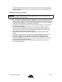
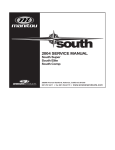
2004 SERVICE MANUAL
Skareb Platinum
Skareb Super
Skareb Elite
Skareb Comp
28209 Avenue Stanford, Valencia, California 91355
661 257-4411 | fax 661 294-4179 |
www.answerproducts.com
Table of Contents
Description
Page
Introduction
3
Glossary of Terms
4
Disassembly Instructions
8
Assembly Instructions
10
Bushing Removal and Installation Instructions
14
Troubleshooting Chart
18
Skareb Comp & Elite Schematic and Torque Specifications
20
Skareb Super Schematic and Torque Specifications
21
Skareb Platinum Schematic and Torque Specifications
22
Skareb Service Kit Chart
23
Contact Information
Answer Products Customer Service Department
28209 Ave. Stanford
Valencia, CA 91355
Toll Free: (800) 423-0273
Direct: (661) 257-4411
FAX:
(661) 775-1798
E-mail: [email protected]
[email protected]
Web site: www.answerproducts.com
04 SKAREB SERVICE MANUAL
Page 2
REV NC
INTRODUCTION
This manual is intended to guide the user through basic service of Manitou Skareb front forks.
Service is supported by the identification of common parts and assemblies that have been
assembled into Service Kits. The purpose of this manual will be to describe conditions that may
drive the need for service and to provide installation instructions for the kits.
Due to the time-consuming nature suspension fork service, at this time our primary focus is to
offer service kits that minimize the amount of downtime and labor involved.
Important information is highlighted in this manual by the following notations:
WARNING
Failure to follow WARNING instructions could result in severe injury or death to the
person inspecting or repairing the suspension fork or the user.
CAUTION
A CAUTION a caution indicates special precautions that must be taken to avoid damage to
the product.
NOTE
A NOTE provides key information to make procedures easier or clearer
GENERAL WARNING: Suspension forks by design contain gases and fluids under extreme
pressure and warnings contained in this manual must be observed to reduce the
possibility of injury or possible death. Following these instructions can help you reduce
the risk of being injured. Any questions in regards to the information in this manual
should be directed to Answer Products Customer Service at (661) 257-4411.
WARNING Suspension forks use compressed air to provide fluid pressure in the damping
system and spring resistance in Air models. BOTH systems must be relieved of pressure
prior to servicing these systems. Failure to relieve air pressure could result in injury or
possible death.
CAUTION: The Skareb suspension fork uses precision machined aluminum and other soft
alloy components. Using correct tools for assembly is essential to prevent damage.
04 SKAREB SERVICE MANUAL
Page 3
REV NC
GLOSSARY OF TERMS
Air Cap – Top cap that threads into top of air/spring leg (this is the left leg of the fork as you are
seated on the seat). Forks may be controlled with an air/spring or a coil spring. The air cap
contains the Schrader Valve, which is used to control the spring rate or SAG of air forks.
Air Spring – A mechanism that is used to control the SAG of an air fork.
Arch – A support that connects the two outer lower legs of the casting so as to keep them moving
in unison.
Boss – The word used to describe an outer casting that has brake posts for V-brakes or
cantilever brakes.
Bottom Out Bumper – A rubber or elastomer device that absorbs the shock that occurs when a
suspension is compression to its limit.
Bushings – A cylindrical sleeve between a fork stanchion tube (inner leg) and a fork outer
casting (slider), which facilitates the sliding movement between these two parts.
Coil Spring – A coiled piece of metal that acts as a spring to help suspend a fork.
Compression – The phase of the suspension operation in which the wheel travels up, or travels
closer to the frame. The suspension forks reaction to a bump in the trail.
Compression Damping – Restriction of the rate that the suspension compresses under load.
Crown Steerer Assembly – the stanchion legs (inner legs), the fork crown, and the steer tube
pressed together as one assembly. This assembly is then finished by adding all of the fork
internals and then outer casting (slider).
Damping – A function that modifies the rate of suspension compression or rebound.
Detent – An indentation that causes a rotating adjuster to stop at fixed increments.
Drop Out – The end of an outer casting (slider) where the wheel attaches.
FFD – Fluid Flow Damping. A Manitou patented low cost oil damping system. The compression
damping is non-adjustable and the rebound damping may be non-adjustable or adjustable
damping.
04 SKAREB SERVICE MANUAL
Page 4
REV NC
GLOSSARY OF TERMS (CONT.)
Fork Crown – The component that joins the stanchion tubes (inner legs) to the steer tube of the
fork.
Hydraulic Fork Oil – Oil used in suspension designs to provide damping. It has special
characteristics that determine how it reacts when exposed to compressed air, how it changes
viscosity when its temperature changes, and how it moves through valves.
Hydraulic Lock Out – a condition caused when the mixture of air and damping oil is out of
balance. It is caused when there is too little air space in a chamber, not allowing the fork to
compress through its travel.
Lock Out – a special function that restricts the compression of the fork from moving. It is
generally controlled by an external knob that is activated when a rider does not want the fork to
move, thus eliminating extra energy needed to overcome the bobbing forces of the fork.
MCU – (Micro-Cellular Urethane) Special urethane that is filled with tiny air cells that act like
springs when the elastomer is compressed.
No Boss - The word used to describe an outer casting that has no brake posts for V-brakes or
cantilever brakes. This casting is to be used for disk brakes only.
Oil Damping – A system that uses the resistance to oil flow through holes in a valve to provide a
means to alter the rate of suspension compression or rebound.
Oil Level – The level of damping oil needed for the optimal damping performance of a
suspension. It is measured as the air space distance between the top of the stanchion leg (inner
leg) and the height of the oil inside of the leg. The fork must be completely extended in order to
get an accurate measurement.
O-Ring – A soft, flexible neoprene or Buna rubber ring with a round cross-section, which is used
for sealing and retention.
Oil Weight – A description of the relative viscosity of oil, such as hydraulic oil. Oil with low weight
numbers (5wt or 7wt) flow through valves with less resistance than higher weight numbers (10or
15 wt).
Outer Casting – (see Slider)
Preload – A condition of compressing a spring or elastomer before the operating loads are put on
the suspension, so that it provides a stiffer spring rate.
Piston – In front suspension, the part of the damper that slides back and forth inside of the
damping leg that houses the valves. It can also refer to the air piston in the air/spring assembly
that slides back and forth compressing the air, thus causing a change in the spring rate of the
suspension.
04 SKAREB SERVICE MANUAL
Page 5
REV NC
GLOSSARY OF TERMS (CONT.)
Porosity – The condition or property of having pores in a material that will allow gas or liquid to
pass through it.
Rebound – The phase of the suspension operation in which the wheel returns to its original
position on the ground after compression.
Rebound Damping – Restriction of the rate that the suspension rebounds when the compression
load is relived.
Reverse Arch Technology – Also known as RA. It is a system that is designed to move the arch
of a fork to the backside of a fork, rather than the conventional front position. It was designed to
provide greater rotational torque strength to an outer casting (slider), without adding additional
weight to the fork.
SAG – The amount a suspension fork compresses at rest with a normal load (rider’s weight).
Schrader Valve – Valve used to introduce air into a chamber.
Seal – A part, usually neoprene rubber or Buna, that keeps contaminants out and/or working
fluids in.
Semi Bath – A lubrication system that uses a lubricating oil to keep the bushing surface and
stanchion legs (inner legs) as friction free as possible during movement of the stanchion legs.
Spring Rate – The rate at which the resistance of a spring increases as it is compressed.
SPV – (Stable Platform Valve) new damping system that allows the rider to set the pedaling
platform that he desires to pedal most efficiently in all situations. It is dependent on the pressure
that the SPV valve experiences from the movement of the wheel vs. the terrain and the platform
that is set by pressure introduced to other side of the SPV valve through changes of air pressure
working on the damping oil.
Slider/Outer Casting – The tube (outer casting leg) of the suspension fork that remains fixed to
the wheel. It slides up and down on the stanchion leg (inner leg).
Stanchion Clamps - (Double-Triple Clamps) the portions of the fork crown that clamp around the
stanchion legs above and below the head tube of the bicycle frame on specific long travel
applications.
Stanchion Legs – The suspension tube (inner leg) fixed to the fork crown. It remains stationary
during the operation of the suspension.
Steer Tube – The long cylindrical tube that extends from the top of the fork crown. Its function is
to be inserted into the bicycle head tube and attach the suspension to the bicycle frame.
04 SKAREB SERVICE MANUAL
Page 6
REV NC
GLOSSARY OF TERMS (CONT.)
Top Out Bumper – A rubber, coil spring, or elastomer device that absorbs the shock that occurs
when the load is taken off a suspension so that it is allowed to rebound to its limits
TPC – (Twin Piston Chamber) a patented damping system that has independent pistons for
rebound and compression. The system utilizes a mixture of air and oil in the damping leg of the
fork to enhance the damping performance.
Travel – The amount that a wheel moves between the most compressed and the most extended
states of the suspension
Viscosity – A description of how a liquid flows. Liquids with higher viscosity are thicker flow less
easily or quickly than liquids with low viscosity. This has an affect on the damping speeds of
rebound and compression.
Volume Control – A new system designed to work with SPV as a control of the compression
ramp up rate of the fork. It has a range of adjustments from linear to very progressive.
Wiper Seal – A rubber material that is used as a seal to keep dirt and water out of the outer
casting legs. It is not designed to keep air pressure or extreme oil pressure in. Manitou has the
new Evil Genius wiper seals.
04 SKAREB SERVICE MANUAL
Page 7
REV NC
2004 Skareb Forks Disassembly and Rebuild Instructions
Disassembly Instructions
Removal of Outer Casting
1. From the left leg dropout (Left when sitting on the bike), use a 4mm hex wrench to
remove the compression rod screw.
2. From the right leg dropout, if the fork has adjustable rebound, the knob will need to be
removed. Remove the 2mm hex screw inside the knob and remove the knob.
3. Use a 8mm hex wrench to turn the damper clockwise until it can be pushed into the
casting.
4. Remove crown/steer/inner leg assembly from the outer leg casting.
5. Position the bottom of the fork legs over a drain pan that is on the ground. Pull the
casting downward towards the pan, allowing the Semi Bath oil in the casting to drip into
the pan. Pull the casting completely off of the inner legs and wipe any excess oil off of
inner legs and inside of casting.
Bushing Removal & Installation
Please refer to section on Bushing Removal & Installation.
Removal of Compression Damping Assembly
Forks with FFD (non-adjustable) Damping
1. Remove top leg cap (FFD Assy) on right hand side using 27mm socket.
2. Pour old oil out of the top of the fork, then compress fork upside down over oil drain pan
3-5 times to get oil out from under rebound piston and discard appropriately.
Forks with Adjustable Compression/Lockout Damping
1.
2.
3.
4.
Remove the 2mm fixing screw on top of the damper knob on top right side of the fork.
Remove 2 balls and springs from inside the top cap.
Unscrew the compression damping assembly using a 24mm socket.
Pour old oil out of the top of the fork, then compress fork upside down over oil drain pan
3-5 times to get oil out from under rebound piston and discard appropriately.
Removal of SPV Compression Damping Assembly
WARNING This fork uses compressed air as part of the SPV damping system and must be
relieved of pressure prior to servicing. Failure to relieve air pressure could result in injury
or possible death.
1. If your fork has a red Schrader cap on the top right side of the fork, it is equipped with SPV
damping. Remove Schrader valve dust cap from Red Hex Shaped Top Cap on the top right
of the crown. Release all air pressure from the Schrader valve.
2. Remove SPV Volume Control Cap (Red Hex Shaped Top Cap) from top right of the crown
with a 24mm Socket. Turn fork upside down over drainage pan to empty Damping oil from
the inner leg. Stroke the Damper shaft on the bottom of the inner leg 3-5 times to purge the
leg of oil that is caught below the oil piston.
04 SKAREB SERVICE MANUAL
Page 8
REV NC
Removal of Rebound Damping Assembly
1. Unscrew Damper end cap from the bottom of the right leg and then pull out the rebound
damper.
Removal of SPV Rebound Damping Assembly
1. If your fork had a red Schrader cap on the top right side of the fork when removing the
compression damper above, it is equipped with SPV damping and will have the companion
SPV rebound assembly. Unscrew damper end cap from the bottom of the right leg using a
24mm Open-end wrench or 8-10” Adjustable wrench and then pull out the SPV rebound
assembly.
2. Checking the function of the SPV valve - Visually inspect the gap between the SPV valve and
the bottom of the damping piston. It should have approximately 1mm of space. The valve
should also spring back to its open rested position after compressing it with your fingers. If
the valve is not responsive or all the time closed, it is bad and the rebound assembly needs
to be replaced.
Check for 1mm gap
between the blue
SPV valve and the
black piston
Removal of Air Piston and Compression Rod Assembly
There are now two ways to remove the air piston from the inner leg.
1. An Air Piston Removal tool has been developed that will enable you to remove the piston
without having to take the fork apart. (P/N: 85-8062).
2. Without this new tool, you will need to follow the procedures in the following section.
WARNING This fork uses compressed air to provide spring resistance and must be
relieved of pressure prior to servicing. Failure to relieve air pressure could result in injury
or possible death.
1. Remove air dust cap covering the Schrader valves.
a. Depress Schrader valve to release air pressure.
b. Remove air cap on top of Left leg with 20mm socket.
2. Remove rebound adjuster knob using a 2mm hex wrench.
04 SKAREB SERVICE MANUAL
Page 9
REV NC
3. From the right leg dropout, use 8mm hex wrench to turn the damper shaft clockwise until
it can be pushed into the casting.
4. Remove 11mm hex bolt (Compression Rod bolt) from bottom of Left leg.
5. Remove crown/steer/inner leg assembly from the outer leg casting over a drain pan,
because Semi Bath oil will leak out of bottom of casting once you pull the inner legs from
the outer casting legs.
6. Be sure to drain all Semi Bath oil out of casting before re-assembly of fork.
7. Remove left leg end cap and compression rod assembly from inner left leg. Then remove
spring and Air piston rod.
8. Use a long narrow rod approximately 18”/458mm long and no greater than _”/7mm in
diameter and insert it into the left inner leg from the bottom of the leg. Be sure to direct
the rod through the center of the negative spring assembly that is about halfway up the
inner leg. Once the rod has contacted the air piston, use a rubber mallet and tap the
piston out through the top of the inner leg.
Tapping Piston out
with long rod
Assembly Instructions
Assembly of Air Piston and Compression Rod Assembly
WARNING All leg caps for Damper and Spring systems must be properly tightened prior to
use. Failure to do so could result in injury or possible death.
1. Apply a small amount of Prep M grease onto the threads at the top of the left inner leg
with your finger.
2. Apply a small amount of Prep M grease around the outside diameter of the new air
piston.
3. Insert the air piston (metal side up) into the inner leg through the threaded area at the top
of the inner leg. Use your fingers to push the piston past the threads into the leg.
Air Piston is
inserted into
inner leg with
metal side
facing up
04 SKAREB SERVICE MANUAL
Page 10
REV NC
4. Re-install the air push rod, positive spring (that has been well greased), and compression
rod assembly. Tighten per the Fastener and Torque Values section.
5. Pour about 3cc of a 40wt or greater automotive oil into the top of the piston and then
install the air cap assembly. Tighten the air cap assembly 30-50in/lbs.
Make sure to apply a thin layer of
grease to inner threads and outside of
piston before installation.
Pour 3 cc of oil into top of piston
6. Fully extend the damper shaft and slide the rubber bumper against the inner leg end cap.
Insert the crown/steer assembly into the outer legs to the upper bushing. Holding the fork
horizontal, inject 16cc of 5-40wt Semi bath oil into the hole at the bottom of each outer
leg (Figure 2). A syringe works well for this procedure.
7. Push the outer legs past the lower bushing and reinstall the 4mm bolt and tighten 8mm
damper fitting in a counterclockwise direction. Tighten per the Fastener and Torque
Values section.
8. Use a shock pump (p/n 85-4069) to fill the air system to the recommended levels as
outlined in the Fastener and Torque Values section.
Reassembly of Crown Steer/Leg Assembly
WARNING All top caps for Damper and Spring systems must be properly tightened prior to
use. Failure to do so could result in injury or possible death.
WARNING All leg caps for Damper and Spring systems must be properly tightened prior to
use. Failure to do so could result in injury or possible death.
1. Grease the outside of the air piston and then apply a thin film of grease to the threads at the
top of the inner leg. It is recommended to use Prep M grease (P/N: 85-0031). Push the piston
into the top of the left inner leg with the metallic side of the piston facing you, using your
thumb. Push the piston past the threads and then pour approximately 3-4cc’s of a 20-50wt oil
(P/N: 85-0022) into the top of the piston. This oil needs to be checked about every 6-8 weeks
of riding time. It will dissipate over time and then you may experience some air leakage and
increased stiction in the fork movement.
2. Install the air cap and tighten it to value given on fork schematic.
3. Turn crown/steer/leg assembly over, so that the bottoms of the inner legs are facing you. In
the same leg that you just installed the air piston and air cap into; insert the air push rod
(longer end in first), then the positive spring (this is your ride kit spring) onto the short end of
the push rod, then install the compression rod assembly, and tighten end cap into leg.
Tighten to torque values that are listed on fork schematic.
4. Now, install damping assembly into bottom of other inner leg. If your fork uses SPV damping,
be sure to check the function of the SPV valve and apply a thin layer of Prep M grease onto
04 SKAREB SERVICE MANUAL
Page 11
REV NC
o-ring that is around the piston at top of assembly. Install the assembly and tighten end cap
to specified torque value.
Assembly of Compression Damping Assembly - Non-Adjustable FFD
WARNING All top caps for Damper and Spring systems must be properly tightened prior to
use. Failure to do so could result in injury or possible death.
1. Put a little bit of Prep M grease (Ref Answer Products PN 85-0031) on o-ring found on
the lower piston of the FFD assembly.
2. Install the FFD Assy into the top right hand of the crown/steer using a 27mm socket.
Tighten per the Skareb Schematic and Torque Specification Table.
Assembly of Compression Damping Assembly - Adjustable Compression/Lockout
WARNING All top caps for Damper and Spring systems must be properly tightened prior to
use. Failure to do so could result in injury or possible death.
1. Fill right leg with damping oil using 5wt Motorex fork oil (Ref Answer Products PN 850023) to the height noted in the Skareb Schematic and Torque Specification Table. Cover
the opening at the top of the right leg of the crown/steer with a rag and cycle the fork six
times. Recheck oil level and add/drain to meet the level requirement.
2. Put a little bit of Prep M grease (Ref Answer Products PN 85-0031) on the urethane or
brown rubber o-ring found on the lower piston of the Lock out assembly.
3. Twist the Hex shaped aluminum shaft that sticks up from the top cap counter clockwise
until it stops (the system is completely open to oil flow at this point).
4. Using a motion like screwing in a screw. Twist the assy. and apply a little pressure to
insert the piston part of the mechanism past the threads at the top of the inner leg. Then
push the assy. into the leg until the threads on the cap intersect the threads inside the
inner leg, screw the cap. Tighten per the Skareb Schematic and Torque Specification
Table.
5. Once the cap is tightened, twist the Hex shaped shaft clockwise until it stops (this is the
locked out position). Insert the springs into opposite holes in the top cap and then place
the ball bearings on top of the springs (place a little dab of grease on spring to hold ball
bearing in place).
6. Place the adjuster knob onto the hex shaped aluminum shaft and seat it onto the top cap
and ball bearing. Position the adjuster cap so that the lever part of the cap is at the
farthest point to the back of the crown.
7. Insert 2mm fixing screw and tighten to secure the knob. Twist the knob counter clockwise
to activate the fork suspension. Compress the fork several times to circulate the oil
through the system and then activate the Lock out system by moving the lever clockwise
to its stopping point at the back of the crown. The fork should have approximately 5 mm
of progressive travel before it locks out.
Note: This system is a combination of adjustable compression damping that becomes a lock
out. It is fully active when the lever is facing all the way forward (counter clockwise) and
locked out when the lever is facing all the way towards the back of the crown (clockwise).
Assembly of Compression Damping Assembly - SPV
WARNING All top caps for Damper and Spring systems must be properly tightened prior to
use. Failure to do so could result in injury or possible death.
1. Insert the Volume control assembly into the top of the right inner leg and tighten per the
Skareb Schematic and Torque Specification Table. Be sure that you unscrew the red
04 SKAREB SERVICE MANUAL
Page 12
REV NC
16mm Hex shaped Volume control nut all of the way counterclockwise after you tighten
the entire assembly into the inner leg. Use: the Manitou Volume Control Adjuster (P/N:
85-3007) to do this.
Installation of Outer Leg Casting
WARNING When installing the outer Leg Casting to the Crown Steer Assy, Compression
Rod bolts and Damper Shafts must be properly tightened prior to use. Failure to do so
could result in injury or possible death.
1. Turn completed crown/steer/leg assembly upside down, so that the compression rod and
damper shaft are facing you. You will see a bottom out bumper on the damper shaft; slide
this bumper down towards the end cap that is threaded into the inner leg. This will help in
keeping the shaft extended as you install the outer casting.
2. Pressurize the air spring to 100psi; this will help keep the compression rod extended as
you install the outer casting.
3. Press inner legs into casting about half way and then inject Semi Bath oil (5/40wt.
synthetic oil, P/N: 85-0022) into outer casting, holding fork at 45 degree angle to the
ground with bottom of fork in the air (drop outs up). Inject 16cc’s of oil into each outer
leg. It is recommended to use a syringe to inject oil.
4. Finish sliding inner leg assembly into outer leg casting until damper shaft contacts
casting.
5. Use an 8mm hex wrench to turn the damper shaft counterclockwise, threading it into
the casting. Tighten per the Skareb Schematic and Torque Specification Table.
6. Install rebound adjuster knob if applicable. Knob should turn uninhibited until the
indicator is stopped by the casting. If not, remove knob and reinstall on hex shaft in 1/6
turn increments until full travel is reached.
7. Install the 4mm compression rod screw and tighten per the Skareb Schematic and
Torque Specification Table.
04 SKAREB SERVICE MANUAL
Page 13
REV NC
Bushing Removal & Installation
Bushing Removal
(Note: use appropriate removal ring that corresponds to the leg diameter of the fork being
repaired)
Leg Diameter
25.4mm (1”)
28.6mm (11/8”)
30mm
32mm
Answer Kit #
85-5191
85-5189
85-5194
85-5192
Bushing Removal Tool Components
A. Slide Hammer
B. Threaded Handle
C. Slide
D. Threaded Shaft
E. Removal Ring
Bushing Removal Tool Assembly
04 SKAREB SERVICE MANUAL
Page 14
REV NC
Bushing Removal (CONT.)
Bushing Removal Instructions
A. Install 25.4mm Removal ring on the
shiny, smaller diameter threaded shaft.
Be sure to install the ring with the
tapered, chamfered end first, followed by
the long slide tube. This tapered end
leads the tool through the bushing.
B. Start the procedure by removing the
Dust/Wiper seal with a screwdriver,
prying it out.
C. Insert Removal tool past the upper
bushing and then stop. It is important to
pull one bushing out at a time. Push the
slide on the threaded shaft down
towards the removal ring. Hold the
casting with one hand and the slide
hammer with your other hand. Now
move the slide hammer in a motion away
from the casting and repeat this action
until the bushing comes out.
D. For all other leg diameters: use the
larger diameter (dark colored) threaded
shaft and repeat steps A-C.
Bushing Installation
(Note: Sizer kits listed in above chart contain the sizers needed for each specific leg diameter.)
(1)
(2)
Bushing Installation Tool Components
1. Installation Mandrel
2. Threaded Rod w/nuts
3. Sizer rings
4. Spacer
5. Washer
6. Nut
(3)
04 SKAREB SERVICE MANUAL
Page 15
(4) (3) (5)
(6)
REV NC
Bushing Installation (CONT.)
Bushing Installation Tool Assembly
With weighted handle
When selecting sizer rings to install bushings,
choose the two rings that are in the middle of
the size run to start with.
1. Assemble installation tool as shown in
picture above. Each leg diameter kit has all
of the needed pieces to remove and install
bushings for forks with serviceable
bushings. Some of the kits come with
gauges to tell you how far to drive in the
lower bushings. Upper bushings are driven
in as far as the stop in the top of the
casting will allow. The general rule of
thumb is that the lower bushings must not
be driven any deeper than 5” into a casting
leg. If they do go deeper, call Customer
Service at Answer Products – 800-4230273 for a new outer casting.
2. Always assemble Mandrel with the larger
diameter sizer ring being placed on the
mandrel first, then the spacer, the next
largest sizer ring, followed by the washer
and the nut to hold it in place. Be sure to
lock the nut above the Mandrel and below
the Mandrel against each other.
3. Replace the lower bushing (bushing with a
thicker wall diameter) first. Place a small
amount of Prep M grease onto the sizer
rings to help the rings come through the
bushings when pulling them out. Slide
bushing onto Mandrel until it stops. Apply
a bead of Red Loctite all the way around
the outside of the bushing. Hold casting on
top of bench with a rag under the end of
the legs and insert installation tool with
bushing into casting leg.
04 SKAREB SERVICE MANUAL
Page 16
REV NC
Bushing Installation (CONT.)
4. Slide weighted handle onto end of threaded rod and tap rod into casting with rubber Mallet
until proper depth is achieved. If using depth gage, slide gage onto rod before installing
weighted handle and let it settle on of Mandrel. Tap rod until appropriate line on gage is even
with top of casting leg.
5. Remove weighted handle and gage (if applicable).
6. For sizing of the lower bushing:
7. Use slotted top cap from sizer kit and set it into the top of the casting leg, straddling the
threaded rod. Spin the extra nut with washer down to the top cap and using a wrench,
socket, or speeder wrench, tighten the nut in a clockwise direction. This will cause the
Mandrel to be pulled through the bushing, thus sizing it. Keep turning the nut until the tool is
all the way through the bushing and can be pulled out of the leg.
8. To install top bushings, repeat steps B-E. Note that the top bushing gets inserted until it stops
against the step inside of the casting. The extra sleeve that comes with the sizer kit is used
to space the top cap off of the casting, so that there is enough room to pull the sizers out of
the casting without bottoming on the cap.
9. If you find that the bushings are too tight after installing them, use the sizer Mandrel that does
not have a stop on it to hold the bushing while installing it into the casting. This is available in
the 25.4mm leg kit (85-5191) to go back in and resize the bushings.
10. To resize bushings, Choose the next larger size rings and repeat the above process.
11. When satisfied with the results, reinstall Dust/wiper seals and then reassemble fork
04 SKAREB SERVICE MANUAL
Page 17
REV NC
TROUBLESHOOTING
Symptom
Air Loss
Oil leaks from
Wiper Seals
Oil leaks from
bottom of
Casting
Lack of Travel
Loss of SPV
damping
Cause
Solution
Schrader Valve leaks
Tighten Valve core, replace bad parts as
needed.
Air Cap O-ring leaks
Make sure O-ring is seated properly,
replace parts as needed.
Air Piston leaks
Check oil volume on top of piston, replace
parts as needed.
Air Top Cap leaks
Check O-ring, tighten cap to proper
Torque, replace parts as needed.
Seal not seated properly
Remove Casting from Inner Legs, reinstall
or replace seals
Nicks or scratches on
inner legs
Replace Crown/Steerer/Inner Leg
Assembly
Too much Semi Bath oil
Follow instructions for removal and
installation of Outer Casting
Wear
Remove Casting from Inner Legs, reinstall
or replace seals
Rebound damper shaft
leaks
Replace Rebound Damping assembly
Rebound damper shaft Oring damaged
Replace O-ring on threaded end of
Rebound Damping assembly
Compression Rod Bolt
leaks
Check O-ring on bolt to see if it is
damaged and then reinstall
Tight Bushings
Hydraulic lock out
Resize bushings or replace with new ones
if damaged
Replace Rebound Damping assembly
Semi Bath oil volume
Follow instructions for removal and
installation of Outer Casting
Damper oil volume
Check oil level, Replace Rebound
Damping assembly if needed
Fork alignment
Visually inspect fork, call Answer
Products Customer Service
SPV valve not functioning
Inspect for damage, check valve gap,
replace assembly if needed
Damper oil volume
Check oil level, refer to "Oil leaks from
bottom of Casting"
Rebound knob does not
turn
Replace Rebound Damping Assembly
Loss of SPV air pressure
Refer to "Air Loss- Schrader valve leaks
and Air Cap O-ring Leaks"
04 SKAREB SERVICE MANUAL
Page 18
Service
Manual
Page
REV NC
TROUBLESHOOTING (CONT.)
Symptom
Cause
Fork Top out
Loss of Rebound
Damping
Replace Rebound Damping assembly
SPV Valve not functioning
Refer to " Loss of SPV Damping - SPV
valve not functioning"
Top out spring damaged
Inspect and replace Top out spring if
needed.
Damping oil volume not
correct
Check oil level, Replace Rebound
Damping assembly if needed
Too much SAG
Refer to SAG Set up in Tuning section of
Owners Manual
Bottom out Bumper
damaged
Inspect and replace Bottom out Bumper if
needed
Damping oil volume not
correct
Check oil level, Replace Rebound
Damping assembly if needed
Loose bushings
Resize bushings or replace with new ones
if damaged
Loose Compression Rod
bolt
Tighten bolt to specified torque
Loose Rebound damping
shaft
Tighten Shaft to specified torque
Loose press fit tolerances
Call Answer Products Customer Service
Fork Bottom
out
Play in Fork
04 SKAREB SERVICE MANUAL
Solution
Page 19
Service
Manual
Page
REV NC
Skareb Comp & Elite: Fastener Torque and Setup Levels
Description
Model: Skareb Comp & Elite
Torque Values
Torque – Brake Post
90–110inlbs (10.2-12.4nm)
Bushing Depth – Upper
*8.9mm Min. (.35”)
Bushing Depth – Lower
Air Preload Cap:
*99 – 106 mm (3.9 - 4.2”)
Torque
50inlbs (5.7nm)
Schrader Valve Torque
3-5inlbs (.34-.57nm)
Leg Caps
25–35inlbs (2.8-4.0nm)
Torque - Comp Rod Screw
*15 – 61KgCm (13 – 53inlbs)
Torque - Damper Screw
*15 – 24KgCm (13 – 20inlbs)
Adjuster caps & Top Caps
35-50inlbs (4.0-5.7nm)
Semi Bath Oil Volume
16cc per leg
Damping Oil
Damping oil Level - Non SPV
04 SKAREB SERVICE MANUAL
110 – 120mm (4.3 – 4.7”)
Page 20
REV NC
Skareb Super: Fastener Torque and Setup Levels
Description
Model: Skareb Super
Torque Values
Torque – Brake Post
90–110inlbs (10.2-12.4nm)
Bushing Depth – Upper
*8.9mm Min. (.35”)
Bushing Depth – Lower
*99 – 106 mm (3.9 - 4.2”)
Air Preload Cap:
Torque
50inlbs (5.7nm)
Schrader Valve Torque
3-5inlbs (.34-.57nm)
Leg Caps
25–35inlbs (2.8-4.0nm)
Torque - Comp Rod Screw
*15 – 61KgCm (13 – 53inlbs)
Torque - Damper Screw
*15 – 24KgCm (13 – 20inlbs)
Adjuster caps & Top Caps
35-50inlbs (4.0-5.7nm)
Semi Bath Oil Volume
16cc per leg
Damping Oil
Damping oil Level - Non SPV
04 SKAREB SERVICE MANUAL
110 – 120mm (4.3 – 4.7”)
Page 21
REV NC
Skareb Platinum: Fastener Torque and Setup Levels
Description
Model: Skareb Platinum
Torque Values
Torque – Brake Post
90–110inlbs (10.2-12.4nm)
Bushing Depth – Upper
*8.9mm Min. (.35”)
Bushing Depth – Lower
Air Preload Cap:
*99 – 106 mm (3.9 - 4.2”)
Torque
50inlbs (5.7nm)
Schrader Valve Torque
3-5inlbs (.34-.57nm)
Leg Caps
25–35inlbs (2.8-4.0nm)
Torque - Comp Rod Screw
*15 – 61KgCm (13 – 53inlbs)
Torque - Damper Screw
*15 – 24KgCm (13 – 20inlbs)
Adjuster caps & Top Caps
35-50inlbs (4.0-5.7nm)
Semi Bath Oil Volume
16cc per leg
Damping Oil
Damping oil Level - Non SPV
110 – 120mm (4.3 – 4.7”)
Damping oil Level – SPV for 80mm Travel Forks
68 – 72mm (2.7 – 2.8”)
Damping oil Level - SPV for 100mm Travel Forks
73 – 77mm (2.9 – 3.0”)
04 SKAREB SERVICE MANUAL
Page 22
REV NC
Skareb Service Kits
Skareb
Model
Comp
Code
Super
Platinum
M-410
M-411
M-415
M-416
M-420
M-421
M-430
M-431
80
100
80
100
80
100
80
100
Travel (mm)
Comp Rod/
Elite
H
80
85-5264
100
85-5264
85-5583
85-5264
85-5583
End Cap Assy
85-5264
85-5583
85-5583
85-5320
Air Push Rods
80
85-4439
100
85-4439
85-4474
85-4439
85-4474
Knob Kit
I
85-5584
Seal Kit
K
85-5265
Air Piston Kit
G
85-5266
Bumper Kit
K
85-5267
O-Ring Kit
K
85-5268
Bushing Kit
E
85-5324
A
85-5559
B
85-5587
A
85-4467
85-4439
85-4474
85-4474
85-5585
Options:
*Damping
**Lock Out
**SPV
Rebound
**SPV Vol.
Adj.
04 SKAREB SERVICE MANUAL
Page 23
REV NC