1
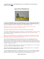
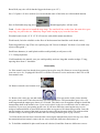
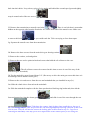
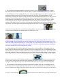
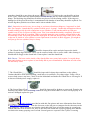
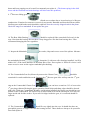
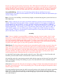
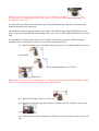
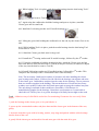
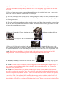
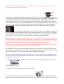
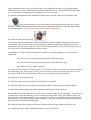
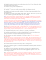
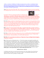
You can find the rest of my web pages here
Last Updated November 12, 2005
T-90 Rebuild Guide
The T-90 Rebuild Video can now be purchased here
Sorry, if you wanted the Model 18 Transfercase Rebuild Guide you will need to go to: Here
In my search for detailed instructions for rebuilding a T-90 I found there was little in the way of
helpful information available. I did find a local transmission guru to answer some of my hardest
questions. Since I considered the service manual to be inadequate for a beginning rebuilder, I bought
a T-90 and practiced taking it apart and putting it back together again. I have practiced it so many
times now that I've lost count, so I feel somewhat qualified to pass on what I have learned. (I have
successfully rebuilt over ten T-90s since I first posted this guide) If you wish to follow these
instructions, you will need to manufacture the tools listed below. If you prefer to use the heavy grease
method of assembling the cluster gear, please feel free to do so. Just skip the instructions that require
special tools and figure it out for yourself using an illustrated parts breakdown (IPB). I found that my
hands are far too big to do that type of work so I made the special tools I describe below to assist me.
These procedures should work for every top shifted T-90. I know there are some step variations with
the side-shifted models but I haven't incorporated those into this guide. Use these instructions at you
own risk. Even though over fifty T-90s have been rebuild using them, there are still probably a few
glitches left to fix. It will be very beneficial for you to learn the names of all of the parts from an IPB.
I also recommend that you keep your old parts and practice assembling the transmission before you
do the final rebuild. Good luck, I hope you have as much fun as I did.
As other people use these instructions and provide me with feedback I will post their comments. Merl
was my first guinea pig and he, Rick Grover (http://www.public.asu.edu/~grover/willys), Frank
Woods, Dr. Vern, Mike, Paul and numerous others have provided some great feedback. Matt Clark
was nice enough to provide me with a typo corrected copy of this page. I have also taken the liberty
of taking a quote from one of Richard Needham's WillysTech postings about sealed bearings. Below
are a couple of web links to the CJ-3B web site that show the T-90 illustrated parts break down.
http://www.film.queensu.ca/CJ3B/Photos/Parts/Transmission.gif
http://www.film.queensu.ca/CJ3B/Photos/Parts/TransmissionCutaway.gif
I can be reached for comments at [email protected]
Dr. Vern - First, I'd highly suggest pre-ordering the usual replacement parts. After disassembling
mine, I had some trouble getting the parts in a timely manner. In the several weeks that passed, I
forgot much about how it all went together. Just by pulling the top cover, you could inspect most of
the major parts without much disassembly.
Merl - My T90 rebuild is finally done, and I must say that it went along much easier than I had
expected. I used Rick's rebuild guide and a blowup picture for part name reference, never even looked
at the shop manual for instructions on the rebuild. Overall, I'll give Rick's manual a hearty
recommendation. I'm doing this from memory so I hope I'm not leaving anything out, but here are the
more notable points and observations that I encountered...
As for my original problem...
T-90 shifts easily into R & 1st, never grinds at all even while rolling. However, after getting warmed
up 2nd and 3rd would grind unless I shifted really slowly. The main problem was the worn 3rd gear
synchro riding up too high on the surface of the input shaft bevel. The rear face of the synchro was
scored where it had been hitting the small teeth of the input gear. But the *cause* of this looked to be
the two shims between the rear shoulder of the mainshaft and the bearing spacer. I don't see these type
shims in the shop manual (early Universal Jeep) and Rick said he hadn't come across them either.
They sit between the shoulder of the mainshaft and the bearing spacer. They are cupped a little so that
the outside circumference points in toward the large sliding gear (1st/R). My transmission had two of
these. My local parts guy, Leo, said that while not typically used they are used to adjust the mainshaft
play. He said that the idea was to align the rear face of the bearing spacer with the rear face of the
bearing adapter. When installed, you want the rear faces of these two pieces to be flush. Any
misalignment should be on the side of not enough shims rather than too many. It seems that the inside
ring of the rear bearing rests on that spacer. Too many shims between the shaft's shoulder and the
spacer would cause the 3rd gear synchro to ride too close to the beveled input shaft all the time
causing premature wear. That's my theory anyway. When I put it back together I did a test fit before I
put the rear bearing on and decided to not put a shim back in there. Another theory I have about this is
that the tighter than normal mainshaft was allowing the smooth 1st/R shift. Maybe a sort of automatic
double-clutch thing happening in there.
SBart79631 wrote: I would suggest that every time the tranny is removed or rebuilt, that the bronze
bushing in the center of the flywheel be replaced. This is an inexpensive item and not too much more
work to do. The worst thing in the world is to rebuild the trans and have it go bad again in a couple
hundred miles cause the input shaft is wobbling all over, take it from me, I learned the hard way.
Also, in the excitement of completing the job, a friend forgot to fill her up with gear lube and drove it
around the block, and right back up on the jack stands. Steve, 46cj2a restoration in 1972, currently
working on 48 cj2a
I agree with Steve on this. I've had several folks that have rebuilt their T-90s, only to still have the
same problem with gears grinding during the 2nd and 3rd up-shift. After going back and replacing the
crankshaft pilot bushing, the problem went away.
Mike Harris wrote: Joe Van Slyke & I got together Sunday to rebuild his T90, it seemed to go well
but had a few, if not problems at least some questions. Joe also got my thumb a good one w/ the ball
peen, proof that it's better to have an assistant so's you have someone else's thumb to hit! :-)
First, the tranny was apart when *I* got there, and I think Joe said he'd gotten the tranny and transfer
case from separate sources, and already in pieces. I could be wrong, though. Not being there for most
of the disassembly was a major hindrance to reassembly as we had to figure what went where from a
poor-quality exploded drawing.
Joe also got a big box of extra/duplicated parts, which really came in handy. It allowed us to evaluate
each piece side-by-side and pick the one in best shape, creating a "franken-tranny." No oil collector
was in the tranny but we had one in the "spares," may have been damaged because we had to grind off
a little bit of the lip at the top to accommodate the mainshaft.
General comment - Rick practiced several times before the real deal. We didn't practice and I think
that if you skip this step, you should plan for and expect that you will be forced to "practice" or redo
at least a couple of times before it all comes together perfectly.
To avoid confusion I recommend:
(1) Make sketches/notes of difficult assys, especially 2/3 gear hub & synchros & rear bearing. Every
piece in the gearbox goes in 1 way and memory just wasn't good enough, for me at least, even just a
few hours later.
(2) Keep old/new parts separate.
(3) Lay out all parts in assembly order.
A separate section at the end of this instruction covers the Shift Tower. You can get there
quickly by clicking Here.
Special Tool Manufacture
1a. Tool A is manufactured using a 3/4" wooden dowel rod. Cut it to 6 7/8" long. If the dowel rod has
a rough finish, it should be sanded smooth and the ends lightly rounded. I did this using a 2" long
drywall screw mounted in my drill. I turned on the drill and screwed the screw into the end of the rod,
as soon as it snugged up, the rod was spinning nicely. It made sanding very easy.
Merl - Make sure you test fit the dowel through the front and rear holes of the case prior to
assembling the cluster gear, sanding was required in my case.
Also check to insure that the shaft is not too long to fit into the case from the inside.
2b. Tool B is manufactured using a length of 1" diameter metal electrical conduit. Cut it to 2 3/4" long
with a hacksaw. It must be cut straight and any burs removed. Note: Do not use plastic conduit
because it is the wrong size.
Merl - Look for conduit labeled 3/4". You might have to buy a long piece, but it's dirt-cheap. Exact
measurement of the electrical conduit tools is not critical. Within 1/4" inch of Rick's measure is OK,
but do make sure there are no burs on the end of the tool.
Ok, folks here's the skinny on this electrical conduit. The correct size is as Merl described 3/4",
however, you will find that when you measure 3/4" conduit it is 13/16" inside diameter and 15/16"
outside diameter. I hope this clears up the confusion. In addition, Merl is also correct about the length
of tools A, B, and C. They are going to be used as spacers to hold the needle bearings in place during
assembly, so length is not critical.
2c. Tool C is manufactured using a length of 1" diameter electrical conduit. Cut it to 1 7/8" long with
a hacksaw. It must be cut straight and any burs removed.
2d. Tool D is manufactured using a length of 1" diameter electrical conduit. Cut it to 1" long with a
hacksaw. It must be cut straight and any burs removed.
2e. Tool E is manufactured using a 3/4" wooden dowel rod. Cut it to 2" long. The dowel rod must be
sanded to slightly less than 3/4" and will most likely be destroyed in this use. You could also make it
from a piece of brass rod but I used the wooden dowel since I already had some left over.
Other Tools I Used
Brass Drift (any size will do but the bigger the better up to 1/2")
Set of 12 point 1/4" drive sockets (I've been told that some of the bolts are Allen headed instead)
Pair of flat bladed snap ring pliers
. Round tipped pliers will not work.
Frank - Get the right tool to install the snap rings. The small stiff one on the front, the main-drive-gear
snap ring, is a pain in the ers. Jabbed my finger with it trying to pry it out the first time.
Wooden board (I used a 2" X 12" X 24" but size really didn't matter much here)
Work bench (I tried to rebuild it on the floor of the basement but found the work bench easier.)
Ziploc bag and Stove top (These are replacing my old "freezer technique" for those of you with early
copies of this guide.)
Small brass hammer (A small plastic mallet would probably work just as well)
5" C-Clamp (Optional)
If still attached to the transfer case you could possibly need two long thin wooden wedges 5" long,
tapering down from 1" should do.
Disassembly
2a. If the transfer case has already been removed proceed to step (2h). Remove screws from transfer
case rear cover. Or, if equipped with a PTO or Warn OD remove screws and remove the PTO or OD
from transfer case.
2b. Remove transfer case bottom cover
.
2c. Remove the cotter pin, nut and washer
. (You may notice in the picture that the
two gears do not mesh. That's because they are not a matched set. The intermediate gear is for a 26tooth output and the output gear shown is a 29-tooth. They don't even fit together enough to install the
intermediate shaft in the transfer-case. I just set it in place so the view would look close to what you
would see if you were just opening up the case. If you have difficulty removing the nut you can
wedge a hardwood block or brass drift between these two gears to lock them into position. Once the
nut and washer are removed the main gear can be removed from the main shaft. If it sticks two thin
wooden wedges can be tapped in between the rear bearing and main-gear to pop it loose.)
2d. If the shift tower has been removed while removing the transmission proceed to step (2e). Shift
the transmission into neutral, remove the six screws from the shift tower and remove it.
2e. To hold the mainshaft in place until removal is desired, install the front two shift tower screws
back into their holes. Loop a heavy piece of wire under and behind the second speed gear and tightly
wrap it around each of the two screws
.
2f. Remove the transmission to transfer case bolts
. There is one bolt that is somewhat
hidden on the opposite side from the first bolts. It is on the front side of the transfer-case. Make sure
to remove this bolt
or you could crack the T-90 case trying to force them apart.
2g. Separate the transfer case from the transmission.
2h. Remove the three screws from the main drive gear bearing retainer.
.
2i. Remove the retainer, seal and gasket.
2j. Remove the two twelve point/socket head screws that hold the oil collector to the case.
(The oil collector can not be removed at this time so move it out of the way of the
main drive gear as needed.)
2k. Tap the main drive gear forward about 3/8". (Do not try to drive the main gear out at this time or it
will damage both it and the cluster gear.)
2l. Remove the wire and screws from the case and mainshaft that you installed in step (2e).
2m. Slide the clutch sleeve forward on the mainshaft.
2n. Slide the mainshaft complete with the front synchronizer blocking ring backwards, then tilt the
front end upward to clear the cluster gear
and slide it out of the case through the rear
opening.
(Some T-90s have the counter shaft locking plate installed over the top of
the rear-bearing adapter. This will prevent the rear-bearing adapter from being removed. If this is the
case on your T-90 you will need to remove the locking plate as described in step 2o - 2q prior to
removing the mainshaft. This may prove to be difficult due to the limited space for accessing the
reverse idler gear shaft with the mainshaft installed. In this case brute force applied to the locking
plate may be required.)
Merl - Disassembly was easy, the hardest part was getting that locking plate out of the slots on the
rear of the two shafts. As Rick mentioned, mine was inserted from the top down and I couldn't get the
rear bearing adapter plate off without first removing this plate. I bunged up the plate really well and
wound up getting a replacement for it.
2o. Using Tool A or a brass drift, gently tap the countershaft toward the rear of the transmission about
1/2".
2p. Then using a brass hammer also tap the idler gear shaft toward the rear of the case enough to free
the locking plate. In some cases this will be impossible and you will have drive the locking plate out
of the reverse idler shaft.
2q. Remove the locking plate.
2r. Using tool A drive the countershaft out of the cluster gear.
Rick Grover - When you say to drive the counter shaft out, it should be driven out to the rear. The
front hole is a few thousandths smaller that the back hole. Driving it out the front would be much
harder and could stretch the front hole.
2s. Drop the cluster gear into the bottom of the case.
2t. Tap the main drive gear forward and out of the case.
2u Remove the oil collector.
2v. Remove the countershaft cluster gear.
2w. Remove the thrust washers from the case.
2x. Collect the pilot bearings and put them aside. (There is a set of needle bearings known as pilot
bearings that fit inside the main gear. These bearings are much larger than the bearings used in the
cluster gear. The nipple on the front end of the mainshaft rides on these bearings, and they usually fall
into the bottom of the case when the mainshaft is removed.)
2y, Using tool E drive the reverse idler gear shaft out the back of the case.
(This must
be done from inside the case. Caution: do not attempt to drive the shaft into the case from the rear as
this can damage the shaft and the case. Remove the reverse idler gear from the case. Some people
have found it necessary to use a bent piece of rebar to drive the reverse idler gear out of the case. Use
as little force as you can to prevent damage. Whatever you do, don't drive the shaft into the case.)
(Here is a helpful tip. When driving out the reverse idler shaft, stand the case on its tail end. To do
this, place a 3/4" deep-well socket over the end of the shaft, and place 3 more deep-well sockets
around the bottom to provide good balance. Have a second person hold the case in place and drive out
the shaft. This was much easier than trying to hold the case in place laying flat.)
Mike Harris wrote: Reverse idler was a bear. We pounded it out using all-thread since it was long &
flexible enough to get around the slight bend from the front of the case to the shaft.
(Danny M. has provided us with an alternative method of removing the reverse idler shaft. Use a 4
inch C-Clamp, a 3/8" drive 1/2" socket and a 3/8" drive 3/4" deep-well socket. Install the C-Clamp as
shown
with the 1/2" socket against the inside end of
the idler shaft and with the deep-well socket slid over the outside end of the shaft. It took a good bit of
pressure and a couple of taps on the threaded end of the "C" Clamp. Then you tighten it again and tap
it again until the inside end of the C clamp bottoms out. Once it breaks free it can easily be driven out
the rest of the way with your drift)
I think Danny has a great deal more patience than I have. I had a really stubborn shaft that I tried to
remove this way and I ended up breaking my C-Clamp. Now mind you, from start to breakage only
took me 5 minutes. I was using a cheap C-Clamp of very poor quality so here's what I suggest. If you
are going to use Danny's procedure, use the largest, highest quality clamp you can fit into the case and
take your time. Danny's clamp looks a lot better than the one I was using and he's already proven it
can be done. So have fun and if you use this method please let me know how it goes.
2z. Remove the main bearing snap ring using flat edged snap ring pliers.
2aa. Hold the main drive gear by the bearing and gently tap the small end of the shaft onto a board
until the bearing slides down and off the gear shaft
.
Rick Grover - An alternative is several taps with the brass hammer. Worked for me. :-)
2bb. Remove the front bearing washer noting the direction the lip fits on the bearing.
2cc. Slide the clutch sleeve off of the clutch hub, making sure not to drop the
synchronizer plates
inspection.)
three
. (Collect the synchronizer plates and put them off to one side for
2dd. Using flat edged snap ring pliers remove the clutch hub snap ring.
2ee. Remove the clutch hub from the mainshaft.
(You may find that the clutch hub
will not want to slide off the main shaft after you have removed the snap ring. Holding onto the clutch
hub while gently tapping the mainshaft with a brass hammer will usually coax it off. Warning - years
of the clutch sleeve sliding on the clutch hub can cause very sharp edges to develop. Use caution
when handling the sleeve and hub.)
2ff. Remove the synchronizer springs from the hub.
2gg. Remove the rear blocking ring from the mainshaft.
2hh. Remove the second speed gear from the mainshaft.
2ii. Merl has described a shim installed behind the second speed gear on his mainshaft. My
transmission did not have this shim and the parts listing does not show it. It seems these were installed
to bring worn out parts into proper tolerance. If you have this shim remove it now.
2jj. Remove the rear bearing from the mainshaft. If necessary, stand mainshaft on its tail end an use
the 1st/Reverse gear like a slide hammer to drive the rear bearing off the shaft
.
2kk. If you have the large hole bearing adapter, remove the snap ring from inside the bearing adapter
. (You can not use snap ring pliers to remove this snap ring. A flat bladed screwdriver
works just fine. Hook it under the notch in the ring and pry the ring out. Place the bearing on the front
end of the mainshaft again use a slide hammer action to drive the bearing from the adapter.
2ll. Slide Tool A, bearings, washers, and spacer from inside the countershaft cluster gear.
Disassembly is complete.
Cleaning and Inspection
3a. Thoroughly clean all parts with solvent. A good small parts kit will contain needle bearings, snap
rings, synchronizer plates and springs, bearing spacer and thrust washers. Do not waste too much time
cleaning these parts unless you want to use them to practice the assembly and disassembly
procedures. They should be examined to determine common failure items.
3b. The following inspection procedures can be used to determine which parts should be replaced:
1. The main Drive Gear bearing
should be replaced if the center wobbles in the cage,
grinds when spun or makes a squealing noise. I recommend changing it anyway. This bearing may be
changed with a sealed bearing but some things need to be changed if you do this. Whatever bearing
you choose, make sure that it has the groove as shown in the picture. This is where the front bearing
snap ring sits and it is used to hold the bearing in place.
Richard Needham - Well I made it out to the shop and found the bearing number for the front of the
T-90 with the seal. It's a SKF bearing but any good auto parts store should be able to cross reference
to another brand.
SKF---6208-2RSNRJ/EM
Note: You must remove the seal from the inside of the bearing, to allow the 90W oil to lubricate the
bearing. Also there is a drain-back hole in the front of the transmission that must be plugged if you
use this bearing. When you remove the 3 Allen bolts to take the cover off the front of the
transmission, you will see there are 4 holes in the transmission the one with no treads is the drain
hole. Plug it with silicone or tap it and use a small pipe plug. Otherwise the sealed bearing will do no
good because the oil will run out the drain hole.
I tried to locate the bearing that Richard used but was unable to find it. I did some local research and
found this sealed bearing.
MRC brand Part #208-SZZG
I found them at Purvis Bearing in San Antonio (210) 299-1010. They cost $31.25 (At the time I
authored this July 2000) and they had them in stock. They said they would mail order them to credit
card customers. They also said to leave the seals installed on both sides because the bearings were
designed to run for over 100,000 miles without servicing.
Update: (Nov 2005) Mike Harris has reported paying $48.86 plus tax for his bearing at the Purvis
Bearing in Austin and I recently paid about $51 out the door here in SA. These beings have gone up a
lot in 5 years.
I'm going to repeat at this time, If you are using this sealed bearing and you have the long-shaft maingear-shaft, you must plug the hole in the pilot bearing race to the outside of the transmission or it will
leak badly.
If you determine that you need a new Main Drive Gear Shaft make sure that you order the right one. I
don't have the different lengths on hand but it you measure the length they should be able to tell you
which one you have.
2. The front Bearing Washer should be replaced if bent or scored.
Most of them I
have removed have looked like the one on the right. A new one should look like the one on the left.
3. On the Main Drive Gear (Referred to by some as the Input Shaft) inspect the pilot-bearing race for
scoring and pitting. Inspect all oil passages to insure they are clear. The inside diameter can be
checked by measuring the diameter of the pilot shaft on the Mainshaft adding this size to the twice the
diameter of a new pilot needle bearing. The sum of these diameters should be within .001" of the
inside diameter of the Main Drive Gear pilot bearing race. An easier way to check this is to install
new bearings in the race and insert the mainshaft into the bearing. There should be virtually no
wobble of the shafts. If this fit is loose it will cause the pilot bushing in the engine crankshaft to wear
out quickly. Check the gear teeth and blocking ring teeth for signs of wear and breakage. The beveled
surface the blocking ring rides on should be smooth and free of cracks or pits
of these items is damaged you should replace the Main Drive Gear.
. If any
Long Shaft and Short Shaft Main Drive Gears have been identified as being different in more ways
than just length. The long shaft has an oil hole drilled from the inside of the pilot-bearing race to the
other side of the front main bearing race. It is the dark spot in the bottom as shown in the picture. It is
easier to see in this photo taken from the other side. If you install a sealed bearing during installation,
you must seal this hole or the transmission will leak.
4. Countershaft gear Oil Collector should be examined for cracks and dents. If damaged replace it.
Many people recommend leaving this assembly out of the transmission, but I recommend against this.
The Oil Collector retains oil around the front end of the Countershaft Cluster Gear. This feeds oil into
the needle bearings. In the event that you ran low on oil the collector would continue to feed oil onto
the bearings. The Oil Collector will also help to prevent the oil from foaming at high speeds. Note the
difference between the old oil collector and the new one.
The new one at the bottom
is not as good as the old one and will require trimming the edge to get it to fit without dragging on
main-gear. If you choose to buy a new oil collector make sure you are ready to trim it if necessary.
5. The synchronizer blocking rings should be inspected for broken teeth and worn mating surfaces.
The mating surfaces that fit against the Main Drive Gear and Second Speed Gear should have small
grooves machined into them with raised surfaces that come to points between the grooves and should
be free of cracks and chips
. When installed on the Main Drive gear and Second speed
gear there should be a gap where the arrow is
. I believe the gap should be at least
0.010" wide. I don't have any documentation to back that up, just my minor experience with these
things. The blocking ring should not fit all the way down over the mating surface. If the rings are
damaged or if the grooved surface is contaminated with chunks of metal they should be replaced. I've
tried to dig those particles out of there and it isn't worth the effort.
Merl - Inspection was also easy, just so long as you know what these things are *supposed* to look
like. For example, I stated that my synchros looked good...*wrong*. I made this assumption without
actually making a side-by-side comparison to new synchros. Turns out that while my 2nd gear
synchro was ok, the 3rd gear was badly worn. Take your mainshaft assembly completely apart and
take a good close look at everything. With everything apart take your synchros and put them on the
beveled edge of the 2nd speed gear and the input gear. If either the beveled edge of the gear is worn
or the rear or inside of your synchro is worn replacement is needed. As Rick suggests, you might as
well just go for new synchros, they're cheap.
6. The Clutch Sleeve
should be inspected for cracks and pits. Inspect the inside
splines for sharp edges and burs. These can be removed with a file or crocus cloth. After cleanup, it
should still fit snugly on the clutch hub. If not replace it and the clutch hub.
Rick Grover - The burrs on the inside of the clutch slider were pretty bad on mine. I worried about
them and whether or not to replace it, but finally did as you recommended, filed them off with a fine
file and emery cloth.
7. The Clutch Hub
should be inspected for sharp edges and burs on the splines.
Caution should be used when handling a used hub as it could have very sharp edges. Using a file or
crocus cloth, remove any burs. Check fit on the Mainshaft and inside the Clutch Sleeve for snug fit. If
it does not fit both pieces snugly, replace it.
8. The Second Speed Gear
should be inspected for broken or worn teeth. Examine the
blocking ring surface area for scoring. Check for snug fit on main shaft. If it does not fit properly or if
teeth are damaged replace the gear.
Frankie Ladwig provided us with this fine picture and some information from Jason
at Mile High Jeep Rebuilders. Note the chevrons on the left gear as compared to the chevrons on the
new right gear. These chevrons are what the clutch hub slide over to lock the tranny in second gear.
If these chevrons wear down too far, they do not allow the clutch hub a proper gripping area and this
can lead to the tranny pooping out of second. Second gears are expensive but if yours is wearing
down and been popping out of second I recommend you replace it. (The detent spring in the shift
tower and the front and read main bearings will also cause this problem.)
9. 1st/Reverse sliding gear
will take severe abuse due to its not having a 1st/Reverse
synchronizer. Examine for broken or excessively worn teeth. Rounded and shaved teeth can still be
used but gears with broken teeth should be replaced. Note the severely chipped tooth in the photo.
Check for snug fit on mainshaft. If not replace the gear.
10. The Rear Main Bearing
should be replaced if the center hub fits loosely in the
cage. Note that this bearing does not have a snap ring groove like the front bearing does. I also
recommend changing this one regardless.
11. Inspect the Mainshaft
for cracks, chips and excess wear of the splines. Measure
the mainshaft pilot shaft
to determine if, with new roller bearings installed, it will be
within .001" of the inside diameter of the Main Drive Gear. If not replace it. If this fit is loose it will
cause excessive wear on the engine crankshaft pilot bushing.
12. The Countershaft Gear Set (Known by most as the Cluster Gear)
should be
st
examined for cracks and broken teeth. Because the 1 /Reverse gear rides well up onto the 1st gear
ring on the Countershaft Cluster Gear
, you can have as much as 3/8" of wear to the
st
1 gear ring without affecting the gear's operation. Small chips and sharp edges should be dressed
with a file. With new Countershaft Washers, and bearings installed, the cluster gear should have no
wobble on the countershaft. The easiest way to detect inside wear on the cluster gear is to run your
finger inside and feel the surface. If you can feel ridges inside the gear, it is worn and should be
replaced.
13. The Countershaft
should fit very tightly into the case. It should also have no
perceptible grooves or ridges worn into the bearing surface. These shafts are cheap so do yourself a
favor and replace it.
14. The Reverse Idler Gear
will have worn teeth. These should be dressed with a file
to eliminate small chips or sharp edges that could be broken off and left inside the transmission.
Check the fit on the Idler Shaft for wobble. The gear has a bronze bushing that should look like this
. If it doesn't fit well or is missing large sections of teeth it should be replaced.
15. The Reverse Idler Gear Shaft should be inspected for chips or wear grooves. Since these shafts are
cheap, if you suspect the shaft is worn then replace it.
16. The case must be thoroughly cleaned and inspected for cracks, giving extra care to the bottom and
around each case opening. Ensure the countershaft and reverse idler shaft fit very snugly into the case.
Do not leave any old gasket material on the mating surfaces. You will notice that as the years have
passed, people have tried to seal their leaking cases by tightening the screws tighter. This leads to the
edges around the threaded areas being pulled out from the case. This is no big deal except that it will
keep you from getting a good seal. Use a file to level the edges of the threaded holes. Make sure to
keep the file flat and don't dig into the metal. Remember the intent is to level the surface again.
Frank - Buy your small parts kit from:
Four Wheel Drive Hardware USA/Canada 1-800-333-5535
Int'l 1-330-482-4924 or 1-330-482-5560
Fax 1-330-482-5035
www.4wd.com
Columbiana, OH
It's the best.
Rick - I agree with Frank on this one. I've seen small parts kits from a lot of different places but the
one from Four Wheel Drive Hardware is the most complete. By the time you add the parts that the
other kits don't have, the price is higher to buy from anybody else. If this situation changes or
somebody has a different experience please let me know.
Dr. Vern - Did any of the later model T90's use a neoprene lip seal at the front? On mine, the front
seal was a flat cork washer sandwiched against the face of the bearing by the bearing retainer. The
bearing that I removed (original?) was shielded, but not sealed, on both sides. The shields were
probably enough to slow the flow of oil to the point that the cork washer could handle it.
I had been pondering installing some sort of neoprene lip seal at the forward bearing retainer. These
are those common type of seals used on the transfer case, timing chain cover, and other applications. I
decided against it because the bearing retainer wasn't thick enough. There was not enough material to
cut away to press in a seal. Nor was that part of the input shaft smooth enough for a seal. I suppose I
could have rigged up a toolpost grinder on the lathe, but the sealed bearing idea was looking a whole
lot simpler.
When I got my small parts kit home, I sorted through this wonderful mixture of needle bearings,
thrust washers, gaskets and so on. (I kept picturing Merl's boys playing in the grease.) The kit didn't
have the cork washer, which I wasn't going to use anyway. Instead there was a small neoprene seal,
sized to fit over the input shaft.
So one very long, not necessarily relevant story later: Did some later model T90's use a neoprene lip
seal for the input shaft? It looks like the bearing retainer would have to be different to hold it in place,
and the finish on the shaft would have to be smoother. I don't plan to add one, because it would soon
fail anyway if there was no oil on the shaft due to the sealed bearing. I'm just wondering, that's all.
Jason@MileHiJeep - We have new T-90 bearing retainers that are machined to accept a
metal/neoprene seal. When our tech rebuilds our T-90's, he said that he polishes the input shaft to give
a better sealing surface.
Rick - If you are not installing a sealed bearing I highly recommend buying these parts from Jason at
Mile High Jeeps.
Rick - Before ordering your new parts you should evaluate the expense involved with doing your
rebuild. When I first wrote this guide (1998), a complete rebuild of a T-90 with new bearings and
seal ran about $125 and it still does. A new T-90 came in between $500 and $700, so adding in
another $200 worth of parts to your list still made sense. In the last year the price of new T-90s has
dropped dramatically. You can buy a new T-90 without the shifter today (Dec 2000) for $400. If
your rebuild is going to cost you $300 in parts then you might want consider buying one of these
trannys instead. Therefore, you should do a careful inspection of your parts prior to ordering new
parts to determine what you will need.
Assembly
Merl - I have to *highly* recommend Rick's technique using the electrical conduit. After I cut the
tool A, B, C, and D and finally understood the way Rick's method works, I put newspaper on our
kitchen table, got my 6 & 8 year old boys to count out 4 piles of 22 needle bearings each, gave them a
cup of grease and let THEM put the thing together. Of course I supervised to make sure everything
was going in the right order, but the fact that my 6 year old did most of the work should tell you how
easy these tools make it (plus, my boys had a good time with the grease).
Mike Harris: The dowel/electrical conduit for the countershaft needle bearing assy made a fussy job
easy. This "tool A, tool B, Tool C" cha-cha-cha is the way to go. Don't do it the conventional way
unless you want to make yourself nuts trying to hold four rows of needle bearings in with grease (with
both 6-7/8"-long index fingers), using the other hand to hold the countershaft, your other hand to hold
the plastic hammer, leaving your other hand free to hold the shop light to watch yourself catch a
needle bearing with the countershaft & drive it sideways into the case.
4a. Install the Front bearing washer onto the main drive gear. This washer is a form fit washer and
should be put on the shaft so that it will match the contour of the bearing.
4b. Install the main drive gear bearing onto the shaft with the snap ring slot forward. Grease the shaft
before installing the bearing. This bearing is a press fit to the shaft but it can be installed using the
following method.
Mike Harris: We heated the front & rear bearings by putting in a Ziploc and putting the bottom end of
the Ziploc into boiling water - boil-in-bag-bearing, yum. This got the bearings hot enough that I don't
think freezing was needed.
You must install the bearing onto the shaft in one quick motion or the bearing will contract around the
shaft. If the bearing fails to seat all the way onto the shaft you can persuade it using a brass drift.
Make sure to only tap on the inside edge of the bearing cage. If you use the outer edge of the bearing
you could damage it.
Make sure the snap ring groove is forward or you will have to do it again.
This
bearing had to be removed and installed the right way. If you think I did it just for the photo, you
don't know me very well. :-)
4c. Install the snap ring onto the main drive gear using flat bladed snap ring pliers. (This snap ring
holds the bearing on the main gear.)
4d. Install the front bearing snap ring on the outside of the front bearing using flat bladed snap ring
pliers. (This snap ring holds the front bearing in the case.) You are done with the Main Drive Gear for
now.
4e. Assemble the Countershaft Cluster Gear assembly. At each step that says "install" during the
assembly of the Countershaft Cluster Gear use a liberal amount of grease.:
4e1. Stand the cluster gear on its large end on top of piece of cardboard and insert Tool A
into the hole.
4e2. Install Tool B
and Countershaft Spacer over Tool A
in that order.
Merl - Make sure you grease the middle spacer...I forgot. But, I was able to put a little light oil in the
lube hole in the middle of the gear so I didn't take it all back apart.
4e3. Install one bearing washer over Tool A
.
4e4. Install 22 needle bearings into the space left between Tool A and the Cluster Gear
shaft.
4e5. Lifting the gear while holding the cardboard over the end, lay the cluster Gear on its
side.
4e6. While holding Tool A in place, push the needle bearings into the shaft using Tool C
and remove Tool B
.
4e7. Again using the cardboard to hold the bearings and spacers in place, stand the
Cluster gear onto its small end.
4e8. Install the 2nd bearing washer and 22 needle bearings
.
4e9. Lifting the gear while holding the cardboard over the end, lay the cluster Gear on its
side.
4e10. While holding Tool A in place, push the needle bearings into the shaft using Tool
D and remove Tool C.
4e11. Stand the Cluster gear back onto its large end.
4e12. Install the 3rd bearing washer and 22 needle bearings, followed by the 4th washer.
4e13. Using the cardboard to hold the bearings in place, stand the Cluster gear one last
time back onto its small end and remove Tool D (It may be necessary to insert tool B part
of the way into the shaft to remove Tool D).
4e14. Install 5th bearing washer and 22 needle bearings, followed by 6th washer. This
completes the assembly of the Countershaft Cluster Gear assembly.
Note: The last tranny I built had 4 washers of clearance left after installing the cluster
gear bearings and washers. If allowed to ride like this the bearings can migrate and twist
in the cluster gear. I added these washers into the count for the bearings. I never put more
than two washers together in the buildup. This meant that once I found out how many
washers were needed, I had to take it all back apart again to group the washers into pairs.
The only thing I can think of that would have caused this, is a difference in
manufacturing lengths for the bearings. I don't have a micrometer so I wasn't able to
check this out. The key here is to get the bearings to fit firmly but not tight on the ends.
Frank - I didn't use any of slick Rick's tool tricks. I'm wondering if someone else can verify if this
works:
1. pack the bearings in the cluster gear, or let your kids do it.
2. grease up the countershaft washers and place them and the cluster gear in the bottom of the case,
gently.
3. insert the main drive gear with its bearing, washer, snap rings and packed with the roller bearings
into the front of the case.
4. gently lift the cluster gear and mesh its forward most gear with the main drive gear.
5. gently insert the countershaft through the back of the case and into the cluster gear .
6. insert the mainshaft assembly through the back of the case and gently wiggle/insert into the main
drive gear
4f. Place the large thrust washer coated with assembly grease into position in the case. It goes to the
front of the case with the brass side toward the cluster gear.
4g. Place the small steel thrust washer heavily coated with grease in the case. The steel thrust washer
has a steel tab that will sit on a shoulder in the case. This tab prevents the washer from spinning when
the cluster gear rotates.
4h. Place the small brass rear thrust washer onto the cluster gear. Most cluster gears have two notches
cut into the small end for the thrust washer to fit into. The smaller thrust washer goes to the rear with
the brass side toward the steel washer.
4i. Place the Countershaft Cluster Gear into the case
with the large end to the front.
It will just lay in the bottom for now.
4j. Place the Oil Collector in position in the case.
Do not install the screws at this
time. You will note on the left side of the photo some extra parts that your T-90 doesn't have. This is
the shift mechanism for the side shift tranny. You can build a side shift T-90 to be a top shifted T-90.
Frank - Don't forget to install the oil collector in the right order because it won't go in last like I
thought it would. Unless you want to practice disassembly/assembly one more time.
4k. Install the Main Drive Gear into case from the front.
rest against the front of the case.
The bearing snap ring will
Dr. Vern - I found it easier to install the pilot bearing rollers before installing the main drive gear. I
have a magnet on a stick that worked great for handling those teeny little rollers, too. Things got
pretty slick using assembly lube.
Dr. Vern - Keep in mind when you put the main drive gear and its bearing in the front of the case,
you will have to back it out partway later. Since I did the sealed front bearing mod, I decided to seal
between the big snap ring and the case too. When I had to back out the bearing and shaft as required,
the sealer had partially set and came apart in globs. I had to scrape it clean and reseal it. So if you plan
to seal it like I did, wait until just before installing the bearing retainer to add the sealer. I also cut a
piece from the snap ring of the old bearing, and used it to fill the gap in the new bearing's snap ring.
Hopefully this will help me get a better seal without that big gap. If you are not replacing the bearing,
a piece of thin metal the appropriate size would work just fine. If you are using the stock front seal
and open bearing, this will not be needed.
4l. Install the countershaft through the cluster gear from the rear of the case.
It may
be necessary to stand the case on its end to get the thrust washers to align with the countershaft. Take
your time and don't use too much force to insert the countershaft. If it isn't going in, then washers
aren't aligned properly. It's ok to gently tap the end of the shaft with a brass hammer but any more
force than that is too much. As the countershaft slides in, Tool A will slide out. Let Tool A fall out on
its own if possible. This will help keep the thrust washers aligned. Make sure the locking plate slot
that is cut into the shaft is at a 90-degree angle to the case hole for the Reverse Idler Gear Shaft.
Do not install the shaft all the way or you will not be able to install the locking plate.
As per the manual, once installed, the cluster gear should have between .012" and .018" of clearance.
This should be obtained using thrust washer shims. I've never seen one that had that much clearance.
They usually have less than .005" clearance and I haven't had any trouble with them.
Dr. Vern - The rear countershaft thrust washer gave me fits when it was time to lift the gear into
place to install the countershaft. It kept staying down, not lining up. Then I looked at how the keyed
tabs were oriented. I had them aligned vertically at first. When I turned the gear 90 degrees so the key
tabs were horizontal, the thrust washer did not slip down as I lifted the gear into place.
Rick - Some cluster gears do not have the slots cut into the small end for the tabs to fit into. If yours
does not, you will need to either flatten the tabs or break them off.
4m. Place the reverse idler gear in position with the larger center hub boss pointing forward. Install
Reverse Idler Gear Shaft from the rear of the case. Watch the position of the locking plate slot. Do not
install the shaft all the way or you will not be able to install the locking plate.
4n. If you have the shim identified by Merl and you wish to use it, install it on the mainshaft now. I
feel these were only used to compensate for worn parts, so with all new bearings and blocking rings
you should not need them.
4o. Install the second speed gear onto the mainshaft with the blocking ring mating surface pointing
forward.
4p. Place the rear blocking ring on the second speed gear.
4q. Install the synchronizer springs into the clutch hub.
They should be installed in
opposite positions with one in the front and one in the rear. One end of each spring should fit into the
same synchronizer slot. I have no idea why they are installed like this but every old transmission
manual I have been able to find shows the springs installed this way. If you installed them the other
way, I don't think it would hurt but why fight 50 years of experience?
4r. Slide the clutch hub onto the mainshaft with the longer, narrow center boss pointed forward.
This photo shows the rear of the clutch hub with the shorter but wider boss. Some
folks have confused the direction of this hub during installation and this prevented the transmission
from going together. (Clarification for this step provided by Doug Karr)
4s. Install the clutch hub snap ring.
4t. Heavily grease the synchronizer plates and hold them in place while installing the clutch sleeve
over the hub. There are three slots in the blocking ring that the synchronizer plates must fit into to
install. Make sure the shift fork groove is to the rear of the mainshaft. It can go on the other way, but
it will prevent you from installing the shift tower later.
4u. Stand the T-90 onto its front end with the main drive gear shaft hanging over the edge of the
workbench.
4u1. Insert Tool A into the pilot bearing hole of main drive gear.
4u2. Grease needle bearings and insert them into the main drive gear.
4u3. Remove Tool A while rotating it.
4v. If you have the large-hole bearing adapter you will now install rear bearing in rear bearing adapter
and install snap ring. This bearing is also a press fit and can be tapped in using a brass drift. If you
have the small hole adapter the bearing will just sit in an shallow relief in the adapter.
4w. Place the T-90 back down flat.
4x. Slide the main drive gear as far forward in the case as possible.
4y. Slide the clutch sleeve as far forward as possible without releasing the synchronizer plates.
4z. Install the front blocking ring on the main gear with grease to hold it in place.
4aa. Install the mainshaft from the rear of the case and insert it into the pilot bearings. You will need
to lift the front of the mainshaft up over the second gear ring on the cluster gear and then allow it to
drop into place in the pilot bearings. If you can't get it to go over the second gear ring, you don't have
the clutch sleeve far enough forward on the mainshaft. The three synchronizer plates will need to fit
into the notches in the front blocking ring.
4bb. Slide the main drive gear back into case until outside snap ring is firmly against the case.
4cc. Install the screws in the Countershaft Cluster Gear Oil Collector.
4dd. Install the front bearing retainer gasket and bearing retainer oil seal if used. (Mine used a rubber
seal installed in the bearing retainer.)
4ee. Install the bearing retainer and tighten screws.
4ff. Install the 1st/reverse gear onto the mainshaft with the shift fork groove forward.
4gg. Install the rear bearing spacer on the mainshaft. (If you forget this part the mainshaft will have
too much free play.)
4hh. Install the rear bearing adapter with the bearing onto the mainshaft. This is also a press fit. I used
a 2" piece of the PVC pipe to drive the bearing down onto the shaft.
Merl - The only other problem I had during assembly was getting the rear bearing pressed onto the
mainshaft prior to inserting the mainshaft into the case. I tried Rick's 2" PVC pipe technique, but it
tends to shoot small shards of plastic off into the bearing.
I wound up using a blunt nose chisel on the inner race, a tap on the chisel with a hammer at 90 degree
increments around the bearing race did the trick. It should be noted at this point that even though Merl
had success using a steel punch to drive the bearing on, this is not a recommended practice. On
occasion I have been known to hammer steel on steel. Sometimes this has met with success but on
occasion I have had less than positive results. Rick's recommendation below should be followed.
Rick Grover - Brass hammer taps worked for when I did my T-90, I never hit anything with steel. Get
a brass hammer and/or a brass punch. They are about $10 each. They get all dinged up and even shed
little brass flakes sometimes, but they do not scratch or mark the machined steel surfaces.
4ii. The mainshaft washer and nut may be placed on the mainshaft for safekeeping.
4jj. Install the countershaft and reverse idler gear shaft lock plate. I've found a lot of these are not
made to specifications and need to be filed or ground down to fit properly.
4kk. Tap shafts into case until the locking plate is held firmly in place. ** See note at bottom of
assembly guide
Dr. Vern - The front bore of the countershaft is known for leaking. The end of the shaft is about 1/16"
inside the case when fully assembled. I plan to put some sealer in there when I bolt the transmission
to the bellhousing. The flat surface of the bellhousing will sandwich the sealer in place. Naturally you
don't want to use too much, but just enough to fill that cavity. I'll let you know how it works after I get
the jeep back on the road.
4ll. Position the clutch sleeve and 1st/Reverse gear into the neutral position.
4mm. Place the shift tower gasket in position and install the shift tower housing with the shift forks in
the shift grooves.
4nn. Install the six screws and tighten. (The shift tower is usually removed and installed in the
vehicle. If you are just putting the shift tower on for safe keeping do not tighten the screws. This
could damage the gasket.)
Merl - Oh, and one last thing. While you've got your transmission output gear off (you've got to have
it off to separate your TC and transmission), count the number of teeth on that sucker. You never
know when you're going to run across a used Warn OD at a decent price and wouldn't you just HATE
to miss out because you didn't know or guessed wrong?
** Rick - On the last T-90/Model 18 rebuild I encountered a new problem. I installed the locking
plate from the bottom instead of the top. When I bolted the T-case to the T-90, the locking plate
interfered with the mating and I had to pull it all back apart to swap the plate. Make sure you check
this fit before applying gaskets and sealer. Another guy was rebuilding his IH Scout T-90 and had the
same problem. His info is printed below.
Gary- Major lesson learned last night. There's already some added comments in your text regarding
the locking plate that secures the reverse idler shift shaft and the cluster gear shaft. On IH Scout using
the T90/T18 combo, the locking plate MUST be installed from the top
, so that it is a
right-side up "T". I put mine in from the bottom, put gasket shellac on all the gaskets and cranked
everything down tight. When I filled both with the requisite 6 pints of gear oil and started the engine,
I had a puddle on the floor pretty quickly. Tried quick fixes like shellac on the threads of the bolts that
join the T18 and T90, but still had good flow. Took the two units apart last night and found that the
locking plate is interference with the fit. Kinda like slipping a dime between the mounting surfaces.
Dr. Vern- During assembly, the shaft locking plate on the rear must be correctly positioned to fit into
a recess on the front of the T-case. Rick's guide mentions this, and how one guy had the plate keep the
T90 and T-case from pulling together correctly. I used the gasket as a template and traced the outline
of the recess with a magic marker. When the two shafts were still protruding about an inch, that is
when I fit the locking plate into the shafts' grooves. That allowed me to keep everything in correct
alignment as I drove the shafts all the way in.
Rick - Even with a correctly aligned locking plate it is possible for the plate to interfere with the Tcase installation. This will cause one of two things to happen. Either the tranny and T-case will leak
terribly through an unsealed gasket or the tranny will bind up and not turn. The binding is caused by
the T-case cocking the Rear Main Bearing. The solution to this problem is to trim the locking plate
with a file or grinder to make it fit inside the hole in the T-case.
Dr. Vern - I felt like I had discovered the cure for cancer or something when I finished the rebuild. It
was not hard at all. It is just a matter of following the steps in the correct sequence. Being familiar
with all the names of the parts helped, too, as you read the instructions.
Dr. Vern - Since you must have the shift tower off when removing or installing the T90, I'd suggest
taping a piece of cardboard across the open case. I think I'd cry if some crud from under the body fell
in during the installation.
Rick - Here's new bit of information for you. Tom Jacoby's tranny went together beautifully and
worked fine until it was bolted to the T-case. Once it was bolted up everything bound up tight and
was very hard to turn. This sounds a lot like the binding locking plate mentioned above and therefore
that was inspected and ruled out. In the end the cause of his problems stemmed from the bearing
spacer being too thick (0.031") for his tranny. This forced the Mainshaft forward too far when the Tcase was installed against the tranny. On most T-90s this thick a spacer would not have been a
problem but on his the other parts had larger tolerances too and they combined together to create an
assembly that was too long to fit the case. If you encounter this problem you may need to find a
thinner spacer. A new spacer that was 0.021" thick worked just fine for Tom.
OPERATIONAL CHECK
5a. Shift the tranny into reverse and rotate the main gear. On T-90s with the felt seal in the front
bearing retainer you will have to use some force to rotate it. The mainshaft should rotate in the
opposite direction with no grinding or scraping sounds.
5b. Shift the tranny into first gear and rotate the main gear. The mainshaft should rotate in the same
direction only much slower.
5c. Shift the tranny into second gear and rotate the main gear. When you do this you will need to hold
the rear bearing retainer in place or it will allow the mainshaft to slide out the back of the tranny and
the pilot bearings will drop to the bottom. The tranny should shift smoothly into second gear and the
mainshaft should rotate smoothly in the same direction.
5d. Shift the tranny into third gear. The tranny should shift smoothly into second gear and the
mainshaft should rotate smoothly in the same direction.
Bob Stewart: Caution: In a November 1958 Jeep Service and Parts News, They note that there are 2
different size bolts to hold the T-case to the transmission, 1" & 1 1/8". They warn that improper
assembly can lead to gear damage and leaks. They want the two 1" bolts in the lower left and lower
right.
Rick: I looked this warning over very carefully and I agree that installing the 1 1/8" bolt in the lower
left corner position would damage the reverse idler gear. I was unable to find a reason for the shorter
bolt in the lower right hole unless they were concerned about confusion as to which side was which.
ASSEMBLY CHECKLIST OF THINGS OFTEN FORGOTTEN
1. Main gear snap ring.
2. Main shaft Snap ring.
3. Clutch hub installed with larger hub forward.
4. Clutch hub sleeve installed with the shift fork groove to the rear.
5. 1st/Reverse gear installed with the shift fork groove forward.
6. Clearance for the countershaft locking plate between the cases.
7. Non hardening sealant on every bolt that penetrates to the inside of the case. I've decided to agree
with Dr. Vern on something that he said long ago, "RTV gasket sealers should be outlawed." I found
that stuff in every possible orifice in the last case I rebuilt. It was causing oil starvation to the
bearings.
8. Running the Tranny through the shifts prior to installing it in the vehicle.
ON REBUILDING THE SHIFT TOWER
Thanks to Ron Cox and Reed Cary I have been able to add the Shift Tower rebuild instructions to this
guide. Without their help this would not have been possible. Thanks guys. In the research that we
have done it has come to light that there are two different shift towers available for the T-90
transmission. One is in the M-38 and looks like this. It was designed to be waterproof and seems to
have a more rugged design. The second one I call the other T-90 shift tower and it looks like this. It's
is possible that the M-38 shifter was used in other military jeeps as well, if so please let me know and
I will add them to the list.
DISASSEMBLY
Remove shifter fork pins from the second and high-speed shifter-fork and the low and reverse speed
shifter-fork. In some shifters this is a split pin and in others it will be a hollow pin that is staked in the
end. The split pins can simply be driven out with a pin drift but the staked pins must have the staked
end drilled off first. Place both shift rails into the neutral position.
The M-38 shift tower will have two 3/8-inch countersunk head pipe plugs at the rear of the shift rod
rail holes. Remove these. For other models this is N/A.
Verify that the rods are both still in the neutral position. Drive the second and high-speed gears shifter
rail to the front until the rail hole expansion plug can be removed. Carefully slide the shifter rod
forward while rotating the shift lever notch in the rod toward the bottom of the tower. Do not allow
the notch to pass the poppet ball while it is pointed toward the top or the poppet ball and spring will
become trapped in the notch. If this happens you can force the poppet ball back into the hole by
rotating the shaft with a pair of vise-grips. Caution: as the rod slides past the poppet ball, the natural
tendency is for the ball to shoot out. Cover the hole with a rag. Remove the rail and the second and
high-speed gears shift fork.
Drive the low and reverse speed gears shifter rail to the front until the rail hole expansion plug can be
removed. This rail does not have the notch to worry about so it should be a little easier to deal with.
Caution: as the rod slides past the poppet ball, the natural tendency is for the ball to shoot out. Cover
the hole with a rag. Remove the rail and the low and reverse speed gears shifter fork.
This leaves the removal of the shift lever. This procedure is totally different between the M-38 and
other T-90 transmissions.
M-38: Unscrew the shift tower cap from the shift tower and remove. Slide shift lever out of the shift
tower.
Other T-90s: Turn the shift tower upside down and lock into a vise if possible. It worked pretty well
for me sitting in my lap. Start at the top of the spring and using a large screw driver gently pry the
spring over each spring retaining dog one at a time. My first idea was to use a pair of vise-grips and
rotate the spring from the case. This can be done but it is very hard on the spring and chews up where
the vise-grips bite. It only takes about 2 minutes to do it with the screwdriver and it's much easier on
the spring. Once the spring is removed, slide the shift lever out the bottom of the tower.
INSPECTION
Now clean and inspect the shift tower case for cracks, stripped threads (For M-38) or damage of any
kind. Any cracked or otherwise damaged units should be replaced or repaired.
Replace the gearshift lever if it is excessively worn or bent.
M-38: Replace the gearshift shift tower cap if it is bent or has stripped threads.
Other T-90s: Replace shift lever retaining ring if it is bent or broken.
Replace the second and high speed gears shifter-rail and second and high-speed shifter fork if they are
excessively worn, or if they are bent or distorted. Any burs should be removed.
Replace the low and reverse speed gear shifter-rail and low and reverse speed shifter fork if they are
excessively worn, or if they are bent or distorted. On one of the ones I inspected, there was a groove
cut in the shift rail where the poppet ball rode. Any burs should be removed.
M-38: Replace the 3/8-inch countersunk head pipe plugs if the threads are stripped. Replace the
gearshift lever support spring if it is cracked or distorted.
Replace the poppet balls and poppet ball springs if they are worn, broken, or distorted. I recommend
replacing them anyway.
ASSEMBLY
I have found that the staked pin that prevents the shift lever from rotating in the tower and the pin that
allows for the installation of the interlock pin will leak if left alone. Prior to assembly you should
clean around these pins until all grease and oil are removed and then seal with a good gasket sealer
and allow to cure. Make sure to force the gasket sealer in around the pins but make sure it doesn't go
all the way through to the inside. I can attest to the fact that if you fail to do this these pins can leak a
large amount of oil.
The last time I had my shift tower off I made a few other
mods to it. One mod was to drill a hole in the rear between the shift rails. I tapped threads into the
hole to accept a bolt. Then I made a plate that fit over the end of the shift tower. The tail end of the
shift tower had to be filed smooth. This was easy to do by keeping the pressure applied to the center
of the file instead of the ends. I then sealed the end of the sift rails with this cap plate.
I did have to remove about 1/4" off the end of the first/reverse shift rod to
prevent it from hitting the plate. It hasn't leaked any oil since. In addition to this modification my old
shift lever had been ground down a time or two to fit various shifter knobs. When I bought my new
knob for the shifter it would not fit the current thread. I bought a grade 5 bolt with the right threads
and cut the head off of it.
Then I ground down a releaf on the bolt and shifter
and MIG welded the bolt on. I oil quenched the finished product and ground it down smooth. I now
have a beautiful shifter that the know screws right onto.
M-38: Install shift-lever back into the shift tower and secure with gearshift shift tower cap.
Other T-90s: Turn shift tower upside down and install shift lever into the tower make sure the
positioning pin seats in the notch on the shift lever ball. Slide spring down over the shift lever and pop
the spring over the retaining dogs one notch at a time with a large screw diver. This took me about 20
minutes the first time I did it, but now I can do it in about 2 minutes. Just don't loose patience with it.
Make sure the shift lever is to the inside of the rail before installation. Insert poppet ball spring and
poppet balls into gearshift control housing on the low and reverse speed gears side. Insert the low and
reverse speed gears shifter shaft into the gearshift control housing from the rear. If you have difficulty
getting the shaft to go in more than about 3 inches inspect the interlock pin to make sure it is out of
the way. Slide the low and reverse speed gears shifter fork onto the rail Note: it is easy to put this fork
on backwards if you aren't careful. When it is properly installed the fork should fall evenly in the
middle of the shift tower. Depress the poppet ball and poppet ball spring, using a blunt shaft (Do not
use a sharp tipped instrument like a screwdriver or a nail.) and slide the rail in over the poppet ball to
the second groove. This is the neutral position.
Make sure the shift lever is to the inside of this rail also before installation. Insert poppet ball spring
and poppet balls into gearshift control housing on the second and high-speed gears side. Insert the
second and high-speed gears shifter rail into the gearshift control housing from the rear. If you have
difficulty getting the shaft to go in more than about 3 inches inspect the interlock pin to make sure it
is out of the way. By now the interlock pin must fit into the detent notch in the low side rail. Note:
This interlock pin is not like the one on the model 18 transfer-case. If you remove this pin it will
allow the transmission to shift into two gears at the same time. This would effectively destroy a T-90.
DO NOT REMOVE THE PIN. Slide the second and high-speed gears shifter fork onto the rail.
Note: it is easy to put this fork on backwards if you aren't careful. When it is properly installed the
fork should fall evenly in the middle of the shift tower. Depress the poppet ball and poppet ball
spring, using a blunt shaft and slide the rail in over the poppet ball to the second groove. This is the
neutral position.
Situate the shift lever so that it falls in between both the Low shift fork and the High shift notch.
Secure both shifter forks onto the shifter shafts with shifter fork pins. For those with staked pins,
flange the ends of the gearshift fork pins with a center punch.
M-38: Install 3/8-inch countersunk head pipe plugs in ends of gearshift control housing.
Place a small amount of sealant around the new gearshift rail hole expansion plugs into shifter shaft
holes in the front end of gearshift control housing. If there is enough room in the ends of the rear shaft
holes of your shifter, I recommend installing these plugs there too.
There has also been some interest in installing a reverse light switch in the shift tower. A
write-up for this can be seen here.