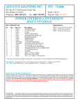
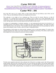
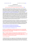
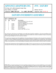
1
ADVANCE ADAPTERS INC.
P/N: 716805
P.O. Box 247, 4320 Aerotech Center Way
Paso Robles, CA 93447
Telephone: (800) 350-2223
Fax: (805) 238-4201
PAGE 1 OF 10
Page Rev. Date: 11-04-15
MANUAL STEERING CONVERSION
JEEP UNIVERSAL
KIT CONSISTS OF:
No.
Qty Part No.
Description
1.
2.
3.
4.
5.
6.
7.
8.
9.
10.
11.
12.
13.
14.
15.
16.
17.
18.
19.
20.
COLUMN BUSHING
CLAMP (Tie Rod)
CLAMP (Spud Shaft)
PITMAN ARM-MANUAL
MOUNTING PLATE
FRAME ENCLOSURE
MOUNTING PLATE
SHORT TIE ROD
LONG TIE ROD
GUSSET
SPUD SHAFT
7/8" UNIVERSAL/FLAMING RIVER
STEERING-UNIVERSAL JOINT 1"DD X 1"DD
STEERING SHAFT-36" COLLAPSIBLE W/O U-JOINT
5/16" FLAT WASHERS
3/8" NYLOCK NUT
WASHER
3/8"-16 x 2" BOLT
HIGH COLLAR WASHER
7/16" x 1-1/2" GRD. 8 / 12 PT. BOLTS
1
4
1
1
1
2
1
1
1
1
1
1
1
1
2
1
1
1
3
3
716810
716812
716814
716816
716823
716824
716826-BLK
716829
716830
716832
716834-30B
716847
716841
716863
723122
723703
723704
723725
724324
724347
**Kit does not include the Saginaw Steering Box, Steering Hoses or New Tie Rod Ends for Military Replacement.
May of 2013 Advance Adapters started updating its steering spud shafts to a male double D design. If you have a steering box
that requires the 36 tooth steering spud shaft you will need P/N 716834-36 instead of 716834-30.
P/N 716834-30 - Spud shaft .730” dia. x 30T (manual & power) (male side is 1" double D as of 5/24/13)
P/N 716834-36 - Spud shaft .730” dia. x 36T (manual) (male side is 1" double D as of 5/24/13)
Due to limited supplies of the center socket tie rod end P/N 716819 no longer is supplied in this kit.
JEEP SAGINAW STEERING INSTRUCTIONS:
Advance Adapters, Inc. has been manufacturing steering conversion parts for installation of the Saginaw steering boxes into Jeep
vehicles for more than twenty years. The parts we furnish are of the highest quality available and we utilize only proven design
components for our kits. Before you consider the conversion, we recommend that you thoroughly read and understand the complete
procedure. Do not take short cuts on steering installations. We recommend that these conversions be installed by a qualified
technician. Do not overlook any details. Remember that the control of your vehicle depends on the steering gear performance.
Failure of your steering system can result in severe damage and possibly injury.
SPECIAL NOTE:
The components packaged in this kit have been assembled and machined for specific type of conversions. Modifications to any of the components will void
any possible warranty or return privileges. If you do not fully understand modifications or changes that will be required to complete your conversion, we strongly recommend that
you contact our sales department for more information. This instruction sheet is only to be used for the assembly of Advance Adapter components. We recommend that a service
manual pertaining to your vehicle be obtained for specific torque values, wiring diagrams and other related equipment. These manuals are normally available at automotive dealerships
and parts stores.
ADVANCE ADAPTERS INC.
P/N: 716805
P.O. Box 247, 4320 Aerotech Center Way
Paso Robles, CA 93447
Telephone: (800) 350-2223
Fax: (805) 238-4201
PAGE 2 OF 10
Page Rev. Date: 08-05-10
MANUAL STEERING CONVERSION
JEEP UNIVERSAL
The Saginaw steering conversions for these vehicles is a proven advantage simply because they allow you to have better control
of your vehicle both on and off the highway. The problem with stock steering on these vehicles is excessive play or backlash. In
addition to offering a sound positive means of controlling your vehicle, it can be performed at a reasonable cost. Additional advantages
include exhaust clearance, engine positioning, and custom steering columns. These kits fit Jeep vehicles only.
Before you consider this conversion we recommend that you thoroughly read and understand the complete installation procedure.
Do not take shortcuts on steering installations. We recommend that these conversions be installed by a qualified technician.
The control of your vehicle depends on your steering performance. Failure of your steering system can result in severe damage
and possible injury.
Most Jeep vehicles had basically the same stock configuration. It is simply a gear box at the base of the steering column which controls
a drag link towards the front of the vehicle. The bellcrank is mounted on the front crossmember or axle and uses a push-pull affect
for steering. Because there are many motions and joints on this system, excessive free play and backlash develops.
Stock Illustration
Stock with long tie rod
The Saginaw steering system requires the elimination of the stock gear box and bellcrank. The new steering box is mounted on
the inside of the left front frame rail, just behind the bumper. Although this sounds simple, there are several things that must be
considered before the installation can be completed. Such things include:
Power or manual steering
Motor mount clearance on steering shaft
Steering column type
Tie rod size & length
Steering box location
Winch clearance
On engine conversions that are retaining the original steering box location, you will be locating the engine position as close as
possible to the original steering box. When eliminating the original
steering box, you will be able to offset the new engine 1” towards the
driver’s side in order to allow for additional front driveshaft and starter
motor clearance. In 1971, Jeep changed their steering design to
almost the exact same configuration as the kit that we offer. The
difference between the original Jeep installation and our installation
is mainly in the design of the mounting bracket for the steering box.
Jeep also used a rag joint coupler between the steering box and
Saginaw Steering Installation
steering shaft.
MANUAL BOX SELECTION:
Make sure the box that you select has the same basic configuration as the ones illustrated. Manual boxes can be found in the 1960s
and early 1970 GM cars, or Jeep vehicles 1972 & newer. The manual steering box must have a shaft stickout length of approximately
3” long, and the spline on the shaft approximately 1” long.
The location of the Saginaw steering box will require a spud shaft. This shaft couples and extends
the steering box shaft into the engine compartment. Manual boxes have two spline sizes that mate
to our spud shaft. Our manual steering kits are supplied with a .730” dia. 30 spline spud shaft. If your
steering box has .730” dia. 36 spline, Part No. 716834-36 can be substituted.
Manual Steering Box
SPECIAL NOTE:
The components packaged in this kit have been assembled and machined for specific type of conversions. Modifications to any of the components
will void any possible warranty or return privileges. If you do not fully understand modifications or changes that will be required to complete your conversion, we strongly
recommend that you contact our sales department for more information. This instruction sheet is only to be used for the assembly of Advance Adapter components.
We recommend that a service manual pertaining to your vehicle be obtained for specific torque values, wiring diagrams and other related equipment. These manuals
are normally available at automotive dealerships and parts stores.
ADVANCE ADAPTERS INC.
P/N: 716805
P.O. Box 247, 4320 Aerotech Center Way
Paso Robles, CA 93447
Telephone: (800) 350-2223
Fax: (805) 238-4201
PAGE 3 OF 10
Page Rev. Date: 08-05-10
MANUAL STEERING CONVERSION
JEEP UNIVERSAL
STEERING COLUMNS:
The stock steering column is the easiest option when installing the Saginaw steering. If you are planning to use a custom steering
column, some fabrication will be necessary for mounting.
The stock steering column protrudes through the firewall and into the engine compartment where it enters the stock Jeep worm
gear steering mechanism. The steering box must be disassembled so that the worm portion of the steering column shaft can be
cut off. Once removed, the end of the shaft must be machined to fit the universal joint provided. The diameter of this shaft must
be machined to fit a 7/8” (.875”) universal joint.
After the shaft has been machined, the column can be reassembled with the modified shaft. To support the shaft in the center of
the column, a bushing (P/N 716810) fits into the column housing with a precision fit on the shaft. Make sure the bushing and
the shaft have sufficient clearance for easy turning. The column will then need to be assembled into the support plate. The new
steering shaft bushing must be installed into the bottom of the steering column so that alignment and support of the shaft is
maintained.
With the bushing in place, you can now install the universal yoke. Slip the yoke in position onto the shaft and firmly up against the
bushing. Before tightening the set screw, have someone push the steering wheel downward. You will find that the column has
a slight spring tension. Make sure that the tension will provide a slight pressure of the universal yoke against the bushing. We require
the universal yoke installation to have a spot drilled in line with the set screw. Failure to make each yoke installation as specified
could result in the loss of control of the vehicle.
SPECIAL NOTE:
The components packaged in this kit have been assembled and machined for specific type of conversions. Modifications to any of the components
will void any possible warranty or return privileges. If you do not fully understand modifications or changes that will be required to complete your conversion, we strongly
recommend that you contact our sales department for more information. This instruction sheet is only to be used for the assembly of Advance Adapter components.
We recommend that a service manual pertaining to your vehicle be obtained for specific torque values, wiring diagrams and other related equipment. These manuals
are normally available at automotive dealerships and parts stores.
ADVANCE ADAPTERS INC.
P/N: 716805
P.O. Box 247, 4320 Aerotech Center Way
Paso Robles, CA 93447
Telephone: (800) 350-2223
Fax: (805) 238-4201
PAGE 4 OF 10
Page Rev. Date: 08-05-10
MANUAL STEERING CONVERSION
JEEP UNIVERSAL
DOUBLE SET SCREW WITH LOCTITE
& SAFETY WIRE
MOUNTING PLATE #716823
BUSHING #716810
WELD CLAMP TO MOUNTING PLATE
UNIVERSAL YOKE #716847
7/8" JEEP SHAFT
NOTE:
The stock Jeep column shaft is a 7/8" diameter.
This column shaft is also hallow. To properly
secure the yoke to the column, you will need to
use the yoke as a template and drill one 5/16"
diameter hole 3/16" deep for the short set
screw. The second hole for the long set screw
needs to be drilled with a 19/64" drill through
one side of the column shaft. This set screw is
then installed through the yoke and one side of
the column shaft tighten up on the opposite
inside wall of the stock column. Once both set
screws are installed tighten the jam nut and
locktite to secure.
STOCK JEEP COLUMN
ORIGINAL COLUMN CLAMP
CUSTOM STEERING COLUMNS:
Custom columns offer several distinct advantages. The advantages include locks, tilts, flashers, and custom vehicle appearance.
However, they do create some problems and require careful consideration when mounting them to the floorboard and universal joint
connection.
Universal joints are available to match nearly every style steering column available. The special spline size on some of the custom
columns will require a new U-joint. We offer a wide selection of various sizes. The new universal joint is supplied with a mating
connection that will fit the new 3/4” DD steering shaft. If a custom column is being used and you have already purchased the stock
Jeep 7/8” diameter column yoke, you will then need to exchange your universal joint for the one that will be required on your installation.
We offer special yoke assemblies to connect a custom steering column to our Saginaw steering components.
P/N 716848 P/N 716849 P/N 716850 -
1” 48 spline Universal yoke (GM columns)
1” DD x 3/4” DD Universal yoke (GM and Ford)
3/4” x 36 spline Universal yoke (GM and Ford)
(The dimensions represent the column side of these yokes only. The opposite side of these yokes is a 3/4” DD)
SPECIAL NOTE:
The components packaged in this kit have been assembled and machined for specific type of conversions. Modifications to any of the components
will void any possible warranty or return privileges. If you do not fully understand modifications or changes that will be required to complete your conversion, we strongly
recommend that you contact our sales department for more information. This instruction sheet is only to be used for the assembly of Advance Adapter components.
We recommend that a service manual pertaining to your vehicle be obtained for specific torque values, wiring diagrams and other related equipment. These manuals
are normally available at automotive dealerships and parts stores.
ADVANCE ADAPTERS INC.
P/N: 716805
P.O. Box 247, 4320 Aerotech Center Way
Paso Robles, CA 93447
Telephone: (800) 350-2223
Fax: (805) 238-4201
PAGE 5 OF 10
Page Rev. Date: 07-09-13
MANUAL STEERING CONVERSION
JEEP UNIVERSAL
STEERING SHAFT:
The control shaft between the end of the column and the steering box spud shaft is defined as the steering shaft.
With each kit, we have provided a 3/4” DD X 1"DD shaft that has a length of 36”. The shaft can be shortened to the necessary
length for your installation. The new shaft assembly has a 3/4” DD end that will need to fit into the steering column universal
joint. Use the same procedure to spot drill both of the set screws, and Loctite the connections with the two lock nuts. The lower
connection Use the same procedure to spot drill both of the set screws, and Loctite the connections with the two lock nuts.
Always use Loctite on the double set screws and lock nuts for all universal yoke connections. P/N 716863
P/N 716841 - Universal Joint (1" DD X 1" DD)
P/N 716844 - Universal Joint 3/4”DD X .800 36 Spline
P/N 716847 - Jeep column shaft 3/4” DD x 7/8”
P/N 716853 - Universal Joint 3/4” DD x 3/4” - 30
P/N 716843 - Universal Joint 1” DD X 7/8”
P/N 716845 - Universal Joint 1” DD X .3/4 - 36 Spline
P/N 716846 - Universal Joint 1” DD X .800 36 Spline
P/N 716854 - Universal Joint 1” DD X 3/4” - 30
ROUTING THE STEERING SHAFT:
Routing the steering driveshaft may seem simple, but care should be taken as to the actual routing.
On some Jeep installations, it may be necessary to go directly through the motor mount. Routes may
be adjusted by changing the angle of the steering box slightly, or by extending the universal yoke from
the column bushing with a spacer. Before any final route is decided, be sure to allow for suspension
travel and engine movement. On some conversions, a third universal yoke might be considered along
with a bearing pillow block.
Manifold clearance on Jeeps with a stock 225 V6. The steering shaft can have some exhaust clearance
issues on some Jeeps. One that was brought to our attention is the Jeep 225 V6 with a Sawinaw steering
swap. The steering shaft hits the stock manifold, two options for clearance would be switch to exhaust
headers for the Jeep or switch to a Buick 231 1975 and newer rear wheel drive vehicle manifold.
SPECIAL NOTE:
The components packaged in this kit have been assembled and machined for specific type of conversions. Modifications to any of the components
will void any possible warranty or return privileges. If you do not fully understand modifications or changes that will be required to complete your conversion, we strongly
recommend that you contact our sales department for more information. This instruction sheet is only to be used for the assembly of Advance Adapter components.
We recommend that a service manual pertaining to your vehicle be obtained for specific torque values, wiring diagrams and other related equipment. These manuals
are normally available at automotive dealerships and parts stores.
ADVANCE ADAPTERS INC.
P/N: 7716805
P.O. Box 247, 4320 Aerotech Center Way
Paso Robles, CA 93447
Telephone: (800) 350-2223
Fax: (805) 238-4201
PAGE 6 OF 10
Page Rev. Date: 08-05-10
MANUAL STEERING CONVERSION
JEEP UNIVERSAL
FRONT CROSSMEMBER:
The early Jeeps used a bell crank mounted on the front crossmember, and this crossmember
was originally located in the engine compartment. If an engine swap has been performed, we
recommend installing a new crossmember located further forward, directly in line with the front
grill. When installing the Saginaw conversion, this new crossmember will require an access
hole that is roughly 2-1/2” in diameter to provide clearance for the steering spud shaft clamp.
This access hole allows the steering spud shaft to extend through and into the engine
compartment. In most cases, the front crossmember must be reinforced on both the top &
bottom because of the diameter of the access hole.
STEERING BOX LOCATION:
The actual positioning of the steering box should be accomplished by bolting the box to the plate provided, and then temporarily
clamping the plate and box to the inner frame rail until an ideal position is achieved. Make sure this position allows the steering
spud shaft to extend through the front crossmember and into the engine compartment. Once in position, the plate must be completely
welded to the frame. Since this plate encounters extreme forces from the steering system, the welding of this plate should be done
by a certified welder.
We have provided a pair of 3/16” thick steel frame enclosures to box in both of your frame rails, providing a good base for welding
the steering box mounting plate. The steering box mounting plate must have a solid surface for welding and positioning. The extra
plate is simply supplied for boxing of the passenger side frame rail. On vehicles equipped with winches, it may be necessary to
offset the winch bumper to allow for the steering box clearance.
When using mounting plate, P/N 716826 you will be required to have this plate welded onto your frame rail. This plate is made
of steel so that a good weld can be made. These welds should be made only by a qualified welder. Do not short change your
installation with a poor quality weld of these mounting plates to your frame rail. The plates should be welded along the complete
perimeter. We have included a special frame-to-steering mounting plate gusset, P/N 716832, to provide additional support from
the outside of your frame rail to the bottom of the steering box mounting plate.
power steering plate shown in this photo
SPECIAL NOTE:
The components packaged in this kit have been assembled and machined for specific type of conversions. Modifications to any of the components
will void any possible warranty or return privileges. If you do not fully understand modifications or changes that will be required to complete your conversion, we strongly
recommend that you contact our sales department for more information. This instruction sheet is only to be used for the assembly of Advance Adapter components.
We recommend that a service manual pertaining to your vehicle be obtained for specific torque values, wiring diagrams and other related equipment. These manuals
are normally available at automotive dealerships and parts stores.
ADVANCE ADAPTERS INC.
P/N: 716805
P.O. Box 247, 4320 Aerotech Center Way
Paso Robles, CA 93447
Telephone: (800) 350-2223
Fax: (805) 238-4201
PAGE 7 OF 10
Page Rev. Date: 08-05-10
MANUAL STEERING CONVERSION
JEEP UNIVERSAL
SAGINAW STEERING BOXES:
Power and Manual steering gear boxes are very similar. We have already illustrated what the box should look like. The steering
box must be able to mount on the inside frame rail of your vehicle, with the input shaft extending horizontally toward the firewall. This
input shaft is normally not long enough to extend fully into the engine compartment to couple with the steering driveshaft. This is
why we offer steering spud shafts to extend these steering input shafts.
The manual boxes have variable input shaft lengths. The manual boxes that we recommend have an input shaft extending
approximately three to four inches away from the main housing. The manual steering boxes must be secured with a minimum of
three socket head cap screws with high collar lock washers. The threads in the manual steering box must be drilled out for clearance
of the 7/16" socket head cap screws so that the bolts can be installed through the steering box into the mounting plate.
TIE RODS:
Each of our kits include the necessary long & short tie rods for your conversion. The long tie rod connects the two front wheels,
while the other connects the Pitman arm to the passenger side steering knuckle/center socket tie rod. Both tie rods are
manufactured with both a right & left hand thread to assist in proper alignment. The Pitman arm that we have furnished with your
kit has exactly the same taper that the Jeep tie rod ends have. Care should be taken for the proper fit of the tie rod end’s taper
and threads when installing into the Pitman arm. In some cases, it may be necessary to use two or three washers on the top
side of the Pitman Arm so that the threads on the tie rod end will secure the proper taper fit. All tie rod ends must be secured with
a castle nut and cotter pin. All tie rod-to-tie rod end connections must have a tie rod clamp installed with a bolt, lock washer, and
nut. We DO NOT find it acceptable to cut and weld the tie rods.
PITMAN ARMS:
The steering box Pitman arms vary from power to manual, and are not interchangeable. The Pitman arm supplied in each kit
is for use on vehicles that are not equipped with a suspension lift. If your vehicle requires a dropped Pitman Arm, then
we suggest that you contact a suspension lift company. We DO NOT find it acceptable to cut or bend our Pitman Arms.
POWER STEERING PUMPS:
There are only a few pumps available and most are interchangeable. We recommend the purchase of the power steering pump
and steering box as a pair if possible. For proper installation, we recommend the hose kits from PSC. The hardware for mounting
the pump to the engine can be standard parts from Chevy & Ford engines.
TURNING ANGLE ADJUSTMENT:
To avoid damage to the outer axle U-joints, it is advisable that you check the turning angle. The following is a list of the correct turning
angles.
CJ2A, CJ3A
CJ3B
CJ3B
23 Degrees
Up to Serial No. 57348-35326, 23 Degrees
After Serial No. 57348-35326, 27.5 Degrees
CJ5
CJ5
CJ6
CJ6
Up to Serial No. 57548-48284, 23 Degrees
After Serial No. 57548-48284, 27.5 Degrees
Up to Serial No. 57748-12497, 23 Degrees
After Serial No. 57748-12497, 27.5 Degrees
To adjust the turning angle stops, loosen the lock nut and turn the adjustment screw. On some early models, a secured weld will
have to be broken. The adjusting screw is located on the axle tube near the knuckle housing. For further detailed information, refer
to your vehicle service manual.
SPECIAL NOTE:
The components packaged in this kit have been assembled and machined for specific type of conversions. Modifications to any of the components
will void any possible warranty or return privileges. If you do not fully understand modifications or changes that will be required to complete your conversion, we strongly
recommend that you contact our sales department for more information. This instruction sheet is only to be used for the assembly of Advance Adapter components.
We recommend that a service manual pertaining to your vehicle be obtained for specific torque values, wiring diagrams and other related equipment. These manuals
are normally available at automotive dealerships and parts stores.
ADVANCE ADAPTERS INC.
P/N: 716805
P.O. Box 247, 4320 Aerotech Center Way
Paso Robles, CA 93447
Telephone: (800) 350-2223
Fax: (805) 238-4201
PAGE 8 OF 10
Page Rev. Date: 08-05-10
MANUAL STEERING CONVERSION
JEEP UNIVERSAL
CASTER ADJUSTMENT:
The purpose of the caster adjustment is to provide steering stability, which will keep the front wheels in a straight ahead position.
It also assists in straightening the wheels after making a turn. If the angle of the caster is found to be incorrect, correct it to the
specifications given in your service manual. The correct angle is obtained by installing caster shims between the axle pad and the
springs. If the camber and the toe-in are correct and it is known that the axle is not twisted, a check may be made by testing the vehicle
on the road. Before road testing, make sure that the tires are properly inflated at the same pressure. If the vehicle turns easy to
either side, but is hard to straighten out, insufficient caster for ease of handling is indicated. If correction is necessary, it can be
accomplished by changing the shims between the spring and axle pads.
TOE-IN ADJUSTMENT:
Lift the front of the vehicle to raise the front tires off of the ground. Turn the wheels to the straight ahead position. Using a pencil
or chalk, scribe a line in the center of each tire tread. The mark should circle the entire diameter of the tire. Measure the distance
between the scribe lines at the front and rear of the wheels, using care that both measurements are made at an equal distance
from the floor level. The distance between the lines should be greater at the rear then at the front by 3/64" to 3/32”. To adjust, loosen
the clamp bolts and turn the long tie rod with a small pipe wrench. The tie rod is threaded with right hand and left hand threads to
provide equal adjustment at both wheels. Do not overlook the retightening of the two clamp bolts. It is a common practice to measure
between the wheel rims. This is satisfactory providing the wheels run true. By scribing a line on the tire thread, a measurement
is taken between the road contact points reducing error caused by wheel rim run out.
It is recommended to have the alignment done by a qualified technician.
SPECIAL NOTE:
The components packaged in this kit have been assembled and machined for specific type of conversions. Modifications to any of the components
will void any possible warranty or return privileges. If you do not fully understand modifications or changes that will be required to complete your conversion, we strongly
recommend that you contact our sales department for more information. This instruction sheet is only to be used for the assembly of Advance Adapter components.
We recommend that a service manual pertaining to your vehicle be obtained for specific torque values, wiring diagrams and other related equipment. These manuals
are normally available at automotive dealerships and parts stores.
ADVANCE ADAPTERS INC.
P/N: 716805
P.O. Box 247, 4320 Aerotech Center Way
Paso Robles, CA 93447
Telephone: (800) 350-2223
Fax: (805) 238-4201
PAGE 9 OF 10
Page Rev. Date: 08-05-10
MANUAL STEERING CONVERSION
JEEP UNIVERSAL
FRAME RAIL
MOUNTING PLATE
Part No. 716826
Part No. 716834
FRAME ENCLOSURES
Part No. 716824
GUSSET
Part No. 716832
MANUAL STEERING BOX
Stock Jeep or our
Part No. 716821
LONG TIE ROD
Part No. 716830
PITMAN ARM
Part No. 716816
PITMAN ARM
LOCKWASHER & NUT
Stock Jeep or our
Part No. 716821
CENTER SOCKET TIE ROD END
Part No. 716819 (Left hand thread)
SHORT TIE ROD
Part No. 716829
STOCK CLAMPS
Stock Jeep or our
Part No. 716820
SPECIAL NOTE:
The components packaged in this kit have been assembled and machined for specific type of conversions. Modifications to any of the components will void
any possible warranty or return privileges. If you do not fully understand modifications or changes that will be required to complete your conversion, we strongly recommend that
you contact our sales department for more information. This instruction sheet is only to be used for the assembly of Advance Adapter components. We recommend that a service
manual pertaining to your vehicle be obtained for specific torque values, wiring diagrams and other related equipment. These manuals are normally available at automotive dealerships
and parts stores.
ADVANCE ADAPTERS INC.
P/N: 716805
P.O. Box 247, 4320 Aerotech Center Way
Paso Robles, CA 93447
Telephone: (800) 350-2223
Fax: (805) 238-4201
PAGE 10 OF 10
Page Rev. Date: 07-09-13
MANUAL STEERING CONVERSION
JEEP UNIVERSAL
Installation Tips
We recommend Weldless DD and Double Splined universal joints for the best steering system.
Weldless DD universal joint features two set screws for maximum holding power. Position yoke, tighten set screws to mark the shaft.
Remove yoke and drill the set point on the shaft. When installing the universal joint, set screws are tightened into the countersink
mark, then tighten the jam nut and the shaft will not move. We recommend the use of Loctite.
Spline both ends (3/4"-36) universal joint is the preferred design, as it allows the shaft to be rotated in small increments during
installation to properly align or phase the steering system. Once the steering is set, tighten set screws to mark the shaft. Remove
yoke and drill the set point on the shaft. When installing the universal joint, set screws are tightened into the countersink mark, then
tighten the jam nut and the shaft will not move. We recommend the use of Loctite.
Optional Equipment
716863 - Collapsible Steering Shaft 3/4" DD X 1" DD
(comes without any universal joints)
716841 - Universal Joint (1" DD X 1" DD)
716843 - Universal Joint (1" DD X 7/8")
716844 - Universal Joint (3/4" DD X .800" 36 spline)
716845 - Universal Joint (1" DD X 3/4" 36 spline)
716846 - Universal Joint (1" DD X .800" 36 spline)
716848 - Universal Joint (3/4" DD X 1" 48 spline)
716849 - Universal Joint (3/4" DD X 1" DD)
716850 - Universal Joint (3/4" DD X 3/4" 36 spline)
716851 - Universal Joint (3/4" DD X 3/4" DD)
716852 - Universal Joint (3/4" 36 spline X 3/4" 36 Spline)
A FEW NOTES
**Phasing-Keep the forks of the yokes closest to each other in line and parallel to the centerline of the shaft to avoid binding.
**Always use the minimum angle when designing your system - ideally 10 degrees or less, NEVER MORE THAN 35 DEGREES.
**NEVER WELD a universal joint.
Welding reduces the strength of the metal and can melt the needle bearing seal.
**BUFFING creates a very attractive finish in a matter of minutes.
It is very important not to buff the caps because over heating
may damage the bearing seals.
SPECIAL NOTE:
The components packaged in this kit have been assembled and machined for specific type of conversions. Modifications to any of the components will void
any possible warranty or return privileges. If you do not fully understand modifications or changes that will be required to complete your conversion, we strongly recommend that
you contact our sales department for more information. This instruction sheet is only to be used for the assembly of Advance Adapter components. We recommend that a service
manual pertaining to your vehicle be obtained for specific torque values, wiring diagrams and other related equipment. These manuals are normally available at automotive dealerships
and parts stores.