1
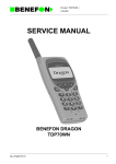
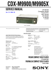
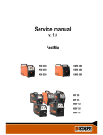
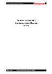
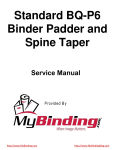
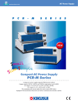
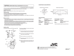
ECM-S80
SERVICE MANUAL
US Model
Canadian Model
AEP Model
E Model
Ver 1.0 2002. 02
SPECIFICATIONS
Type
Cord
Electret condenser microphone
ø 2.2 mm (3 /32 in.)OFC litz cord
(2 core shielded)
Length:Approx.70 cm (27 5 /8 in.)
Attached with gold plated L-shaped stereo
miniplug
Power source 2 way power supply system
plug-in power
alkaline manganese battery LR44 (1)
Dimensions
Approx.54 × 11 × 86 mm (w/h/d)
(2 1 /4 × 7 /16 × 3 1 /2 in.)
Mass
Approx.39 g (1 oz.)(including battery)
Frequently response
100 – 10,000 Hz
Directivity
Unidirectional × 2
Output impedance
1.6 k Ω ± 30%
Sensitivity
Open circuit output voltage level –40 ± 4 dB/Pa
0 dB =1 V /Pa,1,000 Hz
(1 Pa =10 µ bar =94 dBSPL)
Battery life
Approx.80 hours (continuous operation)
Operating temperature range
0 °C – 40 °C (32 °F – 104 °F)
Design and specifications are subject to change without notice.
ELECTRET CONDENSER MICROPHONE
9-873-538-01
Sony Corporation
2002B0200-1
© 2002.2
Personal Audio Company
Published by Sony Engineering Corporation
ECM-S80
SECTION 1
SERVICING NOTES
Notes on chip component replacement
• Never reuse a disconnected chip component.
• Notice that the minus side of a tantalum capacitor may be damaged by heat.
z
UNLEADED SOLDER
Boards requiring use of unleaded solder are printed with the
lead-free mark (LF) indicating the solder contains no lead.
(Caution: Some printed circuit boards may not come printed
with the lead free mark due to their particular size.)
“REEL ASSY, CORD” INSTALLATION
1 Put the flexible board through the hole of the flexible holder.
2 Wind flexible board around the flexible holder.
Note : Leave the flexible board for 20 to 30mm.
3 Attach the flexible holder to the "reel ASSY, cord".
4 Loosen flexible board doesn't seem to coil around the flexible holder.
Flexible board
1
: LEAD FREE MARK
Holder, flexible
Unleaded solder has the following characteristics.
• Unleaded solder melts at a temperature about 40°C higher
than ordinary solder.
Ordinary soldering irons can be used but the iron tip has to
be applied to the solder joint for a slightly longer time.
Soldering irons using a temperature regulator should be set
to about 350°C.
Caution: The printed pattern (copper foil) may peel away if
the heated tip is applied for too long, so be careful!
• Strong viscosity
Unleaded solder is more viscous (sticky, less prone to
flow) than ordinary solder so use caution not to let solder
bridges occur such as on IC pins, etc.
• Usable with ordinary solder
It is best to use only unleaded solder but unleaded solder
may also be added to ordinary solder.
Flexible board
20 to 30 mm
Holder, flexible
2
Connection cord
3
4 Loosen flexible board
doesn't seem to coil
around the flexible holder.
Reel ASSY, cord
Knot part of connection cord
SECTION 2
GENERAL
This section is extracted from
instruction manual.
LOCATING THE CONTROLS
5
1
2
3
6
4
2
1 Cord retracting wheel
2 POWER switch
When the microphone is powered by plug-in power,turn its
own power off.
3 Battery check indicator
4 Microphone
5 Stereo miniplug
To the microphone jack of the recording equipment
6 Slide
SECTION 3
DIAGRAMS
ECM-S80
: Uses unleaded solder.
3-1. PRINTED WIRING BOARD
3
2
1
4
5
C4
BLK
RED
MIC1
L
R5
R2
C5
B
R6
D3
POWER
1-682-765SW1,2
POWER
OFFTON
(PLUG IN POWER)
P1
(OUTPUT)
BLK
C6
R7
BLK
SW2
R1
D2
C3
RED
SW1
D1
RED
AMP BOARD
A
11
(11)
ALKALINE MANGANESE BATTERY
LR44
1PC, 1.5V
MIC2
R
Note:
• X : parts extracted from the component side.
• b : Pattern from the side which enables seeing.
3
ECM-S80
3-2. SCHEMATIC DIAGRAM
MIC1
D1
UDZSTE-17-4.7B
C3
1
L
SW1
MIC2
D2
UDZSTE-17-4.7B
R1
3.3k
P1
(OUTPUT)
C4
1
R2
3.3k
R
SW1,2
C5
47
2.5V
R7
100
ON
OFF
POWER
(PLUG IN POWER)
SW2
R5
10k
ALKALINE MANGANESE BATTERY
LR44
C6
47
2.5V
R6
470
D3
SML-310LT
POWER
1PC,1.5V
Note:
• All capacitors are in µF unless otherwise noted. pF: µµF 50 WV or
less are not indicated except for electrolytics and tantalums.
• All resistors are in Ω and 1/4 W or less unless otherwise specified.
• A : B+ Line.
• Voltages are dc with respect to ground under no-signal conditions.
• Voltages are taken with a VOM (Input impedance 10 MΩ).
Voltage variations may be noted due to normal production tolerances.
• Signal path.
F
4
ECM-S80
SECTION 4
EXPLODED VIEW
NOTE :
• -XX, -X mean standardized parts, so they
may have some difference from the original
one.
• Items marked “ * ”are not stocked since they
are seldom required for routine service. Some
delay should be anticipated when ordering
these items.
• The mechanical parts with no reference
number in the exploded views are not
supplied.
15
14
16
18
17
23
12
19
13
11
20
10
P1
9
22
21
8
1
7
1
6
2
3
1
2
5
1
4
2
Ref. No.
Part No.
Description
1
2
3
4
5
3-234-433-01
3-318-203-01
3-234-420-01
3-234-425-01
3-234-430-02
FOOT, RUBBER
SCREW (B 1.7X6), TAPPING
TERMINAL, PLUS
CASE, BATTERY
SLEEVE
6
7
8
9
10
3-234-418-01
3-234-421-01
3-234-427-01
3-234-434-01
3-234-431-01
CASE, REAR
TERMINAL, MINUS
SLIDE, CORD
RING, SLIP
HOLDER, FLEXIBLE
11
12
A-3174-083-A REEL ASSY, CORD
3-234-422-01 LEVER, SWITCH
Remark
Ref. No.
13
14
15
Part No.
Description
Remark
3-234-424-01 SPRING, LOCK
A-3174-081-A CASE ASSY, FRONT
3-234-423-01 KNOB, SWITCH
16
* 17
18
19
20
1-682-766-11
1-682-765-11
3-318-203-34
3-237-418-01
A-3174-087-A
FLEXIBLE BOARD
AMPLIFIER BOARD
SCREW (B1.7X2.5), TAPPING
SPRING, GROUND COIL
UNIT ASSY (MIC L, R)
21
22
23
P1
3-237-422-01
3-238-572-01
3-237-420-01
1-823-289-11
CUSHION
PLATE, GROUND
SHEET (E), DOUBLE-FACE ADHESIVE
CORD, CONNECTION (2 CORE) (OUTPUT)
5
ECM-S80
SECTION 5
ELECTRICAL PARTS LIST
AMPLIFIER
Ref.
No.
Note:
Part No.
Description
When indicating parts by reference
number, please include the board
name.
Ref. No.
Part No.
Remarks
C3
C4
C5
C6
1-125-837-11
1-125-837-11
1-119-663-11
1-119-663-11
Description
CERAMIC CHIP
CERAMIC CHIP
TANTAL. CHIP
TANTAL. CHIP
Remarks
1uF
1uF
47uF
47uF
10%
10%
20%
20%
6.3V
6.3V
2.5V
2.5V
1-216-827-11
1-216-827-11
1-216-833-11
1-216-817-11
1-216-809-11
METAL CHIP
METAL CHIP
METAL CHIP
METAL CHIP
METAL CHIP
3.3K
3.3K
10K
470
100
5%
5%
5%
5%
5%
1/16W
1/16W
1/16W
1/16W
1/16W
<SWITCH>
SW1
1-572-018-11 SWITCH, SLIDE (POWER)
SW2
1-572-018-31 SWITCH, SLIDE (POWER)
***********************************************************
6
Part No.
Remarks
Description
Remarks
16
1-682-766-11 FLEXIBLE BOARD
20
A-3174-087-A UNIT ASSY (MIC L, R)
P1
1-823-289-11 CORD, CONNECTION (2 CORE) (OUTPUT)
***********************************************************
ACCESSORIES
************
3-241-661-11 MANUAL, INSTRUCTION
(ENGLISH, FRENCH, GERMAN, SPANISH,
ITALIAN, PORTUGUESE)
8-719-083-60 DIODE UDZSTE-174.7B
8-719-083-60 DIODE UDZSTE-174.7B
8-719-074-30 DIODE CL-190UR-CD-T
<RESISTOR>
R1
R2
R5
R6
R7
Ref. No.
Description
• SEMICONDUCTORS
In each case, u: µ , for example:
uA...: µ A..., uPA...: µ PA..., uPB...: µ PB...,
uPC...: µ PC..., uPD...: µ PD...
• CAPACITORS
uF : µ F
• COILS
uH : µ H
MISCELLANEOUS
***************
<DIODE>
D1
D2
D3
Part No.
• Due to standardization, replacements in the parts
list may be different from the parts specified in the
diagrams or the components used on the set.
• -XX, -X mean standardized parts, so they may
have some difference from the original one.
• Items marked “*” are not stocked since they are
seldom required for routine service. Some delay
should be anticipated when ordering these items.
• RESISTORS
All resistors are in ohms
METAL: Metal-film resistor
METAL OXIDE: Metal Oxide-film resistor
F : nonflammable
1-682-765-11 AMPLIFIER BOARD
****************
<CAPASITOR>
*
Ref. No.
ECM-S80
Ref. No.
Part No.
Description
Remarks
Ref. No.
Part No.
Description
Remarks
7
ECM-S80
REVISION HISTORY
Clicking the version allows you to jump to the revised page.
Also, clicking the version at the upper right on the revised page allows you to jump to the next revised
page.
Ver.
Date
1.0
2002.02
Description of Revision
New