1
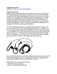
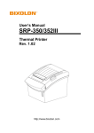
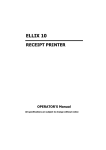
~ Kansaki KBW 10 Transmission Fluid Leak Repair ~
Replacing the oil seal, O ring and locking nut on Spináche
1989 Island Packet 35
Spring 2015
So, as with any "old" boat, just when you think you've fixed everything there is to be
fixed, Murphy throws a re-fix in your face.
Back in the spring of 2007, while preparing for my last Marion-Bermuda race, I
discovered transmission fluid leaking from the shaft couplings behind the transmission
block. A certified Yanmar service center told me it was the rear transmission seal that
had failed, so I had them fix it. Since a certified Yanmar mechanic will only fix this seal
by taking the entire transmission out of the boat and taking it to their shop (a big
production), it was a big expense, costing nearly $1,300. While they were in there, they
replaced some other stuff (the "damper disc"?) in the transmission because, as they
said, "This opportunity is never likely to arise again"! Murphy must have been listening.
This past summer, 7 years and 750 engine hours later, I discovered this.....
I'm sure by now the cost of this repair has jumped by 30- 50%. So, I did what any do-ityourselfer would have done. I went online to see if I could do it myself.
There I discovered several people who had done the repair without removing the
transmission, one in particular who did it on an Island Packet. Below is his photo of the
first step in this process: separating the couplings that connect the output shaft coming
out of the transmission to the prop shaft running out to the prop. There are 4 grade 8
bolts that hold these together....
To separate these couplings, you have to slide the prop shaft aft (far enough to slide
the output coupling off the output shaft). To accomplish this, you need to unthread the
stuffing box packing gland to relieve pressure on the prop shaft.
This is my stuffing box before unthreading....
...and after....
(note the water rushing in through the through-hull)
Then it was easy to slide the prop shaft aft.
This is how much room I had before hitting the rudder (more than enough)...
The prop shaft coupling now was moved aft through the bulkhead opening. Using
"smoke and mirrors", I could see the locking nut that holds the output coupling to the
shaft. Note the caulking dent, notched into the shaft key slot, that keeps the nut from
backing off in reverse. Notice also all the dried up greasy transmission fluid that has
accumulated inside the coupling and around the nut...
The diagram on the next page, from the Yanmar Service Manual, shows the parts of
the transmission we are dealing with in this repair.
1. the splined end of the output shaft (#1)
2. the groove that runs around the shaft just forward of the splines (the double line
just near where the #1 line meets the shaft in the drawing)
3. the outer roller bearing (#3 bottom left)
4. the O ring (#2),
5. the output coupling (#28)
6. the locking nut (#29)
Before dismantling the coupling, the transmission had to be drained of lubricating fluid.
Then the locking nut had to be removed. This would require enough torque to break
the caulking (dent) in the nut's lip. Due to the unique shape of this nut, it requires a
custom tool in order to be removed or tightened.
Yanmar sells the wrench shown below (part # 177099-09010) expressly for that
purpose...at a cost of about $235!...
Online I found this photo of a homemade wrench...
I showed the nut, and the photo of the homemade wrench, to my very handy brotherin-law, Jack Roberts (former owner of Packet Inn, a 1984
1994 IP31), while visiting him this
winter. He fashioned me a similar tool from an aluminum bar into which he drilled and
tapped 2 holes, then added some stainless steel bolts. He even added some "serial
numbers" just for authenticity! ...
The spacers under the bolt heads made it easy to adjust the length of the bolts so that
the handle lay as close to the coupling as possible when engaging the nut with the nut
fully threaded in, making the tool much stiffer when force was applied. On the next page is Jack's homemade tool in place, with the bolts inserted into the
notches on the nut. With a little force, I was able to break the caulking and unthread the
nut...it worked like a charm!
This is the output coupling removed, cleaned up and showing the splines. Note also
the impression along the inner edge of the forward end that accommodates the O ring
(arrow)...
This shows how the O ring fits against the forward end of the coupling... (later the O ring will actually be placed around the shaft and rolled forward to set in the
groove on the shaft)
Here is the shaft exiting the transmission housing after removing the coupling.
1.
2.
3.
4.
key slot - for caulking (denting) the lip of the locking nut once tightly threaded threads for the locking nut (right handed)
splines - integrate the coupling with the shaft
oil seal - prevents oil from leaking between the housing and the coupling
The next job was to remove the oil seal. This was popped out by leverage with a
closed pair of needle nosed pliers. I tried a can opener but that didn't work. A pick was
suggested, but I couldn't find mine.
The oil seal is a hard plastic ring that fits snuggly in the housing. It has 2 parallel
flexible lips on the inner side that seal against the coupling. In the middle is a spring
that encircles the flexible lips and keeps them pressed against the coupling. I
damaged the spring taking the seal out. Otherwise it appeared to be doing its job..
A failed oil seal was not my problem, because the oil was leaking along the shaft and
inside the couplings (not around them).
So my problem had to be the O ring.
Now, with the oil seal out of the way, I could see the O ring.
The arrow shows the position of the O ring where the roller bearing meets the shaft...
I picked the O ring out with a small flathead screwdriver and then cleaned the entire
area with WD-40, mineral spirits and finally 90% alcohol to remove all the transmission
oil. Then I could see the groove in the shaft that the O ring had been sitting in
(arrow).... The new O ring on the left and the damaged one on the right...
A piece I found floating around in there....
This cross section gives you an idea of the arrangement of these parts...
Now it was time to install the new parts: O ring, oil seal and locking nut (total: $33.64)
First was the O ring, placed over the shaft and rolled back until it set in the groove. Next was the oil seal:
The new oil seal as seen from the side that goes into the housing first...
The "outside" (aft) surface of the seal...
I placed the seal into the housing by hand to get it even, then tapped it carefully with a
hammer and a small block of teak, going all around advancing it evenly.
It was a tight fit but eventually sat flush with the housing...
Next I slid the coupling over the shaft and aligned the splines, sliding the coupling
forward until it sat inside the seal and up against the O ring. I placed some blue Loctite
on the threads of the nut and the shaft, then hand-threaded the nut in place with the
flange facing aft.
I then used Jackʼs custom tool to tighten the nut.
This is how the tool fit in the notches of the locking nut...
I tightened the nut with as much force as I felt equaled the 80 pounds of torque
recommended...
(the locking nut snug in place)
Next, using a heavy chisel and ball-peen hammer, I made a dent in the nut's flange
directly over the key notch in the end of the shaft, effectively "caulking" the nut in
place...
Next the packing gland was loosened to ease pressure on the prop shaft, so it could
be moved forward bringing the two couplings back together. Before bolting, this was a
good time to check the alignment of the two shafts by checking for an even gap all the
way around where the couplings meet. Mine was perfect...no adjustment needed. A
malaligned shaft is a common cause of many oil seal failures.
Keep in mind, most of this work was done looking through a mirror and cramped in the
tight space between the back of the engine and the bulkhead...a space of about 10".
There was no room to apply a socket wrench. I used combination wrenches to reattach
the couplings with the 4 bolts, lock washers and nuts.
Now it was ready to paint!
Next: refill the transmission with oil and start her up and see if she leaks...have to wait
for warmer weather.
Jim Lawless
s/v Spináche, IP35-016
March 2015