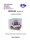
1
Instrumentation Scientifique de Laboratoire
ISL HOUILLON VISCOMETER BATH
INSTALLATION, OPERATION
AND
SERVICE
MANUAL
Standard Methods
ASTM D2270, ASTM D445, ASTM D341, ISO 3104, IP 71
DIN 51550, NF T60-100
Instrumentation Scientifique de Laboratoire - BP 70285 - 14653 CARPIQUET CEDEX FRANCE
Tél : (+33) 2.31.26.43.00
Fax : (+33) 2.31.26.62.93
Web: www.isl-france.com
Page 2
DOCV066A001-M
ISL
Revision Tracking
Revision
index
A
B
§ concerned
Modification descriptive
Date
3
Original Issue
File format
89/01
90/04
92/09
93/07
93/10
95/11
96/11
97/08
99/04
C
D
E
F
G
H
I
J
2.4.1
Appendix I
K
L
M
DOCV066A001-M
2.2.3
§1.1
§ 1.1.3
§1.1.3
§ 3.1.3
V5.5 configuration
Revision
Robot interface option
VH2 version
Operator alarm
Complete revision
Setpoint values modification
Solvent tank 1 et 2 location
Spare parts list update
Original issue of the file DOCV066X200 : Spare parts list
Update
Install drainage pipes
Printer using under Windows XP
Temperature range of the Houillon Viscometer
Temperature range of the Houillon Viscometer raised to 120°C
“Temperature Safety”: updating of the setting values
02/11
07/11/03
05/04/04
23/02/05
Page 3
ISL
ISL (C) copyright
The VH1 and VH2 Analyzers and this manual are protected by copyright.
Reproduction of the unit will result in prosecution.
All rights to the manual are reserved. Reproduction in any form, including in the form of excerpts, shall require written
permission from the copyright holder.
Houillon Viscometer Software(c) 1994, ISL
This software is owned by ISL and is registered under the registration number IDDN.FR.001.020002.00.R.P.1994.30000 at the
« Agence pour la Protection des Programmes » - 249, Avenue de Crimée - 75019 Paris. It is protected in France by the « Code de
Propriété Intellectuelle » laws and internationally by international treaty provisions, and all other applicable national laws. It
must not be copied, reproduced, adapted, translated, rented or disassembled. This also applies to the accompanying manuals.
INFORMATION
Information in this document is subject to change without notice and does not represent a commitment on the part of ISL. ISL
provides this document “as is”, without warranty of any kind, either expressed or implied, including, but not limited to, the
particular purpose. ISL may make improvements and/or changes in this manual or in the product(s) and/or the programme (s)
described in this manual at any time. This product could include technical inaccuracies or typographical errors. Changes are
periodically made to the information herein; these changes may be incorporated in new editions of the publication. Reproduction
of any part of this manual without express written permission is forbidden.
- AT, IBM are registered trademarks of International Business Machine Corporation.
- PC, PC XT are trademarks of International Business Machine Corporation.
- Microsoft, Windows and the Windows logo are registered trademarks of Microsoft Corporation.
- ISL is a trademark of Instrumentation Scientifique de Laboratoire.
Others brands and trademarks are the property of their respective owners.
Translation in foreign local language (other than French or English)
Translation in other language than French and English have no contractual value and have been performed under responsibility
of the local distributor.
In any case the reference of the present literature will be the French and/or English release provided under ISL copyright.
Page 4
DOCV066A001-M
ISL
Reserved for public relations department
N° ................................
Date .............................
CUSTOMER
REPORT
PURPOSE
I wish to
Report an error
Submit a suggestion / a comment
Get more information
In the area of
Hardware
Software
Manual
ANALYZER ENVIRONMENT (please be complete)
• HARDWARE
Type of Analyzer: ......................................
Serial N° : ...................................................
Options :
Parallel printer
Graphic printer
RS232C link
VH-PC Link
Plotter
Other : ......................................................
• SOFTWARE
Version : ........................................................
ATTACHED SHEETS
Listing
Diskette
Drawing
Text
Other
PROBLEM DESCRIPTION / COMMENTS
SUBMITTED BY
Name :
Company :
Address :
Phone :
Fax :
Date:
Send this report to your local Sales office or to Groupe ISL - Service Clients
BP 70285
14653 CARPIQUET CEDEX FRANCE
Tel. : (+33) 2.31.26.43.00 – Monday through Friday from 9 :00 a.m. to 5 :00 p.m. French Time
Fax : (+33) 2.31.26.62.93
Web: www.isl-france.com
DOCV066A001-M
Page 5
ISL
Page intentionally blank.
Page 6
DOCV066A001-M
ISL
Caution
This ISL Analyzer has been carefully designed, manufactured and inspected for
quality. It has been equipped with a number of safety features.
However, the use of this Analyzer may involve the handling of solvents, chemicals,
and other potentially dangerous flammable, toxic, etc.) materials. Please exercise
caution when- handling these materials while operating the Analyzer.
Please:
read the manual
wear proper protective clothing
perform all suggested service procedures
use care to prevent accidents.
The manufacturer accepts no responsibility for any damage or liability arising
from the use of Analyzers.
Use of Non-ISL Products and Accessories: Defects or damage that result from the
use of Non-ISL branded or certified Products, Accessories, Software or other
peripheral equipment are excluded from warranty.
DOCV066A001-M
Page 7
ISL
Page intentionally blank.
Page 8
DOCV066A001-M
ISL
TABLE OF CONTENTS
1 - The system.................................................................................................................1-11
1.1 - General description ............................................................................................................. 1-13
1.1.1 - Bath ................................................................................................................................. 1-13
1.1.2 - Tank ................................................................................................................................ 1-13
1.1.3 - Temperature regulation system ...................................................................................... 1-13
1.1.4 - Tubes and optical detection system................................................................................ 1-13
1.1.5 - Cleaning system.............................................................................................................. 1-13
1.1.6 - Vacuum kit (see appendix B: Vacuum kit) ...................................................................... 1-14
1.1.7 - Acquisition system .......................................................................................................... 1-14
1.2 - Principle................................................................................................................................ 1-14
1.3 - Scope of use......................................................................................................................... 1-14
1.3.1 - Reference standards....................................................................................................... 1-14
1.3.2 - Manufacturer's recommendations................................................................................... 1-14
2 - General system setup ...............................................................................................2-15
2.1 - Installation precautions ...................................................................................................... 2-17
2.1.1 - Dimensions ..................................................................................................................... 2-17
2.2 - Installation of Viscometer bath .......................................................................................... 2-17
2.2.1 - Check hardware list......................................................................................................... 2-17
2.2.2 - Installation of Viscometer bath ........................................................................................ 2-17
2.2.3 - Installation of tubes ......................................................................................................... 2-17
2.2.4 - Vacuum kit ...................................................................................................................... 2-18
2.3 - Filling bath............................................................................................................................ 2-19
2.3.1 - Oil type, volume............................................................................................................... 2-19
2.4 - Solvents ................................................................................................................................ 2-19
2.4.1 - Volume, type ................................................................................................................... 2-19
2.4.2 - Method ............................................................................................................................ 2-19
2.5 - Connection to the PC .......................................................................................................... 2-20
2.6 - Bath-PC link.......................................................................................................................... 2-20
2.7 - Installation of an additional Viscometer bath ................................................................... 2-20
3 - Operation of ISL Viscometer bath............................................................................3-21
3.1 - Bath temperature ................................................................................................................. 3-23
3.1.1 - Setpoint and correction from PC ..................................................................................... 3-23
3.1.2 - Heating phase and regulation ......................................................................................... 3-23
3.1.3 - Overheat safety............................................................................................................... 3-23
3.2 - The tubes.............................................................................................................................. 3-23
3.2.1 - Choosing the right tube ................................................................................................... 3-23
3.2.2 - Installation of a detection cell .......................................................................................... 3-24
3.2.3 - Changing a tube .............................................................................................................. 3-24
3.2.4 - Tube calibration............................................................................................................... 3-25
3.3 - Performing a measurement ................................................................................................ 3-25
3.3.1 - Starting measurement..................................................................................................... 3-25
3.3.2 - Measurement status........................................................................................................ 3-25
3.3.3 - Buttons ............................................................................................................................ 3-25
3.3.4 - Indicator lights ................................................................................................................. 3-25
3.4 - Tube cleaning....................................................................................................................... 3-26
3.4.1 - Principle and operation.................................................................................................... 3-26
3.4.2 - Recommended solvents ................................................................................................. 3-26
3.4.3 - Start................................................................................................................................. 3-27
3.4.4 - Solvent flow ..................................................................................................................... 3-27
3.4.5 - Tube maintenance .......................................................................................................... 3-27
DOCV066A001-M
Page 9
ISL
3.5 - Purge ..................................................................................................................................... 3-28
3.5.1 - Oil .................................................................................................................................... 3-28
3.5.2 - Solvent(s) ........................................................................................................................ 3-28
4 - Carrying out a measurement.................................................................................... 4-29
4.1 - On the PC software.............................................................................................................. 4-31
4.2 - On the bath ........................................................................................................................... 4-31
5 - Appendices................................................................................................................ 5-33
APPENDIX A1 : VH1 Houillon bath ................................................................................ 5-35
APPENDIX A2 : VH2 Houillon bath ................................................................................ 5-36
APPENDIX A3 : Houillon bath – rear view ..................................................................... 5-37
APPENDIX B : Vacuum kit.............................................................................................. 5-38
APPENDIX C1 : Houillon tube ........................................................................................ 5-39
APPENDIX C2 : Houillon detection cell ......................................................................... 5-40
APPENDIX C3 : Installation and replacement of a Houillon tube ................................ 5-41
APPENDIX C4 : Installed tubes ...................................................................................... 5-42
APPENDIX D : Temperature safety thermostat ............................................................. 5-43
APPENDIX E : Houillon bath number configuration..................................................... 5-44
APPENDIX F : Allowed viscosity with different tube constant .................................... 5-45
APPENDIX G : Frequently asked questions.................................................................. 5-46
APPENDIX H : Electronic boards in Houillon bath ....................................................... 5-49
Page 10
DOCV066A001-M
1 - The system
ISL
Page intentionally blank.
Page 1-12
DOCV066A001-M
ISL
1.1 - General description
The system comprises:
• From 1 to 4 Viscometer baths
• A data acquisition system
• A printer (optional)
• A vacuum kit (optional)
Caution: 40 column Citizen printers do not work under Windows XP. In this case, it is advised to use a
Hewlett Packard Deskjet printer.
1.1.1 - Bath
Houillon VH1 Viscometer bath: Appendix A1
Houillon VH2 Viscometer bath: Appendix A2
1.1.2 - Tank
This is a tank comprising a double glass envelope to ensure optimal thermal insulation of the system. It
must be filled with oil before use.
1.1.3 - Temperature regulation system
Temperature regulation is ensured by a filament heater and/or flow of a refrigerant liquid through a tube
immersed in the tank. The filament heater is the assembly of dark tubes at the rear of the tank. The
refrigerating circuit is the white tube.
The temperature range of the Houillon Viscometer bath is between 20 and 120°C.
1.1.4 - Tubes and optical detection system
See appendix C1: The Houillon tube
The viscometer tubes are made of glass with a calibrated volume, which varies depending on tube type.
This principle allows viscosity to be measured over a wide range of values. The calibrated volume can be
found between the two black cylinders.
The detection system is made up of the two black cylinders mounted on a printed circuit. These are also
known as detection cells (or cells).
1.1.5 - Cleaning system
It comprises:
• One or two solvent tank depending on model (VH1 and VH2, respectively; Refer to the Appendix
A1 : VH1 Houillon bath page 5-35 and to the Appendix A2 : VH2 Houillon bath page 5-36),
• Pipes for the transport of solvent(s) to the tubes and for drainage of waste products to a single outlet
at the rear of the Viscometer bath,
• Solenoid valves (SVs) which control solvent output, solvent drainage and opening to air of the tubes:
there are 3 SVs for each tube on the VH1 and 4 for the VH2 (due to a second solvent output),
• Vacuum kit.
DOCV066A001-M
Page 1-13
ISL
1.1.6 - Vacuum kit (see appendix B: Vacuum kit)
This option increases cleaning efficiency by creating a vacuum in the tubes. This vacuum allows most of
the sample to be evacuated prior to cleaning. It also allows for better solvent flow within the tubes and
thus saves time.
1.1.7 - Acquisition system
The acquisition system is a PC-compatible computer. See your 'Installation and getting started manual'
supply with the ISL VH-PC software for further information.
1.2 - Principle
Determination of viscosity consists of measuring the time taken for a sample to fill a calibrated
volume at a given temperature.
The sample is injected and then flows into the tube. During the flow phase, the sample comes to the
temperature of the Viscometer bath. When it passes in front of the first detection cell, timing is triggered.
When it passes in front of the second cell, timing is stopped. The time thus determined allows the
software to calculate the viscosity using a constant called the tube constant. This constant is determined
by calibration.
Viscosity is calculated using the formula V = C * t, where:
• V = viscosity
• C = tube constant
• t = time taken to fill the calibrated volume
The tubes supplied with the Houillon Viscometer bath(s) are pre-calibrated.
1.3 - Scope of use
1.3.1 - Reference standards
ASTM D 445 and its
analogs:
Standard test method for kinematics viscosity of transparent and opaque
liquids (+ accuracy of results)
ASTM D 341 :
Temperature-viscosity relationship
ISO 3104 and NFT 60-100: Measurement method
1.3.2 - Manufacturer's recommendations
The Houillon viscometer can be used for any sample. The sample must not attack stainless steel,
Viton®, glass, rubber or brass which are materials used in the unit and which come into contact with the
sample.
Page 1-14
DOCV066A001-M
2 - General system setup
Before carrying out these operations, unless otherwise mentioned, make
sure that Viscometer bath and PC are switched off.
ISL
Page intentionally blank.
Page 2-16
DOCV066A001-M
ISL
2.1 - Installation precautions
2.1.1 - Dimensions
The dimensions given are those of the units themselves. It is preferable to allow for a larger installation
area to make manipulation easier.
Unit
Width
(cm)
Depth (cm)
Height
(cm)
Power
cords
Power
rating (W)
Weight
(kg)
Ac power
requirements
30
30
46
60
45
45
76
50
82
87
51
50
1
1
2
1
600
600
100
600
28
35
20
27
230 or 115 V
Bath
VH1
VH2
PC
Vacuum kit
50/60 Hz
The vacuum kit may be placed under the work surface on which the Houillon Viscometer bath and PC
are placed.
2.2 - Installation of Viscometer bath
2.2.1 - Check hardware list
Make sure that the hardware you have received includes all items. To do this, refer to the packing list
delivered with the unit. You can see an example of this list in the Spare Parts List: DOCV066X200.
Also check that the glass tank and the various components have not been damaged during transport.
2.2.2 - Installation of Viscometer bath
Make sure that the Viscometer bath is stable and horizontal, making use of the adjustable foot. The
drainage outlet (at rear of Viscometer bath: see appendix A3) must be connected to a reservoir in order to
collect the drained liquids. The vacuum kit can replace this reservoir in order to reduce cleaning time.
2.2.3 - Installation of tubes
The detection cells are already mounted on the tubes supplied with the Houillon Viscometer bath. In the
event that these cells are not pre-mounted, they must be mounted before installing the tubes (cf. section
3.2.2 - Installation of a detection cell page 3-24). The tubes supplied with the Houillon Viscometer bath
with pre-mounted cells are already calibrated. They must be installed from left to right, going from low
to high constants.
The tube cables must be connected as follows:
• Tube 1: Upper left
• Tube 2: Lower left
• Tube 3: Upper right
• Tube 4: Lower right
You may refer to appendix C3 for tube installation.
DOCV066A001-M
Page 2-17
ISL
Method:
Check the tank contains no oil.
1. Place the viscometer tube inside the tank and insert it in the hole at the bottom
2. Install the valve clamp under the tank:
• Place the seal in the red plug, the white part facing down
• Screw down the valve clamp
3. Repeat steps 1 and 2 for each tube (4 in all)
4. Connect the drainage pipes to the viscometer tubes end (under the bath) and to the drainage solenoid
valve inlet (note: on the VH2, install an union pipe):
Drainage tubes
(4)
Viscometer tube
end
Drainage valve
inlet (4)
A
Union tube
Drainage tube
(4)
Drainage
valve inlet
(4)
VH1 – connection on barbed nipple
VH2 – tightness with ferrule:
• Insert the union pipe (M00657) into the
drainage pipe (M00664)
• Connect the drainage pipe (M00664) to the
solenoid valve inlet (replace the ferrule) and
tighten the nut of the connector
• Connect the union pipe (M00657) to the
viscometer tube bringing at the most the
draining pipe end (M00664) near the
viscometer tube end: the distance A must be
minimal.
5. Connect the detection cells to the Viscometer bath
6. Install the centering plate at the top of the
Viscometer bath and tighten the two knobs (see
appendix C4)
7. Install the water-tight seal around the tubes (split
black seal)
8. Put the securing plate in place an tighten the 5
screws
Note: The height of the solvent pipes must be
adjusted to avoid solvent flow outside of the tube
TO O LO W
T O O H IG H
CORRECT
2.2.4 - Vacuum kit
The connections, which must be made, are indicated in appendix B.
Page 2-18
DOCV066A001-M
ISL
2.3 - Filling bath
2.3.1 - Oil type, volume
Silicon oil of viscosity 100 cSt at 25°C must be used. The fill volume is about 5 liters.
Oil references:
• Rhodorsil oil 47V 100 25 kg
• P/N : see the Spare Parts List, DOCV066X200
• Method
1.
2.
3.
4.
5.
Install the tubes
Screw down the valve clamps
Do not install the centering or securing plates nor the flat split seal
Pour the oil into the opening on top of the glass bath until the fill line corresponding to the
temperature at which the glass bath is to be operated has been reached
Use a metal to top up the level using the filling hole (appendix C4; ref.2)
The oil fill level depending on operation temperature is indicated on the tank by
printed marks.
These marks are defined at 25°C for the Rhodorsil oil referred to above, the tubes
already having been installed.
Example: For operation at 100°C, fill the tank with oil up to mark 3.
Operation temperature (°C)
40
60
80
100
Fill line (cells installed)
WL
1
2
3
2.4 - Solvents
2.4.1 - Volume, type
The volume of each solvent tank is 5 liters, regardless of model. It is situated at the top of the Viscometer
bath.
In the case of VH2 (2 tanks), the solvent tank 1 is located on the left when looking from the front of the
Analyzer and the solvent tank 2 on the right (see Appendix A1 page 5-35 and Appendix A2 page 5-36).
For information on which solvent to use, refer to chapter 3.4.2 - Recommended solvents page 3-26.
2.4.2 - Method
• Check that the purge valve is closed
• Pour in the solvent using the hole situated on top of the tank
DOCV066A001-M
Page 2-19
ISL
2.5 - Connection to the PC
To connect baths to a PC computer, please see your 'Installation and getting started manual'
supplied with the ISL VH-PC software.
2.6 - Bath-PC link
When you are sure that the Viscometer bath and the PC are correctly connected, switch the
Viscometer bath on. You should observe the following :
• The main switch should light up
• Bath stirrer should start
• The fan at the rear of the Viscometer bath should operate
• Bath temperature should be displayed
• The heater lamp should light up or flash
If the Viscometer bath operates correctly, switch on the PC and start the ISL VH-PC software. The
connection is good if none of the measurement lights on the Viscometer bath flash after about 20
seconds.
During startup of the real time software, from the main program menu, no error should be displayed.
If a bath number is displayed in red and the case ‘Responding’ is not checked :
• Check connections between the PC and the Viscometer bath(s)
• Check that Viscometer bath declaration has been carried out
2.7 - Installation of an additional Viscometer bath
To install an additional Viscometer bath, its number must be configured using the jumpers, as
indicated in appendix E. After this, simply carry out the same procedure as used for the installation of the
first Viscometer bath.
Procedure to follow (*steps to be carried out with both Viscometer bath and PC switched off):
• Configuration of Viscometer bath number*
• Installation of tubes*
• Fill Viscometer bath with oil*
• Fill solvent reservoir*
• Connection to PC*
• Switch on Viscometer bath
• Declaration of new number of Viscometer baths
• Declaration of new Viscometer bath "In Operation"
• Configuration of tube constants
• Temperature set point
• Temperature correction
Page 2-20
DOCV066A001-M
3 - Operation of ISL Viscometer bath
ISL
Page intentionally blank.
Page 3-22
DOCV066A001-M
ISL
3.1 - Bath temperature
3.1.1 - Setpoint and correction from PC
Bath temperature is determined by a set point entered on the PC. It may be necessary to correct this set
point after verification of the actual Viscometer bath temperature using a thermometer accurate to within
one hundredth of a degree (ref ISL : see the Spare Parts List, DOCV066X200)
These operations are operated from the PC software. For further information, see the ISL VH-PC
software On line help.
3.1.2 - Heating phase and regulation
The two lights (LED) above the Viscometer bath On/Off button are the two heater indicators:
• Top light: regulation
• Bottom light: rapid heat
• During the heating phase, both indicator lights are illuminated
• During the regulation phase:
• The regulation indicator light flashes
• The rapid heat indicator light flashes if the regulation heater is not sufficient for the
temperature asked and complementary heating is needed (e.g., if the Viscometer bath is at
100°C)
3.1.3 - Overheat safety
On overheat safety has been installed on the Viscometer bath. It is not visible from the outside as it is
situated in the block above the tank (see appendix D).
The safety mechanism consists of a thermostat, which allows a maximum temperature to be set for the
Viscometer bath. If this maximum temperature is reached, the heater circuit is cut by a relay. When the
temperature returns to a value below this safety limit, the heater circuit is no longer cut by the relay and
regulation starts again.
The overheat safety can be set between 20 and 140°C. The factory setting is 130°C.
3.2 - The tubes
3.2.1 - Choosing the right tube
The right tube to use depends on the estimated viscosity of the sample to be tested. To do this, you can
refer to the table in appendix F or follow the procedure below:
• Assuming V is the estimated viscosity of the sample for test
• And C is the tube constant
The tube should then be chosen so that: V / 200 < C < V / 30
30 and 200 are time values in seconds. They correspond to the min. and max. acceptable flow times that a
sample can take to fill the calibrated volume of the tube.
DOCV066A001-M
Page 3-23
ISL
3.2.2 - Installation of a detection cell
This operation must be carried out before installing tubes, which have been ordered in addition to those
supplied with the Houillon Viscometer bath.
The cells already installed on a tube to be replaced can be used. The cells must be cleaned using a solvent
and the Viton® seals must be changed (ref. ISL: see the Spare Parts List, DOCV066X200) before
reinstalling the cells on new tubes.
You may refer to appendix C2 for the reinstallation of a cell.
• Precautions:
• Clean the cell using a solvent which is neutral with respect to the Viton® (never use acetone
or toluene)
• Dry the cell before installing on the tube
• Make sure that the seals are correctly placed on each side of the detection cells (see appendix
C2)
• Install the cell as described in appendix C1
After installing the cell and installing the tube in the Viscometer bath, it is imperative
that the tube be calibrated.
3.2.3 - Changing a tube
It is necessary to change a tube when it is damaged or when it is not suitable for testing a given sample.
• METHOD:
•
•
•
•
•
•
•
•
•
•
•
•
•
Remove drainage pipes
Place a recipient under the tubes
Disconnect the cell connector plug
Remove the securing plates from the top of the tank
Remove the split seal
Remove the centering plate
If the bath is at a too high temperature (>60°C), protect your hands with gloves
Loosen the valve clamp so that the tubes can be moved
Place the plug (solid metal cylinder) under the tube to be changed (see appendix C3)
Push the tube from underneath with the plug
Leave the plug in the place of the tube
Take the tube out of the glass bath and drain
Install a new detection cell on the new tube (the one on the old tube may be used)
To install the new tube, carry out the above procedure in reverse order.
Remember to adjust the solvent supply tube with respect to the new tube.
The newly installed tube must be calibrated.
Page 3-24
DOCV066A001-M
ISL
3.2.4 - Tube calibration
Tube calibration is carried out from a special menu within the program and is performed by the operator
like a series of normal measurements.
These operations are performed from the PC software. For further information see the ISL VH-PC
software on line help.
3.3 - Performing a measurement
3.3.1 - Starting measurement
• Preferably use a micro-pipette
• The sample volumes recommended as a function of the tube constant are indicated in a table in
appendix F.
Note : Those may be introduced in the ISL VH-PC software memory.
• Injection is performed via the tube flange
• Precautions:
- Do not use the same syringe tip cap for two different samples, otherwise purge the tip with the
new sample
- Make sure that the sample is filled in the middle of the tube
- Make sure that the filling conditions are fulfilled (see appendix C1)
3.3.2 - Measurement status
Measurement status is followed using the gray panel next to the tank, which comprises 4 buttons and 8
indicator lights (see appendix A1 page 5-35 or A2 page 5-36).
3.3.3 - Buttons
To start a measurement, use the buttons on the gray panel. Press the button corresponding to the tube
once the injection can be carried out to indicate to the Viscometer bath that the measurement has been
started (prior to this, the operator can enter the sample number in the ISL VH-PC software.
The buttons are numbered from left to right 1 to 4 respectively.
3.3.4 - Indicator lights
For each button there are two corresponding indicator lights situated above. The upper light is the
measurement indicator and the lower light is the counter indicator.
The counter indicator is normally only lit when the sample meniscus is between the two optical detection
cells.
DOCV066A001-M
Page 3-25
ISL
For the measurement indicator light, the corresponding measurement status is indicated in the table
below:
Indicator light
status
Lit
Flashing
Out
Bath status
What to do
Viscosity measurement in progress Wait for the end of the measurement and
cleaning sequence
Cleaning postponed or underway
Wait for the end of the cleaning
sequence
At rest
You may start a measurement
• Special case: When the Viscometer bath is first switched on, the measurement indicator lights flash for
a few seconds. This is normal: it corresponds to a servo-phase necessary for correct operation of the
detection system.
3.4 - Tube cleaning
3.4.1 - Principle and operation
The principle consists of sucking away the sample residue left in the tube. A solvent is then used to
remove any traces of the sample on the tube walls. The solvent is then removed. This operation is
repeated over several cycles, the number of which depends on the sample and the tube constant.
For the VH2 unit, two solvents may be used: one for cleaning followed by another for drying.
The modification of these constants is performed from the PC software. For further information, see the
ISL VH-PC software on line help.
3.4.2 - Recommended solvents
The solvent used must be miscible with the sample and should have a boiling point slightly higher than
the Viscometer bath temperature:
• Bath at 40°C: The boiling point should be between 40 and 60°C
• Bath at 100°C: The boiling point should be between 100 and 120°C
The solvent must not attack glass, stainless steel, Viton® or rubber.
The solvents, which may be used, will depend on the authorizations granted to your laboratory.
Some suggested solvents are as follows:
40°C
Trichloroethylene
Hexane
etc.
100°C
Tetrachloroethylene
Ether
Toluene
etc.
For the VH2 unit, acetone should be used at low temperatures only and only as
a drying solvent to be used after the first cleaning solvent.
Page 3-26
DOCV066A001-M
ISL
3.4.3 - Start
The tube cleaning sequence is started automatically after each measurement. It can also be manually
started at any point during the measurement (if the measurement has been intentionally stopped, for
example). It is therefore necessary to start by defining the cleaning constants when you received the bath
for the first time or when you replace a tube before starting any measurements.
When delivered, the Viscometer bath has predefined constants, which can be modified by the operator if
desired.
3.4.4 - Solvent flow
The solvent flow must be sufficient to clean the whole tube. This means that the solvent must completely
fill the tube flange to be of any use. To fulfill this condition, the time for which the solvent flows and the
flow rate are adjusted using the appropriate screws.
Note : The VH2 is supplied with solvent flow adjusting device for each of the 2 solvents.
3.4.5 - Tube maintenance
To ensure good operation, it is necessary to regularly check that the tubes are not damaged and are clean.
To do this, reference oils adapted to the tube to be checked are used. A kit of these oils is supplied with
the Houillon Viscometer bath.
These oils are used like ordinary samples. Viscosity measurements are carried out on these oils using the
tube to be checked. If the result obtained differs from the theoretical viscosity indicated on the certificate,
it is necessary to carry out a more vigorous cleaning of the tube in question. To do this, sulfochromic
acid is used.
The frequency with which the tubes should be checked using reference oils depends on the frequency
with which the tubes are used for measurements: This is determined as a function of the operational
workload of the tubes and in accordance with your Quality department.
Make sure that no acid comes into contact with the seal or the bath oil. If acid does
accidentally come into contact with the seal or the bath oil, change the oil as soon as
possible to avoid deterioration of the detection cells.
Remove the acid using a glass pipette avoiding any contact with the skin.
• METHOD:
1. Remove the drainage pipes and place them aside to avoid any acid spills
2. Place a glass recipient under the tube to be cleaned to collect the acid used
3. Take 1 to 2 ml of acid using a glass pipette and place in the top part of the tube
4. Allow the acid to run down the tube and wait until all the acid has been collected in the
recipient
5. If some deposits remain, repeat steps 3 and 4
6. Rinse the tube well using water only
7. Reconnect the drainage pipes and carry out a normal cleaning cycle on the tube
8. Recalibrate the tube
Optimal acid cleaning is obtained at 100°C.
DOCV066A001-M
Page 3-27
ISL
3.5 - Purge
3.5.1 - Oil
CAUTION : Before any manipulation, switch off the Viscometer bath and allow it to cool down
to an acceptable temperature (<60°C).
• Method 1:
1. Disconnect the drainage pipes and remove the securing plates and the centering plates
2. Place a reservoir with a capacity of at least 5 liters under the tubes to collect the old oil
3. Remove the red part of the valve clamp (the seal may be left on the tube or in the plug)
4. Leave the oil to drain into the reservoir: if the oil does not drain, gently slide the tube
5. Rinse the tank, tubes and the valve clamp with a solvent
6. Retighten the valve clamp
7. Leave the tank to dry
• Method 2:
1. Disconnect the drainage pipes
2. Connect a drainage pipe to the purge plug which runs to a reservoir of at least 5 liters (the purge
plug is a hollow metallic cylinder)
3. Proceed as for changing the tube by replacing the normal plug by a purge plug:
• Remove the cover and the seal on the top of the tank
• Replace one of the tubes by the purge plug onto which the valve clamp is then tightened
4. Rinse the tank and the tubes with a solvent
5. Reinstall the tube
6. Leave the tank to dry
The tank is now empty and need only be refilled with oil. See chapter 2.3 "Filling" for instructions on
how to do this.
3.5.2 - Solvent(s)
•
•
•
•
Connect a pipe to the tank drainage outlet
Place a 5-litre recipient under the pipe
Gently open the valve
Incline the Viscometer bath so as to drain a maximum amount of solvent (attention: the unit is heavy)
Before filling the solvent tank again, leave it to dry.
Page 3-28
DOCV066A001-M
4 - Carrying out a measurement
(summary of method)
ISL
Page intentionally blank.
Page 4-30
DOCV066A001-M
ISL
4.1 - On the PC software
• Select a tube (by moving cursor to the corresponding field)
• Optional: Identify the sample (15 characters maximum)
• Optional: Refine selections (average, viscosity index)
4.2 - On the bath
• Take sample using micropipette (in accordance with recommended volumes)
• Inject the sample into the tube
• Start measurement by pressing the corresponding gray button
• Wait for the sample to flow
• Check that the measurement has been performed correctly (sample level in the reservoir)
• Note the result
• Leave the cleaning sequence to proceed
• Allow the tube to reach the bath temperature (about 5 minutes) before performing a new measurement
If reproducibility for a given sample is not good, modify the cleaning constants:
• Increase the number of cycles
• Increase aspiration time before and after passage of solvent
DOCV066A001-M
Page 4-31
ISL
Page intentionally blank.
Page 4-32
DOCV066A001-M
5 - Appendices
ISL
Page intentionally blank.
Page 5-34
DOCV066A001-M
ISL
APPENDIX A1 : VH1 Houillon bath
(1)
(2)
(3)
(20)
(4)
(5)
(19)
(6)
(7)
(18)
(8)
(17)
(16)
(9)
(10)
(15)
(11)
(14)
(13)
(12)
LEGEND :
(1)
(2)
(3)
(4)
(5)
(6)
(7)
(8)
(9)
(10)
Solvent inlet
Solvent level indicator
Detection cell plug
Temperature security indicator light
Regulation indicator light
Rapid heating indicator light
Temperature display
On/Off switch
Measurement indicator light
Counting indicator light
(11)
(12)
(13)
(14)
(15)
(16)
(17)
(18)
(19)
(20)
Measurement button
Adjusting foot
Outlet draining pipe
Valve clamp
Detection cell
Glass bath
Measurement tube
Temperature checking aperture
Solvent filling pipe
Solvent flow adjusting screws
On VH1, solvent flow adjustment is performed by 2 screws ref.20 (located upside of the solvent filling
pipe)
DOCV066A001-M
Page 5-35
ISL
APPENDIX A2 : VH2 Houillon bath
(1)
(2)
(3)
(4)
(5)
(6)
(20)
(7)
(8)
(19)
(9)
(18)
(10)
(11)
(17)
(16)
(12)
(15)
(14)
(13)
LEGEND :
(1)
(2)
(3)
(4)
(5)
(6)
(7)
(8)
(9)
(10)
Solvent inlet (solvent tank 1 on the left;
solvent tank 2 on the right)
Solvent level indicator
Solvent flow adjustment
Detection cell plug
Temperature security indicator light
Regulation indicator light
Rapid heating indicator light
Temperature display
On/Off switch
Measurement indicator light
(11)
(12)
(13)
(14)
(15)
(16)
(17)
(18)
(19)
(20)
Counting indicator light
Measurement button
Adjusting foot
Outlet draining pipe
Valve clamp
Detection cell
Glass bath
Measurement tube
Temperature checking aperture
Solvent filling pipe
On VH2, solvent flow adjustment is performed by an adjusting knob ref.3 on each side of the Analyzer.
Page 5-36
DOCV066A001-M
ISL
APPENDIX A3 : Houillon bath – rear view
(1)
(5)
(4)
(3)
(2)
LEGEND:
(1)
(2)
(3)
(4)
(5)
Solvent draining outlet (1 on VH1, 2 on VH2)
Main draining pipe
Bath power supply plug
Bath PC connection: 'IN' plug
Bath PC connection: 'OUT' plug
DOCV066A001-M
Page 5-37
ISL
APPENDIX B : Vacuum kit
Page 5-38
DOCV066A001-M
ISL
APPENDIX C1 : Houillon tube
B
A
F
E
C
D
A-B
C-D
E
F
:
:
:
:
Measurement tube tank
Calibrated volume - Measurement zone
Bulb
Detection cell
TUBE FILLING VOLUME FOR A MEASUREMENT :
The filling volume is OK when:
At the beginning of a measurement:
- Sample upper meniscus is on A
- Sample lower meniscus is on C
At the end of a measurement:
- Sample upper meniscus is on B
- Sample lower meniscus is on D
DETECTION CELL INSTALLATION :
Detection cell F must be mounted in order that E bubble has to be between the 2 black cylinders. Those
cylinders must be on C and D
Located the tube as the drawing here under :
Tube
Detection cell
Screw
DOCV066A001-M
Page 5-39
ISL
APPENDIX C2 : Houillon detection cell
(1)
(2)
(3)
(4)
(5)
(6)
LEGEND :
(1)
(2)
(3)
(4)
(5)
(6)
Cell maintaining screw
Washer maintaining gasket
O Ring Viton® gasket
Spacer
High optical detection cell
Low optical detection cell
Page 5-40
Start measurement
Stop measurement
DOCV066A001-M
ISL
APPENDIX C3 : Installation and replacement of a
Houillon tube
Gasket
Valve clamp
1
2
1
2
Metal plug
TUBE INSTALLATION
BATH WITHOUT OIL
ON
A
TUBE REPLACEMENT IN BATH OIL FILLED :
- 1 : Removing of the older tube (Metal plug push
the tube)
- 2 : New tube installation (New tube push the
metal plug)
DOCV066A001-M
Page 5-41
ISL
APPENDIX C4 : Installed tubes
(1)
(2)
(3)
(4)
(5)
(6)
LEGEND :
(1)
(2)
(3)
(4)
(5)
(6)
Locking device
Temperature checking aperture and/or filling aperture
Locking plate
Splitting gasket
Centering plate
Locking screw
Page 5-42
DOCV066A001-M
ISL
APPENDIX D : Temperature safety thermostat
(1)
(2)
(3)
LEGEND :
(1)
(2)
(3)
Cooling circuit
Temperature safety bulb
Bath stirring motor
Cooling circuit is connected to 2 metallic plug on the left of the bath, under the detection cell plug.
DOCV066A001-M
Page 5-43
ISL
APPENDIX E : Houillon bath number configuration
Note: These operations have to be done when the Houillon bath is switched off and unplugged.
When you received your Houillon bath, it is configured as bath #1. If you already owned one or several
baths, you have to change the configuration of your bath to use it.
Example: If you already owned one Houillon bath, you need to change the configuration of the received
bath as bath #2.
S02
S03
- Unplugged the main cable.
- Remove the bath rear panel
- Notice the jumper as mentioned on the here-above drawing.
- Set up the jumper as mentioned on the chart here-under:
S02
S03
Bath #
1-2
1-2
1
2-3
1-2
2
3
3
1-2
2-3
3
2
2
2-3
2-3
4
1
1
1-2
2-3
After, you have to install the Houillon bath. You have also to declare the bath ‘connected and running’ in
the VH Windows software and to fill it with oil before power it on.
Page 5-44
DOCV066A001-M
DOCV066A001-M
75
100
1,5
2
750
15
1500
1000
700
500
300
250
200
150
120
100
70
50
30
20
10
7
Maxi 4
Useful range
500
10
350
60
1,2
7
50
1
250
35
0,7
5
25
0,5
150
15
0,3
3
10
0,2
125
5
0,1
2,5
4
0,07
Mini
5
7 10 15 20 25 30 35 50 60 70 75 100 120 125 150 200 250 300 350 500 700 750 1000 1500
Note: For an optimum measurement, it is advised to be in the middle of thee tube useful range. This chart is for new and use oil.
540
360
180
90
Volume (=l) Tube
Viscosity (cSt)
ISL
APPENDIX F : Allowed viscosity with different tube
constant
Page 5-45
ISL
APPENDIX G : Frequently asked questions
The measuring led is switching on:
• The tube is cleaning: The led will switch off at the end of the cleaning.
• The tube is dirty or moist :
Check the cleaning constants
- Increase the number of solvent cleaning cycles
- Increase the drying period after the last solvent
- Start a cleaning cycle
If the tube is plugged: Start a sulfochromic acid cleaning :
- Disconnect the draining pipe.
- Put the acid through the capillary.
- Rinse only with water.
- Connect the pipe.
- Start a cleaning cycle.
Check the detection cell:
- Change the detection cell plug with one, which is running.
- The tested cell is running: The processor has a problem.
Detector checking :
- Remove the bath tube and disassemble the detection cell
- Clean all pieces with alcohol
- Put the 4 waterproofness washers and assemble the cell on the tube
- Are the reception values in the Service Software near 1677?
- Yes : Put the tube in the bath calibrate it.
- No
: Change the detection cell (Ref: see the Spare Parts List, DOCV066X200)
Processor checking: Check the values for each tube in the Service Software. These values are:
1677 for reception
2077 for emission.
If you can not modify those values, you must program the bath again:
- Switch off the bath
- Keep the 4 keys pressed (1, 2, 3, 4) and switch on the bath
- Switch off the bath
- Switch on the bath normally.
The default values are automatically programmed.
CAUTION : The temperature correction value is 0. You must correct if before measuring.
Page 5-46
DOCV066A001-M
ISL
The test light is flashing when no measuring or cleaning is started.
• Check the control system :
- Check if there is a trouble with the optical control system or with detection cell:
Cross the tested detection cell with another:
: Trouble occurred the optical control system
- The tested cell works and not the other
- The tested cell does not work
: Trouble occurred from the cell.
- If the trouble occurred from the detection cell :
Check the cell’s waterproofness:
- Disassemble the cell, clean it completely and dry it
- Change the Viton® gaskets (reference: see the Spare Parts List, DOCV066X200).
- Assemble the cell on a tube without assembling the whole bath
- Check the optical control system:
* If it not correct
: Change the detection cell
* If it is correct : - Replace the whole in the oil bath
- Check the optic control system
* If it is not correct
: - Change the Viton® gasket.
- Check again
* If it is correct
: The system is OK.
The link between the bath and the PC seems to be interrupted
• Check if the connections are corrects :
- The link plugs must be well connected.
- The terminator must be in place on the last bath.
• Check that RS 232 / Current loop converter is working :
- The 2 'Tx / Rx' leds must be flashing.
• Check the software configuration :
* On the PC software :
- Baths in use are declared « Connected »
- Baths in use are declared « In use »
- Bath numbers must match the PC software set up.
* On the bath (see Appendix E)
- The bath number must be unique.
The solvent does not pour during the cleaning cycle
• Check if there is enough solvent in the tank.
• Check if the solvent open time is different from 0.
• Check the inlet solvent solenoid valve.
DOCV066A001-M
Page 5-47
ISL
The sample flow out in the tube without pressing the measurement starting button.
• Check if the tube fit the sample viscosity (see Appendix F).
- If the tube is OK, check the open-air solenoid valve.
- If not change for a more convenient tube.
The sample does not flow out in the tube when the measurement starting button is pressed
• Check if the tube is not plugged :
- If it is plugged: clean it with the sulfochromic acid
• Check the open-air solenoid valve
The solvent solenoid valve does not work. There is no noise.
• Check the ISL VH-PC Software configuration 'Cleaning' and 'Number of cleaning during a
measurement' ...
• Check the other solenoid valves :
- None are working: contact ISL Service Department.
- Only one is not working: check its different parts.
• Check the different parts of the solenoid valve :
* Check the connector:
- Change the connector with a good one.
- The tested solenoid valve works: Change the connector.
* Check the solenoid:
- Change the solenoid with a good one.
- The tested solenoid valve works: change the solenoid.
* Check the brass part of the solenoid valve:
- Disassemble this part.
- Check if there is corrosion or if it is plugged.
- Reassemble the part.
• If the problem does not come from the solenoid valve, you must check the electronic control :
- Identify the static relay of the tested solenoid valve.
- Check if the LED above the relay is switching on :
* LED is switching off: change the static relay.
* LED is switching on: check the Static Relay Board and Cell Detection Board circuits.
Page 5-48
DOCV066A001-M
ISL
APPENDIX H : Electronic boards in Houillon bath
Power board
Display board
Management
board
Mother board
Heating relay and main power board
There are also :
DOCV066A001-M
Static relay board VH2
- Temperature sensor board
- Keyboard board
Page 5-49