1
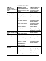
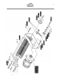
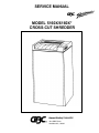
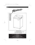
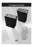
1
1.0 INTRODUCTION
This service manual covers adjustment, disassembly, operation, preventative
maintenance, troubleshooting procedures and contains an illustrated parts list
for the GBC Shredmaster 5160x shredder. The GBC Shredmaster 5160x is a
cross-cut, console shredder designed for higher volume requirements.
*Begining mid year 1997, the 5160x will be renamed as the 6160x. The 6160x is identical
to the 5160x with the exception of a new top cover label.
Innovative engineering has provided this shredder with the following operating
and safety features:
1. Automatic Operation - The unit begins to operate when a light beam is
broken as paper is inserted into the shredder throat. The motor stops running
when the light beam is no longer broken and the paper has had an
opportunity to clear the cutting head.
2. Overload Warning - Whenever the capacity of the shredder is exceeded the
unit stops shredding and the “Reverse” symbol illuminates.
3. Thermal Protection - The motor is equipped with a thermal protection device
which is triggered if the motor temperature reaches a predetermined level.
The motor will not operate until it cools.
4. Bag Full Sensor - When the shred bag becomes full, the motor automatically
turns off and the “Bag” light symbol illuminates. The shredder will not operate
until the shredded material is either compressed down or emptied.
5. Door Ajar Sensor - When the door of the shredder is not fully closed, the
“Door” light symbol illuminates. This is a safety feature that will only allow
the shredder to operate when the cabinet door is in the closed position.
Before using your GBC Shredmaster shredder, carefully read the operating
instructions in this manual. Once you have gained experience and familiarity
with its operation, you will be better equipped to use the remaining sections of
this manual to troubleshoot and repair the shredder.
2
2.0 SPECIFICATIONS
Required
Electrical
Service:
115V AC +/ - 10%, 60 Hz,
15 AMP, Two Wire Service with Ground
Electrical
Rating:
115V AC
9.15AMPS
Single Phase
3/5 Output HP @ 962 Watts, 9.15A,
Thermally Protected
Motor:
Motor
Duty Cycle:
Continuous Duty
Power
Consumption:
1000.05 Watts @ 17 Sheets, Nominal
Line
Dimensions:
38.50” High
24.00” Wide
22.00” Deep
Weight:
245 Pounds
Shredding
Speed:
26.5ft/min. @ 1 sheet, 18.5ft/min. @ 18
sheets
Shred Size:
3/16” x 2 3/8” (4mm x 60mm)
Feed Throat
Width:
16”
Shredder
Capacity:
18 -22 sheets of 8.5” x 11”
20# Bond Paper
Noise Level:
67.5 No Load, 81.0 Full Load
Bag Size:
48”H, 24”W, 18”D
Shipping Box Dimensions
LxWxH
Head 28¾”, 27¼”, 15”
Cabinet 28¾”,26½”,38¼”
3
3.0 INSTALLATION PROCEDURES
Figure 1
CAUTION: Two people are
required for the below
installation procedure.
1. Using the hand grips (a) provided “figure
1”, place the machine head
into the top of the cabinet. The
control panel may face toward the front
or back of the cabinet.
2. Open the door by pressing on the
door knob and place the hand grips
(a) located in the cabinet base (b) “figure
2”, into the holes found in
the cabinet.
3. Insert a plastic bag into the bag
frame from the under side of the
rail; fold over all four sides and
slide back into the guide rails.
4. Connect the power cord to a single
phase socket rated at 15 amps.
Figure 2
4
4.0 OPERATING INSTRUCTIONS
The GBC 5160X shredder can shred most office paper and documents.
However, the shredding of paper clips and other metal items may cause damage
to the shredder. Plastic materials such as credit cards, covers, inserts and film
should be avoided as they may lodge in the cutting head and prematurely dull
the cutters.
Operation
Please refer to the shredder control panel shown in Figure 4.1.
1. To begin using the shredder, press
the rocker switch (a) to the on position
“I”. The green control light (b) will
illuminate. The shredder is now in the
stand-by mode and will automatically
start shredding when paper is inserted.
When shredding is complete the
machine will automatically stop and
return to the stand-by mode.
2. If the bag full control light (c) is on,
the shredder bag must be changed.
3. For safety concerns the machine
will not operate when the cabinet door
is open. The red control symbol (d) will
light.
4. Whenever the shred capacity has
been exceeded, the unit will stop
shredding. The reverse symbol “R” (e)
will light. Press the rocker switch (a)
Figure 4.1
into position “R” and reduce the paper
stack and begin shredding again. In the case of a severe jam, it may be
necessary to tear off the paper as close to the
throat as possible. Then alternately rock the control switch between the Forward
and Reverse positions until the jam has cleared the cutting head. During this
operation, the thermal overload protector of the motor may be triggered and the
motor will appear inoperable. Wait a few minutes to allow the motor to cool,
then clear the jam.
5. Waste that does not need to be shredded can be thrown into the waste flap
area.
A = Rocker control Switch
C = Bag full Symbol
E = Reverse Symbol
B = Stand-by Control Symbol
D = Door ajar Symbol
5
5.O TROUBLESHOOTING
5.1 Mechanical Operation
The shredder uses two rotating
cutting shafts, which are driven by
an electrical motor to shred paper.
Both the upper and lower cutters are
precisely milled with a helix. The
cutter blades are progressively
staggered and give the cutters a
spiraling effect. The upper and
lower cutter blades are meshed with
each other and the cutting teeth are
timed to engage each other at
precisely the right point. Cutter
timing is explained in Section 6.8.
When the shredder is in the standby mode and the door of the
shredder is opened, the door ajar
icon illuminates. The control board
disables the circuit that provides
power to the motor until the door is
closed.
5.2 Electrical Operation
When the shredder is severely
loaded down, the control board turns
on the reverse symbol icon and
disables the circuit to the motor.
When the rocker standby/off
/reverse switch (S1) is depressed in
the “I” position, the green control
light will illuminate to indicate the
shredder is in the standby mode.
Power is supplied from the hot side
of the circuit to the following
components; the circuit breaker,
contactor, motor and the control
board. The neutral line is fed
through the contactor and to the
control board.
When the photocells sense paper in
the throat area, the circuit is
completed through the control board
allowing the contactor to
supply power to the motor.
When the bag full flap switch is
opened, the bag full icon will
illuminate. The control board then
disables the circuit to the motor until
the shredder is cleared or emptied.
5.3 Electrical Components
Motor - The motor is a single phase
3/5 HP, thermally protected
gearmotor, which is designed for
continuous operation.
Capacitors - (30uF & 40uF) These
capacitors assist the motor in
starting and running.
6
5.O TROUBLESHOOTING
5.3 Electrical Components
Stand-by/Off/Reverse Switch - The
Stand-by/Off/Reverse switch, when
depressed, connects the hot
and neutral circuits to electrical
components of the shredder.
Door , Bag and Reverse Indicators These LED’s illuminate when the
following condition occurs; When
the door is open, the shred bag is full or
when the shredder is jammed.
5.4 Testing Electrical Components
Machine Head Safety Sensors - The
safety sensors are both normally open
hall effect switches which are actuated
by a magnet inside of the cabinet door
and the back panel of the cabinet. The
switches are normally closed when the
door is closed and when the machine
head is installed on the cabinet.
Flap Switch - The flap switch is a
normally open switch actuated by the
bag full flap. When the shred bag
becomes full of shredded material, the
bag full flap is pushed back and power
is then removed from the motor circuit.
Emitter - The infrared light beam from
the light emitting diode is sensed by the
receiver to activate/deactivate the
control board.
Receiver - The receiver is a light
activated diode which works in
conjunction with the emitter to
activate/deactivate the control board.
WARNING: Always
disconnect the power cord from
receptacle before making continuity
or resistance tests.
Switches
Set meter to read resistance. Check
switches for continuity from common to
closed contacts and infinity from
common to the open contact.
Emitter - Set meter to the diode setting.
Disconnect emitters from the control
board. With the positive meter probe on
the black stripped emitter wire and the
negative meter probe on the gray
emitter wire, check for .737 ohms.
Reverse the meter leads and infinity
should be read.
Receiver - Set meter to read 20M
ohms. Disconnect the receiver from the
control board. With the positive meter
probe on the gray wire and the negative
meter probe on the black receiver wire
check for 1.47 Mega ohms under
normal room light. The resistance will
increase when blocked. Reverse the
meter leads and infinity should be read.
7
5.O TROUBLESHOOTING
5.4 Testing Electrical Components (cont.)
Circuit Breaker - Continuity should be read across the two terminals
when the breaker pin is pushed in and Infinity is read when tripped.
Forward Contactor - Set dvm for 200VAC. Check output voltage @
terminal 2T1 (black lead) and terminal block point Z (gray lead) for 213VAC
when the sensors are blocked and in the run mode. Contactor resistance across
A1 & A2 should read 140 ohms.
Reverse Contactor - Set dvm for 200VAC. Check output voltage @ terminal
4T2 & 6T3 for 115VAC when the control switch is depressed in the reverse
position. Contactor resistance across A1 & A2 should read 140 ohms.
Control Board Output Voltages - Set dvm to read 200 VAC.
• Pc board output voltage to the forward contactor should read 115VAC across
pins 6 & 7 with the sensors blocked and in the run position.
• Pc board output voltage to the reverse contactor should read 115VAC across
pins 6 & 8 with the sensors blocked and in the reverse mode.
• Pc board output voltage to the control switch should read 115VAC across pins
1 & 3 and 2 & 3 when the control switch is in the off position.
• Pc board output voltage to the emitter and receiver should read 3.14dc across
pins 3 & 4 and .10vdc across pins 1 & 2 when the emitter and receiver are
disconnected.
• Pc board output voltage to the safety sensors should read 11.82vdc between
pins 1 & 2 of x5 and x6 when both sensors are disconnected.
8
5.O TROUBLESHOOTING
5.5 General Troubleshooting
Malfunction corrections are based on visual observations made by the operator.
The causes of the malfunctions are isolated by the symptom of the malfunction
and noting at which point in the operating cycle the malfunction occurred.
Malfunctions may be pinpointed to a defective electrical component or
mechanical part by referring to the Principles of Operation, the troubleshooting
guide and the wiring diagram.
5.6 Troubleshooting Chart
The troubleshooting guide chart that follows is arranged in order of the normal
operational sequence. When a malfunction occurs, read down the SYMPTOM
column until you find the appropriate description for your symptom. Read the
corresponding PROBABLE CAUSE, then perform the recommended procedure
in the CORRECTIVE ACTION column. When replacing electrical components
that have push on terminals, label the electrical leads that were removed, to
facilitate reconnecting them. Refer to the wiring diagram in Figure 5.7 to resolve
any wiring difficulties that may occur.
WARNING: Always unplug the shredder to avoid possible electrical
shock hazard before attempting to perform any repairs.
9
SYMPTOM
Shredder does not
operate, no Indication of
power
5.0 TROUBLESHOOTING
PROBABLE CAUSE
Power cord disconnected.
Stand-by/Off/Reverse switch Test (section 5.4) and
replace if necessary
defective
Close door
Cabinet door open
Shredder does not
operate, with indication of
Shred bag full
power present
Shredder does not
operate, (automatic mode
only)
Shredder runs
continuously
CORRECTIVE ACTION
Connect power cord
Empty bag
Motor thermal cut off
triggered
Allow motor to cool
Door sensor defective
Test (section 5.4) and
replace if necessary
Control board defective
Test (section 5.4) and
replace if necessary
Defective capacitor
Replace capacitor
Motor defective
Check motor input voltage
replace motor if necessary
Test (section 5.4) and
replace if necessary
Photo diode defective
Control board defective
Defective forward/reverse
switch
Test (section 5.4) and
replace if necessary
Dust or scratch on photo
sensors
Clean or replace
Defective PC board
Test (section 5.4) and
replace if necessary
Receiver defective
Sheet capacity
diminished
Emitter defective
Cutters need lubrication
Cutters out of time
Lubricate cutters
Dull cutters
Time cutters (See Figure
6.8)
Replace cutters
Worn bearings
Replace bearings
10
5.0 TROUBLESHOOTING
5.7 Wiring Diagram
11
6.0 DISASSEMBLY/ASSEMBLY/
ADJUSTMENTS
6.1 Necessary Tools
leads and control switch leads.
The following tool list is necessary
for disassembly/assembly/
adjustments.
1. Phillips screwdriver, #1 tip
2. Phillips screwdriver, #2 tip
3. Gear puller 6” jaws
4. ½ “ socket w/ratchet
5. Vise grips, standard size
6. Snap ring pliers
7. Volt/ohm multimeter
8. Amprobe
9. Hammer
10. Metric wrenches - 8mm, 10mm
11. Metric hex keys
12. Adjustable wrench
6.2 Upper Cover Removal
Disassembly of the shredder is
described in the following steps.
Referencing Section 8.0 will help
you understand the text.
CAUTION!
Disconnect the unit from the
receptacle before performing any
disassembly procedures.
1. With the shredder upside down,
remove the twelve phillips head
screws from the base lip.
2. Remove and carefully place the
cover to one side.
3. Disconnect the wiring harness
from the control panel board.
4. After noting the wire sequence,
disconnect the circuit breaker,
5. Noting wire sequence, unscrew
the power cord leads from the
terminal block with a straight
blade jewelers screw driver.
6.3 Bottom Cover Removal
1. Complete Section 6.2, Upper
Cover Removal.
2. Disconnect the ground wire from
the side frame.
3. Remove the six hex head
screws from the bottom cover
using a 10mm socket and driver.
4. Disconnect the front and rear
sensors from the control board.
5. Slide the cutter assembly out of
the bottom cover.
6.4 Motor Removal
1. Complete Section 6.2, Upper
Cover Removal.
2. Complete Section 6.3, Lower
Cover Removal.
3. Disconnect leads X3, X4, 5 and 6
from the control board.
4. Noting the wiring sequence,
disconnect the coded wires 1 - 9
from the control board.
5. Removed the control board.
6. Unscrew the nylon control board
posts.
7. Remove the control board
insulator.
12
6.0 DISASSEMBLY/ASSEMBLY/
ADJUSTMENTS
6.4 Motor Removal (cont.)
8. Remove the four 10mm hex head
screws from the gear cover.
9. Remove ground strap from RH side
frame.
10. Remove master link from chain,
remove chain.
11. Remove four 13mm motor bolts.
12. Disconnect the motor wiring
harness and ground lead.
13. Slide the motor towards the inside
of chassis.
6.5 Gearbox Chassis Removal
1. Complete Section 6.2, Upper Cover
Removal.
2. Complete Section 6.3, Lower Cover
Removal.
3. Complete Section 6.4, Motor
Removal.
4. Remove two 5mm allen head screws
and washers from the main cutter
gear and upper cutter drive gear.
5. Using a gear puller, remove the main
cutter gear assembly.
6. Remove the upper cutter gear.
⇒ Please note the orientation of the
cutters key ways for assembly
purposes. They must be in series for
proper timing.
6. Remove two deflectors from each
side by removing two pan
head screws from each side.
7. Remove four nuts and two hex head
bolts (13mm & 15mm) from
the gear box chassis. The chassis can
now be removed.
6.6 Cutter Shaft and Stripper
Assembly Removal
1. Complete Section 6.2, Upper Cover
Removal.
2. Complete Section 6.3, Lower Cover
Removal.
3. Complete Section 6.4, Motor
Removal.
4. Complete Section 6.5, Motor Chassis
Removal
5. Remove two 13mm hex head bolts
(opposite of the motor side) from
support bars.
6. Remove the bag full spring.
7. Remove four 15mm lock nuts from
left hand side frame.
8. Remove plastic deflectors from the
cutting head.
9. Remove side support bracket from
left hand side.
CAUTION!
Sharp Objects!
Gloves must be worn before
proceeding!
10. Carefully Maneuver cutting head
assembly out towards motor side.
11. Remove three side plate supports
and shims from each side cutter
assembly.
12. Separated cutters.
13. Slide the four cross support bars out
from the strippers.
14. Slide strippers and fillers out from
the cutters.
13
6.0 DISASSEMBLY/ASSEMBLY/
ADJUSTMENTS
6.7 Assembly
1. The shredder is easily assembled by following the disassembly instructions in
the reverse order.
2. The cutter gears must be timed before installing the chain.
6.8 Cutter Timing
Before installing the cutter gears, check the cutter shaft key ways to ensure that
they are in series (Figure 6.1). Slight rotation of the cutter gears may be
necessary to align the teeth of the gears when installing. Before installing the
drive chain, test by manually shredding one sheet of paper. Failure to align the
cutters as shown in “Figure 6.1” will result in incomplete shredding and reduced
shred capacity.
Figure 6.1
14
7.0 MAINTENANCE PROCEDURES
7.1 External Cleaning
Make sure you disconnect the shredder from its power source before cleaning.
The cover and cabinet may be cleaned with a soft cloth moistened with a mild
detergent and warm water. Do not use chemical cleaners or solvents as these
may have a harmful effect. Use detergent sparingly to avoid contact with
electronic components.
METHOD B
7.2 Inspection
1. Spray an ”S” pattern of
Whenever the cover has been
lubricant across scrap sheets
removed for corrective maintenance,
of paper.
visually inspect for defects such as
loose screws or nuts, damaged wire
2. Turn the shredder on, shred the
insulation, loose terminals, etc.
lubricated sheets.
Correct any defects before returning
the shredder into service.
3. When shredding is complete,
reverse the shredder direction to
7.3 Lubrication
help distribute the lubricant
throughout the cutters.
The 5160x should be lubricated
whenever a decrease in sheet
4. Repeat these three steps until
capacity is noticed. Use a lubricant
shredder capacity is restored.
such as E-Z-1 oil (P/N 1961508)
which does not attract dust.
No periodic lubrication of the cutter
gears is required. However, when
Following the steps below will help
gears are replaced they should be
the 5160X maintain maximum sheet
lubricated with a good quality gear
capacity and efficiency.
lubricant.
METHOD A
1. With the shredder off, spray a
steady stream of lubricant into
the throat area from side to side.
2. Run the shredder in both
directions for a few seconds; this
will help distribute the lubricant
throughout the cutters.
15
8.0 PARTS LIST
All parts in each illustration are keyed with an index number for reference to the
respective part number, part name and quantity in the parts list. The quantities
for the 5160X shredder are shown in the respective quantity column.
When ordering service parts, always include the following information:
•
Machine Model Number
•
Machine Serial Number
•
Part Number
•
Part Name
•
Quantity Required
NOTE: The Northbrook Service Parts Department does not stock all hardware.
To avoid delay, standard hardware shown in this parts list should be procured
locally whenever possible.
5160X
PARTS LIST
FIGURE 8.1
16
5160X
PARTS LIST
FIGURE 8.2
17
5160X
PARTS LIST
FIGURE 8.3
18
5160X
PARTS LIST
FIGURE 8.4
19
5160X
PARTS LIST
FIGURE 8.5
20
5160X
PARTS LIST
FIGURE 8.6
21
SERVICE MANUAL
MODEL 5160X/6160X*
CROSS-CUT SHREDDER
One GBC Plaza
Northbrook IL, 60662
Issued:
08/00
5160X WIRING DIGRAM
10