1
Technical Service Manual
R-410A Split System
16~18 SEER, Inverter Systems - 60 and 50 Hz
Single Split
4MYW8-A
June 2010
4TYK8-A
Warnings, Cautions and Notices
Warnings, Cautions and Notices. Note that warnings, cautions and notices appear at
appropriate intervals throughout this manual. Warnings are provide to alert installing contractors
to potential hazards that could result in personal injury or death. Cautions are designed to alert
personnel to hazardous situations that could result in personal injury, while notices indicate a
situation that could result in equipment or property-damage-only accidents.
Your personal safety and the proper operation of this machine depend upon the strict observance
of these precautions.
ATTENTION: Warnings, Cautions and Notices appear at appropriate sections throughout
this literature. Read these carefully.
WARNING: Indicates a potentially hazardous situation which, if not avoided, could
result in death or serious injury.
CAUTION: Indicates a potentially hazardous situation which, if not avoided, could
result in minor or moderate injury. It could also be used to alert against unsafe practices.
NOTICE: Indicates a situation that could result in equipment or property-damage only
accidents.
Important
Environmental Concerns!
Scientific research has shown that certain man-made chemicals can affect the earth's naturally
occurring stratospheric ozone layer when released to the atmosphere. In particular, several of the
identified chemicals that may affect the ozone layer are refrigerants that contain Chlorine, Fluorine
and Carbon (CFCs) and those containing Hydrogen, Chlorine, Fluorine and Carbon (HCFCs). Not all
refrigerants containing these compounds have the same potential impact to the environment.
Trane advocates the responsible handling of all refrigerants-including industry replacements for
CFCs such as HCFCs and HFCs.
Responsible Refrigerant Practices!
Trane believes that responsible refrigerant practices are important to the environment, our
customers, and the air conditioning industry. All technicians who handle refrigerants must be
certified. The Federal Clean Air Act (Section 608) sets forth the requirements for handling,
reclaiming, recovering and recycling of certain refrigerants and the equipment that is used in these
service procedures. In addition, some states or municipalities may have additional requirements
that must also be adhered to for responsible management of refrigerants. Know the applicable
laws and follow them.
WARNING
Electrocution and Fire Hazards with Improperly Installed and Grounded
Field Wiring!
Improperly installed and grounded field wiring poses FIRE & ELECTROCUTION hazards. To avoid
these hazards, you MUST follow requirements for field wiring installation and grounding as
described in the National Electrical Codes (NEC) and your local/state electrical codes. All field
wiring MUST be performed by qualified personnel. Failure to follow these requirements could
result in death or serious injury.
© 2010 Trane All rights reserved
WARNING
R410A Refrigerant under Higher Pressure than R22!
The units described in this manual use R410A refrigerant which operates at 50 to 70% higher
pressures than R-22. Use only R-410A approved service equipment. Refrigerant cylinders are
painted with "pink" color to indicate the type of refrigerant and may contain a "dip" tube to
allow for charging of liquid refrigerant into the system. For specific handling concerns with R410A, please contact your local Trane representative. Failure to use R-410A approved service
equipment could result in standard equipment exploding under R-410A higher pressure which
could result in death or serious injury.
NOTICE:
Use PVE Oil with R-410A Mini-Split Units!
All R-410A mini-splits use a PVE oil (Polyvinyl Ether Oil) that readily absorbs moisture from the
atmosphere. To limit this “hygroscopic” action, the system should remain sealed whenever
possible. If a system has been open to the atmosphere for more than 4 hours, the compressor oil
must be replaced. Never break a vacuum with air and always change the driers when opening
the system for component replacement. For specific handling concerns with PVE oil, contact
your local Trane representative.
USE ONLY THE FACTORY RECOMMENDED - DAFNE HERMETIC OIL FV50S - for servicing these
units.
3
5
13
Capacity Variation Ratio According to Pipe Length
15
System
16
Electrical Characteristics
17
18
18
19
20
28
32
33
34
34
34
34
36
38
40
40
54
59
59
64
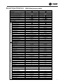
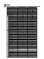
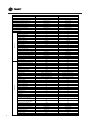
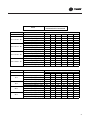
0RGHO6SHFLILFDWLRQV
Model
Function
60Hz Heat pump models
4MXW5509A1 4TXK5509A1
COOLING
Rated Voltage
HEATING
4MXW5512A1 4TXK5512A1
COOLING
208-230V
Frequency(Hz)
HEATING
208-230V
60
60
Total Capacity (W) (High/Standard/Low *):
3370/2579/1113
3370/2608/967
3663/3400/967
3663/3575/996
Total Capacity (Btu/h) (High/ Standard/Low *):
11500/8800/3800
11500/8900/3300
12500/11600/3300
12500/12200/3400
1220/760/270
980/650/230
1340/1130/260
1000/940/260
5.3/4.7
6.6/6.0
6.4/5.8
6.9/6.2
17.5
9
18
9
Power Input (W) (High/ Standard/Low *)
Nominal Input Current (A)
SEER/HSPF
Air Flow Volume (m 3/h) (SH/H/M/L)**
Dehumidifying Volume (l/h)
EER / C.O.P (W/W)
Model of Indoor Unit
Fan Motor Speed (r/min) (SH/H/M/L)
Output of Fan Motor (w)
Fan Motor RLA(A)
Fan Motor Capacitor (uF)
Fan Type-Piece
Diameter-Length (mm)
Indoor unit
Evaporator
Pipe Diameter (mm)
Row-Fin Gap(mm)
Coil length (l) x height (H) x coil width (L)
Swing Motor Model
Output of Swing Motor (W)
Fuse (A)
580/520/440/370
0.8
1.4
3.4/4.0
3.0/3.8
4MXW5509A1
1300/1100/900/700 1300/1150/980/820
4MXW5512A1
1350/1150/950/750 1350/1200/100/850
15
15
0.19
0.19
1.2
1.2
Cross-flow
Cross-flow
φ92X595.5
φ92X595.5
Aluminum Fin-copper Tube
Aluminum Fin-copper Tube
φ7
φ7
2-1.4
2-1.4
610X24X294
610X24X294
MP24BA
MP24BA
1.5
1.5
PCB 3.15A Transformer 0.2A
PCB 3.15A Transformer 0.2A
Sound Pressure Level dB (A) (SH/H/M/L)
43/38/32/26
44/39/33/28
Sound Power Level dB (A) (SH/H/M/L)***
53/48/42/36
54/49/43/38
Dimension (W/H/D) ( mm)
770X283X201
770X283X201
Dimension of Package (L/W/H) ( mm)
847X264X357
847X264X357
Net Weight /Gross Weight (kg)
8.5/11.5
9/12
Room Temp. sensor
15K
15K
Pipe Temp. sensor
Model of Outdoor Unit
20K
20K
4TXK5509A1
4TXK5512A1
Compressor Manufacturer/trademark
Gree
Gree
Compressor Model
1YC23AEXD
1YC23AEXD
Compressor Type
Rotary
Rotary
L.R.A. (A)
6.1
6.1
Compressor RLA(A)
6.1
6.1
Compressor Power Input(W)
600
600
Overload Protector
Throttling Method
Starting Method
Working Temp Range (℃)
Condenser
CS-7SA
CS-7SA
Capillary
Capacitor
Capillary
Capacitor
(-15)℃≤T≤24℃
18℃≤T≤48℃
AluminumFin-copperTube
(-15)℃≤T≤24℃
18℃≤T≤48℃
AluminumFin-copperTube
Pipe Diameter (mm)
φ7
φ7
Rows-Fin Gap(mm)
1-1.4
2-1.4
647X528X19.05
≤930
647X528X38.1
≤930
Coil length (l) x height (H) x coil width (L)
Fan Motor Speed (rpm)
Output of Fan Motor (W)
Outdoor unit
560/510/440/370
Fan Motor RLA(A)
Fan Motor Capacitor (uF)
Air Flow Volume of Outdoor Unit m3/h
Fan Type-Piece
21
21
0.17
0.17
2
2
1600
1600
Axial-flow
Axial-flow
Fan Diameter (mm)
370
370
Defrosting Method
Automatic Defrosting
Automatic Defrosting
T1
T1
Climate Type
Isolation
Moisture Protection
Permissible Excessive Operating Pressure
for the Discharge Side(MPa)
Permissible Excessive Operating Pressure
for the Suction Side(MPa)
Sound Pressure Level dB (A)
I
I
IP24
IP24
3.8
3.8
1.2
1.2
≤49
≤52
Sound Power Level dB (A)
≤59
≤62
Dimension (W/H/D) ( mm)
710X550X318
710X550X318
Dimension of Package (L/W/H)( mm)
774X351X607
774X351X607
Net Weight /Gross Weight (kg)
28/32
30/34
R410A/0.74
R410A/1.00
Temp.sensor
15K
15K
Pipe Temp. sensor
Discharge sensor
20K
50K
20K
50K
Refrigerant Charge (kg)
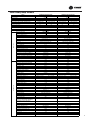
5
Model
Function
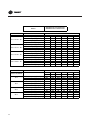
4MXW5518A1 4TXK5518A1
COOLING
Rated Voltage
HEATING
Total Capacity (Btu/h) (High/ Standard/Low *):
Power Input (W) (High/ Standard/Low *)
Nominal Input Current (A)
SEER/HSPF
3
Air Flow Volume (m /h) (SH/H/M/L)**
Dehumidifying Volume (l/h)
EER / C.O.P (W/W)
Model of Indoor Unit
Fan Motor Speed (r/min) (SH/H/M/L)
Output of Fan Motor (w)
Fan Motor RLA(A)
Fan Motor Capacitor (uF)
Fan Type-Piece
Diameter-Length (mm)
Indoor unit
Evaporator
Pipe Diameter (mm)
Row-Fin Gap(mm)
Coil length (l) x height (H) x coil width (L)
Swing Motor Model
Output of Swing Motor (W)
60
6687/5715/1172
7033/6447/1875
8030/7913/1201
21000/18200/4500
24000/19500/4000
24000/22100/6400
27400/27000/4100
2600/1660/200
2750/2110/300
2550/2380/300
2850/2720/320
8.1/7.3
9.3/8.4
11.5/10.5
14.2/12.8
16.5
8.2
17
9.7
800/680/560/460
1000/800/700/600
1.8
2
3.2/2.7
2.7/2.9
4MXW5518A1
4MXW5524A1
1400/1150/1000/850 1450/1250/1100/950 1350/1150/1000/850 1350/1150/1000/900
20
35
0.31
0.31
1.5
2.5
Cross-flow
Cross-flow
Φ98X650
Φ98X765
Aluminum Fin-copper Tube
Aluminum Fin-copper Tube
φ7
φ7
2-1.4
2-1.5
657X304.8X25.4
765X342.9X25.4
MP28VB
MP35XX
2.5
PCB 3.15A Transformer 0.2A
PCB 3.15A Transformer 0.2A
Sound Pressure Level dB (A) (SH/H/M/L)
48/43/38/34
49/43/39/34
Sound Power Level dB (A) (SH/H/M/L)***
58/53/48/44
59/53/49/44
Dimension (W/H/D) ( mm)
865x305x215
1008x319x221
Dimension of Package (L/W/H) ( mm)
948X383X310
1076x398x328
12/16
15/20
Net Weight /Gross Weight (kg)
Room Temp. sensor
15K
15K
Pipe Temp. sensor
Model of Outdoor Unit
20K
20K
4TXK5518A1
4TXK5524A1
Compressor Manufacturer/trademark
Sanyo
Sanyo
Compressor Model
C-6RZ146H1A
C-6RZ146H1A
Compressor Type
Twin Rotary
Twin Rotary
L.R.A. (A)
41
41
Compressor RLA(A)
8.4
8.4
Compressor Power Input(W)
Overload Protector
Throttling Method
Starting Method
Working Temp Range (℃)
Condenser
1640
1640
1NT11L-3979
1NT11L-3979
Electronic expansion valve
Capacitor
Electronic expansion valve
Capacitor
(-15)℃≤T≤24℃
18℃≤T≤48℃
AluminumFin-copperTube
(-15)℃≤T≤24℃
18℃≤T≤48℃
AluminumFin-copperTube
Pipe Diameter (mm)
φ7
φ7
Rows-Fin Gap(mm)
2-1.4
2-1.4
837x660x38.1
≤690
853X660X38.1
≤690
Coil length (l) x height (H) x coil width (L)
Fan Motor Speed (rpm)
Output of Fan Motor (W)
Outdoor unit
60
6154/5334/1318
2
Fuse (A)
Fan Motor RLA(A)
Fan Motor Capacitor (uF)
Air Flow Volume of Outdoor Unit m3/h
Fan Type-Piece
60
60
0.58
0.59
3.5
3.5
3200
3200
Axial-flow
Axial-flow
Fan Diameter (mm)
520
520
Defrosting Method
Automatic Defrosting
Auto defrosting
T1
T1
Climate Type
Isolation
I
I
IP24
IP24
3.8
3.8
Moisture Protection
Permissible Excessive Operating Pressure
for the Discharge Side(MPa)
Permissible Excessive Operating Pressure
for the Suction Side(MPa)
Sound Pressure Level dB (A)
1.2
1.2
≤56
≤56
Sound Power Level dB (A)
≤66
≤56
Dimension (W/H/D) ( mm)
955X700X396
955X700X396
Dimension of Package (L/W/H)( mm)
1029X458X750
1029X458X750
Net Weight /Gross Weight (kg)
52/57
51/56
R410A/1.25
R410A/1.55
Temp.sensor
15K
15K
Pipe Temp. sensor
Discharge sensor
20K
50K
20K
50K
Refrigerant Charge (kg)
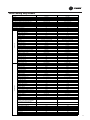
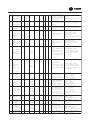
6
HEATING
208-230V
208-230V
Frequency(Hz)
Total Capacity (W) (High/Standard/Low *):
4MXW5524A1 4TXK5524A1
COOLING
60Hz Cooling only models
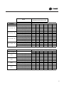
Model
4MYW5509A1 4TYK5509A1
4MYW5512A1 4TYK5512A1
Function
COOLING
COOLING
Rated Voltage
208-230V
208-230V
Frequency(Hz)
60
60
Total Capacity (W) (High/Standard/Low *):
3370/2579/1113
3663/3400/967
Total Capacity (Btu/h) (High/ Standard/Low *):
11500/8800/3800
12500/11600/3300
1220/760/270
1340/1130/260
5.3/4.7
6.4/5.8
Power Input (W) (High/ Standard/Low *)
Nominal Current (A)
SEER/HSPF
17.5
18
560/510/440/370
580/520/440/370
Dehumidifying Volume (l/h)
0.8
1.4
EER / C.O.P (W/W)
Model of Indoor Unit
3.4
3.0
4MYW5509A1
1300/1100/900/700
4MYW5512A1
1350/1150/950/750
Air Flow Volume (m 3/h) (SH/H/M/L)**
Fan Motor Speed (r/min) (SH/H/M/L)
Output of Fan Motor (w)
15
15
Fan Motor Capacitor (uF)
1.2
1.2
0.19
Cross-flow
0.19
Cross-flow
Fan Motor RLA(A)
Fan Type-Piece
Diameter-Length (mm)
Indoor unit
Evaporator
Pipe Diameter (mm)
Row-Fin Gap(mm)
Coil length (l) x height (H) x coil width (L)
Swing Motor Model
Output of Swing Motor (W)
Fuse (A)
Sound Pressure Level dB (A) (SH/H/M/L)
Sound Power Level dB (A) (SH/H/M/L)***
Dimension (W/H/D) ( mm)
Dimension of Package (L/W/H) ( mm)
Net Weight /Gross Weight (kg)
φ92X595.5
Aluminum Fin-copper Tube
φ7
φ7
2-1.4
610X24X294
MP24BA
2-1.4
610X24X294
MP24BA
1.5
1.5
PCB 3.15A Transformer 0.2A
43/38/32/26
53/48/42/36
770X283X201
PCB 3.15A Transformer 0.2A
44/39/33/28
54/49/43/38
770X283X201
847X264X357
847X264X357
8.5/11.5
9/12
Room Temp. sensor
15K
15K
Pipe Temp. sensor
Model of Outdoor Unit
20K
20K
4TYK5509A1
4TYK5512A1
Compressor Model
Gree
1YC23AEXD
Gree
1YC23AEXD
Compressor Type
Compressor Manufacturer/trademark
Rotary
Rotary
L.R.A. (A)
6.1
6.1
Compressor RLA(A)
6.1
600
6.1
600
Compressor Power Input(W)
Overload Protector
Throttling Method
Starting Method
Working Temp Range (℃)
Condenser
Pipe Diameter (mm)
Rows-Fin Gap(mm)
Coil length (l) x height (H) x coil width (L)
Fan Motor Speed (rpm)
Output of Fan Motor (W)
Outdoor unit
φ92X595.5
Aluminum Fin-copper Tube
Fan Motor RLA(A)
Fan Motor Capacitor (uF)
Air Flow Volume of Outdoor Unit m3/h
Fan Type-Piece
CS-7SA
CS-7SA
Capillary
Capacitor
Capillary
Capacitor
18℃≤T≤48℃
AluminumFin-copperTube
18℃≤T≤48℃
AluminumFin-copperTube
φ7
φ7
1-1.4
647X528X19.05
≤930
21
2-1.4
647X528X38.1
≤930
21
0.17
0.17
2
2
1600
1600
Axial-flow
Axial-flow
Fan Diameter (mm)
370
370
Defrosting Method
-
-
T1
T1
I
IP24
I
IP24
3.8
3.8
1.2
≤49
1.2
≤52
Dimension (W/H/D) ( mm)
≤59
710X550X318
≤62
710X550X318
Dimension of Package (L/W/H)( mm)
774X351X607
774X351X607
Climate Type
Isolation
Moisture Protection
Permissible Excessive Operating
Pressure for the Discharge Side(MPa)
Permissible Excessive Operating
Pressure for the Suction Side(MPa)
Sound Pressure Level dB (A)
Sound Power Level dB (A)
Net Weight /Gross Weight (kg)
Refrigerant Charge (kg)
28/32
30/34
R410A/0.74
R410A/1.00
Temp.sensor
15K
15K
Pipe Temp. sensor
Discharge sensor
20K
50K
20K
50K
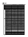
7
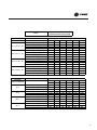
Model
4MYW5518A1 4TYK5518A1
4MYW5524A1 4TYK5524A1
Function
COOLING
COOLING
Rated Voltage
208-230V
208-230V
Frequency(Hz)
60
60
6154/5334/1318
7033/6447/1875
21000/18200/4500
24000/22100/6400
2600/1660/200
2550/2380/300
8.1/7.3
11.5/10.5
Total Capacity (W) (High/Standard/Low *):
Total Capacity (Btu/h) (High/ Standard/Low *):
Power Input (W) (High/ Standard/Low *)
Nominal Current (A)
SEER/HSPF
Air Flow Volume (m 3/h) (SH/H/M/L)**
17
800/680/560/460
1000/800/700/600
Dehumidifying Volume (l/h)
1.8
2
EER / C.O.P (W/W)
Model of Indoor Unit
3.2
2.7
4MYW5518A1
1400/1150/1000/850
4MYW5524A1
1350/1150/1000/850
Fan Motor Speed (r/min) (SH/H/M/L)
Output of Fan Motor (w)
20
35
Fan Motor Capacitor (uF)
1.5
2.5
0.31
Cross-flow
0.31
Cross-flow
Fan Motor RLA(A)
Fan Type-Piece
Diameter-Length (mm)
Indoor unit
Evaporator
Pipe Diameter (mm)
Row-Fin Gap(mm)
Coil length (l) x height (H) x coil width (L)
Swing Motor Model
Output of Swing Motor (W)
Fuse (A)
Sound Pressure Level dB (A) (SH/H/M/L)
Sound Power Level dB (A) (SH/H/M/L)***
Dimension (W/H/D) ( mm)
Dimension of Package (L/W/H) ( mm)
Net Weight /Gross Weight (kg)
Φ98X765
Aluminum Fin-copper Tube
φ7
φ7
2-1.4
657X304.8X25.4
MP28VB
2-1.5
765X342.9X25.4
MP35XX
2
PCB 3.15A Transformer 0.2A
48/43/38/34
58/53/48/44
865x305x215
PCB 3.15A Transformer 0.2A
49/43/39/34
59/53/49/44
1008x319x221
948X383X310
1076x398x328
12/16
15/20
2.5
15K
15K
Pipe Temp. sensor
Model of Outdoor Unit
20K
20K
4TYK5518A1
4TYK5524A1
Compressor Model
Sanyo
C-6RZ146H1A
Sanyo
C-6RZ146H1A
Compressor Type
Rotary
Rotary
L.R.A. (A)
41.00
41.00
Compressor RLA(A)
8.40
8.40
1640
1NT11L-3979
1640
1NT11L-3979
Electron expansion valve
Capacitor
Electron expansion valve
Capacitor
18℃≤T≤48℃
AluminumFin-copperTube
18℃≤T≤48℃
AluminumFin-copperTube
Compressor Power Input(W)
Overload Protector
Throttling Method
Starting Method
Working Temp Range (℃)
Condenser
Pipe Diameter (mm)
φ7
φ7
2-1.4
837x660x38.1
≤690
60
2-1.4
853X660X38.1
≤690
60
Fan Motor RLA(A)
0.58
0.59
Fan Motor Capacitor (uF)
3.5
3.5
3200
Axial-flow
3200
Axial-flow
Fan Diameter (mm)
520
520
Defrosting Method
-
-
T1
T1
I
IP24
I
IP24
3.8
3.8
1.2
≤56
1.2
≤56
Dimension (W/H/D) ( mm)
≤66
955X700X396
≤56
955X700X396
Dimension of Package (L/W/H)( mm)
1029X458X750
1029X458X750
Rows-Fin Gap(mm)
Coil length (l) x height (H) x coil width (L)
Fan Motor Speed (rpm)
Output of Fan Motor (W)
Outdoor unit
Φ98X650
Aluminum Fin-copper Tube
Room Temp. sensor
Compressor Manufacturer/trademark
Air Flow Volume of Outdoor Unit m3/h
Fan Type-Piece
Climate Type
Isolation
Moisture Protection
Permissible Excessive Operating
Pressure for the Discharge Side(MPa)
Permissible Excessive Operating
Pressure for the Suction Side(MPa)
Sound Pressure Level dB (A)
Sound Power Level dB (A)
Net Weight /Gross Weight (kg)
51/56
51/56
R410A/1.20
R410A/1.55
Temp.sensor
15K
15K
Pipe Temp. sensor
Discharge sensor
20K
50K
20K
50K
Refrigerant Charge (kg)
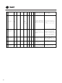
8
16.5
50Hz Heat pump models
Model
4MXW5509AB 4TXK5509AB
COOLING
Function
HEATING
Rated Voltage
Total Capacity (Btu/h) (High/ Standard/Low *):
Power Input (W) (High/ Standard/Low *)
HEATING
220-240V
Frequency(Hz)
Total Capacity (W) (High/Standard/Low *):
4MXW5512AB 4TXK5512AB
COOLING
220-240V
50
50
3230/2650/440
4100/3520/440
3960/3530/586
5130/4260/586
11000/9000/1500
14000/12000/1500
13500/12000/2000
17500/14500/2000
1350/800/200
1450/950/200
1450/1100/220
1550/1180/220
Nominal Current (A)
6.3
6.8
6.5
7.8
SEER/HSPF
17
9
17
Air Flow Volume (m 3/h) (SH/H/M/L)**
560/520/370/280
Dehumidifying Volume (l/h)
EER / C.O.P (W/W)
Model of Indoor Unit
Fan Motor Speed (r/min) (SH/H/M/L)
Output of Fan Motor (w)
Fan Motor Capacitor (uF)
Fan Motor RLA(A)
Fan Type-Piece
Diameter-Length (mm)
Indoor unit
Evaporator
Pipe Diameter (mm)
Row-Fin Gap(mm)
Coil length (l) x height (H) x coil width (L)
Swing Motor Model
1.4
0.8
3.3
3.7
4MXW5509AB
1300/1100/900/700
1300/1150/980/820
10
3.2
3.6
4MXW5512AB
1350/1150/950/750
1350/1200/100/850
10
1.2
1.2
0.16
0.16
Cross flow fan – 1
Cross flow fan – 1
φ92x594
φ92x594
Aluminum fin-copper tube
Aluminum fin-copper tube
φ7
φ7
2-1.4
610X294X24
MP24BA
2-1.4
610X294X24
MP24BA
1.5
1.5
Fuse (A)
PCB 3.15A
PCB 3.15A
Sound Pressure Level dB (A) (H/M/L)
43/36/30/24
44/37/31/25
Sound Power Level dB (A) (H/M/L)***
53/46/40/34
54/47/41/35
Dimension (W/H/D) ( mm)
770x283x201
770x283x201
Dimension of Package (L/W/H) ( mm)
Output of Swing Motor (W)
844x342x261
844x342x261
Net Weight /Gross Weight (kg)
8/11
9/12
Room Temp.Sensor
15K
15K
Pipe Temp.Sensor
20K
20K
Model of Outdoor Unit
Compressor Manufacturer/trademark
4TXK5509AB
4TXK5512AB
Gree
Gree
Compressor Model
1YC23AEXD
1YC23AEXD
Compressor Type
Rotary
Rotary
L.R.A. (A)
6.1
6.1
Compressor RLA(A)
6.1
6.1
Compressor Power Input(W)
600
600
Overload Protector
CS-7SA
CS-7SA
Throttling Method
Capillary
Capillary
Starting Method
Working Temp Range (℃)
Condenser
Transducer starting
(-15)℃≤T≤24℃
18℃≤T≤48℃
Aluminum fin-copper tube
Transducer starting
(-15)℃≤T≤24℃
18℃≤T≤48℃
Aluminum fin-copper tube
Pipe Diameter (mm)
φ7
φ7
Rows-Fin Gap(mm)
1-1.4
2-1.4
647X528X19.05
647X528X38.1
≤930
≤930
Coil length (l) x height (H) x coil width (L)
Fan Motor Speed (rpm)
Output of Fan Motor (W)
Outdoor unit
9
580/520/410/300
30
30
Fan Motor RLA(A)
0.23
0.23
Fan Motor Capacitor (uF)
Air Flow Volume of Outdoor Unit m3/h
Fan Type-Piece
2
2
1600
1600
Axial fan –1
Axial fan –1
Fan Diameter (mm)
370
370
Defrosting Method
Automatic Defrosting
Automatic Defrosting
T1
T1
Climate Type
Isolation
Moisture Protection
Permissible Excessive Operating
Pressure for the Discharge Side(MPa)
Permissible Excessive Operating
Pressure for the Suction Side(MPa)
Sound Pressure Level dB (A)
I
I
IP24
IP24
3.8
3.8
1.2
1.2
≤50
≤52
Sound Power Level dB (A)
Dimension (W/H/D) ( mm)
≤60
≤62
658x550x275
658x550x275
Dimension of Package (L/W/H)( mm)
771x348x592
771x348x592
Net Weight /Gross Weight (kg)
28/32
30/34
R410A/0.70
R410A/0.96
Temp.sensor
15K
15K
Pipe Temp. sensor
Discharge sensor
20K
50K
20K
50K
Refrigerant Charge (kg)
9
Model
4MXW5518AB 4TXK5518AB
COOLING
Function
HEATING
Power Input (W) (High/ Standard/Low *)
7000/5700/1000
7000/6450/1500
7800/7000/1200
22178/18080/3582
23884/19448/3412
23884/22007/5118
26613/23884/4094
2600/1578/350
2500/1985/350
2500/1600/360
Fan Motor Speed (r/min) (SH/H/M/L)
Output of Fan Motor (w)
Fan Motor Capacitor (uF)
Fan Motor RLA(A)
Fan Type-Piece
Diameter-Length (mm)
Indoor unit
Evaporator
Pipe Diameter (mm)
Row-Fin Gap(mm)
Coil length (l) x height (H) x coil width (L)
Swing Motor Model
Output of Swing Motor (W)
Fuse (A)
Sound Pressure Level dB (A) (H/M/L)
Sound Power Level dB (A) (H/M/L)***
Dimension (W/H/D) ( mm)
Dimension of Package (L/W/H) ( mm)
Net Weight /Gross Weight (kg)
Room Temp.Sensor
9
9
950/800/650/550
1.8
2
3.2
3.6
4MXW5518AB
1300/1100/950/800
1400/1200/1050/900
20
3.2
3.6
4MXW5524AB
1250/1100/950/800
1300/1100/1000/850
35
1.5
2.5
0.31
0.31
Cross flow fan – 1
Cross flow fan – 1
ij98X650
¶;
Aluminum Fin-copper Tube
Aluminum Fin-copper Tube
ij7
ij7
2-1.4
2-1.5
657X25.4X304.8
765X342.9X25.4
MP28VB
MP35XX
2
PCB 3.15A
(45)/40/37/32
55/50/47/42/865x305x215
948X383X310
12/16
15K
2.5
PCB 3.15A Transformer 0.2A
(46)/42/37/32
(560/52/47/42
1008x319x221
1076x398x328
15/20
15K
20K
20K
4TXK5518AB
4TXK5524AB
Sanyo
Sanyo
Compressor Model
C-6RZ146H1A
C-6RZ146H1A
Compressor Type
Twin Rotary
Twin Rotary
L.R.A. (A)
41
41
Compressor RLA(A)
8.4
8.4
Compressor Power Input(W)
Overload Protector
Throttling Method
Starting Method
Working Temp Range (ć)
Condenser
1640
1640
1NT11L-3979
1NT11L-3979
Capillary
Electron expansion valve
Transducer starting
(-15)ćİTİć
18ćİTİć
Aluminum Fin-copper Tube
Transducer starting
(-15)ćİTİć
18ćİTİć
Aluminum Fin-copper Tube
Pipe Diameter (mm)
ij7
ij7
Rows-Fin Gap(mm)
2-1.4
2-1.4
853x660x38.1
853X660X38.1
İ690
İ690
Coil length (l) x height (H) x coil width (L)
Fan Motor Speed (rpm)
Output of Fan Motor (W)
Outdoor unit
16.5
800/680/560/460
Model of Outdoor Unit
Compressor Manufacturer/trademark
Pipe Temp.Sensor
Fan Motor RLA(A)
Fan Motor Capacitor (uF)
Air Flow Volume of Outdoor Unit m3/h
Fan Type-Piece
60
60
0.58
0.58
3.5
3.5
3200
3200
Axial fan –1
Axial fan –1
Fan Diameter (mm)
520
520
Defrosting Method
Automatic Defrosting
Automatic Defrosting
T1
T1
Climate Type
Isolation
I
I
IP24
IP24
3.8
3.8
1.2
1.2
Sound Pressure Level dB (A)
İ54
İ54
Sound Power Level dB (A)
Dimension (W/H/D) ( mm)
İ64
İ64
955X700X396
955X700X396
Dimension of Package (L/W/H)( mm)
1029X458X750
1029x458x750
Moisture Protection
Permissible Excessive Operating
Pressure for the Discharge Side(MPa)
Permissible Excessive Operating
Pressure for the Suction Side(MPa)
Net Weight /Gross Weight (kg)
Refrigerant Charge (kg)
Temp.sensor
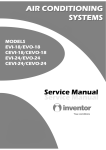
10
11.98
16.5
Dehumidifying Volume (l/h)
Model of Indoor Unit
2700/1930/350
11.6
3
Air Flow Volume (m /h) (SH/H/M/L)**
EER / C.O.P (W/W)
50
6500/5300/1050
Nominal Current (A)
SEER/HSPF
220-240V
50
Frequency(Hz)
Total Capacity (Btu/h) (High/ Standard/Low *):
HEATING
220-240V
Rated Voltage
Total Capacity (W) (High/Standard/Low *):
4MXW5524AB 4TXK5524AB
COOLING
Pipe Temp. sensor
Discharge sensor
52/57
52/57
R410A/1.25
R410A/1.40
15K
20K
50K
15K
20K
50K
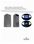
50Hz Cooling only models
Model
Function
Rated Voltage
Frequency(Hz)
Total Capacity (W)
Total Capacity (Btu/h) (High/ Standard/Low *):
Power Input (W) (High/ Standard/Low *)
Nominal Current (A)
SEER/HSPF
Air Flow Volume (m 3/h) (SH/H/M/L)**
Dehumidifying Volume (l/h)
EER / C.O.P (W/W)
Model of Indoor Unit
Fan Motor Speed (r/min) (SH/H/M/L)
COOLING
220-240V
50
3230/2650/440
11000/9000/1500
1350/800/200
6.3
17
560/520/370/280
0.8
3.3
220-240V
50
3960/3530/586
13500/12000/2000
1450/1100/220
6.5
17
580/520/410/300
1.4
3.2
4MYW5509AB
4MYW5512AB
1300/1100/900/700
1350/1150/950/750
10
10
Fan Motor Capacitor (uF)
1.2
1.2
Fan Type-Piece
Diameter-Length (mm)
Evaporator
Pipe Diameter (mm)
Indoor unit
4MYW5512AB 4TYK5512AB
COOLING
Output of Fan Motor (w)
Fan Motor RLA(A)
Row-Fin Gap(mm)
Coil length (l) x height (H) x coil width (L)
Swing Motor Model
Output of Swing Motor (W)
0.16
0.16
Cross flow fan – 1
Cross flow fan – 1
φ92X594
φ92X594
Aluminum fin-copper tube
Aluminum fin-copper tube
φ7
φ7
2-1.4
2-1.4
610X294X24
610X294X24
MP24BA
MP24BA
1.5
1.5
PCB 3.15A
PCB 3.15A
Sound Pressure Level dB (A) (H/M/L)
36/30/24
37/31/25
Sound Power Level dB (A) (H/M/L)***
46/40/34
47/41/35
Dimension (W/H/D) ( mm)
770x283x201
770x283x201
Dimension of Package (L/W/H) ( mm)
Fuse (A)
844x342x261
844x342x261
Net Weight /Gross Weight (kg)
8/11
9/12
Room Temp. sensor
15K
15K
Pipe Temp. sensor
20K
20K
Room Temp. sensor
15K
15K
Pipe Temp. sensor
20K
20K
4TYK5509AB
4TYK5512AB
Model of Outdoor Unit
Compressor Manufacturer/trademark
Gree
Gree
Compressor Model
1YC23AEXD
1YC23AEXD
Compressor Type
Rotary
Rotary
L.R.A. (A)
5.0
5.0
Compressor RLA(A)
5.0
5.0
Compressor Power Input(W)
Overload Protector
Throttling Method
Starting Method
Working Temp Range (℃)
Condenser
600
600
CS-7SA
CS-7SA
Capillary
Capillary
Transducer starting
Transducer starting
-7℃≤T≤43℃
Aluminum fin-copper tube
-7℃≤T≤43℃
Aluminum fin-copper tube
Pipe Diameter (mm)
7
7
Rows-Fin Gap(mm)
1-1.4
2-1.4
647X528X19.05
647X528X38.1
Output of Fan Motor (W)
≤930
30
≤930
30
Fan Motor RLA(A)
0.236
0.236
Coil length (l) x height (H) x coil width (L)
Fan Motor Speed (rpm)
Outdoor unit
4MYW5509AB 4TYK5509AB
Fan Motor Capacitor (uF)
Air Flow Volume of Outdoor Unit m3/h
Fan Type-Piece
2
2
1600
1600
Axial fan –1
Axial fan –1
Fan Diameter (mm)
370
370
Defrosting Method
Auto defrost
Auto defrost
T1
T1
Climate Type
Isolation
Moisture Protection
Permissible Excessive Operating
Pressure for the Discharge Side(MPa)
Permissible Excessive Operating
Pressure for the Suction Side(MPa)
Sound Pressure Level dB (A)
Sound Power Level dB (A)
Dimension (W/H/D) ( mm)
Dimension of Package (L/W/H)( mm)
Net Weight /Gross Weight (kg)
Refrigerant Charge (kg)
Temp.sensor
Pipe Temp. sensor
Discharge sensor
I
I
IP24
IP24
3.8
3.8
1.2
1.2
≤47
≤57
658x550x275
771x348x592
27/31
R410A/0.74
15K
20K
50K
≤48
≤58
658x550x275
771x348x592
29/33
R410A/1.0
15K
20K
50K
11
Model
Function
Rated Voltage
Frequency(Hz)
Total Capacity (W)
Total Capacity (Btu/h) (High/ Standard/Low *):
Power Input (W) (High/ Standard/Low *)
Nominal Current (A)
SEER/HSPF
Air Flow Volume (m 3/h) (SH/H/M/L)**
Dehumidifying Volume (l/h)
EER / C.O.P (W/W)
Model of Indoor Unit
Fan Motor Speed (r/min) (SH/H/M/L)
220-240V
50
7000/6450/1500
23880/22000/5100
2500/1985/350
11.1
16.5
950/800/650/550
2
3.20
4MYW5518AB
4MYW5524AB
1300/1100/950/800
1250/1100/950/800
20
35
1.5
2.5
Diameter-Length (mm)
Evaporator
Indoor unit
COOLING
220-240V
50
6500/5300/1050
22170/18080/3580
2650/1650/360
12
16.5
800/680/560/460
1.8
3.2
Fan Motor Capacitor (uF)
Fan Type-Piece
Pipe Diameter (mm)
Row-Fin Gap(mm)
Coil length (l) x height (H) x coil width (L)
Swing Motor Model
Output of Swing Motor (W)
Fuse (A)
Sound Pressure Level dB (A) (H/M/L)
0.31
0.31
Cross-flow
Cross-flow
Φ98X650
Φ98X765
Aluminum fin-copper tube
Aluminum fin-copper tube
φ7
φ7
2-1.4
2-1.5
657X25.4X304.8
765X342.9X25.4
MP28VB
MP35XX
2.0
PCB 3.15A
45/40/37/32/-
2.5
PCB 3.15A
46/42/37/32/-
Sound Power Level dB (A) (H/M/L)***
55/50/47/42/-
56/52/47/42/-
Dimension (W/H/D) ( mm)
865x305x215
1008x319x221
Dimension of Package (L/W/H) ( mm)
948X383X310
1076x398x328
12/16
15/20
Net Weight /Gross Weight (kg)
Room Temp. sensor
15K
15K
Pipe Temp. sensor
20K
20K
4TYK5518AB
4TYK5524AB
Model of Outdoor Unit
Compressor Manufacturer/trademark
Sanyo
Sanyo
Compressor Model
C-6RZ146H1A
C-6RZ146H1A
Compressor Type
Twin Rotary
Twin Rotary
L.R.A. (A)
41
41
Compressor RLA(A)
8.4
8.4
Compressor Power Input(W)
Overload Protector
Throttling Method
Starting Method
Working Temp Range (℃)
Condenser
1640
1640
1NT11L-3979
1NT11L-3979
Capillary
Capillary
Transducer starting
Transducer starting
-7℃≤T≤43℃
Aluminum fin-copper tube
-7℃≤T≤43℃
Aluminum fin-copper tube
Pipe Diameter (mm)
7
7
Rows-Fin Gap(mm)
1-1.4
1-1.4
870x660x19.05
853X660X38.1
≤690
60
≤690
60
Fan Motor RLA(A)
0.58
0.58
Fan Motor Capacitor (uF)
3.5
3.5
3200
3200
Axial fan –1
Axial fan –1
Coil length (l) x height (H) x coil width (L)
Fan Motor Speed (rpm)
Outdoor unit
4MYW5524AB 4TYK5524AB
COOLING
Output of Fan Motor (w)
Fan Motor RLA(A)
Output of Fan Motor (W)
Air Flow Volume of Outdoor Unit m3/h
Fan Type-Piece
Fan Diameter (mm)
520
520
Defrosting Method
Auto defrost
Auto defrost
T1
T1
Climate Type
Isolation
Moisture Protection
Permissible Excessive Operating
Pressure for the Discharge Side(MPa)
Permissible Excessive Operating
Pressure for the Suction Side(MPa)
Sound Pressure Level dB (A)
Sound Power Level dB (A)
Dimension (W/H/D) ( mm)
Dimension of Package (L/W/H)( mm)
Net Weight /Gross Weight (kg)
Refrigerant Charge (kg)
Temp.sensor
Pipe Temp. sensor
Discharge sensor
12
4MYW5518AB 4TYK5518AB
I
I
IP24
IP24
3.8
3.8
1.2
1.2
≤54
≤64
955X700X396
1029X458X750
46/51
R410A/0.95
15K
20K
50K
≤54
≤64
955X700X396
1029X458X750
51/56
R410A/1.40
15K
20K
50K
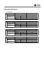
Piping Specifications
60Hz Heat pump
Connection Pipe
Model
Max Distance
Gas Pipe (mm)
ij6
ij9.52
ij9.52
15
Length (m)
30
15
30
4MXW5518A1000AA 4TXK5518A1000AA 4MXW5524A1000AA 4TXK5524A1000AA
7.6
Gas additional charge(g/m)
20
Liquid Pipe (mm)
Max Distance
ij6
Height (m)
Length (m)
Outer Diameter
20
20
Liquid Pipe (mm)
Outer Diameter
7.6
7.6
Gas additional charge(g/m)
Model
Connection Pipe
4MXW5509A1000AA 4TXK5509A1000AA 4MXW5512A1000AA 4TXK5512A1000AA
Length (m)
Gas Pipe (mm)
7.6
20
ij6
ij6
ij12
ij12
Height (m)
20
Length (m)
40
20
40
60Hz Cooling only
Connection Pipe
Model
7.6
Gas additional charge(g/m)
15
Liquid Pipe (mm)
Outer Diameter
Max Distance
Model
Connection Pipe
4MYW5509A1000AA 4TYK5509A1000AA 4MYW5512A1000AA 4TYK5512A1000AA
Length (m)
Gas Pipe (mm)
ij6
ij9.52
ij9.52
15
Length (m)
30
15
30
4MYW5518A1000AA 4TYK5518A1000AA 4MYW5524A1000AA 4TYK5524A1000AA
7.6
Gas additional charge(g/m)
15
Liquid Pipe (mm)
Max Distance
15
ij6
Height (m)
Length (m)
Outer Diameter
7.6
Gas Pipe (mm)
7.6
15
ij6
ij6
ij12
ij12
20
40
Height (m)
20
Length (m)
40
13
Piping Specifications
50Hz Heat pump
Connection Pipe
Model
4MXW5509AB000AA 4TXK5509AB000AA 4MXW5512AB000AA 4TXK5512AB000AA
Length (m)
5
5
Gas additional charge(g/m)
15
15
Outer Diameter
Max Distance
Height (m)
Length (m)
Model
Connection Pipe
Liquid Pipe (mm)
Gas Pipe (mm)
ij6(1/4”)
ij6(1/4”)
ij9.52(3/8”)
ij9.52(3/8”)
15
30
15
30
4MXW5518AB000AA 4TXK5518AB000AA 4MXW5524AB000AA 4TXK5524AB000AA
Length (m)
5
Gas additional charge(g/m)
Outer Diameter
20
Liquid Pipe (mm)
20
ij6(1/4”)
ij6(1/4”)
Height (m)
ij9.52(3/8”)
20
ij9.52(3/8”)
20
Length (m)
40
40
Gas Pipe (mm)
Max Distance
5
50Hz Cooling only
Connection Pipe
Model
4MYW5509AB000AA 4TYK5509AB000AA 4MYW5512AB000AA 4TYK5512AB000AA
Length (m)
5
5
Gas additional charge(g/m)
15
15
Outer Diameter
Gas Pipe (mm)
Max Distance
Connection Pipe
Height (m)
Length (m)
Model
14
Liquid Pipe (mm)
ĭ6(1/4”)
ĭ6(1/4”)
ĭ9.52(3/8”)
ĭ9.52(3/8”)
15
30
15
30
4MYW5518AB000AA 4TYK5518AB000AA 4MYW5524AB000AA 4TYK5524AB000AA
Length (m)
5
5
Gas additional charge(g/m)
20
Outer Diameter
Max Distance
Liquid Pipe (mm)
ij6
20
ij6
Gas Pipe (mm)
Height (m)
ij12
20
ij12
20
Length (m)
40
40
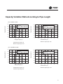
&DSDFLW\9DULDWLRQ5DWLR$FFRUGLQJWR3LSH/HQJWK
)RUMbh models
&RQGLWLRQV
,QGRRU '%&:%&
2XWGRRU '%&:%&
&DSDFLW\UDWLR
&DSDFLW\UDWLR
&RQGLWLRQV
,QGRRU '%&:%&
2XWGRRU '%&:%&
0D[LPXP(OHYDWLRQP
7RWDOSLSHOHQJWKP
7RWDO(OHYDWLRQP
0D[LPXPSLSHOHQJWKP
6WDQGDUGSLSHOHQJWKP
0D[LPXPSLSHOHQJWKP
)RUMbh models
&RQGLWLRQV
,QGRRU '%&:%&
2XWGRRU '%&:%&
&DSDFLW\UDWLR
&DSDFLW\UDWLR
&RQGLWLRQV
,QGRRU '%&:%&
2XWGRRU '%&:%&
7RWDOSLSHOHQJWKP
6WDQGDUGSLSHOHQJWKP
0D[LPXP(OHYDWLRQP
7RWDO(OHYDWLRQP
0D[LPXPSLSHOHQJWKP
0D[LPXPSLSHOHQJWKP
15
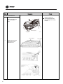
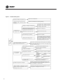
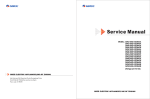
System Diagram
(1)Cooling Only Models
INDOOR UNIT
OUTDOOR UNIT
GAS SIDE
3-WAY VALVE
Muffler
Discharge
HEAT
EXCHANGE
(EVAPORATOR)
Suction
Accumlator
COMPRESSOR
HEAT
EXCHANGE
(CONDENSER)
LIQUID SIDE
2-WAY VALVE
Strainer
Capillary
Strainer
COOLING
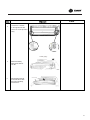
(2)Cooling & Heating Models
INDOOR UNIT
OUTDOOR UNIT
GAS SIDE
3-WAY VALVE
4-Way valve
Muffler
Discharge
HEAT
EXCHANGE
(EVAPORATOR)
Suction
Accumlator
COMPRESSOR
HEAT
EXCHANGE
(CONDENSER)
LIQUID SIDE
3-WAY VALVE
Strainer
Capillary
Strainer
COOLING
HEATING
Refrigerant pipe diameter
Liquid : 1/4" (6 mm)
Gas : 3/8" (9.52 mm)
16
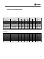
Electrical Characteristics
60Hz Models
Model
Power Supply
Current
OMF
Indoor
Outdoor
Hz
Voltage
Min.
Max.
MCA
MFA
W
FLA
4MXW5509A1
4TXK5509A1
60Hz
220V
198V
242V
8.1
15
21
0.17
4MXW5512A1
4TXK5512A1
60Hz
220V
198V
242V
8.1
15
21
0.17
4MXW5518A1
4TXK5518A1
60Hz
220V
198V
242V
11.6
25
60
0.58
4MXW5524A1
4TXK5524A1
60Hz
220V
198V
242V
11.6
25
60
0.58
4MYW5509A1
4TYK5509A1
60Hz
220V
198V
242V
8.1
15
21
0.17
4MYW5512A1
4TYK5512A1
60Hz
220V
198V
242V
8.1
15
21
0.17
4MYW5518A1
4TYK5518A1
60Hz
220V
198V
242V
11.6
25
60
0.58
4MYW5524A1
4TYK5524A1
60Hz
220V
198V
242V
11.6
25
60
0.58
Outdoor
4TXK5509AB
4TXK5512AB
4TXK5518AB
4TXK5524AB
4TYK5509AB
4TYK5512AB
4TYK5518AB
4TYK5524AB
Hz
50Hz
50Hz
50Hz
50Hz
50Hz
50Hz
50Hz
50Hz
Power Supply
Voltage Min.
220V
198V
220V
198V
220V
198V
220V
198V
220V
198V
220V
198V
220V
198V
220V
198V
Max.
242V
242V
242V
242V
242V
242V
242V
242V
Current
MCA
MFA
8.1
15
8.1
15
11.6
25
11.6
25
6.8
15
6.8
15
11.6
25
11.6
25
W
30
30
60
60
30
30
60
60
OMF
FLA
0.23
0.23
0.58
0.58
0.23
0.23
0.58
0.58
50Hz Models
Model
Indoor
4MXW5509AB
4MXW5512AB
4MXW5518AB
4MXW5524AB
4MYW5509AB
4MYW5512AB
4MYW5518AB
4MYW5524AB
17
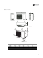
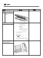
'LPHQVLRQV
,QGRRU8QLWV
:
'
+
'LPHQVLRQVPP
8QLW
MXW5509A
: ZLGWK
770
+ KHLJKW
283
201
MXW5512A 770
283
201
MXW5518A 865
305
215 MXW5524A 319
18
' GHSWK
321
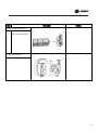
2XWGRRU8QLWV
$
&
%
'
(
8QLWPP
%ROW
1XW
:UHQFK
'LPHQVLRQVPP
8QLW
$ZLGWK
7;.$
7;.$
7;.$
7;.$
%KHLJKW
&GHSWK
'
(
19
&DSDFLW\7DEOHV
Model
SUMMER
Indoor conditions
21ć D 15ć W
24ć D 17ć W
27ć D 19ć W
32ć D 23ć W
25ć
9025
6770
647
54
9588
7142
665
54
10161
7660
677
54
10421
7712
683
54
Total Capacity (Btu/h)
Input (W)
Compressor Frequency (Hz)
Total Capacity (Btu/h)
Input (W)
Compressor Frequency (Hz)
Total Capacity (Btu/h)
Input (W)
Compressor Frequency (Hz)
Total Capacity (Btu/h)
Input (W)
Compressor Frequency (Hz)
OUTDOOR TEMPERATURE DRY
12ć D 7ć D 4ć D 0ć D -4ć D
11ć W 6ć W 3ć W -1ć W -6ć W
11436 10308 12106 12854 11282
736
610
894
1190
1159
57
57
57
57
57
10418 9279 11662 12571 11204
765
644
928
1221
1185
57
57
57
57
57
10209 8900 11457 12431 11101
771
650
939
1230
1194
57
57
57
57
57
9679
8685 10893 12106 11193
808
659
989
1281
1235
57
57
57
57
57
Indoor conditions
18ć
20ć
22ć
20
OUTDOOR TEMPERATURE DRY
30ć
35ć
40ć
45ć
8636 7879
7159
7903
6572 6084
5606
6275
684
703
797
1026
54
54
54
54
9240 8575
7742
8687
6947 6507
5930
6715
695
729
815
1052
54
54
54
54
9721 8800
8455
9281
7408 7067
6579
7295
715
760
855
1087
54
54
54
54
10540 9984
9619 10438
7957 7688
7551
8350
723
785
884
1172
54
54
54
54
Total Capacity (Btu/h)
Sensible Capacity (Btu/h)
Input (W)
Compressor Frequency (Hz)
Total Capacity (Btu/h)
Sensible Capacity (Btu/h)
Input (W)
Compressor Frequency (Hz)
Total Capacity (Btu/h)
Sensible Capacity (Btu/h)
Input (W)
Compressor Frequency (Hz)
Total Capacity (Btu/h)
Sensible Capacity (Btu/h)
Input (W)
Compressor Frequency (Hz)
WINTER
15ć
4MYW5509A1/4TYK5509A1
4MXW5509A1/4TXK5509A1
50ć
7643
6152
1119
54
8319
6490
1147
54
8462
6719
1172
54
9936
8097
1238
54
-7ć D
-8ć W
10021
1142
57
9621
1165
57
9679
1167
57
9563
1240
57
Model
Total Capacity (Btu/h)
Sensible Capacity (Btu/h)
Input (W)
Compressor Frequency (Hz)
Total Capacity (Btu/h)
Sensible Capacity (Btu/h)
Input (W)
Compressor Frequency (Hz)
Total Capacity (Btu/h)
Sensible Capacity (Btu/h)
Input (W)
Compressor Frequency (Hz)
Total Capacity (Btu/h)
Sensible Capacity (Btu/h)
Input (W)
Compressor Frequency (Hz)
25ć
9230
6924
681
54
9806
7304
700
54
10392
7834
713
54
10658
7887
719
54
OUTDOOR TEMPERATURE DRY
30ć
35ć
40ć
45ć
8832 8058
7321
8082
6721 6222
5734
6418
720
740
839
1080
54
54
54
54
9450 8770
7918
8885
7105 6655
6065
6868
731
767
858
1108
54
54
54
54
9942 9000
8648
9492
7576 7227
6728
7461
753
800
900
1145
54
54
54
54
10780 10211 9838 10675
8138 7862
7723
8539
761
826
931
1233
54
54
54
54
50ć
7817
6292
1178
54
8508
6637
1207
54
8655
6871
1233
54
10162
8281
1303
54
Total Capacity (Btu/h)
Input (W)
Compressor Frequency (Hz)
Total Capacity (Btu/h)
Input (W)
Compressor Frequency (Hz)
Total Capacity (Btu/h)
Input (W)
Compressor Frequency (Hz)
Total Capacity (Btu/h)
Input (W)
Compressor Frequency (Hz)
OUTDOOR TEMPERATURE DRY
12ć D 7ć D 4ć D 0ć D -4ć D
11ć W 6ć W 3ć W -1ć W -6ć W
15419 13899 16323 17332 15212
1076
892
1306
1739
1693
57
57
57
57
57
14046 12512 15724 16949 15106
1118
942
1356
1785
1732
57
57
57
57
57
13765 12000 15447 16760 14968
1126
950
1373
1797
1745
57
57
57
57
57
13051 11710 14687 16323 15092
1180
962
1445
1872
1806
57
57
57
57
57
-7ć D
-8ć W
13512
1670
57
12972
1703
57
13051
1706
57
12894
1813
57
SUMMER
Indoor conditions
21ć D 15ć W
24ć D 17ć W
27ć D 19ć W
32ć D 23ć W
WINTER
Indoor conditions
15ć
18ć
20ć
22ć
4MYW5509AB/4TYK5509AB
4MXW5509AB/4TXK5509AB
21
Model
SUMMER
Indoor conditions
21ć D 15ć W
24ć D 17ć W
27ć D 19ć W
32ć D 23ć W
4MYW5512A1/4TYK5512A1
4MXW5512A1/4TXK5512A1
Total Capacity (Btu/h)
Sensible Capacity (Btu/h)
Input (W)
Compressor Frequency (Hz)
Total Capacity (Btu/h)
Sensible Capacity (Btu/h)
Input (W)
Compressor Frequency (Hz)
Total Capacity (Btu/h)
Sensible Capacity (Btu/h)
Input (W)
Compressor Frequency (Hz)
Total Capacity (Btu/h)
Sensible Capacity (Btu/h)
Input (W)
Compressor Frequency (Hz)
25ć
11672
8287
920
74
12548
9184
928
74
13347
9727
929
74
13753
9352
1032
74
Total Capacity (Btu/h)
Input (W)
Compressor Frequency (Hz)
Total Capacity (Btu/h)
Input (W)
Compressor Frequency (Hz)
Total Capacity (Btu/h)
Input (W)
Compressor Frequency (Hz)
Total Capacity (Btu/h)
Input (W)
Compressor Frequency (Hz)
12ć D
11ć W
14609.8
922
68
13932
941
68
13721
958
68
13237
962
68
WINTER
Indoor conditions
15ć
18ć
20ć
22ć
22
OUTDOOR TEMPERATURE DRY
30ć
35ć
40ć
45ć
50ć
11081 10389 9297
8645
8093
8072 7762
7117
6779
6496
1020 1113
1256
1365
1485
74
74
74
74
74
11948 11184 10437 9706
9034
8912 8499
8079
7649
7247
1031 1126
1263
1374
1510
74
74
74
74
74
12927 11600 11269 10665 9594
9590 8792
8662
8338
7629
1036 1130
1257
1388
1503
74
74
74
74
74
13688 13408 13006 12815 12020
9689 9867
9935 10150 9857
1128 1206
1359
1445
1570
74
74
74
74
74
OUTDOOR TEMPERATURE DRY
7ć D 4ć D 0ć D -4ć D
6ć W 3ć W -1ć W -6ć W
13077 11456 12575 11483
915
908
1271
1300
68
68
68
68
12421 11154 12130 11266
930
915
1322
1383
68
68
68
68
12200 10921 11961 11121
940
920
1335
1379
68
68
68
68
11728 10468 11251 10827
952
937
1374
1397
68
68
68
68
-7ć D
-8ć W
10785
1347
68
10613
1426
68
10519
1456
68
10344
1499
68
Model
SUMMER
Indoor conditions
21ć D 15ć W
24ć D 17ć W
27ć D 19ć W
32ć D 23ć W
4MYW5512AB/4TYK5512AB
4MXW5512AB/4TXK5512AB
Total Capacity (Btu/h)
Sensible Capacity (Btu/h)
Input (W)
Compressor Frequency (Hz)
Total Capacity (Btu/h)
Sensible Capacity (Btu/h)
Input (W)
Compressor Frequency (Hz)
Total Capacity (Btu/h)
Sensible Capacity (Btu/h)
Input (W)
Compressor Frequency (Hz)
Total Capacity (Btu/h)
Sensible Capacity (Btu/h)
Input (W)
Compressor Frequency (Hz)
25ć
12074
8573
896
74
12981
9501
904
74
13807
10062
905
74
14227
9674
1004
74
Total Capacity (Btu/h)
Input (W)
Compressor Frequency (Hz)
Total Capacity (Btu/h)
Input (W)
Compressor Frequency (Hz)
Total Capacity (Btu/h)
Input (W)
Compressor Frequency (Hz)
Total Capacity (Btu/h)
Input (W)
Compressor Frequency (Hz)
12ć D
11ć W
17364
1158
68
16559
1181
68
16308
1202
68
15733
1207
68
WINTER
Indoor conditions
15ć
18ć
20ć
22ć
OUTDOOR TEMPERATURE DRY
30ć
35ć
40ć
45ć
50ć
11464 10747 9618
8944
8372
8351 8029
7362
7013
6720
993
1083
1223
1329
1446
74
74
74
74
74
12360 11569 10796 10041 9346
9219 8792
8358
7913
7496
1003 1096
1230
1337
1470
74
74
74
74
74
13373 12000 11658 11033 9925
9921 9095
8961
8626
7892
1008 1100
1224
1351
1463
74
74
74
74
74
14160 13871 13454 13256 12434
10024 10207 10278 10500 10196
1098 1174
1323
1407
1528
74
74
74
74
74
OUTDOOR TEMPERATURE DRY
7ć D 4ć D 0ć D -4ć D
6ć W 3ć W -1ć W -6ć W
15542 13616 14946 13648
1148 1139
1595
1632
68
68
68
68
14762 13257 14417 13390
1168 1148
1659
1736
68
68
68
68
14500 12980 14216 13217
1180 1155
1675
1731
68
68
68
68
13939 12441 13372 12869
1195 1176
1725
1754
68
68
68
68
-7ć D
-8ć W
12818
1691
68
12613
1790
68
12502
1828
68
12294
1882
68
23
Model
Total Capacity (Btu/h)
Sensible Capacity (Btu/h)
Input (W)
Compressor Frequency (Hz)
Total Capacity (Btu/h)
Sensible Capacity (Btu/h)
Input (W)
Compressor Frequency (Hz)
Total Capacity (Btu/h)
Sensible Capacity (Btu/h)
Input (W)
Compressor Frequency (Hz)
Total Capacity (Btu/h)
Sensible Capacity (Btu/h)
Input (W)
Compressor Frequency (Hz)
25ć
17835
13000
1263
68
18708
13563
1287
68
19862
14259
1402
68
20998
15013
1508
68
OUTDOOR TEMPERATURE DRY
30ć
35ć
40ć
45ć
17033 16078 14976 13652
12655 12123 11546 10676
1393 1508
1630
1754
68
68
68
68
17975 17050 16166 15143
13249 12720 12335 11690
1530 1603
1698
1796
68
68
68
68
19063 18200 17562 16634
13972 13645 13208 12676
1520 1660
1786
1897
68
68
68
68
20203 19602 19172 18521
14566 14252 14054 13686
1682 1763
1917
1979
68
68
68
68
Total Capacity (Btu/h)
Input (W)
Compressor Frequency (Hz)
Total Capacity (Btu/h)
Input (W)
Compressor Frequency (Hz)
Total Capacity (Btu/h)
Input (W)
Compressor Frequency (Hz)
Total Capacity (Btu/h)
Input (W)
Compressor Frequency (Hz)
12ć D
11ć W
22289
2267
82
21610
2286
82
21250
2305
82
20854
2344
82
OUTDOOR TEMPERATURE DRY
7ć D 4ć D 0ć D -4ć D
6ć W 3ć W -1ć W -6ć W
20078 19294 16405 15236
2132 1931
1841
1722
82
82
82
82
19849 18879 15846 14856
2168 1958
1846
1747
82
82
82
82
19500 18492 15211 14197
2110 1990
1860
1754
82
82
82
82
19228 18037 14801 13713
2116 2038
1882
1793
82
82
82
82
SUMMER
Indoor conditions
21ć D 15ć W
24ć D 17ć W
27ć D 19ć W
32ć D 23ć W
4MYW5518A1/4TYK5518A1
4MXW5518A1/4TXK5518A1
WINTER
Indoor conditions
15ć
18ć
20ć
22ć
24
50ć
12655
10100
1878
68
14068
11001
1898
68
15713
12147
2010
68
17651
13150
2062
68
-7ć D
-8ć W
14240
1722
82
13693
1728
82
13407
1736
82
13037
1759
82
Model
SUMMER
Indoor conditions
21ć D 15ć W
24ć D 17ć W
27ć D 19ć W
32ć D 23ć W
Total Capacity (Btu/h)
Sensible Capacity (Btu/h)
Input (W)
Compressor Frequency (Hz)
Total Capacity (Btu/h)
Sensible Capacity (Btu/h)
Input (W)
Compressor Frequency (Hz)
Total Capacity (Btu/h)
Sensible Capacity (Btu/h)
Input (W)
Compressor Frequency (Hz)
Total Capacity (Btu/h)
Sensible Capacity (Btu/h)
Input (W)
Compressor Frequency (Hz)
4MYW5518AB/4TYK5518AB
4MXW5518AB/4TXK5518AB
25ć
17717
12914
1217
68
18585
13474
1241
68
19731
14165
1351
68
20859
14914
1453
68
OUTDOOR TEMPERATURE DRY
30ć
35ć
40ć
45ć
16921 15972 14877 13562
12572 12043 11470 10606
1343 1453
1571
1691
68
68
68
68
17856 16938 16060 15043
13162 12636 12253 11613
1475 1545
1636
1732
68
68
68
68
18938 18080 17446 16524
13880 13555 13121 12592
1465 1600
1721
1829
68
68
68
68
20070 19473 19046 18399
14470 14158 13962 13596
1621 1699
1848
1908
68
68
68
68
50ć
12572
10033
1810
68
13975
10928
1830
68
15609
12067
1937
68
17534
13063
1988
68
12ć D
11ć W
22230
1695
82
21553
1710
82
21193
1724
82
20799
1753
82
OUTDOOR TEMPERATURE DRY
7ć D 4ć D 0ć D -4ć D
6ć W 3ć W -1ć W -6ć W
20025 19242 16361 15196
1594 1444
1376
1288
82
82
82
82
19796 18828 15804 14816
1621 1464
1380
1306
82
82
82
82
19448 18443 15170 14159
1578 1488
1391
1312
82
82
82
82
19177 17989 14762 13676
1583 1524
1407
1341
82
82
82
82
-7ć D
-8ć W
14202
1288
82
13656
1292
82
13371
1299
82
13002
1316
82
WINTER
Indoor conditions
15ć
18ć
20ć
22ć
Total Capacity (Btu/h)
Input (W)
Compressor Frequency (Hz)
Total Capacity (Btu/h)
Input (W)
Compressor Frequency (Hz)
Total Capacity (Btu/h)
Input (W)
Compressor Frequency (Hz)
Total Capacity (Btu/h)
Input (W)
Compressor Frequency (Hz)
25
Model
SUMMER
Indoor conditions
21ć D 15ć W
24ć D 17ć W
27ć D 19ć W
32ć D 23ć W
Total Capacity (Btu/h)
Sensible Capacity (Btu/h)
Input (W)
Compressor Frequency (Hz)
Total Capacity (Btu/h)
Sensible Capacity (Btu/h)
Input (W)
Compressor Frequency (Hz)
Total Capacity (Btu/h)
Sensible Capacity (Btu/h)
Input (W)
Compressor Frequency (Hz)
Total Capacity (Btu/h)
Sensible Capacity (Btu/h)
Input (W)
Compressor Frequency (Hz)
WINTER
Indoor conditions
15ć
18ć
20ć
22ć
26
Total Capacity (Btu/h)
Input (W)
Compressor Frequency (Hz)
Total Capacity (Btu/h)
Input (W)
Compressor Frequency (Hz)
Total Capacity (Btu/h)
Input (W)
Compressor Frequency (Hz)
Total Capacity (Btu/h)
Input (W)
Compressor Frequency (Hz)
4MYW5524A1/4TYK5524A1
4MXW5524A1/4TXK5524A1
OUTDOOR TEMPERATURE DRY
30ć
35ć
40ć
45ć
19694 18538 17253 15899
14672 14089 13372 12560
2127 2296
2447
2602
84
84
84
84
21003 19923 18573 17140
15354 14682 13801 12838
2141 2339
2486
2641
84
84
84
84
22995 22100 20561 19015
17061 16584 15583 14565
2176 2380
2527
2686
84
84
84
84
24702 24297 23656 22563
17661 17736 17623 17147
2202 2416
2593
2773
84
84
84
84
50ć
13537
10897
2435
84
14925
11268
2448
84
15799
12228
2473
84
19457
15080
2609
84
OUTDOOR TEMPERATURE DRY
12ć D 7ć D 4ć D 0ć D -4ć D
11ć W 6ć W 3ć W -1ć W -6ć W
29608.9 27946 25531 21706 19742
2811
2637 2505
2405
2332
100
100
100
100
100
28874 27340 25590 21592 19537
2825
2677 2529
2422
2329
100
100
100
100
100
28639 27000 25285 21325 19295
2852
2720 2575
2454
2339
100
100
100
100
100
27184 26789 24447 20334 19038
2809
2703 2639
2502
2391
100
100
100
100
100
-7ć D
-8ć W
19108
2199
100
19319
2224
100
19083
2280
100
18622
2291
100
25ć
20561
15011
1848
84
22453
16279
1882
84
23660
17366
1913
84
24428
17099
1938
84
Model
Total Capacity (Btu/h)
Sensible Capacity (Btu/h)
Input (W)
Compressor Frequency (Hz)
Total Capacity (Btu/h)
Sensible Capacity (Btu/h)
Input (W)
Compressor Frequency (Hz)
Total Capacity (Btu/h)
Sensible Capacity (Btu/h)
Input (W)
Compressor Frequency (Hz)
Total Capacity (Btu/h)
Sensible Capacity (Btu/h)
Input (W)
Compressor Frequency (Hz)
25ć
20474
14948
1541
84
22359
16211
1570
84
23560
17293
1595
84
24325
17027
1616
84
OUTDOOR TEMPERATURE DRY
30ć
35ć
40ć
45ć
19611 18460 17180 15832
14610 14030 13316 12507
1774 1915
2041
2170
84
84
84
84
20915 19839 18494 17068
15289 14620 13743 12784
1786 1951
2073
2202
84
84
84
84
22898 22007 20474 18935
16989 16515 15518 14504
1814 1985
2108
2240
84
84
84
84
24598 24195 23557 22468
17586 17662 17549 17074
1836 2015
2163
2313
84
84
84
84
50ć
13480
10852
2031
84
14862
11220
2042
84
15733
12176
2063
84
19375
15016
2176
84
Total Capacity (Btu/h)
Input (W)
Compressor Frequency (Hz)
Total Capacity (Btu/h)
Input (W)
Compressor Frequency (Hz)
Total Capacity (Btu/h)
Input (W)
Compressor Frequency (Hz)
Total Capacity (Btu/h)
Input (W)
Compressor Frequency (Hz)
12ć D
11ć W
26192
1995
100
25542
2004
100
25334
2024
100
24046
1993
100
OUTDOOR TEMPERATURE DRY
7ć D 4ć D 0ć D -4ć D
6ć W 3ć W -1ć W -6ć W
24721 22585 19201 17463
1871 1778
1707
1655
100
100
100
100
24184 22637 19100 17282
1900 1794
1718
1652
100
100
100
100
23884 22367 18864 17068
1930 1827
1741
1660
100
100
100
100
23697 21625 17987 16841
1918 1873
1776
1696
100
100
100
100
-7ć D
-8ć W
16902
1561
100
17089
1578
100
16881
1618
100
16473
1625
100
SUMMER
Indoor conditions
21ć D 15ć W
24ć D 17ć W
27ć D 19ć W
32ć D 23ć W
4MYW5524AB/4TYK5524AB
4MXW5524AB/4TXK5524AB
WINTER
Indoor conditions
15ć
18ć
20ć
22ć
27
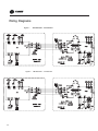
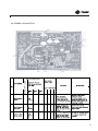
:LULQJ'LDJUDPV
)LJXUH
)LJXUH
28
4MYW5509A14TYK5509A1
4MYW5512A1 4TYK5512A1
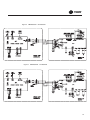
)LJXUH 4MYW5518A1 4TYK5518A1
)LJXUH4 4MYW5524A1 4TYK5524A1
29
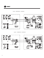
)LJXUH5 4MXW5509A14TXK5509A1
)LJXUH6
30
4MXW5512A14TXK5512A1
)LJXUH7 4MXW5518A1 4TXK5518A1
)LJXUH8 4MXW5524A1 4TXK5524A1
31
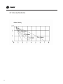
$LU9 HOR FLW\'LVWULEXWLRQ
32
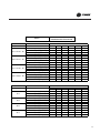
Sound Level
Test condition
Test value
60Hz models
Model
Unit
Number
Outdoor
4TXK5509A1
4TXK5512A1
4TXK5518A1
4TXK5524A1
4TYK5509A1
4TYK5512A1
4TYK5518A1
4TYK5524A1
1
2
3
4
7
8
9
10
Indoor
4MXW5509A1
4MXW5512A1
4MXW5518A1
4MXW5524A1
4MYW5509A1
4MYW5512A1
4MYW5518A1
4MYW5524A1
Indoor Sound Pressure level (dB(A))
SH
H
M
L
32
43
38
26
44
33
39
28
34
48
43
38
43
49
39
34
32
43
38
26
44
39
28
33
48
43
38
34
49
43
39
34
Indoor
4MXW5509AB
4MXW5512AB
4MXW5518AB
4MXW5524AB
4MYW5509AB
4MYW5512AB
4MYW5518AB
4MYW5524AB
Indoor Sound Pressure level (dB(A))
SH
H
M
L
36
30
24
43
44
37
31
25
40
37
32
45
42
37
32
46
36
30
24
/
37
31
25
/
40
37
32
45
46
42
37
32
50Hz models
Unit
Number
1
2
3
4
5
6
7
8
Model
Outdoor
4TXK5509AB
4TXK5512AB
4TXK5518AB
4TXK5524AB
4TYK5509AB
4TYK5512AB
4TYK5518AB
4TYK5524AB
33
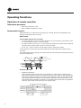
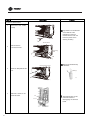
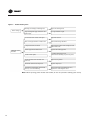
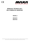
Operating Functions
Operation of remote controller
Temperature parameters
•
Room set temperature (T set)
•
Room ambient temperature (T amb)
Fundamental functions
After powered on, no matter when the compressor is started, the time interval between two
startups cannot be less than 3 minutes.
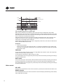
COOL mode
The condition and process of cooling
•
If T amb is superior or equal T set, COOL mode will act, the compressor and outdoor fan will
run, and the indoor fan will run at the set speed.
•
If T amb is inferior or equal T set -2 ºC, the compressor will stop, the outdoor fan will delay 30
seconds to stop, and the indoor fan will run at the set speed.
•
If T set -2ºC < T amb < Tset, the unit will keep running in the previous mode.
In this mode, the reversal valve will not be powered on and the temperature setting range is
16ºC~30ºC.
The unit will adjust the running frequency of the compressor automatically according to the change
of ambient temperature.
Tset
Start cooling
Tamd
Original running state
Tset
Stop cooling
3min
Compressor
Outdoor fan
Set fan speed
Indoor fan
Run
Stop
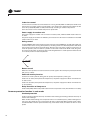
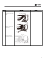
Protection function
•
Antifreezing protection
Under cooling and drying mode, after the compressor run about 10 mins, when the pipe
temp.of the evaporator is to low, the compressor will stop, the outdoor fan will stop after 30s,
under cooling mode the indoor fan and swing motor will keep running in the original mode,
under drying mode the indoor fan will run at low fan speed, the swing motor will run in the
original mode. When antifreezing protection is eliminated and the compressor has stopped for
3 minutes, the unit will resume running in the original mode.
The period of antifreezing protection
Compressor
3 min
Outdoor fan
Indoor fan
Run
34
Stop
Overcurrent protection
If total current is high, the compressor will run in limited or dropped frequency. When total current
goes on rising over the stated value, the compressor will stop, the outdoor fan will delay 30 seconds
to stop.
DRY mode
The condition and process of drying
•
If T amb > T set, DRY mode will act, the indoor fan, outdoor fan and compressor will run, and
indoor fan will run at low speed.
•
If T set -2ºC inferior or equal T amb inferior or equal T set, the unit will keep running in the
original mode.
•
If T amb < T set -2ºC, the compressor will stop running, the outdoor fan will delay 30 seconds
to stop and the indoor fan will run at low speed.
In this mode, the reversal valve will not be powered on and the temperature setting range is
16ºC~30ºC.
The unit will adjust the running frequency of the compressor automatically according to the change
of ambient temperature.
Tamb
Dry mode will act
Tset
Running in the original mode
Tset-2
Stop running
Compressor
Outdoor fan
Indoor fan
Low fan speed
Run
Stop
Protection
Protection is the same with that in COOL mode.
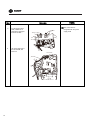
HEAT mode
The condition and process of heating
•
If T amb inferior or equal T set +2ºC, HEAT mode will act, the compressor, outdoor fan and 4way valve will run simultaneously, the indoor fan will delay at most for 2min to run.
•
If T set +2ºC < Tamb < Tset +5ºC, the unit will keep running in the original mode.
•
If T amb superior or equal T set +5ºC, the compressor will stop, the outdoor fan will delay 30
sec to stop and the indoor fan will blow for 60 sec at the original speed and then stop.
In this mode, the temperature setting range is 16ºC~30ºC.
The air conditioner will adjust the running frequency of the compressor automatically according
to the change of ambient temperature.
When the unit is turned off in HEAT mode, or switched to other mode from HEAT mode, the fourway valve will be powered off 2min later after the compressor stops.
35
Stop heating
Tset
Original running state
Tset
Tamb
Start heating
3min
Compressor
Outdoor fan
Indoor fan
2min
2min
Reversal valve
Run
Stop
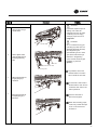
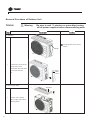
The condition and process of defrosting
When frost is detected in the condenser, the system will enter into defrosting state. When
defrosting starts, the compressor and indoor fan will stop, and the outdoor fan and four-way valve
will delay 30 seconds to stop. The compressor will start again after 30s and. When the compressor
has run for 8mins, the compressor will stop.
After 30 seconds the four-way valve opens and after another 60 seconds, the compressor and
outdoor fan resume running. The indoor fan will delay 2 minutes to run at the latest and
temperature on the display panel shows H1.
Under heating mode,when the compressor is stopped by malfunction, the indoor fan will blow at
low fan speed for 60s and then stop.
Protection
•
Overcurrent protection
If total current is high, the compressor will run in limited or dropped frequency. When total
current go on rising over the stated value, the compressor will stop, the outdoor fan will delay
30 seconds to stop.
FAN mode
In this mode, the indoor fan will run the fan in High, Med, Low and Auto mode. The compressor,
outdoor fan and four-way valve will stop.
In this mode, the temperature setting range is 16~30ºC.
The unit will adjust the running frequency of the compressor automatically according to the change
of ambient temperature.
AUTO mode
In this mode, the system selects COOL, HEAT and FAN mode automatically according to the change
of ambient temperature. The protection function is the same with that of COOL/HEAT mode.
The unit will adjust the running frequency of the compressor automatically according to the change
of ambient temperature.
Other control
ON / OFF
Each time the On/Off button of the remote controller is pressed, the On/Off state will switch once.
MODE selection
Press the MODE button on the remote controller to select and display the following modes: AUTO,
COOL, DRY, FAN, and HEAT.
36
TEMP. setting button
Each time TEMP + or TEMP - button is pressed, the set temperature will be increased or decreased
by 1ºC.
Adjusting range is 16~30ºC . In AUTO mode, this button does not function.
AUTO key
When the unit is stop, press AUTO key, the unit will run under AUTO mode and the swing motor
starts.
When the unit is running, press AUTO key, the unit will be stopped.
AUTO/STOP
Handling switch
Timer control
The unit is turned on or off according to the timer set by the remote controller.
Sleep control
When the air conditioner is in COOL or DRY mode, after Sleep mode has been set properly, the
preset Tset will be increased by 1ºC after the sleep program has run for 1 hour, and Tset will be
increased by another 1ºC after 2 hours. Tset has been increased by 2ºC total in two hours. Then the
unit will run at this set temperature and at the set speed.
Tset+2
Set temp.Tset
Tset+1
Tset
1h
2h
Above 2h
When the air conditioner is in HEAT mode, after Sleep mode has been set properly, the preset Tset
will be decreased by 1ºC after the sleep program has run for 1 hour, and Tset will be decreased by
another 1ºC after 2 hours. Tset has been increased by 2ºC totally in two hours. Then the unit will
run at this set temperature and at the set speed.
1h
2h
Above 2h
Tset
Tset-1
Tset-2
Set temp.Tset
In AUTO or FAN mode, the setting temp. will not change.
37
Indoor fan control
Use the remote controller to set the indoor fan running at HIGH, MED or LOW speed. At this time
the fan will run at high, medium or low speed. It can also be set to AUTO and the indoor fan will
select fan speed(HIGH, MED or LOW) automatically according to ambient temperature.
There are at least 3 mins and 30s delay for fan speed shift.
Power supply for outdoor unit
The power supply for outdoor unit is turned on in AUTO, COOL, HEAT and DRY mode under turnon state.
The power supply for outdoor unit will delay 3 minutes to turn off under turn-off state or in the FAN
mode under turn-on state.
Swing control
Use the SWING button of the wireless remote control to control SWING On and Off. Swing will only
act when indoor fan is running. After power on, the swing motor turns back to 0 position and closes
the air outlet vent; if it does not preset swing, after the unit is turned on, it will turn to the max. air
outlet D1 position; then turn back to L position under COOL mode.Under HEAT mode, the guide
louver stays at D1; when in swinging state, it will swing between L1 and D1 position. When the unit
is turned off, it will turn back to 0 position.
Buzzer control
When the unit is power on or receives remote control signal or the auto key be pressed, the buzzer
will give out a beep.
Power-off memory function
Contents of memory: Mode; Swing; Set fan speed, Set temperature, Timing etc.
Under turn-on state, when power off and power on, the power supply for outdoor unit will be turn
on after 3 mins.
Under turn-off state, when power off and power on, the power supply for outdoor unit will be turn
on immediately.
Delay Protection of Compressor
Under COOL; DRY; HEAT mode, before each time the compressor starts, there will be 3 mins delay.
Common protection function in each mode
Overload protection
Ttube: at cooling,it detects the temp. of outdoor heat exchanger,at heating,it detects the temp. of
indoor heat exchanger.
When Ttube is detected high, the compressor will run in limited frequency. When Ttube goes on
rising over the stated value, the compressor will stop; under AUTO HEAT or HEAT mode, indoor
fan will blow 60s at low fan speed and then stop; under other mode, the indoor fan will run at set
speed.
38
Compressor discharge temperature protection
When discharge temperature is too high to over the stated value, the compressor will stop, and
When discharge temp. resume normal and the compressor has stopped for 3 minutes, the unit will
resume its original operating status.
Communication malfunction
When not receiving correct signal for 3 minutes, the unit has communication malfunction and the
outdoor unit stops, it is the same as normal stop when meeting the set temp.
Module protection
When module is in protection, the compressor will stop, after the compressor has stopped for 3
minutes, it will resume to running. During module protection period, the indoor unit displays
malfunction and the whole unit stops.
39
'LVDVVHPEO\3URFHGXUHV
Removal Procedure of Indoor Unit
1. External features
If ON/OFF button is kept pushing
for 5 seconds, aforced cooling operation willbe carried out for
approx. 15minutes.
2. Removing air filters
1
Pull protrusions on left
and right sides of panel
with fingers and open
front grille all the way.
2
Lift center section of air
filter and disengage
hooks.
Air filter
Left and right filters are
interchangeable.
To re-install, insert air filter
along the guide.
Hooks
3
Remove air filter by
pulling forward.
40
Support the front panel by one
3. Opening and shuttingfront panel
1
hand, while remove the rotation
axis at the upper center by the
Pull down horizontal blade
by pulling forward.
other hand.
And pull out the front panel
forward to remove.
Horizontal blade
2
Remove horizontal blade by
pulling forward.
3
Hook a finger onto the
projection part provided
on the both sides of the
unit’s panel and open
Left and right filters are
interchangeable.
up the panel to the
position higher than it
To re-install, insert air filter
along the guide.
will stop.
Right
Left
4
Rotary shaft
Rotary shaft
Remove the front panel
from the unit.
41
4. Opening and closing of service cover
1
screws
Remove a service
cover mounting screw.
Open service cover
upward.
A switch for field setting is
not provided in particular.
screws
5. Removal of front grille assembly
1
2
Remove the 3 screws,
in the right and the left,
which fix the main body
Screw stoppers inside the
flap which were equipped in
with the front grille.
the existing models are not
provided.
Disengage the 3 hooks
Hooks
on the upper part.
In case that the hooks
are not pressed from
above, remove the front
panel and then remove
the grille while pushing
the hook through a
clearance between the
front grille and the heat
exchanger.
At the upper part there are 2
Left
Center
Right
hooks in the left and the
right.
Disengage the hooks by
3
The front grille can be
removed in a manner to
pull out the upper part
forward and lift up the
lower part.
42
pressing knobs with a
screwdriver.
6. Remove the Vertical blade
1
Unfasten the hooks at
the upper 2 positions.
Hook
A set of vertical blade has 6
fins as on ASSY.
(It is impossible to replace
only one fin.)
The set of vertical blades is
not marked for difference
between right and left.
2
Unfasten the 3 hooks at
the shaft mounting part
by pressing them with a
flat screwdriver.
Repeat the same procedure
to remove the vertical blade
on the other side.
Hook
3
Remove the vertical
blade.
Vertical blade
43
7. Remove electrical box
1
Disconnect the Cable
clamp
Pay attention to the direction
of the retainer of the
thermistor so that the
retainer will not touch the
harness (same as the
existing models.)
Terminal board
2
Disconnect the
connection wires.
Connecting
wires
Heat exchanger thermistor
3
Remove Temperature Sensor
Take care not to lose the clip
of thermistor.
Clip
Heat exchanger
thermistor
(R11268)
(R11244)
4
Remove a screw on the
terminal board.
Screw
Earth wire
44
The electrical box can be
removed instead of
disengaging the terminal
board.
5
Remove fan motor Signal
Wire
6
Remove a screw on the
electrical box.
7
Pull up the electrical
box forward to remove.
fan motor Signal Wire
Bottom frame
Hook
45
8. Remove the shield plate.
1
Unfasten the hooks at
the upper 2 positions of
the shield plate.
Hook
Remove the electrical box according
to the “Removal of Electrical Box”.
shield plate (1)
2
Unfasten the hook at
the lower position, and
remove the shield plate
(1).
Hook
3
Lift the shield plate (2)
and unfasten the 2
hooks.
Hook
4
Slide the shield plate
(2) and remove it.
Shield plate (2)
46
2
Take off Wiring terminal
Display PCB ASSY
3
Remove Display PCB
Sub-Assy.
4
Remove Swing motor.
Swing motor
47
5
6
The control PCB is
To remove the control
PCB, unfasten the 2
hooks at the upper part
from the rear side.
integrated with the power
supply PCB.
Lift up the upper part of
the control PCB, and
remove it.
Control PCB
48
9. Disconnect the refrigerant piping.
1
CAUTION
If gas leaks, repair the spot of
Lift the indoor unit by a
wooden base.
leaking, then collect all
refrigerant from the unit. After
conducting vacuum drying,
recharge proper amount of
refrigerant.
CAUTION
Wooden base
Do not contaminate any gas
(including air) other than the
specified refrigerant (R-410A)
into refrigerant cycle.
2
(Contaminating of air or other
gas causes abnormal high
Place a plastic sheet
under the drain pan as
remaining drain may
leak.
pressure in refrigerating
cycle, and this results in pipe
Drain hose
breakage or personal
injuries.)
Extension drain hose
Connecting wires
Pay attention so that the
residual water in the drain
will not make the floor wet.
3
Disconnect the flare nut
for gas piping by 2
wrenches.
In case that a drain hose is
buried inside a wall, remove
it after the drain hose in the
wall is pulled out.
4
Disconnect the flare nut
for liquid piping by 2
wrenches.
Use two wrenches to
disconnected pipes.
When disconnecting pipes,
cover every nozzle with caps
so as not to let dust and
moisture in.
49
9. Remove the indoor unit.
1
When the pipings are
disconnected, protect the
both openings from entering
moisture.
Remove the indoor unit
from the installation
plate.
Liquid piping
Gas piping
(R8019)
Auxiliary piping
2
50
Release the hook of the
piping fixture on the
back of the unit.
Piping fixture
3
Loosen the 2 screws,
in the right and the left,
which fix the Evaporator
Assy.
Auxiliary piping
4
Widen the auxiliary
piping to the extent of
10°~20°.
5
Pull the heat exchanger
to the front side to undo
the hooks completely,
and then lift it.
Heat exchanger
51
10. Remove Cross Flow Fan Fan
Motor
1
Remove Cross Flow Fan
Fan Motor
11. Remove Ring of Bearing
Bearing
12. Remove Cross Flow Fan and
Motor Sub-Assy screw.
52
13. Remove Motor Sub-Assy
1
Remove Motor Sub-Assy
14. Remove Fan Motor
53
Removal Procedure of Outdoor Unit
Warning
Be sure to wait 10 minutes or more after turning
off all power supplies before disassembling work.
1. Features
The stop valve cover has 6
hooks.
Handle
1
Loosen the screw of the
stop valve cover.
Pull down the stop valve
Stop
valve
cover
cover and remove
it.
2. Removing air filters
Top panel
1
Loosen the 3 screws
(front, right, left) and lift
the top panel.
54
2
Loosen the 1 screws
and remove the
discharge grille.
Lift the front panel and
3
Loosen the 5 screws of
remove it while pushing the
the front panel.
right side panel inwards.
Step Procedure Points
Front panel.
Remove the 5 screws from
the edge between right-side
board and condenser and from
valve. Lift to remove the right-side
board subassembly.
Remove the fan motor
1
The screw has reverse
winding.
Remove the screws of the fan
by
wren ch and then remove the
propeller fan.
Remove the propeller
Propeller fan.
fan.
55
2
M4×16
Remove the 4 tapping screws
fixing the motor. Pull out the
lead-out wire and remove the
motor. Remove the 2 tapping
screws fixing the motor
support. Lift to remove
the motor support.
Fan motor fixing frane
DC fan motor
Fan motor
5.Remove the electrical box.
Electrical box
1
Remove the 2 screws fixing
the cover of electric box. Lift to
remove the cover. Remove the
screws fixing the electric box
subassembly. Loosen the wire
and disconnect the termina
Lift to remove the electric
box subassembly.
6.Remove the partition plate.
1
Loosen the 2 screws.
The partition plate is fixed to
the bottom frame with a hook.
2
The partition plate has
a hook on the lower
side. Lift and pull the
partition plate to remove.
Partition plate
56
7.Remove the sound blanket.
Since the piping ports on
1
Lift and remove the
the sound blanket are
sound blanket (top).
torn easily, remove the
blanket carefully.
2
Untie the strings and
open the sound blanket.
3
Lift and remove the
sound blanket (body) as
it is opened.
4
Pull the sound blanket
Since the piping ports on
(inner) out.
the sound blanket are
torn easily, remove the
blanket carefully.
Sound blanket.
8.Remove the partition plate.
Provide a protective sheet or
a steel plate so that the
brazing flame cannot
1
Loosen the screw of the
four way valve coil.
influence peripheries.
Be careful so as not to break
the pipes by pressing it
excessively by pliers when
withdrawing it.
Caution
Be careful about the four way
valve, pipes and so on, which
were heated up by a gas
brazing machine, so as not
to get burnt your hands.
57
9.Remove compressor
1
Solder off the welding spot of
capillary and valve and outlet
pipe of condenser.
2
Remove the 2 screws fixing the
gas valve. Solder off the weld
spot connecting gas valve and
air return pipe and remove the
gas valve.
(Note: it is necessary to warp
the gas valve when soldering
off the welding spot.)
Remove the 2 screws fixing
liquid valve. Solder off the
welding spot connecting liquid
valve and remove the liquid valve.
3
Solder off the pipe connected
with the compressor.
4
58
Remove the 3 footing
screws of the compressor
and remove the compressor.
Troubleshooting
WARNING
Hazardous Service Procedures!
The maintenance and troubleshooting procedures recommended in this section of the manual
could result in exposure to electrical, mechanical or other potential safety hazards. Always refer
to the safety warnings provided throughout this manual concerning these procedures. Unless
specified otherwise, disconnect all electrical power including remote disconnect and discharge
all energy storing devices such as capacitors before servicing. Follow proper lockout/tagout
procedures to ensure the power can not be inadvertently energized. When necessary to work
with live electrical components, have a qualified licensed electrician or other individual who has
been trained in handling live electrical components perform these tasks. Failure to follow all of
the recommended safety warnings provided, could result in death or serious injury.
General Section
WARNING
Hazardous Voltage!
Disconnect all electric power, including remote disconnects before servicing. Follow proper
lockout/tagout procedures to ensure the power can not be inadvertently energized. Failure to
disconnect power before servicing could result in death or serious injury.
Figure 5. Air conditioner cannot start up
When the breaker is set ON, it will
trip at once
Measure the insulating resistance
for grounding to confirm whether
there is electrical leakage or short
circuit in the unit
When the unit is turned on, the
breaker will trip in a few minutes
Insulation malfunction of line or componen
in the air conditioner. Insulation breakdow
occurs after radiation, which causes shor
circuit or electricity leakage. Measure
insulating resistance or use one-by-on
elimination method;
Malfunction of fuse. Replace it.
Breaker tripped
or fuse burnt out
Air
conditi
oner
cannot
start up
Air
conditioner
does not response
after powered on.
(The buzzer does
not sound after the
plug is connected
and the unit does
not response after
the
remote
controller is used
to turn it on)
Remote
controller does
not receive signal
(When powered
on, the buzzer
will send out a
sound, unless it is
broken)
No power supply
Check power supply circuit
The power plug is not or poorly
connected
Check and plug well plug, make
loosen contact firm
Controller fuse is burnt out
Change control fuse
Loose or poor contact of transformer
connection, or transformer malfunction
Secure the wire connection: measure
the output voltage of the transformer
and replace it if the value is wrong
The controller is broken
Replace the controller
Batteries of remote controller are low
Change battery
Malfunction of remote controller
Loose or poor connection of receiving
head
Receiving head is broken
First press the "AUTO" button of the
manual switch. If there is no response,
check according to the above method;
if it is normal after the button is
pressed, check if the installation
location and wire connection of the
receiving head are correct. If correct,
replace the receiving head, or the
remote controller.
59
Figure 6. Troubleshooting chart
Improper setting of temperature
Adjust the set temperature
Whether cooling (heating) load
is proper
Check the estimated load of cooling (heating)
Poor cooling
(heating) effect
Malfunction of
refrigerant flow
Leakage or shortage of refrigerant
Vacuumize after leakage detection
and leakage repair. Charge refrigerant
according to specification.
Leakage occurs between high and
low pressure inside compressor
Replace the compressor
Malfunction of four-way valve
Replace the four-way valve
Partial blockage of capillary
Replace the capillary
Blockage of cooling system
Use the method of observing condensation
on the evaporator and pressure value of
high pressure manometer to see whether
the system is blocked and carry out
corresponding handling on the system
Poor thermal insulation of connecting
pipe of indoor and outdoor unit
Air circulation
is insufficient
Ensure that both thick pipe and thin pipe are insulated
well. The exposed part of the connector and copper pipe
must be insulated as well.
Heat exchanger of outdoor unit
is blocked
Clean the dust accumulated on the
surface of the heat exchanger
Air filters are blocked
Clean the filter
Fan speed is set too slow
Set the fan speed to high or medium
speed
Fan speed turns low
Improper installation location
for outdoor unit
60
Damage of
capacitor
damaged
Replace
capacitor
Damage of
motor
Replace the motor
the
Outdoor unit should be installed in a
place with well ventilation
Outdoor temperature is too high
Flashing or awning can be installed appropriately. If the
max. cooling capacity cannot be satisfied, replacement of
the air conditioner is recommended.
Indoor sealability is inadequate; too many
people go in and out frequently; there is
heating unit in the room.
Maintain a certain degree of indoor sealability. Try not to
use appliance with high amount of heat.
Figure 7.
Troubleshooting chart
When unit is
cooling or
heating, both
compressor and
outdoor fan don't
run
When unit is
cooling or
heating, the
compressor runs
but outdoor fan
doesn't run
When cooling or
heating, outdoor
fan runs, but
compressor
doesn't run.
When cooling or
heating, outdoor
fan runs, but
compressor
doesn't run.
Fan doesn't run
when FAN mode
is set
Abnormal power supply of outdoor unit
Check the circuit according to circuit diagram
Damage of outdoor main control board
Replace the main control board
Breakage of outdoor power module
Replace the power module
Improper setting of temperature
Adjust the set temperature
Breakage of outdoor fan motor
Replace the fan motor
Wrong wire connection
Wire according to the circuit diagram
Breakage of outdoor main control board
Replace the main control board
Breakage of outdoor fan capacitor
Replace the fan capacitor
Malfunction of compressor
Replace the compressor
Poor contact of connection between the
main control board and module
Re-fasten the connection
Abnormal input of power module
Check if input is 320V. If not, replace the
rectifier
Abnormal output of power module
Replace the power module
Compressor temperature is too high
Cool the compressor for 30 min before running
Wrong wiring
Wire according to the circuit diagram
Damage of outdoor main control board
Replace the outdoor main control board
Burn-out or broken wire of indoor fan
motor
Repair or change the fan motor
Wrong wiring
Wire according to the circuit diagram
Circuit break or damage of fan motor
capacitor
Replace the indoor main control board
61
Figure 8. Troubleshooting chart
Blockage or breakage of drainage hose
Replace the drainage hose
Wrap of refrigerant pipe connector is not
tight enough
Re-wrap and make it tight
Fan of indoor unit contacts other parts
Adjust fan location
There is foreign substance in indoor unit
Take out the foreign substance
Compressor shakes too much
Adjust support washer of the compressor and
tighten loose bolts
Touch of pipeline of outdoor unit
Separate the touched pipeline
Touch of inner plates
1. Tighten connecting screws
2.Stick shock-absorbing clay between plates
Touch of outdoor unit fan blade with
outer case
Adjust louver position
Abnormal sound inside compressor
Replace compressor
Abnormal electromagnetic sound inside
four-way valve when heating
Short circuit inside electromagnetic valve.
Replace the electromagnetic valve
Water leakage
Abnormal sound
and shake
Note: When replacing power module and rectifier, be sure to spread the radiating paste evenly.
62
Figure 9. Compressor is too hot
Compressor too hot,
just start and stop at
once, or the stop
often occur
Check whether the outdoor unit is not mounted
properly such as outlet blockage; bad ventilation
or directly under sunlight
yes
Change the mounting position
no
yes
Ambient temperature is too high
For safe use
no
Check if the filter or the outdoor condenser dirty
yes
Clean them
no
Check if the indoor and outdoor fans do not run
or run too slowly and whether the outlet airflow
is normal
yes
Check if the power supply circuit for
motor on the controller is normal or
replace the motor
no
Check if the cooling system blockage, the frost
on the capillary don't melt
yes
Replace blockage component
no
The power is abnormal
yes
Add voltahe regulator,etc.
no
Check if the system operating pressure is normal
to confirm whether the refrigerant is leakage or mix
with air (normal: 0.4-0.6MPa for cooling system,
1.6-2.4 MPa for heating system)
yes
Recharge refrigerant
no
Check the breadboards of indoor and outdoor units
and the power supply circuit assembly
yes
Change the assembly or main PCB
no
Check the U ;V; W output of the outdoor power
module for detail, see "Power Module protection"
yes
Change the power module
no
Check if the compressor is jammed or the
wire-wound resistance is open or short circuit
yes
Change the compressor
63
0DOIXQFWLRQ'LVSOD\6HFWLRQ
:KHQPDOIXQFWLRQRUSURWHFWLRQRFFXUVLQWKHDLUFRQGLWLRQHUFRUUHVSRQGLQJFRGHZLOOEHGLVSOD\HG
RQWKHVFUHHQRIWKHLQGRRUXQLWDQGWKHLQGLFDWRURIRXWGRRUXQLWZLOOEOLQNDFFRUGLQJO\DVZHOO
:KHQSURWHFWLRQRUPDOIXQFWLRQLVHOLPLQDWHGGLVSOD\ZLOOEHEDFNWRQRUPDO
0%+DQG+]1R/('OLJKWVRQRXWGRRW3&%
FRGH
PDOIXQFWLRQ
(UURUGLVSOD\
'XDO
5HSDLUPHWKRG
FRGH
PDOIXQFWLRQ
(UURUGLVSOD\
/('
'XDO
GLVSOD\
6WRUDJHVOXJ
,QGRRU
((
3&%
((
PDOIXQFWLRQ
+HDWLQJ
&KHFNLIWKHUHVLVWDQFHRIFRPSUHVVRUDQG
/('SDXVHV
UHVLVWDQFH WR JURXQG LV QRUPDO ,I WKH
DQG EOLQN DQG EOLQN FRPSUHVVRU LV QRUPDO WKH RXWGRRU PDLQ
WLPHV
WLPHV
ERDUGPD\EHZURQJ
&RROLQJ
5HSODFHRXWGRRUPDLQERDUG
5HSODFH LQGRRU
/('SDXVHV
PDLQERDUG
+HDWLQJ
5HSODFH LQGRRU
/('SDXVHV
PDLQERDUG
6\QFIDLOXUH
&XUUHQW
+
GLFWLRQ
PDOIXQFWLRQ
8
/('SDXVHV
RI
DQG EOLQN FRPSOHWHXQLW
WLPHV
WLPHV
$QWLIUHH]LQJ
(
SURWHFWLRQ
5XQQLQJ/('
2XWGRRU
SDXVH V DQG
DPELHQW
EOLQNWLPHV
WHPSHUDWXUH LV
&RROLQJ
,V LW ORRVH" 0HDVXUH WKH UHVLVWDQFH YDOXH
WHPSHUDWXUH VHQVRU
/('SDXVHV
ZLWKXQLYHUVDOPHWHU
PDOIXQFWLRQ
DQG EOLQN 2XWGRRU
DPELHQW
)
WLPHV
WRRORZ
2YHUORDG
RI
+
V\VWHP
5HSDLUPHWKRG
/('
GLVSOD\
+HDWLQJ
DQG EOLQN LV
6\VWHP
/('SDXVHV
DEQRUPDO
SURWHFWLRQ
DQG EOLQN FKHFN LI WKH
FRPSUHVVRU
WLPHV
HYDSRUDWRU DQG
FRQGHQVHU
(
'LVFKDUJH
+HDWLQJ
RI
5XQQLQJ
,V LW ORRVH" 0HDVXUH WKH UHVLVWDQFH YDOXH
/('SDXVHV
ZLWKXQLYHUVDOPHWHU
DQG EOLQN WLPHV
LV
GLUW\
DQG
EORFNHG
%UHDNFLUFXLW
DQG
5XQQLQJ/('
,V HOHFWURPRWRU
SDXVH V DQG
PRXQWHG
VKRUWFLUFXLW
EOLQNWLPHV
QRUPDOO\"
RXWGRRU GLVFKDUJH
FRROLQJ /('
,V
WHPSHUDWXUH SDXVH V DQG
0HDVXUH
VHQVRU
EOLQNWLPHV
UHVLVWDQFH
1R
PRWRU
RI
LQGRRU
+
XQLW
IHHGEDFN
)
RI
FRROLQJ /('
,V LW ORRVH" 0HDVXUH WKH UHVLVWDQFH YDOXH
SDXVH V DQG
ZLWKXQLYHUVDOPHWHU
EOLQNWLPHV
WHPSHUDWXUHVHQVRU
,QGRRU
SLSH
)
LW
ORRVH"
FRROLQJ /('
,V LW ORRVH" 0HDVXUH WKH UHVLVWDQFH YDOXH
RI
SDXVH V DQG
ZLWKXQLYHUVDOPHWHU
RXWGRRU FRQGHQVHU
EOLQNWLPHV
%UHDNFLUFXLW
DQG
VKRUWFLUFXLW
WKH
YDOXH
PDOIXQFWLRQ
)
WHPSHUDWXUHVHQVRU
ZLWK
XQLYHUVDOPHWHU
&RROLQJ /('
,V
WHPSHUDWXUH
SDXVH V DQG
0HDVXUH
VHQVRU
EOLQNWLPHV
UHVLVWDQFH
,QWHUQDO DPELHQW
)
LW
ORRVH"
2YHUKHDW RI FDUERQ
3
ILQ
KHDWLQJ /('
,V RXWGRRU DPELHQW WHPSHUDWXUH LV WRR
SDXVH V DQG
KLJK",VUDGLDWRUPRXQWHGFRUUHFWO\"
EOLQNWLPHV
YDOXH
PDOIXQFWLRQ
WKH
ZLWK
XQLYHUVDOPHWHU
=HUR
SDVVDJH
8)
DEQRUPDO
+HDWLQJ DQG
5HSODFH LQGRRU
FRROLQJ /('
PDLQERDUG
'&RYHUFXUUHQW
88
EOLQNV WLPHV
EOLQN WLPHV
DW WKH VDPH
DW WKH VDPH
WLPH
WLPH
2YHUORDG
RI
+
FRPSUHVVRU
+HDWLQJ DQG
FRROLQJ /('
KHDWLQJ /('
,QVSHFW
SDXVH V DQG
FRQQHFWLRQ
EOLQNWLPHV
VWDWH
RI
WKH
7HPSHUDWXUH
3
KHDWLQJ /('
VHQVRU PDOIXQFWLRQ
SDXVH V DQG
RIFDUERQILQ
EOLQNWLPHV
5HSODFHRXWGRRUPDLQERDUG
RYHUORDGZLUH
6WDUWXSIDLOXUH
/F
KHDWLQJ /('
&KHFN LI WKH
SDXVH V DQG
UHVLVWDQFH
EOLQNWLPHV
FRPSUHVVRU
/DFN RI )UHRQ RU
)
EORFNSURWHFWLRQ
RI
FRROLQJ /('
SDXVH V DQG
EOLQNWLPHV
DQG UHVLVWDQFH
WR JURXQG LV
QRUPDO ,I WKH
FRPSUHVVRU LV
QRUPDO
WKH
RXWGRRU
PDLQ
ERDU G PD\ EH
ZURQJ
1R
PRWRU
RXWGRRU
RI
8+
XQLW
IHHGEDFN
+HDWLQJ DQG
7KLV
FRROLQJ /('
PDOIXQFWLRQ
EOLQN WLPHV
PD\
DW WKH VDPH
ZKHQ RXWGRRU
WLPH
'&
'& LQSXW YROWDJH LV
3+
WRRKLJK
FRROLQJ /('
,VYROWDJHRI$&SRZHUVXSSO\QRUPDO" SDXVH V DQG
EOLQNWLPHV
KDSSHQ
HOHFWURPRWRU LV
XVHG 5XQQLQJ/('
,V
SDXVH V DQG
QHWZRUN
EOLQNWLPHV
YDULDEOH"
FRROLQJ /('
5HSODFH ZD\
FRQYHUVLRQ
SDXVH V DQG
YDOYH
DEQRUPDO
EOLQNWLPHV
2YHUFXUUHQW
(
SURWHFWLRQ
ZD\
3KDVH
YDOYH
FXUUHQW
GHWHFWLRQ
PDOIXQFWLRQ
FRPSUHVVRU
RI
8
8
HOHFWULF
'& LQSXW YROWDJH LV
3/
WRRORZ
+HDWLQJ /('
,VYROWDJHRI$&SRZHUVXSSO\QRUPDO" SDXVH V DQG
EOLQNWLPHV
&RPPXQLFDWLRQ
(
PDOIXQFWLRQ
5XQQLQJ/('
,V RXWGRRU FRQQHFWLQJ ZLUH UHOLDEO\
SDXVH V DQG
FRQQHFWHG"
EOLQNWLPHV
+HDWLQJ /('
5HSODFH
SDXVH V DQG
RXWGRRU
EOLQNWLPHV
ERDUG
PDLQ
+HDWLQJ DQG
2XWGRRU XQLW LV QRW PDWFKHG ZLWK LQGRRU
DQG RXWGRRU XQLW
FRROLQJ /('
XQLW
DEQRUPDO
EOLQN WLPHV
6HWWLQJHUURULQGRRU
8$
DW WKH VDPH
WLPH
UHPDU
NV
64
PLQDIWHUSURWHFWLRQVWRSRIFRPSUHVVRUWKHPDOIXQFWLRQLVVKRZQLQHUURUFRGH,QRWKHUVLWXDWLRQWKHPDOIXQFWLRQZLOOEHGLVSOD\HGE\SUHVVWKHOLJKWEXWWRQIRUWLPHVZLWKLQV
18, 24 MBH - 60 and 50 Hz
Ƒ
'
(
(
(
Ŷ
' ' '
Ƒ
Ŷ
Ƒ
Ŷ
Ŷ
Ƒ
Ŷ
Ƒ
65
3RZHUVXSSO\LVQRWVWDEOHIOXFWXDWLRQ
LVWRRPXFK
3RZHUVXSSO\LVWRRORZRYHUORDGLVWRR
PXFK
□
ƿ
&RROLQJFRPSUHVVRUZLOOVWRS
LQGRRUIDQPRWRUZRUNV+HDWLQJ
DOOZLOOVWRS
3OHDVHUHIHUWRWURXEOHVKRRWLQJ
■
■
&RROLQJFRPSUHVVRUZLOOVWRS
LQGRRUIDQPRWRUZRUNV+HDWLQJ
DOOZLOOVWRS
3OHDVHUHIHUWRWURXEOHVKRRWLQJ
4
2IIVEOLQN
WLPHV
□
■
ƿ
5
,QGRRUDQGRXWGRRUXQLWV E6
FRPPXQLFDWLRQPDOIXQFWLRQ
2IIV
EOLQN
WLPHV
□
□
6
$QWLKLJKWHPS E8
SURWHFWLRQ
2IIV
EOLQN
WLPHV
■
□
7
,QGRRUXQLWPRWRU H6
QRIHHGEDFN
2IIV
EOLQN
WLPHV
:KROHXQLWZLOO
VWRSWRUXQ
3RRULQVHUWIRU*3)
,QGRRUFRQWUROERDUG
$3PDOIXQFWLRQ
,QGRRUPRWRU0PDOIXQFWLRQ
8
-XPSZLUHFDS
C5
PDOIXQFWLRQ
SURWHFWLRQ
2IIV
EOLQN
WLPHV
:KROHXQLWZLOO
VWRSWRUXQ
,QGRRUFRQWUROERDUG
$3MXPSFDSSRRUFRQQHFWHG
SOHDVHUHLQVHUWRUUHSODFH
WKHMXPSFDS
9
,QGRRUDPELHQW
VHQVRURSHQ
F1
FLUFXLW
VKRUWFLUFXLW
10
,QGRRUHYDSRUDWRU
F2
VHQVRUFLUXLW
RSHQVKRUWFLUFXLW
2XWGRRUDPELHQW
11 VHQVRUFLUFXLWRSHQ F3
FLUFXLWVKRUW
2XWGRRUFRQGHQVRU
12 VHQVRURSHQFLUFXLW F4
VKRUWFLUFXLW
2IIV
EOLQNRQFH
&RROLQJGHKXPLGLI\LQJ
LQGRRUIDQPRWRULV
UXQQLQJRWKHURYHUORDGV
ZLOOVWRS+HDWLQJZKROH
XQLWZLOOVWRSWRUXQ
5RRPWHPSVHQVRU
LVQRWFRQQHFWHGZLWK
WKHFRQWUROSDQHO$3
5RRPWHPSVHQVRU
LVGDPDJHG
2IIV
EOLQNWZLFH
&RROLQJGHKXPLGLI\LQJ
LQGRRUIDQPRWRUUXQQLQJ
RWKHURYHUORDGZLOOVWRS
+HDWLQJZKROHXQLWZLOO
VWRS
7XEHWHPSVHQVRU
LVQRWFRQQHFWHGZLWK
WKHFRQWUROSDQHO$3
7XEHWHPSVHQVRU
LVGDPDJHG
2IIV
EOLQN
WKUHHWLPHV
□
□
ƿ
■
&RROLQJGHKXPLGLI\LQJ
FRPSUHVVRUZLOOVWRS
LQGRRUIDQPRWRUZLOO
ZRUN+HDWDOOZLOOVWRS
2IIV
EOLQN
WLPHV
□
□
ƿ
□
&RROLQJGHKXPLGLI\LQJ
FRPSUHVVRUZLOOVWRS
LQGRRUIDQPRWRUZLOO
ZRUN+HDWDOOZLOOVWRS
ƿ
&RROLQJGHKXPLGLI\LQJ
DIWHUUXQQLQJIRUPLQV
ODWHUWKHFRPSUHVVRUZLOO
VWRSWRUXQLQGRRUIDQ
PRWRUZLOOVWDUWWRUXQ
KHDWLQJDIWHUUXQPLQV
ODWHUDOOZLOOVWRSWRUXQ
2XWGRRUURRP
WHPSVHQVRU
KDVQÿWFRQQHFWHG
ZHOORUGDPDJHG
SOHDVHUHIHUWR
WKHVHQVRUUHVLVWDQFH
YDOXHIRUFKHFNLQJ
2XWGRRUWXE
WHPSVHQVRU
KDVQÿWFRQQHFWHG
ZHOORUGDPDJHG
SOHDVHUHIHUWR
WKHVHQVRUUHVLVWDQFH
YDOXHIRUFKHFNLQJ
([KDXVWWHPSVHQVRU
KDVQÿWFRQQHFWHG
ZHOORUGDPDJHG
SOHDVHUHIHUWR
WKHVHQVRUUHVLVWDQFH
YDOXHIRUFKHFNLQJ
6HQVRUKHDGKDVQÿW
LQVHUWLQWRWKHFRSSHU
WXEH
2XWGRRUDLU
13 H[KDXVWVHQVRU F5
RSHQFLUFXLW
VKRUWFLUFXLW
2IIV
EOLQNV
WLPHV
2YHUORDGOLPLW
GHVFHQGLQJ
F6
IUHTXHQF\
2IIV
EOLQN
WLPHV
■
□
ƿ
ƿ
2YHUFXUUHQW
2IIV
EOLQN
WLPHV
■
■
□
■
2IIV
EOLQN
WLPHV
■
■
□
□
2YHUORDGQRUPDO
RSHUDWLRQFRPSUHVVRU
LVUXQQLQJIUHTXHQF\
GHVFHQGLQJ
2YHUORDGLVWRRPXFK
DPELHQWWHPSLVWRRKLJK
5HIULJHUDQWLVVKRUW
(OHFWULFH[SDQVLRQPDOIXQFWLRQ
2IIV
□
■
□
ƿ
&RROLQJGHKXPLGLI\LQJ
FRPSUHVVRUVWRSUXQQLQJ
7HVWLQJZLUHWHUPLQDO
/DQG1SRVLWLRQ
14
15 QHHGIUHTXHQF\ F8
GHVFHQGLQJ
$LUH[KDXVW
16 RYHUKLJK
F9
QHHGIUHTXHQF\
GHVFHQGLQJ
'&JHQHUDWUL[
17 YROWDJH
PH
66
□
&RROLQJGHKXPLGLI\LQJ
FRPSUHVVRURXWGRRUIDQ
PRWRUZLOOVWRSLQGRRU
IDQZLOOZRUNKHDWLQJ
DOOZLOOVWRS
$&RYHUORDG
E5
SURWHFWLRQ
□
□
ƿ
2YHUORDGQRUPDO
RSHUDWLRQFRPSUHVVRU
LVUXQQLQJIUHTXHQF\
GHVFHQGLQJ
2YHUORDGQRUPDO
RSHUDWLRQFRPSUHVVRU
LVUXQQLQJIUHTXHQF\
GHVFHQGLQJ
3OHDVHUHIHU
WRWURXEOHVKRRWLQJ
,QSXWSRZHUVXSSO\LVWRRORZ
6\VWHPYROWDJHLVWRRKLJKRYHUORDG
LVWRRPXFK
□
&RROLQJGHKXPLGLI\LQJ
FRPSUHVVRURXWGRRUIDQ
PRWRUZLOOVWRSLQGRRU
IDQZLOOZRUNKHDWLQJ
DOOZLOOVWRS
3RZHUVXSSO\LVQRWVWDEOHIOXFWXDWLRQ
LVWRRPXFK
3RZHUVXSSO\LVWRRORZRYHUORDGLVWRR
PXFK
□
ƿ
&RROLQJFRPSUHVVRUZLOOVWRS
LQGRRUIDQPRWRUZRUNV+HDWLQJ
DOOZLOOVWRS
3OHDVHUHIHUWRWURXEOHVKRRWLQJ
■
■
&RROLQJFRPSUHVVRUZLOOVWRS
LQGRRUIDQPRWRUZRUNV+HDWLQJ
DOOZLOOVWRS
3OHDVHUHIHUWRWURXEOHVKRRWLQJ
4
$&RYHUORDG
E5
SURWHFWLRQ
2IIVEOLQN
WLPHV
□
■
ƿ
5
,QGRRUDQGRXWGRRUXQLWV E6
FRPPXQLFDWLRQPDOIXQFWLRQ
2IIV
EOLQN
WLPHV
□
□
6
$QWLKLJKWHPS E8
SURWHFWLRQ
2IIV
EOLQN
WLPHV
■
□
7
,QGRRUXQLWPRWRU H6
QRIHHGEDFN
2IIV
EOLQN
WLPHV
:KROHXQLWZLOO
VWRSWRUXQ
3RRULQVHUWIRU*3)
,QGRRUFRQWUROERDUG
$3PDOIXQFWLRQ
,QGRRUPRWRU0PDOIXQFWLRQ
8
-XPSZLUHFDS
C5
PDOIXQFWLRQ
SURWHFWLRQ
2IIV
EOLQN
WLPHV
:KROHXQLWZLOO
VWRSWRUXQ
,QGRRUFRQWUROERDUG
$3MXPSFDSSRRUFRQQHFWHG
SOHDVHUHLQVHUWRUUHSODFH
WKHMXPSFDS
9
,QGRRUDPELHQW
VHQVRURSHQ
F1
FLUFXLW
VKRUWFLUFXLW
10
,QGRRUHYDSRUDWRU
F2
VHQVRUFLUXLW
RSHQVKRUWFLUFXLW
2XWGRRUDPELHQW
11 VHQVRUFLUFXLWRSHQ F3
FLUFXLWVKRUW
2XWGRRUFRQGHQVRU
12 VHQVRURSHQFLUFXLW F4
VKRUWFLUFXLW
2XWGRRUDLU
13 H[KDXVWVHQVRU F5
RSHQFLUFXLW
VKRUWFLUFXLW
2IIV
EOLQNRQFH
&RROLQJGHKXPLGLI\LQJ
LQGRRUIDQPRWRULV
UXQQLQJRWKHURYHUORDGV
ZLOOVWRS+HDWLQJZKROH
XQLWZLOOVWRSWRUXQ
5RRPWHPSVHQVRU
LVQRWFRQQHFWHGZLWK
WKHFRQWUROSDQHO$3
5RRPWHPSVHQVRU
LVGDPDJHG
2IIV
EOLQNWZLFH
&RROLQJGHKXPLGLI\LQJ
LQGRRUIDQPRWRUUXQQLQJ
RWKHURYHUORDGZLOOVWRS
+HDWLQJZKROHXQLWZLOO
VWRS
7XEHWHPSVHQVRU
LVQRWFRQQHFWHGZLWK
WKHFRQWUROSDQHO$3
7XEHWHPSVHQVRU
LVGDPDJHG
2IIV
EOLQN
WKUHHWLPHV
■
&RROLQJGHKXPLGLI\LQJ
FRPSUHVVRUZLOOVWRS
LQGRRUIDQPRWRUZLOO
ZRUN+HDWDOOZLOOVWRS
□
&RROLQJGHKXPLGLI\LQJ
FRPSUHVVRUZLOOVWRS
LQGRRUIDQPRWRUZLOO
ZRUN+HDWDOOZLOOVWRS
&RROLQJGHKXPLGLI\LQJ
DIWHUUXQQLQJIRUPLQV
ODWHUWKHFRPSUHVVRUZLOO
VWRSWRUXQLQGRRUIDQ
PRWRUZLOOVWDUWWRUXQ
KHDWLQJDIWHUUXQPLQV
ODWHUDOOZLOOVWRSWRUXQ
2IIV
EOLQN
WLPHV
□
□
□
□
ƿ
ƿ
2IIV
EOLQNV
WLPHV
□
□
ƿ
ƿ
F6
2IIV
EOLQN
WLPHV
■
□
ƿ
ƿ
15 QHHGIUHTXHQF\ F8
2IIV
EOLQN
WLPHV
■
■
□
■
2YHUORDGOLPLW
14 GHVFHQGLQJ
IUHTXHQF\
2YHUFXUUHQW
GHVFHQGLQJ
$LUH[KDXVW
16 RYHUKLJK
F9
QHHGIUHTXHQF\
GHVFHQGLQJ
'&JHQHUDWUL[
17 YROWDJH
PH
2IIV
EOLQN
WLPHV
■
■
□
2IIV
□
■
□
2YHUORDGQRUPDO
RSHUDWLRQFRPSUHVVRU
LVUXQQLQJIUHTXHQF\
GHVFHQGLQJ
2YHUORDGQRUPDO
RSHUDWLRQFRPSUHVVRU
LVUXQQLQJIUHTXHQF\
GHVFHQGLQJ
2XWGRRUURRP
WHPSVHQVRU
KDVQÿWFRQQHFWHG
ZHOORUGDPDJHG
SOHDVHUHIHUWR
WKHVHQVRUUHVLVWDQFH
YDOXHIRUFKHFNLQJ
2XWGRRUWXE
WHPSVHQVRU
KDVQÿWFRQQHFWHG
ZHOORUGDPDJHG
SOHDVHUHIHUWR
WKHVHQVRUUHVLVWDQFH
YDOXHIRUFKHFNLQJ
([KDXVWWHPSVHQVRU
KDVQÿWFRQQHFWHG
ZHOORUGDPDJHG
SOHDVHUHIHUWR
WKHVHQVRUUHVLVWDQFH
YDOXHIRUFKHFNLQJ
6HQVRUKHDGKDVQÿW
LQVHUWLQWRWKHFRSSHU
WXEH
3OHDVHUHIHU
WRWURXEOHVKRRWLQJ
,QSXWSRZHUVXSSO\LVWRRORZ
6\VWHPYROWDJHLVWRRKLJKRYHUORDG
LVWRRPXFK
□
2YHUORDGQRUPDO
RSHUDWLRQFRPSUHVVRU
LVUXQQLQJIUHTXHQF\
GHVFHQGLQJ
2YHUORDGLVWRRPXFK
DPELHQWWHPSLVWRRKLJK
5HIULJHUDQWLVVKRUW
(OHFWULFH[SDQVLRQPDOIXQFWLRQ
ƿ
&RROLQJGHKXPLGLI\LQJ
FRPSUHVVRUVWRSUXQQLQJ
7HVWLQJZLUHWHUPLQDO
/DQG1SRVLWLRQ
67
'&%XVYROWDJH
GLSV
/RZ'&%XVYROWDJH
SURWHFWLRQ
68
,30WHPSLVWRR
KLJKOLPLWGHFUHDVH
IUHTXHQF\
8
3/
(8
2IIV
EOLQN
Ƒ
WLPHV
2IIV Ƒ
EOLQN
WLPHV
Ŷ
Ŷ
Ŷ
Ŷ
Ŷ
Ŷ
Ŷ
Ŷ
&RROLQJGHKXPLGLI\LQJ
FRPSUHVVRUZLOOVWRS
LQGRRUIDQPRWRUZRUNV
+HDWLQJDOOZLOOVWRS
3RZHUYROWDJH
LVQRWVWDDEOH
Ƒ
&RROLQJGHKXPLGLI\LQJ
FRPSUHVVRUZLOOVWRS
LQGRRUIDQPRWRUZRUNV
+HDWLQJDOOZLOOVWRS
&KHFNWKH,QSXWYROWDJHLIWKH
9ROWDJHLVORZHUWKDQ9$&UHVWDUW
WKHPDFKLQHZKHQWKHSRZHUVXSSO\
LVQRUPDO
&KHFNLQJWKHUHDFWRU/FRQQHFWLRQ
:KROHXQLWEUHDNIRUPLQV
DQGGLVFKDUJHWRFKHFNWKH
RXWGRRUFRQWUROERDUG$3ÿV
,30PRGXOHFRRODQWZKHWKHU
LVVKRUWWKHUDGLDWRULV
WLJKWHQHG,IDERYHSKHQRPHQRQ
LVQRWRNSOHDVHLPSURYHRU
UHSODFHWKHFRQWUROERDUG
$3
ƿ
2YHUORDGQRUPDOZRUNV
FRPSUHVVRUUXQQLQJIUHTXHQF\
GHFOLQHV
3RZHUVXSSO\YROWDJHLV
7KLVPDOIXQFWLRQKDSSHQHGRQO\ ORZHUWKDQ$&9
:LUHWHUPLQDO9ORRVHQ
LQKHDWLQJP R G H DOOZLOO
RUZLUHEUHDN
VWRSWRUXQ
9GDPDJHGUHSODFH9
)RXUZD\YDOYH
DEQRUPDO
8
Ŷ
Ƒ
ƿ
Ƒ
2XWGRRUXQLW]HUR
FURVV
GHWHFWLQJHUURU
8
Ŷ
Ŷ
ƿ
Ƒ
&RROLQJFRPSUHVVRU
ZLOOVWRSLQGRRUIDQ
PRWRUZRUNV
+HDWLQJDOOZLOOVWRS
$QWLIUHH]LQJ
OLPLWGHFUHDVH
IUHTXHQF\
)+
Ŷ
Ŷ
Ŷ
Ƒ
$OOORDGVZRUNQRUPDOO\ ,QGRRUXQLWDLUUHWXUQLVSRRU
EXWWKHUXQQLQJIUHTXHQF\ RUIDQVSHHGLVWRRORZ
OLPLWHGRUGHFUHDVH
5HSODFHWKHRXWGRRUFRQWUROERDUG
$3
Literature Order Number
Date
www.trane.com
For more information, contact your local Trane
office or e-mail us at [email protected]
Supersedes
New
Trane has a policy of continuous product and product data improvement and reserves the right to
change design and specifications without notice.