1
Summary and features ................................................1
Part 1 Safety Precautions ................................................................2
Part 2 Specifications ........................................................................3
2.1
2.2
2.3
2.4
2.5
Unit Specifications ....................................................................................3
Operation Characteristic Curve ..............................................................11
Capacity Variation Ratio AccordingtoTemperature..................................11
Operation Date ......................................................................................12
Noise criteria curve tables for both models ............................................13
Part 3 Construction Views ..............................................................14
3.1 Indoor Unit .............................................................................................14
3.2 Outdoor Unit ...........................................................................................15
Part 4 Refrigerant System Diagram ...............................................16
4.1 18K .........................................................................................................16
4.2 24K .........................................................................................................17
Part 5 Schematic Diagram ..............................................................18
5.1 Electrical Data .........................................................................................18
5.2 Electrical wiring .......................................................................................18
5.3 Printed Circuit Board ...............................................................................20
Part 6
Function and Control ..........................................................25
6.1
6.2
6.3
6.4
6.5
Remote Controller Description ................................................................25
Changing batteries and notices ...............................................................28
Unit indlcation section..............................................................................28
Unit ON/OFF button ................................................................................28
Description of Each Control Operation ..................................................29
Table of Contents
Part 7 Installation Manual ..............................................................34
7.1
7.2
7.3
7.4
Tools Required for Installation .................................................................34
Installation Position Selection ..................................................................34
Installation of Indoor Unit ........................................................................34
Installation of Outdoor Unit ......................................................................38
7.5 Test Operation ..........................................................................................39
Part 8 Exploded Views And Parts List ...........................................40
8.1 Exploded View .........................................................................................40
8.2 Parts Listt ................................................................................................46
Part 9 Troubleshooting ...................................................................56
9.1 Precautions before Performing Inspection or Repair ...............................56
9.2 Confirmation ............................................................................................57
9.3 Flashing LED of Indoor/Outdoor Unit and Primary Judgement ................57
9.4 How to Check simply the main part ..........................................................62
9.5 2-way, 3-way Valve Appearance ..............................................................80
Part 10
Removal Procedure ...........................................................87
10.1 Removal Procedure of Indoor Unit ........................................................87
10.2 Removal Procedure of Outdoor Unit .....................................................93
Table of Contents
Summary and features
Summary and features
A5 Panel
Indoor Unit
EVI18
EVI18
EVO18
ON/OFF
EVO18
EVO18
EVO18
EVO18
EVI24
EVI24
EVO24
EVO24
EVO24
EVO24
EVO24
A6 Panel
ON/OFF
A9 Panel
ON/OFF
Outdoor Unit
EVI18
EVO18
EVO18
EVI24
EVO24
EVO24
Remote control window
FAN AUTO
OPER
AIR HEALTH X-FAN
HUMIDITY
FILTER
TURBO
HOUR
ON/OFF
YB1F2
ON/OFF
MODE
FAN
X-FAN
TEMP
TIMER
TURBO
SLEEP
LIGHT
$$
$
/),)"
!
"
#$!
%
#
" & $&
$Pictures'
:
+
&
:%"&
;
%
(0&
&
/
&)" ) )
$0
)$
&&$0<=$
)&
>
%&
+ %" $ ) $&$
$
$
:
! " (
&&$
)
*
+
& &&!
,#
-&
+ & . & !
$%/
)%")"0"#
!#"
!
3) 5& 6 & $ & $
& $$
$
7&7 & &9
$$""
&&"
2
+
? & $$ )$
!
"
: ")
: &
" )
$)
(&&&
$ $
"
%&!'
"
(0%&
(
( &
& $
" "
( & (
"
< $=" !
&&
Specifications
2.Specifications
2.1 Unit Specifications
Models: EVI18, EVI18,EVO24, EVO24
EVI18
EVO18
EVI18
EVO18
Model
Rated Voltage
Power
Rated Frequency
Supply
Phases
Power Supply Mode
Cooling Capacity (Min̚Max)
Heating Capacity (Min̚Max)
Cooling Power Input (Min̚Max)
Heating Power Input (Min̚Max)
Cooling Power Current
Heating Power Current
Rated Input
Rated Current
Air Flow Volume(SH/H/M/L/SL)
Dehumidifying Volume
EER
COP
SEER
HSPF
Application Area
V̚
Hz
W
W
W
W
A
A
W
A
m 3/h
L/h
W/W
W/W
W/W
W/W
m2
Model of indoor unit
Fan Type
Diameter Length(DXL)
Fan Motor Cooling Speed
(SH/H/ML/SL)
Fan Motor Heating Speed
(SH/H/ML/SL)
Output of Fan Motor
Fan Motor RLA
Fan Motor Capacitor
Input of Heater
Evaporator Form
Pipe Diameter
Indoor
Row-fin Gap
Unit
Coil Length (LXDXW)
Swing Motor Model
Output of Swing Motor
Fuse
Sound Pressure Level
(SH/H/M/L/SL)
Sound Power Level
(SH/H/M/L/SL)
Dimension (WXHXD)
Dimension of Carton Box
(L/W/H)
Dimension of Package (L/W/H)
Net Weight
Gross Weight
mm
r/min
r/min
W
A
F
W
mm
mm
mm
W
A
dB (A)
dB (A)
mm
mm
mm
kg
kg
220-240
50
1
Indoor
5300(1050~6500)
/
1650(360~2650)
7.65
2650
12
800/680/560/460/1.8
3.21
23-34
EVI18
EVI18
Cross-flow
98X650
1300/1100/950/800/20
0.31
1.5
Aluminum Fin-copper Tube
7
2-1.4
657X25.4X304.8
MP28VB
2
PCB 3.15A
45/40/37/32/55/50/47/42/865x305x215
945X380X295
948X383X310
12
16
220-240
50
1
Indoor
5300(1050~6500)
5700(1000~7000)
1600(360~2500)
1578(350~2600)
7.12
7.03
2600
11.6
800/680/560/460/1.8
3.31
3.61
23-34
EVO24
EVO24
Cross-flow
98X650
1300/1100/950/800/1400/1200/1050/900/20
0.31
1.5
Aluminum Fin-copper Tube
7
2-1.4
657X25.4X304.8
MP28VB
2
PCB 3.15A
45/40/37/32/55/50/47/42/865x305x215
945X380X295
948X383X310
12
16
3
Specifications
Model of Outdoor Unit
Compressor
Manufacturer/Trademark
Compressor Model
Compressor Oil
Compressor Type
L.R.A.
Compressor RLA
Compressor Power Input
Overload Protector
Throttling Method
Operation temp
Ambient temp (cooling)
Ambient temp (heating)
Condenser Form
Pipe Diameter
Rows-fin Gap
Coil Length (LXDXW)
Fan Motor Speed
Output of Fan Motor
Fan Motor RLA
Fan Motor Capacitor
Outdoor
Air Flow Volume of Outdoor Unit
Unit
Fan Type
Fan Diameter
Defrosting Method
Climate Type
Isolation
Moisture Protection
Permissible Excessive
Operating Pressure for the
Discharge Side
Permissible Excessive
Operating Pressure for the
Suction Side
Sound Pressure Level (H/M/L)
Sound Power Level (H/M/L)
Dimension (WXHXD)
Dimension of Carton Box
(L/W/H)
Dimension of Package (L/W/H)
Net Weight
Gross Weight
Refrigerant
Refrigerant Charge
Length
Gas Additional Charge
Connecti Outer Diameter Liquid Pipe
on Pipe Outer Diameter Gas Pipe
Max Distance Height
Max Distance Length
EVI18
China Resources (Shenyang)
Sanyo CO.,LTD/Sanyo
C-6RZ146H1A
FV50S
Rotary
41
8.40
1640
1NT11L-3979
Capillary
16 ̚30
10 ̚48
-Aluminum Fin-copper Tube
7
1-1.4
870x660x19.05
690
60
0.58
3.5
3200
Axial-flow
520
T1
I
IP24
EVO18
China Resources (Shenyang)
Sanyo CO.,LTD/Sanyo
C-6RZ146H1A
FV50S
Rotary
41
8.4
1640
1NT11L-3979
Capillary
16 ̚30
10 ̚48
-15̚24
Aluminum Fin-copper Tube
7
2-1.4
853x660x38.1
690
60
0.58
3.5
3200
Axial-flow
520
Auto defrost
T1
I
IP24
MPa
3.8
3.8
MPa
1.2
1.2
dB (A)
dB (A)
mm
54/-/64/-/955X700X396
54/-/64/-/955X700X396
mm
1026X455X735
1026X455X735
mm
kg
kg
1029X458X750
46
51
R410A
0.95
5
20
6
12
10
25
1029X458X750
52
57
R410A
1.25
5
20
6
12
10
25
A
A
W
ć
ć
ć
mm
mm
mm
rpm
W
A
F
m 3/h
mm
kg
m
g/m
mm
mm
m
m
The above data is subject to change without notice. Please refer to the nameplate of the unit.
4
Specifications
Models: EVO18 EVO18 EVO18
Model
EVO18
CB14600320
Product Code
Power
Supply
Rated Voltage
Rated Frequency
Phases
Power Supply Mode
Cooling Capacity (Min̚Max)
Heating Capacity (Min̚Max)
Cooling Power Input (Min̚Max)
Heating Power Input (Min̚Max)
Cooling Power Current
Heating Power Current
Rated Input
Rated Current
Air Flow Volume(SH/H/M/L/SL)
Dehumidifying Volume
EER
COP
SEER
HSPF
Application Area
V̚
Hz
Fan Type
Diameter Length(DXL)
Fan Motor Cooling Speed
(SH/H/ML/SL)
Fan Motor Heating Speed
(SH/H/ML/SL)
Output of Fan Motor
Fan Motor RLA
Indoor
Unit
2600
11.6
800/680/560/460
m 3/h
L/h
W/W
1.8
3.31
3.62
W/W
W/W
W/W
-
m2
23-34
EVO18
EVO18
Cross-flow
mm
98X650
r/min
1350/1100/950/800/-
r/min
1400/1200/1050/900/-
W
A
20
0.31
1.5
Pipe Diameter
Row-fin Gap
Coil Length (LXDXW)
mm
mm
mm
Gross Weight
1600(350~2600)
7.42
7.42
A
W
A
F
W
Swing Motor Model
Output of Swing Motor
Fuse
Sound Pressure Level
(SH/H/M/L/SL)
Sound Power Level
(SH/H/M/L/SL)
Dimension (WXHXD)
Dimension of Carton Box
(L/W/H)
Dimension of Package (L/W/H)
Net Weight
5800(1000~7100)
1600(360~2500)
W
A
Fan Motor Capacitor
Input of Heater
Evaporator Form
EVO18
Aluminum Fin-copper Tube
7
2-1.4
657X25.4X304.8
MP28VB
W
A
2
PCB 3.15A
dB (A)
46/40/37/32/-
dB (A)
56/50/47/42/-
mm
865X305X215
mm
945X380X295
mm
kg
948X383X310
12
16
kg
EVO18
CB14600580
1
Indoor
5300(1050~6500)
W
W
W
Model of indoor unit
EVO18
CB14600570
220-240
50
5
Specifications
Model of Outdoor Unit
Compressor
Manufacturer/Trademark
Compressor Model
Compressor Oil
Compressor Type
L.R.A.
Compressor RLA
Compressor Power Input
Overload Protector
Throttling Method
Operation temp
Ambient temp (cooling)
Ambient temp (heating)
Condenser Form
Pipe Diameter
Rows-fin Gap
Coil Length (LXDXW)
Fan Motor Speed
Output of Fan Motor
Fan Motor RLA
Fan Motor Capacitor
Outdoor
Air Flow Volume of Outdoor Unit
Unit
Fan Type
Fan Diameter
Defrosting Method
Climate Type
Isolation
Moisture Protection
Permissible Excessive
Operating Pressure for the
Discharge Side
Permissible Excessive
Operating Pressure for the
Suction Side
Sound Pressure Level (H/M/L)
Sound Power Level (H/M/L)
Dimension (WXHXD)
Dimension of Carton Box
(L/W/H)
Dimension of Package (L/W/H)
Net Weight
Gross Weight
Refrigerant
Refrigerant Charge
Length
Gas Additional Charge
Connecti Outer Diameter Liquid Pipe
on Pipe Outer Diameter Gas Pipe
Max Distance Height
Max Distance Length
EVO18
China Resources (Shenyang) Sanyo CO.,LTD/Sanyo
A
A
W
ć
ć
ć
mm
mm
mm
rpm
W
A
F
m 3/h
mm
C-6RZ146H1A
FV50S
Rotary
41
8.4
1640
1NT11L-3979
Capillary
16 ̚30
10 ̚48
-15 ̚24
Aluminum Fin-copper Tube
7
2-1.4
853x660x38.1
690
60
0.58
3.5
3200
Axial-flow
520
Auto defrost
T1
I
IP24
MPa
3.8
MPa
1.2
dB (A)
dB (A)
mm
56/-/66/-/955X700X396
mm
1026X455X735
mm
kg
kg
1029X458X750
52
57
R410A
1.16
5
20
6
12
10
25
kg
m
g/m
mm
mm
m
m
The above data is subject to change without notice. Please refer to the nameplate of the unit.
6
Specifications
Models: EVI24,EVI24, EVO24,EVO24
Model
(Product Code)
Rated Voltage
Power
Rated Frequency
Supply
Phases
EVI24
EVO24
EVI24
EVO24
220-240
220-240
50
50
1
1
V̚
Hz
Power Supply Mode
Indoor
Indoor
6450(1500~7000)
6450(1500~7000)
W
-
7000(1200~7800)
W
1985(350~2500)
1985(350~2500)
W
-
1930(350~2700)
A
8.8
8.8
Cooling Capacity (Min̚Max)
W
Heating Capacity (Min̚Max)
Cooling Power Input (Min ̚Max)
Heating Power Input (Min ̚Max)
Cooling Power Current
Heating Power Current
A
-
8.56
Rated Input
W
2500
2700
Rated Current
A
11.1
11.98
Air Flow Volume(SH/H/M/L/SL)
3
950/800/650/550/-
Dehumidifying Volume
m /h
L/h
950/800/650/550/2
2
EER
W/W
3.25
3.25
COP
W/W
-
3.62
SEER
W/W
-
-
HSPF
W/W
-
-
m2
27-42
27-42
Application Area
Model of indoor unit
Fan Type
Diameter Length(DXL)
Fan Motor Cooling Speed
(SH/H/M/L/SL)
Fan Motor Heating Speed
(SH/H/M/L/SL)
Output of Fan Motor
EVI24
EVO24
EVI24
EVO24
Cross-flow
Cross-flow
mm
98X765
98X765
r/min
1250/1100/950/800/-
1250/1100/950/800/-
r/min
-
1300/1100/1000/850/-
W
35
35
A
0.31
0.31
Fan Motor Capacitor
F
2.5
2.5
Input of Heater
W
-
-
Aluminum Fin-copper Tube
Aluminum Fin-copper Tube
7
7
Fan Motor RLA
Evaporator Form
Pipe Diameter
Indoor
Unit Row-fin Gap
Coil Length (LXDXW)
mm
mm
2-1.5
2-1.5
mm
765X342.9X25.4
765X342.9X25.4
Swing Motor Model
MP35XX
MP35XX
Output of Swing Motor
W
2.5
2.5
Fuse
Sound Pressure Level
(SH/H/M/L/SL)
Sound Power Level
(SH/H/M/L/SL)
Dimension (WXHXD)
Dimension of Carton Box
(L/W/H)
Dimension of Package (L/W/H)
A
PCB 3.15A
PCB 3.15A
dB (A)
46/42/37/32/-
46/42/37/32/-
dB (A)
56/52/47/42/-
56/52/47/42/-
mm
1008X319X221
1008X319X221
mm
1073X395X313
1073X395X313
mm
1076X398X328
1076X398X328
Net Weight
kg
15
15
Gross Weight
kg
20
20
7
Specifications
Model of Outdoor Unit
Com pres s or
Manufacturer/Tradem ark
Com pres s or Model
EVI24
China Res ources (Shenyang)
Sanyo CO.,LTD
C-6RZ146H1A
EVO24
China Res ources (Shenyang)
Sanyo CO.,LTD
C-6RZ146H1A
Com pres s or Oil
FV50S
FV50S
Com pres s or Type
Rotary
Rotary
41
41.00
L.R.A.
A
Com pres s or RLA
A
8.4
8.40
Com pres s or Power Input
W
1640
1640
Overload Protector
Throttling Method
Operation tem p
1NT11L-3979
Electron eXpans ion valve
嘙C
嘙C
16 ̚ 30
16 ̚ 30
Am bient tem p (cooling)
10 ̚ 48
Am bient tem p (heating)
嘙C
--
10 ̚ 48
-15 ̚ 24
Alum inum Fin-copper Tube
Condens er Form
Outdoor
Unit
1NT11L-3979
Electron eXpans ion valve
Alum inum Fin-copper Tube
Pipe Diam eter
mm
7
7
Rows -fin Gap
mm
2-1.4
2-1.4
Coil Length (LXDXW)
mm
853X660X38.1
853X660X38.1
Fan Motor Speed
690
rpm
690
Output of Fan Motor
W
60
60
Fan Motor RLA
A
0.58
0.58
Fan Motor Capacitor
F
3.5
3.5
Air Flow Volum e of Outdoor Unit
3
m /h
Fan Type
Fan Diam eter
mm
Defros ting Method
Clim ate Type
Is olation
3200
3200
Axial-flow
Axial-flow
520
520
-
Auto defros t
T1
T1
I
I
IP24
IP24
MPa
3.8
3.8
MPa
1.2
1.2
Mois ture Protection
Perm is s ible Exces s ive
Operating Pres s ure for the
Dis charge Side
Perm is s ible Exces s ive
Operating Pres s ure for the
Suction Side
Sound Pres s ure Level (H/M/L)
dB (A)
54/-/-
54/-/-
Sound Power Level (H/M/L)
dB (A)
64/-/-
64/-/-
mm
955X700X396
955X700X396
mm
1026X455X735
1026X455X735
mm
1029X458X750
1029X458X750
Net Weight
kg
51
52
Gros s Weight
kg
56
57
R410A
R410A
1.40
Dim ens ion (WXHXD)
Dim ens ion of Carton Box
(L/W/H)
Dim ens ion of Package (L/W/H)
Refrigerant
Refrigerant Charge
kg
1.4
Length
m
5
5
g/m
15
20
mm
6
6
12
Gas Additional Charge
Connecti Outer Diam eter Liquid Pipe
on Pipe Outer Diam eter Gas Pipe
mm
12
Max Dis tance Height
m
10
10
Max Dis tance Length
m
25
25
The above data is subject to change without notice. Please refer to the nameplate of the unit.
8
Specifications
Models :EVI24 EVO24 EVO24
EVO24
Model
CB14600210
Product Code
Power
Supply
Rated Voltage
Rated Frequency
V̚
Hz
EVO24
CB14600600
220-240
50
Phases
1
Indoor
Power Supply Mode
Cooling Capacity (Min̚
W
6450(1400~7000)
Heating Capacity (Min̚
W
6700(1200~8000)
Cooling Power Input (Min̚
W
2000(350~2600)
Heating Power Input (Min̚
W
1850(350~2700)
Cooling Power Current
A
8.87
Heating Power Current
A
8.21
Rated Input
W
2700
Rated Current
Air Flow Volume(SH/H/M/L/SL)
A
11.98
m 3/h
1000/800/700/550/-
L/h
2
EER
W/W
3.22
COP
W/W
3.62
SEER
W/W
/
HSPF
W/W
/
m2
27-42
Dehumidifying Volume
Application Area
Model of indoor unit
EVO24
Fan Type
Diameter Length(DXL)
Fan Motor Cooling Speed
(SH/H/M/L/SL)
Fan Motor Heating Speed
(SH/H/M/L/SL)
Output of Fan Motor
Fan Motor RLA
EVO24
EVO24
Cross-flow
mm
98X765
r/min
1350/1150/1000/850/-
r/min
1350/1150/1000/900/-
W
35
A
0.31
Fan Motor Capacitor
F
2.5
Input of Heater
W
Evaporator Form
Indoor
Unit
EVO24
CB14600590
/
Aluminum Fin-copper Tube
Pipe Diameter
mm
7
Row-fin Gap
mm
2-1.5
Coil Length (LXDXW)
mm
765X342.9X25.4
Swing Motor Model
MP35XX
Output of Swing Motor
W
2.5
Fuse
Sound Pressure Level
(SH/H/M/L/SL)
Sound Power Level
(SH/H/M/L/SL)
Dimension (WXHXD)
Dimension of Carton Box
(L/W/H)
Dimension of Package (L/W/H)
A
PCB 3.15A
dB (A)
48/44/39/34/-
dB (A)
58/54/49/44/-
mm
1008X319X221
mm
1073X395X313
mm
1076X398X328
Net Weight
kg
15
Gross Weight
kg
20
9
Specifications
Model of Outdoor Unit
Compressor
Manufacturer/Trademark
Compressor Model
Compressor Oil
Compressor Type
L.R.A.
Compressor RLA
Compressor Power Input
Overload Protector
Throttling Method
Operation temp
Ambient temp (cooling)
Ambient temp (heating)
Condenser Form
Pipe Diameter
Rows-fin Gap
Coil Length (LXDXW)
Fan Motor Speed
Output of Fan Motor
Fan Motor RLA
Fan Motor Capacitor
Outdoor
Air Flow Volume of Outdoor Unit
Unit
Fan Type
Fan Diameter
Defrosting Method
Climate Type
Isolation
Moisture Protection
Permissible Excessive
Operating Pressure for the
Discharge Side
Permissible Excessive
Operating Pressure for the
Suction Side
Sound Pressure Level (H/M/L)
Sound Power Level (H/M/L)
Dimension (WXHXD)
Dimension of Carton Box
(L/W/H)
Dimension of Package (L/W/H)
Net Weight
Gross Weight
Refrigerant
Refrigerant Charge
Length
Gas Additional Charge
Connecti Outer Diameter Liquid Pipe
on Pipe Outer Diameter Gas Pipe
Max Distance Height
Max Distance Length
EVO24
China Resources (Shenyang) Sanyo CO.,LTD
A
A
W
ć
ć
ć
mm
mm
mm
rpm
W
A
F
m 3/h
mm
C-6RZ146H1A
FV50S
Rotary
41
8.4
1640
1NT11L-3979
Electron expansion valve
16 ̚30
10 ̚48
-15̚24
Aluminum Fin-copper Tube
9.52
2-1.4
847X660X44
690
60
0.58
3.5
3200
AXial-flow
520
Auto defrost
T1
I
IP24
MPa
3.8
MPa
1.2
dB (A)
dB (A)
mm
56/-/66/-/955X700X396
mm
1026X455X735
mm
kg
kg
1029X458X750
55
60
R410A
1.7
5
20
6
12
10
25
kg
m
g/m
mm
mm
m
m
The above data is subject to change without notice. Please refer to the nameplate of the unit.
10
Specifications
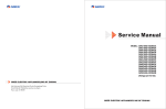
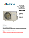
2.2 Operation Characteristic Curve
18K
<Cooling>
<Heating>
11
Current (A)
8
9
8
7
6
230V
5
4
3
7
230V
6
5
240V
4
3
240V
2
220V
10
Current (A)
9
11
220V
• Conditions
Indoor : DB27˚C/WB19˚C
Outdoor : DB35˚C/WB24˚C
Indoor air flow : High
Pipe length : 5m
10
• Conditions
Indoor : DB20˚C/WB15˚C
Outdoor : DB7˚C/WB6˚C
Indoor air flow : High
Pipe length : 5m
2
1
1
0
0
0
10
20
30
40
50
60
80
70
90
0
10 20 30 40 50 60 70 80 90 100 110 120
Compressor speed (rps)
Compressor speed (rps)
24K
<Cooling>
<Heating>
11
11
• Conditions
Indoor : DB27˚C/WB19˚C
Outdoor : DB35˚C/WB24˚C
Indoor air flow : High
Pipe length : 5m
9
Current (A)
8
220V
10
220V
9
8
Current (A)
10
7
6
230V
5
4
7
230V
6
5
240V
4
3
3
240V
2
• Conditions
Indoor : DB20˚C/WB15˚C
Outdoor : DB7˚C/WB6˚C
Indoor air flow : High
Pipe length : 5m
2
1
1
0
0
0
10
20
30
40
50
60
70
80
90
0
10 20 30 40 50 60 70 80 90 100 110 120
Compressor speed (rps)
Compressor speed (rps)
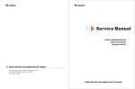
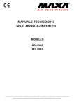
2.3 Capacity Variation Ratio According to Temperature
<Cooling>
<Heating>
105
110
100
100
Capacity ratio (%)
Capacity ratio (%)
95
90
85
80
75
70
• Conditions
Indoor : DB27˚C/WB19˚C
Indoor air flow : High
Pipe length : 5m
65
60
55
50
32
33
34
35
36
37
38
39
40
Outdoor temp. (˚C)
41
42
90
80
70
60
• Conditions
Indoor : DB20˚C/WB15˚C
Indoor air flow : High
Pipe length : 5m
50
43
40
–15
–10
–5
0
5
7
10
Outdoor temp. (˚C)
11
Specifications
2.4 Operation Date
(1)Models: EVI18 EVI18 5A, EVO18 EVO18
EVI24 EVI24 EVO24 EVO24
Cooling
Temperature condition
(°C)
Indoor
27/19
Outdoor
35/24
Model
name
Standard
pressure
P (MPa)
Heat exchanger pipe
temp.
T1 (°C)
T2 (°C)
Compresso
Indoor fan Outdoor fan r revolution
mode
(rps)
mode
18K
0.9 to 1.1
12 to 14
70 to 40
Super High
High
67
24K
0.8 to 1.0
10 to 12
72 to 40
Super High
High
80
Model
name
Standard
pressure
P (MPa)
Heat exchanger pipe
temp.
T1 (°C)
T2 (°C)
18K
2.2 to 2.4
70 to 35
2 to 4
Super High
High
62
24K
2.5 to 2.7
70 to 35
0 to 3
Super High
High
78
Heating
Temperature condition
(°C)
Indoor
20/–
Outdoor
7/6
(2)Models: EVO18 EVO18 EVO18 EVO24
Compresso
Indoor fan Outdoor fan r revolution
mode
mode
(rps)
EVO24 EVO24
Cooling
Temperature condition
(°C)
Indoor
27/19
Outdoor
35/-
Model
name
Standard
pressure
P (MPa)
Heat exchanger pipe
temp.
T1 (°C)
T2 (°C)
Compresso
Indoor fan Outdoor fan r revolution
mode
(rps)
mode
18K
0.9 to 1.1
12 to 14
70 to 40
Super High
High
72
24K
0.8 to 1.0
10 to 12
72 to 40
Super High
High
83
Model
name
Standard
pressure
P (MPa)
Heat exchanger pipe
temp.
T1 (°C)
T2 (°C)
18K
2.2 to 2.4
70 to 35
2 to 4
Super High
High
66
24K
2.5 to 2.7
70 to 35
0 to 3
Super High
High
75
Heating
Temperature condition
(°C)
Indoor
20/–
Outdoor
7/6
Compresso
Indoor fan Outdoor fan r revolution
mode
(rps)
mode
NOTES :
(1) Measure surface temperature of heat exchanger pipe around center of heat exchanger path U
bent. (Thermistor themometer)
(2) Connecting piping condition : 5 m
(3) P: pressure of air pipe connected to the indoor and outdoor units (gas valve side)
T1: Inlet and outlet temperature for evaporator
T2: Inlet and outlet temperature for condenser
12
Specifications
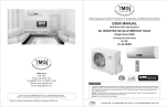
2.5 Noise criteria curve tables for both models
Indoor side noise when blowing
54
Heating
50
52
24K
40
Noise dB(A)
Noise/dB(A)
50
18K
48
Cooling
46
44
42
30
Low
Middle
High
40
Indoor fan motor rotating speed
20
30
40
50
60
70
80
90
Compressor frequency(Hz)
13
Constrction views
3. Construction Views
3.1 Indoor Unit
H
ON/OFF
W
D
Over 15mm
Over
Over
15mm
15mm
18K Wall Mounting Frame
24K Wall Mounting Frame
865
540
175
1008
685
130
150
193
319
298
φ55
φ55
φ55
φ55
40
40
50
50
100
124
Model
18K
24K
14
W()
865
1008
H()
305
319
D()
215
221
Constrction views
3.2 Outdoor Unit
891
700
341
955
396
Over 50cm
364
560
O
v
3
er
0c
m
Over 30cm
Over 50cm
00cm
Over 2
Bolt
Nut
Wrench
15
Refrigerant System Diagram
4. Refrigerant System Diagram
4.1 18K
(1)Cooling Only Models
INDOOR UNIT
OUTDOOR UNIT
GAS SIDE
3-WAY VALVE
Muffler
Discharge
HEAT
EXCHANGE
(EVAPORATOR)
Suction
Accumlator
COMPRESSOR
HEAT
EXCHANGE
(CONDENSER)
LIQUID SIDE
2-WAY VALVE
Strainer
Capillary
Strainer
COOLING
(2)Cooling & Heating Models
INDOOR UNIT
OUTDOOR UNIT
GAS SIDE
3-WAY VALVE
4-Way valve
Muffler
Discharge
HEAT
EXCHANGE
(EVAPORATOR)
Suction
Accumlator
COMPRESSOR
HEAT
EXCHANGE
(CONDENSER)
LIQUID SIDE
2-WAY VALVE
Strainer
Capillary
Strainer
COOLING
HEATING
Refrigerant pipe diameter
Liquid : 1/4" (6 mm)
Gas : 1/2" (12 mm)
16
Refrigerant System Diagram
4.2 24K
(1)Cooling Only Models
INDOOR UNIT
OUTDOOR UNIT
GAS SIDE
3-WAY VALVE
Muffler
Discharge
HEAT
EXCHANGE
(EVAPORATOR)
Suction
Accumlator
COMPRESSOR
HEAT
EXCHANGE
(CONDENSER)
LIQUID SIDE
2-WAY VALVE
Strainer
Expansion valve
Strainer
COOLING
(2)Cooling & Heating Models
INDOOR UNIT
OUTDOOR UNIT
GAS SIDE
3-WAY VALVE
4-Way valve
Muffler
Discharge
HEAT
EXCHANGE
(EVAPORATOR)
Suction
Accumlator
COMPRESSOR
HEAT
EXCHANGE
(CONDENSER)
LIQUID SIDE
2-WAY VALVE
Strainer
Expansion valve
Strainer
COOLING
HEATING
Refrigerant pipe diameter
Liquid : 1/4" (6 mm)
Gas : 1/2" (12 mm)
17
Schematic Diagram
5. Schematic Diagram
5.1 Electrical Date
Indoor Unit
=
J`
k
\|
k[
?
Jj`
kjj]
\|
kjj]\[
=
J[
Jj
J}
?
J\][
Jj`
Jj ?}
\$?$'{ \$^
Outdoor Unit
=
?@
?%
= $
?~
?JJZ@
?JJZ_
{\j |
?~\==\
\$?$'{ \$^
=
J[
J`
J}
]^
?
J\][
Jj`
Jj ?}
\ [
]^'$
=
]^
k
\|
k[
?
]^'$
kjj]
\|
kjj]\[
5.2 Electrical wiring
Indoor Unit
TUBE
TEM. SENSOR
RECEIVER AND
DISPLAY BOARD
AP2
ROOM
TEM. SENSOR
BU
BN
YEGN
0
RT1
0
RT2
AC-L
PGF
N
COM-OUT
AP1
JUMP
DISP2
PG
L-OUT
NO COM
1BU
2BK
3BN
L
L
TERMINAL
BLOCK
N(1) BU
BK
2
BN
3
YEGN
XT
4YEGN
PE
M2
SWING
MOTOR
18
EARTH-PLATE
M1
FAN
MOTOR
PE
EVAPORATOR
OUTDOOR UNIT
CAP
SWING-UD
DISP1
ROOM
TUBE
N
L
Schematic Diagram
Outdoor Unit
Model: EVI18 EVO24
4WH
WARNING
OUTROOM
TEM.SENSOR
OUTTUBE
TEM.SENSOR
RT2
0
INDOOR UNIT
XT
PE
YE
PE
BU
RD
COMP-V
COMP-U
COMP-W
OVC-COMP
N
BK
BN
2
3
3RD
X1
T-SENSOR
BU
C(T,U)
2BU
1YE
RT3
0
BK
PE
N(1)
S(W,X)
EXHAUST
TEM.SENSOR
WH
BU
BK
BN
COMPRESSOR
COMP E 6YEGN
R(M,V)
RT1
0
YEGN
SAT
5WH
Please don't touch any terminal when the
voltage of terminal P(DC+) and N(DC-) at
AP1 is higher than 30V to prevent the risk
of electrical shock!
AP1
COM-INNER(1)
AC-L
TERMINAL BLOCK
YEGN
OFAN
FA
INDC1
PE
RD
YE
M YEGN
~
C1
BN
PFCC2
YE
OG
WH
EKV
PFCC1
INDC2
C2
PE
L
FAN MOTOR
Models: EVO18 EVO18 EVO24 EVO24
4WH
WARNING
OUTROOM
TEM.SENSOR
OUTTUBE
TEM.SENSOR
RT2
0
INDOOR UNIT
XT
2
3
BU
BK
BN
TERMINAL BLOCK
YEGN
C(T,U)
2BU
1YE
RT3
0
3RD
PE
X1
BK
YE
PE
COMP-U
PE
N(1)
S(W,X)
EXHAUST
TEM.SENSOR
WH
BU
BK
BN
COMPRESSOR
COMP E 6YEGN
R(M,V)
RT1
0
YEGN
SAT
5WH
Please don't touch any terminal when the
voltage of terminal P(DC+) and N(DC-) at
AP1 is higher than 30V to prevent the risk
of electrical shock!
T-SENSOR
BU
RD
COMP-V
COMP-W
OVC-COMP
N
AP1
COM-INNER(1)
AC-L
OFAN
FA
4V
INDC1
PE
INDC2
OG
WH
4YV
4-WAY
VALVE
RD
EKV
C1
BN
M YEGN
~
FAN MOTOR
PE
PFCC1
PFCC2
YE
YE
C2
L
19
jk+
;
<=++
qz{:
neutral line connects
the terminal of
copper pin
fan capacitor
PG motor terminal
auxiliary relay K1, K2
up&down swing
terminal
health relay K3
protective
tube
piezoresistor
jumper cap
PG feedback
terminal
ambient temperature sensor
terminal
tube temperature
sensor terminal
supply power for
outdoor unit's
control relay K4
connect to the copper
pin of communication
line of outdoor unit
rectifier DB1
high-frequency
transformer T1
connect the terminal of diaplay
board DISP1, DISP2
filter SF2022A-05220
20
Schematic Diagram
BOTTOM VIEW
21
U20
BD1
(YE)
PZ1
RV4
C13
COMP-U
(YE)
COMP-V
(BU)
C301
14 +
13
PFCC2
(YE)
PFCC1
(OG)
INDC2
C120
D11
D12
CN101
C302
C69
C70
C71
D13
C74
COMP-W
(RD)
C60
1
R131
+
C118
U14
C303
D101
C72
U13
D42
C218
C164
U6
U21
2010.01.06
+
C217
C224
GRJW823-A V1.3
C304
+
R100
U2
BD
D44
C66
D18
3
J1
T1
C54
L4
C65
2 3
C62
+C305
D41
D19
C223
C225
Y1
C73
C2
C63
C222
PTC1
L2
INDC1
3
D2
<WH>
4
FA
CN5
D21
C219
C221
C216
C227
C64
OVC-COMP T-SENSOR
D27
HPP
D24
SOLD
D25
1 2 3 4 5 6 7 8 9
13 14
BD2
Q16
0
R127
U22
U7
HI
R128
U23
IPM1
SMT AI
6
N
C
D26
C103
12
CN9
Q3
5
HALL
C3
C4
CT1
K1
K2
U19
C25
FU1
R69
D3
R2
U12
U15
K4
CN102
U5
R68
FU2
C24
K6
R15
K5
T3.15AL 250V
ZD4
ZD3
D2
7
4V
L1
RV1
RV3
C5
C6
8
10
(YEGN)
PE
TVS1
AC_L
9
(BK)
(BN)
N
C1
RC2
COM-INNER
R185
D1
J103
J102
RC1
HEAT
11
(BU)
RV2
50/18K/24K T25AH 250V
72 : T30AH 250V
ZD1
ZD2
R67 R70
K3
6
OFAN
4
R18
22
1 2
R14
TOP VIEW
Schematic Diagram
D20
4
Schematic Diagram
R151
C7
R152
C220
C32
R201
R202
R200
C115
R162
R164
R161
R26
Q17 R181 R142
R9
R87
R206
R205
R165
R192
C92
C88
C89
C91
D28
C93
R86R84
R82
R113
R170
C94
C100 C102
C8 6
C80
C87
C79
C6 7
D10
C85
R199
D46
R138
D45
C101
C145
C9 5
R150
R31
C90
C96
Q11
Q23
C10
R85
R207
R7
C130R8 R5
R83
C12
R10
RS8
10
R153
R126
Q18
R197
R60
RS3
D47
R198
RS4
3
RS6
RS5
R2 37
R240
R243
D37
RS1
C14
R189
R43
C21 R88
R143
C128 C127 C99
R72
R129
D39
C59
D43 U24
2
D9 C31
R125
C35
R74
C42
R121
R21
D17
R94
R96
R93
R95
R92
R97
(E)
8
7
(AC-L)
(N)
U
BOTTOM VIEW
V
W
R120
Q9
Q5
C40
R36
D22
C29
C30
D14
C370
D31
C39
D32
R118
R76
R75
R79
Q1
C2 3
1
R1 8
C37
D290
R114 R123
C159
U9
R167
R11
Q6
U8
R140
D29
R148
HU
R3
C9
C8
R4
C36
R78
R73
D4
R71
R141
R168
R1 66
C81
U10
R144
R160
HW
C34
R91
C44 C41
R62
R171
R1 47
R116
D40
POWER
D7 D8
R174
R65
R64
C50
R149
+5V
R155
C121
U3
R89
R20 R29
R172
C51 C57 C53
C46 R63
R17
R146
R145 R179
R178
C52
C47 R6
C4 8
R175
R159
R90
C49
R173
R169
C82
R1 39
C56
U4
C19
C28
C45
R66
R81
R154
R1 30
R134
C78
R77
C38
C55
R50 R124
C11 7
C77 R51
C83
C84
6
C75
C124
R133
R193
R122
C108
C33
C111
SGND
C58
R19
R115
R196
R33
R32
R23
R35
C18
C98
1
R59
C20
R27
R16
R132
C97
C109
R180
R34
C135
R54
C26
D34
HV
D15
R49
R98
9
U1
C116
C43 C76
R30
C122 C123
R109
R1
C113 C1 14
C147
R163
R13
R105 R106
C125
C107 C119
R111
C22
C27
R101
D33
D35
R58
R37
C17
C15
R186
R107
R5 7
R28
R53
R52
4 3 2 1
R56
R61
R176
C112
R177
D30 D16 D6 D5
R55
C144
R25 C136
R117
C16
C110
C11
YE
COMP-U
(BU)
COMP-V
R80
C105
(RD)
C1 06
R38
COMP-W
R41
R40
C146
C131
U11
R39 C104
R110
C141 C142 C143 C137 C139 C140
R136 R135 R99 R187 R157 R137
R102
R108
C126
C163
C134
R42
R24 C68
R44
C132
R45
R104
C133
R48
R112
R22
R103
R158 R156
5
R249
C162
R46
R47
R119
R183
R182
C138R12
D36
R188
R233
R236
R239
R242
R245
R248
R246
D38
DC+
R234
R2 32
R235
R238
R241
R244
R247
RS2
23
Schematic Diagram
TOP VIEW
No.
1
2
Interface name
Interface of compressor
Overload protector
compressor
of
3
Temperature sensor
4
Electron expansion valve
5
Fan HALL interface
6
7
8
9
10
11
12
13
14
Outdoor fan
Four-way valve
Communication interface
for indoor unit
Live wire
Earthing wire
Neutral wire
Interface 1of reactor
PFC capacitor interface
Interface 2 of reactor
BOTTOM VIEW
No.
@
%
_
Z
@&
24
Circuit module
~'
J
??
?
~?`
?"{
?
'`
=~=
'~
Instruction
The corresponding three wires are: yellow-COMP-U,
blue-COMP-V, red-COMP-W
The corresponding two-core white wire connects the
overload protector SAT
Tube temperature (20k@25oC); outdoor
ambient temperature(15k@25oC), discharge
temperature(50 k@25oC)
It’s used for connecting the 5-core electron expansion
valve EKV
It’s used for connecting DC fan’s HALL sensor (there’s no
interface for AC motor)
It’s used for connecting the FAN-MOTOR
It’s used for connecting four-way-valve YV
Communication wire of indoor and outdoor units, which is
connected to the indoor unit
Power-Source “L” line
Connect to Earth
Power-Source “N’line
Connect to one terminal of inductor (Whilt)
Connect to C2(Refer to electric circuit diagram)
Connect to one terminal of inductor (orange)
Function and Control
6. Function and Control
6.1 Remote Controller Description
1
ON/OFF
Press this button to start or stop operation.
2
FAN
AUTO
MODE
Press it to select operation mode
OPER
(AUTO/COOL/DRY/FAN/HEAT).
AIR HEALTH X-FAN
HUMIDITY
3
FILTER
-:
Press it to decrease temperature setting.
TURBO
HOUR
4
ON/OFF
+:
Press it to increase temperature setting.
5
2
1
ON/OFF
FAN
Press it to set fan speed.
MODE
6
3
4
Press it to set up &down swing angle.
6
5
7
FAN
HEALTH SAVE(page 16)
Press it to select health mode on or off.
8
7
8
9
10
X-FAN
12 TURBO13
TEMP
TIMER
SLEEP
LIGHT
Press it to set left & right swing angle.
11
14
9
X-FAN (page 17)
10
TEMP (page 17)
11
TIMER
Press it set auto-on timer/auto-off timer.
12
TURBO (page 17)
13
SLEEP (page 17)
14
LIGHT
※ “X-FAN” first “BLOW”,Function homology.
25
Function and Control
1
ON/OFF :
Press this button to start the unit operation .Press this button again to stop the unit operation.
MODE :
2
Each time you press this button,a mode is selected in a sequence that goes from AUTO, COOL, DRY, FAN,and
HEAT *, as the following:
AUTO
COOL
DRY
FAN
HAET *
*Note:Only for models with heating function.
After energization, AUTO mode is defaulted. In AUTO mode, the set temperature will not be displayed on the
LCD, and the unit will automatically select the suitable operation mode in accordance with the room temperature
to make indoor room comfortable.
3
Press this button to decrease set temperature. Holding it down above 2 seconds rapidly decreases set temperature.
In AUTO mode, set temperature is not adjustable.
4
Press this button to increase set temperature.Holding
it down above 2 seconds rapidly increases set temperature.
.
In AUTO mode, set temperature is not adjustable.
5
FAN
This button is used for setting fan speed in the sequence that goes from AUTO,
Auto.
,
, to
, then back to
Auto
Low speed
Medium speed
High speed
:
6
● Press
button to start or stop up & down swing function.The remote controller defaults to simple swing condition.
Press + button and
● blinking 2 seconds.
button at the same time at unit OFF to switch between simple swing and static swing,
In static swing condition, press
button, the swing angle of up & down louver changes as below:
●
OFF
● If the unit is turned off during swing operation,the louver will stop at present position.
7
HEALTH SAVE:
Press HEALTH part of this button to turn on or off HEALTH function.
Pressing SAVE part of this button,
is displayed and the unit goes into SAVE operation mode. Press SAVE
part of the button again to cancel SAVE function .During SAVE operation, the tmperature and fan speed is not
adjustable.
8
:
● Press
condition.
26
button to start or stop left & right swing function.The remote controller defaults to simple swing
Function and Control
● Press + button and
button at the same time at unit OFF to switch between simple swing and static swing,
blinking 2 seconds.
● In static swing condition, press
button, the swing angle of left & right louver changes as below:
● If the unit is turned off during swing operation,the louver will stop at present position.
9 X-FAN:
Pressing X -FAN button in COOL or DRY mode,the icon "X-FAN" is displayed and the indoor fan will continue
operation for 10 minutes in order to dry the indoor unit even though you have turned off the unit.
After energization, X-FAN OFF is defaulted. X-FAN is not available in AUTO,FAN or HEAT mode.
10 TEMP:
Pressing TEMP button,
(set temperature),
(indoor ambient temperature) and
(outdoor
ambient temperatur) is displayed circularly .The unit defaults not to display the icon. During operation of TEMP
button, the set temperature is always displayed.
Note: Outdoor ambient temperature is only displayed for some models.
11 TIMER:
Press TIMER button at unit ON to set TIMER OFF, HOUR OFF blinking. Press TIMER button at unit OFF to set TIMER
ON, HOUR ON blinking. In this case, pressing + or - button changes time setting.
Holding down either button rapidly changes time setting (time setting range 0.5-24hours). Press TIMER button again to
confirm setting, HOUR ON/OFF stopping blink. If there is not any operation of button within 5 seconds during HOUR
ON/OFF blinking, TIMER setting will be canceled.
12 TURBO:
Press this button to activate / deactivate the Turbo function which enables the unit to reach the preset
temperature in shortest time. In COOL mode, the unit will blow strong cooling air at super high fan speed.
In HEAT mode, the unit will blow strong heating air at super high fan speed. (This function is not applicable for
some models).
13 SLEEP :
Press this button to go into the SLEEP operation mode. Press it again to cancel. This function is available in COOL ,
HEAT (Only for models with heating function) or DRY mode to maintain the most comfortable temperature for you.
14 LIGHT:
Press LIGHT button to turn on the display's light and press this button again to turn off the display's light. If the light
is tunrned on ,
is displayed. If the light is tunrned off
disappears.
4 and 3
About lock:
Press "+ " and "-" buttons simultaneously to lock or unlock the keypad. If the remote controller is locked,
displayed. In this case, pressing any button,
blinks three times.
3 and 2
is
About switch between fahrenheit and cenrigrade
At unit OFF, press "MODE" and "- " buttons simultaneously to switch between ℃ and ℉.
27
Function and Control
6.2 Changing batteries and notices
Remove the battery cover plate from the rear of the remote controller.(As shown in the figure)
1. 2 Take out the old batteries.
3. Insert two new AAA1.5V dry batteries, and pay attention to the polarity.
4 Replace the battery cover plate.
ƾ NOTE:
ƽ When replacing the batteries, do not use old or different batteries,
otherwise, it may cause malfunction.
ƽ If the wireless remote controller will not be used for a long time, please
remove batteries to prevent damage from leaking batteries.
ƽ The operation should be performed in its receiving range.
ƽ It should be kept 1m away from the TV set or stereo sound sets.
ƽ If the wireless remote controller does not operate normally, please take
the batteries out and replace them after 30 seconds. If still not operating
properly, replace the batteries.
Sketch map for
changing batteries
6.3 Unit indlcation section
1.When the unit is energized, all the display marks will be shown and only
the power LED lights.
2.When the unit is turned on remotely, the power LED goes out while the
current setting running mode is displayed.
3.During defrosting, “H1” is displayed in “dual 8”.
COOL light (blue)
DRY light (green)
4.In normal situation, the setting temperature is displayed in “dual 8” place.
5.When the signal of displaying indoor temperature or outdoor temperature is received from the controller, the corresponding temperature will be
shown in “dual 8” place. It resumes displaying setting temperature 5s
later.
RUN light (red)
HEAT light (orange)
ON/OFF
Unit ON/OFF button
6.4 Unit ON/OFF button
If the wireless remote control is lost or broken, please use the manual switch button. At this time, the unit will run at the
Auto mode, but the temperature and fan speed cannot be changed. The operation was shown as below:
To open the panel, the manual switch is on the displayer box.
Turn on the unit: At unit turned off, press the button,the unit will run at Auto mode immediately.The microcomputer will accord to
the indoor temperature to select (Cooling, Heating, Fan) and obtain the comfortable effect.
Turn off the unit: At unit turned on, press the button, the unit will stop working.
Operation of automatic buttons:
less than 5s
28
operation
during stop
start running
operation
during running
stop running
operation during stop
˄communication error˅
(after running, abnormal)
keep 5 ~ 10 s
start compulsory running
stop running
keep more than 10s
stop compulsory running
(avoid button lock)
Function and Control
6.5 Description of Each Control Operation
Indoor Unit
Temperature Parameter
ƹ Room setting temperature (Tpreset)
ƹ Room ambient temperature (Tamb.) (temperature sensor :15K, partial pressure resistance:15K)
ƹ Surface temperature of copper pipe for indoor heat exchanger (Tindoor tube) (temperature sensor: 20K, partial pressure resistance: 20K)
1. Basic Functions of System
(1) Cooling Mode
1. In this mode, indoor fan and swing will operate according to the setting status. The temperature setting range is 16~30ć.(Fahrenheit: 61~86̧).
2. When the unit stop operation due to malfunction of outdoor unit or protection, indoor unit will keep original operating status. Malfunction code will be
displayed.
3. When 0(Tpreset-Tamb.), if the indoor unit is operating at high fan speed, the speed of fan will change to medium fan speed; if the indoor unit is
operating at medium or low fan speed, the speed of fan will keep the same; (This condition can only be carried out after the compressor is started up);
There’s no change for super-high fan speed; when (Tamb.-Tpreset)1ć, the fan speed will resume setting fan speed;
(2) Dry Mode
1. In this mode, fan will operate at low fan speed and swing will operate at setting status. The temperature setting range is 16~30ć.(Fahrenheit:
61~86̧).
2. When the unit stop operation due to malfunction of outdoor unit or protection, indoor unit will keep original operating status. Malfunction code will be
displayed.
(3) Fan Mode
1. In this mode, indoor fan will operate at high, medium, low or auto fan speed. Compressor, indoor fan and the four-way valve will all stop operation.
2. In this mode, the temperature setting range is 16~30ć.(Fahrenheit: 61~86̧).
(4) Heating Mode
1. In this mode, the temperature setting range is 16~30ć. (Fahrenheit: 61~86̧).
2. Working condition and process of heating: when the unit is turned on in heating mode, indoor unit enters into anti-cold air condition; when the unit is
tuned off, the unit will enter into the condition of blowing residual heat.
3. Protection function: in heating mode, when the compressor is stopped due to malfunction, indoor fan will operate at the condition of blowing residual
heat.
4. Defrosting control: after receiving the defrosting signal from outdoor unit, the defrosting code H1 will be displayed.
5. Anti-cold function
6. Blowing residual heat function;
a. During heating operation, when the stopping condition for the compressor is reached, the compressor and the outdoor fan motor stop operation. The
upper& down horizontal louver will rotate to the horizontal position L. The indoor fan will be stopped after operating for 60s at setting speed.
b. Due to the blockage of PG motor, horizontal louver will keep the stop position when the unit is turned off. (In other modes) When the unit is stopped
due to other malfunctions, up&down horizontal louver will rotate to horizontal position L. The indoor fan will be stopped after operating for 60s at setting
speed.
c. If the unit is turned off when the compressor is operating in heating mode or auto heating mode, up&down horizontal louver will rotate to horizontal
position L. The indoor fan will be stopped after operating for 60s at setting speed.
(5) Auto Mode
1. When Tamb.26ć, the unit will operate in cooling mode. The implied setting temperature is 25ć. ((Fahrenheit: 77̧).
2. Heat pump type: when Tamb22ć, the unit will operate in heating mode. The implied setting temperature is 20ć. ((Fahrenheit: 68̧).
3. Cooling only unit: when Tamb25ć, the unit will operate in auto mode. The implied setting temperature is 25ć. ((Fahrenheit: 77̧).
4. When 23ćTindoor amb. 25ć, the unit will operate in auto fan mode if the unit is turned on and enters into the auto mode for the fist time. If the
unit is switched to auto mode from other mode, it will keep the previous operation mode (if the unit is switched to auto mode from dry mode, the unit will
operate at auto fan mode).
2. Display Status of Indoor Indicator
(1) Status of Indoor Display Board
1. After energization, all the icons will be displayed and then only the power indicator is bright. When the unit is turned on by remote controller, the
operation indicator will be bright. Meanwhile, the current setting operation mode will be displayed.
2. During defrosting, “dual-8” will display “H”.
3. “Dual-8” displays setting temperature.
¾
Display of Operation Icon and Mode Icon
After energization, all the icons will be displayed for once. In standby status, the operation indicator will be in red. If turn on the unit by remote controller,
the operating indication icon will be bright. Meanwhile, the current setting operation mode will be displayed (mode indicator: cooling indicator, heating
indicator, dry indicator). If turn off the light button, all displays will be turned off.
¾
Temperature display control mode for split type unit
1. When user set the remote controller as the setting temperature display status, the current setting temperature will be displayed on remote
controller.
2. Only when the remote control signal is switched to indoor ambient temperature display status from other display status, controller will display the
indoor ambient temperature for 5s and then turn back to display the setting temperature.
3. When user hasn’t set the temperature displaying status, it will be displayed according to the setting temperature.
(2)Malfunction Display of Indoor Unit
29
Function and Control
When multiple malfunctions occurred simultaneously, malfunction protection codes will be displayed in cycle.
3.Other Control Target
(1) Up&down swing function: the mode for swing motor is MP28EA
After energization, up & down swing motor will firstly let the horizontal louver anticlockwise rotate to
position 0 to close air outlet.
If swing function has not been set after startup of the unit, up & down horizontal louver will clockwise turn
to position D in HEAT mode, or clockwise turn to level position L in other modes.
If setting swing function while starting up the unit, the horizontal louver will swing between L and D.
There are 7 kinds of swing status of horizontal louver: Positions L, A, B, C and D, swing between L
and D and stop at any position between L and D.
Upon turning off the unit, the horizontal louver will close at position 0. Swing function is available
only when swing function set and indoor fan is operating.
Note: If the position is set between L and B, A and C or B and D by remote controller, the horizontal louver will swing between L and D.
L----A----B----C----D
(2) Buzzer
Upon energization and operation, the buzzer will give out sound.
(3) Auto Button
After pressing this button, the unit will operate in auto mode. Indoor fan will operate at auto fan speed and swing motor will operate. Press
this button again to turn off the unit. The complete unit is energized when pressing the button and the complete unit will enter into fast
testing status. After energization, if it’s detected that the auto button is pressed down and the complete unit is at fast testing status, the fast
testing status will be exited.
(4) Sleep Function
This mode is only valid in cooling and heating mode. The unit will select the appropriate sleeping curve to operate according to the
different setting temperature.
During cooling mode:
(1) When the initial temperature is set as 16~23ć, after starting up the sleep function, the temperature will increase by1ć every one hour.
After the temperature has increased by 3ć, the unit will keep this temperature. When the unit has operated for 7 hours, the temperature
will decrease by 1ć and then the unit will operate at this temperature all the time;
(2) When the initial temperature is set as 24~27ć, after starting up the sleep function, the temperature will increase by1ć every one hour.
After the temperature has increased by 2ć, the unit will keep this temperature. When the unit has operated for 7 hours, the temperature
will decrease by 1ć and then the unit will operate at this temperature all the time;
(3) When the initial temperature is set as 28~29ć, after starting up the sleep function, the temperature will increase by1ć every one hour.
After the temperature has increased by 1ć, the unit will keep this temperature. When the unit has operated for 7 hours, the temperature
will decrease by 1ć and then the unit will operate at this temperature all the time;
(4) When the initial temperature is set as 30ć, the unit will operate at this temperature. After the unit has operate for 7hours, the
temperature will decrease by 1ć and then the unit will operate at this temperature all the time.
During Heating Mode:
(1) When the initial temperature is set at 16ć, the unit will operate at this temperature all the time;
(2)When the initial temperature is set as 17~20ć, after starting up the sleep function, the temperature will decrease by1ć every one hour.
After the temperature is decreased by 1ć, the unit will operate at this temperature;
(3)When the initial temperature is set as 21~27ć, after starting up the sleep function, the temperature will decrease by1ć every one hour.
After the temperature is decreased by 2ć, the unit will operate at this temperature;
(3)When the initial temperature is set as 28~30ć, after starting up the sleep function, the temperature will decrease by1ć every one hour.
After the temperature is decreased by 3ć, the unit will operate at this temperature;
General timer and clock timer functions are compatible by equipping different functions of remote controller.
(5) Timer Function
General timer and clock timer functions are compatible by equipping different functions of remote controller.
General timer:
Timer ON
If timer ON is set during operation of the unit, the unit will continue to operate. If timer ON is set at unit OFF, upon ON time reaches the unit will start to
operate according to previous setting status.
Timer OFF
If timer OFF is set at unit OFF, the system will keep standby status. If timer OFF is set at unit ON, upon OFF time reaches the unit will stop operation.
(6) Blow Function
Blow function can be set in cooling and dry mode.
(7) Indoor Fan Control
Indoor fan can be set at super-high, high, medium or low. Meanwhile, the fan will operate at super-high, high, medium and low fan speed respectively
and it can also set at auto fan speed.
(8) Memory Function
Memory content includes mode, up & down swing, light, set temperature and set fan speed, general timer (clock timer can’t be memorized),
Upon power failure, the unit after power recovery will automatically start operation according to memorized content. The unit, without timer setting
before power failure, will operate according to the last setting after power recovery. The unit, with general timer setting which has not been fulfilled
30
Function and Control
before power failure, will memorize the time setting and re-calculate the time after power recovery. If there is timer function in the last remote controller
command but setting time has reached, the system will act as timer on/off setting before power failure. After power failure, the system memorizes the
operation states before power failure without timer action. Clock timer can not be memorized.
(9) Locked protection to PG motor
If the indoor fan motor’s rotational speed after startup keeps slow for a continuous period of time, the unit will stop operation and display “H6”.
(10)Turbo Function
This function can be set in cooling or heating mode to quickly cool or heat the room˄Turbo function is not available in auto, dry and fan mode˅. After
pressing the turbo button, indoor fan will operate at super-high fan speed.
5. Malfunction Detection for Temperature sensor
(1) Indoor ambient temperature sensor:
Malfunction of temperature sensor will be detected at any time;
(2) Indoor tube temperature sensor
Malfunction of temperature sensor won’t be detected during defrosting period. It starts detecting the malfunction of temperature sensor after defrosting
is finished for 5 mins. Malfunction of temperature sensor will be detected at any other time.
(3) Protection of temperature sensor
1. When the temperature sensor is detected short circuit for 30s successively:
The detected temperature by the temperature sensor is too high and the complete unit will stop operation, meanwhile, the protection and malfunction of
temperature sensor will be displayed accordingly.
2. When the temperature sensor is detected open circuit for 30s successively: The unit will stop operation due to protection and the corresponding
malfunction of temperature sensor will be displayed directly.
6. Compulsory operating function of indoor unit
(1) Enter into compulsory operation control
After the unit is energized for 5mins, press the light button on remote controller for 3 times in 3s successively to enter into Freon recovery mode. Fo will
be displayed. When Freon recovery mode operated for 25mins, all loads will operate in cooling mode. (The setting fan speed is high fan speed and the
setting temperature is 16ć)
(2) Exit the compulsory operation control
Freon recovery mode will be exited after receiving any signal from remote controller or button and then the unit will operate at the current setting
command; Freon mode will also be exited after operating for 25mins and then the unit will be turned off.
Outdoor Units
1. Input Parameter Compensation and Calibration
(1) Check the input parameter compensation function
As the instruction feature of split unit, concerning the comfortable, in heating mode, the indoor ambient temperature of compressor stopping time is higher
than preset temperature.
(2) Check effective judgment controls of parameters
Effective judgment function of the outdoor exhaust temperature thermo-bulb
When conditions a and b are satisfied, the outdoor exhaust temperature thermo-bulb is judged not to be connected into place, the mainboard of outer
units will display failure of the outdoor exhaust temperature thermo-bulb (not connected into place), stop the unit for repairing, and resume it by remote
controls of ON/OFF.
2. Basic Functions
(1) Cooling Mode
1. Conditions and processes of cooling operation:
(1) If the compressor is stop, and [Tpreset – (Tindoor ambient – Tcooling indoor ambient temperature compensation)] 0.5ć, start up the unit for
cooling, and start to cooling operation;
(2) During operations of cooling, if 0ć [Tpreset – (Tindoor ambient –Tcooling indoor ambient temperature compensation)] < 2ć, the cooling operation
will be still running;
(3) During operations of cooling, if 2ć [Tpreset – (Tindoor ambient –Tcooling indoor ambient temperature compensation)], the cooling operation will
stop after reaching to the temperature point.
2. Temperature setting range
(1) If Toutdoor ambient [Tlow-temperature cooling], the temperature can be set at: 16~30ć (Cooling at room temperature);
(2) If Toutdoor ambient < [Tlow-temperature cooling], the temperature can be set at: 25~30ć (Cooling at low temperature), that is, the minimum setting
temperature for outdoor unit judgment is 25ć.
(2) Dry Mode
1. Conditions and processes of dry operations: Same as the cooling mode;
2. The temperature setting range is: 16~30ć;
(3) Fan Mode
1. The compressor, outdoor fan and four-way valve are switched off;
2. The temperature setting range is: 16~30ć.
31
Function and Control
(4) Heating Mode
1. Conditions and processes of heating operations: (Tindoor ambient is the actual detection temperature of indoor environment thermo-bulb, Theating
indoor ambient temperature compensation is the indoor ambient temperature compensation during heating operations)
(1) If the compressor is stop, and [(Tindoor ambient –Theating indoor ambient temperature compensation) –Tpreset] 0.5ć, start the machine to enter
into heating operations for heating;
(2) During operations of heating, if 0ć [(Tindoor ambient –Theating indoor ambient temperature compensation) –Tpreset] < 2ć, the heating operation
will be still running;
(3) During operations of heating, if 2ć [(Tindoor ambient –Theating indoor ambient temperature compensation) –Tpreset], the heating operation will
stop after reaching the temperature point.
2. The temperature setting range in this mode is: 16~30ć.
(5) Defrosting Control
1. After the time for defrosting is judged to be satisfied, if the temperature for defrosting is satisfied after detections for continuous 3minutes, the defrosting
operation will start.
2. Start to defrost: Compressor stops and starts up 55S later;
3. Defrosting finish: Compressor stops and starts up 55S later;
4. Conditions of finishing defrosting
The defrosting operation can exit when any of the conditions below is satisfied:
(1) Toutdoor pipe 12ć;
(2) Toutdoor ambient⧞-5ć, and the Toutdoor pipe 6ć last more than 80S;
(3) The continuous running time of defrosting reaches to 8min.
(6) Compressor Control
1. The frequency of compressor will be controlled with the relationship of ambient temperature and preset temperature and changing speed of ambient
temperature;
2. Start the compressor after starting cooling, heating, dry operations, and the outdoor fan start for 5s;
3. When the unit is off, in safety stops and switching to fan mode, the compressor will stop immediately;
4. In all modes: once the compressor starts up, it will not be allowed to stop until having run for the [tmin. Compressor running time] (Note: including cases
of shutdown when the temperature point is reached; except the cases requiring stopping the compressor such as fault protection, remote shutdown, mode
switching etc.);
5. In all modes: once the compressor stops, it will be allowed be restart after 3-minute delay (Note: The indoor units have a function of power memory, the
machine can be restarted after remote shutdown and powering up again without delay).
(7) Outdoor Fan Control
1. When the unit is off by remote controlʙin safety stops and stop after reaching to the temperature point.
2. In fan mode: The outdoor fan stops;
3. Start to defrost: Outdoor fan will stop after compressor stops for 50S;
4. Defrosting finish: Outdoor fan will start up when the compressor is stopping.
(8) 4-way valve control
1. The 4-way valve control under the modes of Cooling, dehumidification and fan: closing;
2. When the unit is on in heating mode, the 4-way valve is energized;
3. When the unit is on in heating mode and heating mode shift to other modes, the 4-way valve will be de-energized after compressor stops for 2min;
4. After protection stops, the 4-way valve will be de-energized after 4min;
5. Start to defrost: The power of 4-way valve will be de-energized after the compressor stops;
6. Defrosting finish: The 4-way valve will be energized after the compressor stops.
(9) Anti-freezing protection
1. In cooling and dry mode, if Tindoor pipe˘0 is detected for 3min continuously, the unit will stop; if ˘Tindoor pipe, and compressor has stopped for
3min, the unit will resume running;
2. In cooling and dry mode, if Tindoor pipe˘6, running frequency of compressor will be decreased or stop to increase will be occurred;
3. If the unit stops as anti-freezing protection for 6 times, it can not resume running automatically and display malfunction, it can resume by pressing
ON/OFF. During operation, if the time exceeds compressor running time, the time of anti-freezing protection stop will zero clearing. When the unit is off/
fan/ heating mode, the malfunction and malfunction times will zero clearing. (If the malfunction can not resume, the shifting mode can clear malfunction.)
(10) Overload protection
1. In cooling and dry mode: if Toutdoor pipe, the unit will stop; if Toutdoor pipe˘, and compressor has stopped for 3min, the unit will resume running;
2. In cooling and dry mode: if Toutdoor pipe, running frequency of compressor will be decreased or stop to increase will be occurred;
3. In heating mode: if Tindoor pipe, the unit will stop; if Tindoor pipe˘, and compressor has stopped for 3min, the unit will resume running;
4. In cooling and dry mode: if Tindoor pipe, running frequency of compressor will be decreased or stop to increase will be occurred;
5. If the unit stops as overload protection for 6 times, it can not resume running automatically and display malfunction, it can resume by pressing ON/OFF.
During operation, if the time exceeds compressor running time, the time of overload protection stop will zero clearing. When the unit is off/ fan/ shifts to
32
Function and Control
heating mode, the malfunction and malfunction times will zero clearing. (If the malfunction can not resume, the shifting mode can clear malfunction.)
(11) Compressor discharge temperature protection
1. If Tdischarge, the unit will stop; if Tdischarge˘, and compressor has stopped for 3min, the unit will resume running;
2. If Tdischarge, running frequency of compressor will be decreased or stop to increase will be occurred;
3. If the unit stops as compressor discharge temperature for 6 times, it can not resume running automatically and display malfunction, it can resume by
pressing ON/OFF. During operation, if the time exceeds compressor running time, the time of compressor discharge temperature stop will zero clearing.
When the unit is off/ shifts to fan mode, the malfunction and malfunction times will zero clearing. (If the malfunction can not resume, the shifting mode can
clear malfunction.)
(12) Current protection
1. If 12AI alternating-current, running frequency of compressor will be decreased or stop to increase will be occurred;
2. If 17AI alternating-current, the unit will stop; and compressor has stopped for 3min, the unit will resume running;
3. If the unit stops as compressor discharge temperature for 6 times, it can not resume running automatically and display malfunction, it can resume by
pressing ON/OFF. During operation, if the time exceeds compressor running time, the time of compressor discharge temperature stop will zero clearing.
(13) Drop off voltage
During compressor operation, the system will stop and malfunction of drop off voltage if voltage downward fluctuates rapidly, and it will re-start up
automatically 3min later.
(14) Communication malfunction
If the unit does not receive correct signal from indoor unit for 3min continuously, the unit will stop as communication malfunction protection; if
communication malfunction resume and compressor has stopped for 3min, the unit will resume running.
(15) IPM module protection
When the compressor starts, if there is overcurrent or control voltage low for IPM module as some abnormal results, IPM will detect module protection
signal as the unit is on. Once the module protective signal is detected, stop the unit with module protection immediately. If the module protection is
resumed and compressor has stopped for 3min, the unit will be allowed to operate. If the module protection continuously occurs for three times, it should
not be resumed automatically, and you should press the ON/OFF button to resume. If the running time of compressor exceeds the [t Protection times
clearing of module], the module protection is cleared to recount.
(16) Module overheating protection
1. If Tmodule, running frequency of compressor will be decreased or stop to increase will be occurred;
2. If Tmodule, the unit will stop; if Tmodule˘, and compressor has stopped for 3min, the unit will resume running;
3. If the unit stops as module overheating protection for 6 times, it can not resume running automatically and display malfunction, it can resume by
pressing ON/OFF. During operation, if the time exceeds compressor running time, the time of module overheating protection stop will zero clearing. When
the unit is off/ shifts to fan mode, the malfunction and malfunction times will zero clearing. (If the malfunction can not resume, the shifting mode can clear
malfunction.)
(17) Compressor overload protection
1. If the switch of compressor overload de-energized is detected for 3S continuously, the system will stop as protection;
2. If the overload protection is resumed and compressor has stopped for 3min, the unit will be allowed to operate.
3. If the unit stops as compressor overload protection occurred for 3 times continuously, it can not resume running automatically and display malfunction,
it can resume by pressing ON/OFF; and the times of compressor overload protection will be cleared after the compressor has run for 30min.
33
Installation Manual
7. Installation Manual
Important Notices
1. The unit installation work must be done by qualified
personnel according to the local rules and this
manual.
2. Before installating, please contact with local
7.2 Installation Position Selection
(1)The air inlet and outlet vent should be far from the obstruction,
make sure that the air can be blown through the whole room.
(2)Select a position where the condensing water can be easily
drained out, and the place is easily connected for outdoor unit.
(3)Select a location where the children can not reach.
(4)Can select the place where is strong enough to withstand the
authorized maintenance center, if unit is not installed
full weight and vibration of the unit. And will not increase the noise.
(5)Be sure to leave enough space to allow access for routine
by the authorized maintenance center, the malfunction
may not solved, due to discommodious contacts.
maintenance. The height of the installed location should be
250cm or more from the floor.
3. When removing the unit to the o.ther place, please
firstly contact with the authorized Maintenance
Center in the local area.
(6)Select a place about 1m or more away from TVset or any other
electric appliances.
Basic Requirements For Installation
Position
(7)Select a place where the filter can be easily taken out.
(8)Make sure that the indoor unit installation should accord with
installation dimension diagram requirements.
(9)Do not use the unit in the immediate surroundings of a laundry a bath a shower or a swimming pool.
Install in the following place may cause malfunction. If it is
unavoidable contact with service center please:
(1)Select a location from which noise and outflow air emitted by
* Place where strong heat sources, vapors, flammable gas or
volatile object are emitted.
unit will not inconvenience neighbors, animals, plants.
(2)Select a location where there should be sufficient ventilation.
* Place where high-frequency waves are generated by radio
equipment, welders and medical equipment.
(3)Select a location where there should be no obstructions cover
the inlet and outlet vent.
* Place where a lot of salinities such as coast exists.
* Place where the oil (machine oil) is contained in the air.
(4)The location should be able to withstand the full weight and
vibration of the outdoor unit and permit safe installation.
* Place where a sulfured gas such as the hot spring zones is
generated.
(5)Select a dry place, but do not expose under the direct sunlight
or strong wind.
* Other place with special circumstance.
(6)Make sure that the outdoor unit installation dimension should
accord with installation dimension diagram, convenient for
7.1 Tools Required for Installation
(not supplied)
1. Gauge manifold
2.Electronic balance for refrigerant charging
3. Phillips head screwdriver
4. Knife or wire stripper
5. Carpenter’s level
9. Hammer
10. Drill
11. Tube cutter
12. Tube flaring tool
13. Torque wrench
14. Adjustable wrench
15. Reamer (for deburring)
16. Vacuum pump (For R410A)
17. Gas leakage detector
34
maintenance, repair.
(7)The height difference of connecting the tubing within 5m, the
length of connecting the tubing within 10m.
(8)Select a place where it is out of reach for the children.
(9)Select a place where will not block the passage and do not
influence the city appearance.
7.3 Installation of Indoor Unit
The mounting plate should be installed on a wall which can support the weight of the indoor unit.
1) Temporarily secure the mounting plate to the wall, make sure
that the panel is completely level, and mark the boring points on
the wall.
2) Secure the mounting plate to the wall with screws.
Installation Manual
Recommended mounting plate retention spots and
Burr removal
dimensions
1.Completely remove all burrs from the cut cross section of
18K:
Wall
Mark on the middle of it
pipe/tube.
2. Put the end of the copper tube/pipe in a downward direc-
Wall
Gradienter
Space
to the
wall
150mm
above
Space
to the
wall
150mm
above
tion as you remove burrs in order to avoid dropping burrs
into the tubing.
Pipe
Reamer
Left ¶PP
(Rear piping hole)
24K:
Right ¶PP
(Rear piping hole)
Mark on the middle of it
Wall
Gradienter
Point down
Wall
Space
to the
wall
150mm
above
Space
to the
wall
150mm
above
Left ¶PP
(Rear piping hole)
Right ¶PP
Putting nut on
Remove flare nuts attached to indoor and outdoor unit, then
put them on pipe/tube having completed burr removal.
(not possible to put them on after flaring work)
(Rear piping hole)
Flare nut
Copper tube
• For walls containing metal frame or metal board, be sure to use
a wall embedded pipe and wall cover in the feed-through hole to
prevent possible heat, electrical shock, or fire.
• Be sure to caulk the gaps around the pipes with caulking mate-
slope toward the outside.
2) Insert a wall pipe into the hole.
3) Insert a wall cover into wall pipe.
4) After completing refrigerant piping, wiring, and drain piping,
Flaring work
Firmly hold copper pipe in a die in the dimension shown in
the table above.
Handle
"A"
rial to prevent water leakage.
1) Bore a feed-through hole of 65mm in the wall so it has a down
Bar
Bar
Yoke
Cone
caulk pipe hole gap with putty.
Inside
Wall embedded pipe
(field supply)
Outside
Copper pipe
Clamp handle
Caulking
¶65
Wall hole cover
(field supply)
Wall embedded pipe
(field supply)
Red arrow mark
Carry out flaring work using flaring tool as shown below.
Outside diameter
mm
inch
A
mm
Ø6.35
1/4
0~0.5
3.1 Flaring work
Ø9.52
3/8
0~0.5
Flaring work
Ø12.7
1/2
0~0.5
Main cause for refrigerant leakage is due to defect in theflaring
work. Carry out correct flaring work using the follow-ing procedure.
Ø15.88
5/8
0~1.0
Ø19.05
3/4
1.0~1.3
Cut the pipes and the cable
1. Use the piping kit accessory or pipes purchased locally.
2. Measure the distance between the indoor and the outdoor unit.
3. Cut the pipes a little longer than the measured distance.
4. Cut the cable 1.5m longer than the pipe length.
Check
1.Compare the flared work with figure below.
2.If flare is noted to be defective, cut off the flared section and reflare it.
Smooth all round
Inside is shiny without scratches
Copper
pipe
90e
= Improper flaring =
Slanted Uneven Rough
Even length
all round
Inclined Surface Cracked Uneven
damaged
thickness
35
Installation Manual
3.2 Connection of piping
1.Align the center of the pipes and sufficiently tighten the flare nut
5. Insert the connecting cable fully into the terminal block and
secure it tightly with screws.
by hand.
6. Tightening torque: 1.2 N•m (0.12 kgf•m).
7. Secure the connecting cable with the cord clamp.
8. Attach the terminal cover, rear plate bushing and air inlet grille
on the indoor unit.
Indoor unit tubing
Flare nut
Pipes
CAUTION
2.Tighten the flare nut with a wrench.
• Be sure to refer to the wiring system diagram
Open-end wrench (fixed)
specific wiring instructions or limitations.
Flare nut
Wrench
labeled inside the front panel.
• Check local electrical regulations for any
Connection pipe
Indoor unit tubing
Terminal block
Outside diameter
mm
inch
Ø6.35
1/4
Ø9.52
3/8
Ø12.7
1/2
Ø15.88
5/8
Ø19.05
3/4
Torque
kg.m
1.8
4.2
5.5
6.6
6.6
Earth wire
Terminal cover
Screw
Screw
Cord clamp
Connecting cable
If drain hose extension or embedded drain piping is required,
use appropriate parts that match the hose front end.
Insert drain hose into the handle of drain pan, and join
drain hose and connecting hose according to the figure by.
Shield pipe
Terminal block
Drain hose Inside the room
Extension drain hose
CAUTION
CAUTION
Insert the drain hose and drain cap into the drain port, making sure that it comes in contact with the back of the drain
port, and then mount it. If the drain hose is not connected
properly, leaking will occur.
• Attach the Insulation (Drain hose) to the drain hose.
Insulation (Drain hose)
Connecting cable
About 15 cm
Drain hose
Wiring the connecting cable can be carried out without removing the front panel.
70 mm
10 mm
Earth line
1. Remove the air inlet grille. Open the air inlet grille upward and
pull it toward you.
2. Remove the terminal cover and cord clamp.
3. Insert the connecting cable (or as according to local regulations/codes) into the pipe hole on the wall.
4. Pull the connecting cable through the cable slot on the rear
panel so that it protrudes about 15 cm out of the front.
36
10 mm
50 mm
Installation Manual
How to replace the drain plug and drain hose
In the case of bending or curing refrigerant pipes, keep the following precautions in mind.
Abnormal sound may be generated if improper work is conducted.
1) Do not strongly press the refrigerant pipes onto the bottom
frame.
2) Do not strongly press the refrigerant pipes on the front grille,
either.
• How to remove the drain cap
Clamp drain cap with needle-nose pliers, and pull out.
• How to remove the drain hose
The drain hose is secured in place by a screw.
Remove the screw securing the drain hose, then
pull out the drain hose.
Insulation
fixing screw
Drain hose
• How to attach the drain cap
1. Insert hexagonal wrench (4 mm).
No gap
Do not apply lubricating oil
(refrigerant machine oil) when
inserting the drain cap. If applied,
deterioration and leakage of the
drain plug may occur.
2. Firmly insert drain cap.
• How to attach the drain hose
The piping can be lead out from right, right rear, left left rear.
Right-side, right-back, or right-bottom piping
1)After making slits on the front panel with a knife or similar tool,
cut them out with a pair of nippers or an equivalent tool.
Attach the drain hose to the underside of the refrigerant pipes
Insert a hexagon wrench
(4 mm)
Insert the drain hose firmly until the connector contacts the insulation, then
secure it in place using the original screw.
1.After making slits on the front panel with a knife or similar tool,
cut them out with a pair of nippers or an equivalent tool.
with an adhesive vinyl tape.
2) Wrap the refrigerant pipes and drain hose together with an
insulation tape.
Slit
2.Overlap the connection pipe insulation material and the indoor
Bind with vinyl tape
unit pipe insulation material. Bind them together with vinyl tape
so that there is no gap.
Plastic bands Insulation material
Right piping
Bottom
piping
Pipe (top)
Rear piping
Indoor unit drain hose
(bottom)
Left-side, left-back, or left-bottom piping
• Interchange the drain cap and the drain hose.
(1)
(2)
(3)
(4)
CAUTION
In order to align the drain hose and drain cap, be
sure to insert securely and vertically. Incline insertion will cause water leakage.
When inserting, be sure not to attach any material
besides water. If any other material is attached, it
will cause deterioration and water leakage.
After removing drain hose, be sure not to forget
mounting drain cap.
Be sure to fix the drain hose with tape to the bottom
of piping.
3.Wrap the area which accommodates the rear piping housing
section with vinyl tape.
Vinyl tape
(wide)
For left outlet piping, cut off the
piping outlet cutting groove
with a hacksaw.
Indoor unit
drain hose
Drain cap
Remove the drain cap by pulling
at the projection at the end of
the cap with pliers, etc.
Wrap with vinyl tape
Wrap with vinyl tape
Pipe
Vinyl tape(wide)
Drain hose
(5) Prevent drain water frozen under low temperature environment.
When installing indoor unit's drain hose outdoors, necessary
measure for frost protection should be taken to prevent drain
water frozen.
• Under low temperature environment (when outdoor temperature under 32 °F), after cooling operation is executed,
water in the drain hose could be frozen.
Once drain water is frozen, the drain hose will be blocked
and water leakage may be resulted for indoor unit.
Indoor
unit pipe
Connection
pipe
Indoor unit
Auxiliary pipes
Connecting
cable
Installation
plate
4.Bundle the piping and drain hose together by wrapping them
with vinyl tape for enough to cover where they fit into the rear
piping housing section.
Indoor unit installation
1) Pass the drain hose and refrigerant pipes through the wall
hole, then set the indoor unit on the mounting plate hooks by
using the markings at the top of the indoor unit as a guide.
37
Installation Manual
A Mounting plate
Drain-water hole
Bottom frame
Marking
Drain plug
Drain connecter
Hose (available commercially,
inner dia. 16mm)
2) Swing the indoor unit to right and left to confirm that it is firmly
hooked on the installation plate.
3)While pressing the indoor unit onto the wall, hook it at the lower
part on the installation plate.
Remove the Valve cover from the unit by loosening the screw.
Align the center of the pipings and sufficiently tighten the flare
nut by hand.
Pull the indoor unit toward you to confirm that it is firmly
hooked on the installation plate.
For detaching the indoor unit from the installation plate pull the
indoor unit toward you while pushing the bottom up at the
specified places.
Finally, tighten the flare nut with torque wrench until the wrench
clicks.
Outdoor unit
Push
Liquid side piping
(Smaller diameter)
Push
4)Run the drain hose at a downward sloped angle.
Do not rise the drain hose.
Do not form the drain hose
into the waved shape.
50 mm
or more
Torque wrench
Gas side piping
(Bigger diameter)
Do not put the
drain hose end
into water.
Do not put the drain
hose end in the
drainage ditch.
5)Put water in the drain pan and make sure that the water is
being drained outside.
Caution:
Install the drain pipe for proper drainage. Improper drainage can
result in water dripping inside the room.
7.4 Installation of Outdoor Unit
* Holes are provided on the base plate of the outdoor unit to
ensure that the defrost water produced during heating operations is drained off efficiently.
* If a centralized drain is required when installing the unit on a
balcony or wall.
* If the drain port is covered by a mounting base or floor surface,
place additional foot bases of at least 30mm in height under the
outdoor unit’s feet.
* In cold areas, do not use a drain hose with the outdoor unit.
(Otherwise, drain water may freeze, impairing heating
performance.)
38
2.Overlap the connection pipe insulation material and the indoor
unit pipe insulation material. Bind them together with vinyl tape
so that there is no gap.
After the piping has been connected to the indoor unit, perform
the air purge.
AIR PURGE
Evacuate the air in the connecting pipes and in the indoor
unit using a vacuum pump.
Do not use the refrigerant in the outdoor unit.
For details, see the vacuum pump manual.
Air purging with vacuum pump
Be sure to use a vacuum pump with counter-flow prevention
function so that oil inside the pump does not flow back into the
air conditioner pipes when the pump stops. (If oil inside the
vacuum pump enters into the air conditioner circuit which uses
R410A, trouble with the refrigeration system may develop.)
Installation Manual
1. Connect the charge hose from the manifold valve to the service
port of the gas side packed valve.
2. Connect the charge hose to the port of the vacuum pump.
1) Strip the insulation from the wire (20mm).
2) Connect the connection wires between the indoor and outdoor
3. Open fully the low pressure side handle of the gauge manifold
valve.
units so that the terminal numbers match. Tighten the terminal
screws securely.
4. Operate the vacuum pump to begin evacuating. Perform evacuating for about 15 minutes if the piping length is 20 meters (15
The screws are packed with the terminal board.
Terminal block
minutes for 20 meters) (assuming a pump capacity of 27 liters
per minute). Confirm that the compound pressure gauge reading is –101 kPa (–76 cmHg).
5. Close the low pressure valve handle of gauge manifold.
6. Open fully the valve stem of the packed valves (both sides of
Gas and Liquid).
7. Remove the charging hose from the service port.
8. Securely tighten the caps on the packed valves.
Compound
pressure
gauge
-101kPa
(-76cmHg)
Pressure gauge
Manifold valve
Handle Hi
(Keep full closed)
Handle Lo
Charge hose
(For R410A only)
Charge hose
(For R410A only)
Connecting
pipe
Vacuum pump
adapter for
counter-flow
prevention
(For R410A only)
Packed valve
at liquid side
Connecting cable
7.5 Test Operation
1. Check that all tubing and wiring have been properly connected.
2. Check that the gas and liquid side service valves are fully
open.
Check the flare nut connections for gas leaks with a gas leak
detector and/or soapy water.
Check places for
flare nut connections
(indoor unit)
Vacuum
pump
Packed valve at gas side
Service port
(Valve core (Setting pin))
Check places
for outdoor unit
CAUTION
• IMPORTANT POINTS FOR PIPING WORK
1. Keep dust and moisture from entering the pipes.
2. Tighten connections carefully (between pipes and unit).
3. Evacuate the air in the connecting pipes using a VACUUM
PUMP.
4. Check for gas leaks at all connections.
Packed Valve handling precautions
• Open the valve stem all the way; but do not try to open it beyond
the stopper.
• Securely tighten the valve stem cap with torque in the following
table:
Gas side (Ø9.52 mm)
33 to 42 N• m (3.3 to 4.2 kgf •m)
Liquid side (Ø6.35 mm)
14 to 18 N• m (1.4 to 1.8 kgf •m)
Service port
14 to 18 N• m (1.4 to 1.8 kgf • m)
1)Switch on power, press “ON/OFF” button on the wireless remote control to start the operation.
2)Press MODE button, to select the COOL, HEAT (Cooling only
unit is not available), FAN to check whether the operation is normal or not.
Perform test operation and check items 1 and 2 below.
1. INDOOR UNIT
(1) Is operation of each button on the remote control unit normal?
(2) Does each lamp light normally?
(3) Do the air flow-direction louver operate normally?
(4) Is the drain normal?
2. OUTDOOR UNIT
(1) Is there any abnormal noise and vibration during operation?
(2) Will noise, wind, or drain water from the unit disturb the
Cap
Hexagon wrench(4mm)
neighbors?
(3) Is there any gas leakage?
39
Exploded Views and Parts list
8. Exploded Views and Parts List
8.1 Exploded View
Indoor Unit
(1) 18K
13
36
37
38
12
14
11
15
16
10
9
8
17
7
6
18
5
19
4
20
3
2
1
21
22
23
24
26 27
29
25
28
30
31
35
32
34
33
40
Exploded Views and Parts list
(2) 24K
13
35
14
37
36
12
11
10
15
9
8
16
7
17
6
18
5
4
19
3
20
21
2
22
1
23
24
34
25
26
27
33
32
29
30
31
28
41
Exploded Views and Parts list
Outdoor Unit
(1) 18K Cooling Only
8
7
6
5
4
9
10
11
12
13
14
15 16
17
18
1
19
1
20
3
2
21
22
1
23
24
36
42
35
34
33
32 31 30 29 28 27 26 25
Exploded Views and Parts list
(2)18K Heat Pump
9
10
11
12
13
14
15 16
17
18
1
19
1
20
8
7
6
5
4
3
2
21
22
1
23
24
38
37 36
35 34
33 32 31 30 29 28 27 26 25
43
Exploded Views and Parts list
(3)24K Cooling Only
8
7
6
5
4
9
10
11
12
13
14
15 16
17
18
1
19
1
20
3
2
21
22
1
23
24
25
37
44
36
35
34
33 32 31 30 29 28 27 26
Exploded Views and Parts list
(4) 24K Heat Pump
9
10
11
12
13
14
15 16
17
18
1
19
1
20
8
7
6
5
4
3
2
21
22
1
23
24
25
39
38 37
36 35
34 33 32 31 30 29 28 27 26
45
Exploded Views and Parts list
8.2 Parts List
Indoor Unit
(1) 18K
Description
No
Product Code
EVO18
EVO18
Qty
CB146N0090
CB146N0100
CB146N0320
20012496
20012496
20012496
1
11122104
11122104
2
242520041
242520041
1
20012497
20012497
1
10512140
10512140
1
10512160
10512160
10512160
2
Helicoid tongue
26112232
26112232
26112232
1
Left Axile Bush
10512037
10512037
10512037
1
1
Front Panel Assy
2
Filter Sub-Assy
11122104
3
Screw Cover
242520041
4
Front Case Assy
20012497
5
Guide Louver
10512140
6
Air Louver
7
8
9
46
Part Code
EVI18
Rear Case assy
22202154
22202154
22202154
1
10
Rubber Plug (Water Tray)
76712012
76712012
76712012
1
11
O-Gasket sub-assy of Bearing
76512051
76512051
76512051
1
12
O-Gasket of Cross Fan Bearing
76512203
76512203
76512203
1
13
Evaporator Support
24212119
24212119
24212119
1
14
Evaporator Assy
01002600
01002600
01002603
1
15
Wall Mounting Frame
01252484
01252484
01252484
1
16
Cross Flow Fan
10352036
10352036
10352036
1
17
Motor Press Plate
26112231
26112231
26112231
1
18
Fan Motor
15012116
15012116
15012116
1
19
Pipe Clamp
20
Drainage hose
21
22
26112164
26112164
26112164
1
0523001407
0523001407
0523001407
1
Step Motor
15012086
15012086
15012086
1
Crank
10582070
10582070
10582070
1
23
Electric Box Assy
20202390
20202291
20202404
1
24
Electric Box
20112103
20112103
20112103
1
25
Axile Bush
10542008
10542008
10542008
1
26
Indicator Light Cover
22242084
22242084
22242084
1
27
Indicator shield cover
22242083
22242083
22242083
1
28
Terminal Board
4201026601
4201026601
4201026601
1
29
Jumper
4202300117
4202300117
4202300122
1
30
Electric Box Cover2
20112081
20112081
20112081
1
31
Main Board
30138506
30138505
30138505
1
32
Display Board
30568112
30568112
30568112
1
33
Shield Cover of Electric box Cover
01592088
01592088
01592088
1
34
Electric Box Cover
20122123
20122123
20122123
1
35
Shield cover of Electric Box
01592087
01592087
01592087
1
36
Power Cord
400204873
400204873
400204873
1
37
Connecting Cable
400205382
400205382
400205382
1
38
Remote Controller
30510061
30510061
30510061
1
Exploded Views and Parts list
Description
No
Product Code
1
2
3
4
5
6
7
8
9
10
11
12
13
14
15
16
17
18
19
20
21
22
23
24
25
26
27
28
29
30
31
32
33
34
35
36
37
38
Front Panel Assy
Part Code
EVO18
CB146N0570
Qty
CB146N0650
EVO18
CB146N0270
20012495S
20012495S
20012495S
1
EVI18
Filter Sub-Assy
11122104
11122104
11122104
2
Screw Cover
242520041
242520041
242520041
1
Front Case Assy
20012497
20012497
20012497
1
Guide Louver
10512140
10512140
10512140
1
Air Louver
10512160
10512160
10512160
2
Helicoid tongue
26112232
26112232
26112232
1
Left Axile Bush
10512037
10512037
10512037
1
Rear Case assy
22202154
22202154
22202154
1
Rubber Plug (Water Tray)
76712012
76712012
76712012
1
O-Gasket sub-assy of Bearing
76512051
76512051
76512051
1
O-Gasket of Cross Fan Bearing
76512203
76512203
76512203
1
Evaporator Support
24212119
24212119
24212119
1
Evaporator Assy
01002600
01002600
01032285
1
Wall Mounting Frame
01252484
01252484
01252484
1
Cross Flow Fan
10352036
10352036
10352036
1
Motor Press Plate
26112231
26112231
26112231
1
Fan Motor
15012116
15012116
15012116
1
Pipe Clamp
Drainage hose
26112164
26112164
26112164
1
0523001407
0523001407
0523001407
1
Step Motor
15012086
15012086
15012086
1
Crank
10582070
10582070
10582070
1
Electric Box Assy
20202390
20202291
20202404
1
Electric Box
20112103
20112103
20112103
1
Axile Bush
10542008
10542008
10542008
1
Indicator Light Cover
22242084
22242084
22242084
1
Indicator shield cover
22242083
22242083
22242083
1
Terminal Board
4201026601
4201026601
4201026601
1
Jumper
4202300117
4202300117
4202300122
1
20112081
20112081
20112081
1
Electric Box Cover2
Main Board
30138506
30138505
30138505
1
Display Board
30568112
30568112
30568112
1
Shield Cover of Electric box Cover
01592088
01592088
01592088
1
Electric Box Cover
20122123
20122123
20122123
1
Shield cover of Electric Box
01592087
01592087
01592087
1
Power Cord
400204873
400204873
400204873
1
Connecting Cable
400205382
400205382
400205382
1
Remote Controller
30510061
30510061
30510061
1
47
Exploded Views and Parts list
Description
No
Product Code
1
Front Panel Assy
2
3
Qty
CB146N0580
20012627
1
Filter Sub-Assy
11122104
2
Screw Cover
242520041
1
4
Front Case Assy
20012497
1
5
Guide Louver
10512140
1
6
Air Louver
10512160
2
7
Helicoid tongue
26112232
1
8
Left Axile Bush
10512037
1
9
48
Part Code
EVO18
Rear Case assy
22202154
1
10
Rubber Plug (Water Tray)
76712012
1
11
O-Gasket sub-assy of Bearing
76512051
1
12
O-Gasket of Cross Fan Bearing
76512203
1
13
Evaporator Support
24212119
1
14
Evaporator Assy
01002603
1
15
Wall Mounting Frame
01252484
1
16
Cross Flow Fan
10352036
1
17
Motor Press Plate
26112231
1
18
Fan Motor
15012116
1
19
Pipe Clamp
20
Drainage hose
21
22
26112164
1
0523001407
1
Step Motor
15012086
1
Crank
10582070
1
23
Electric Box Assy
20202404
1
24
Electric Box
20112103
1
25
Axile Bush
10542008
1
26
Indicator Light Cover
22242084
1
27
Indicator shield cover
22242083
1
28
Terminal Board
4201026601
1
29
Jumper
4202300122
1
30
Electric Box Cover2
20112081
1
31
Main Board
30138505
1
32
Display Board
30568112
1
33
Shield Cover of Electric box Cover
01592088
1
34
Electric Box Cover
20122123
1
35
Shield cover of Electric Box
01592087
1
36
Power Cord
400204873
1
37
Connecting Cable
400205382
1
38
Remote Controller
30510061
1
Exploded Views and Parts list
(2) 24K
Description
No
Product Code
Part Code
EVI 24
EVO24
CB146N0150
CB146N0160
EVO24
CB146N0210
20012513
20012513
20012513
Qty
1
1
Front Panel Assy
2
Filter Sub-Assy
11122091
11122091
11122091
2
3
Screw Cover
24252016
24252016
24252016
3
4
Front Case Assy
20012514
20012514
20012514
1
5
Air Louver
10512139
10512139
10512139
3
6
Helicoid tongue
26112229
26112229
26112229
1
7
Left Axile Bush
10512037
10512037
10512037
1
8
Rear Case assy
22202157
22202157
22202157
1
Rubber Plug (Water Tray)
76712012
76712012
76712012
1
10
9
Ring of Bearing
26152025
26152025
26152025
1
11
O-Gasket of Cross Fan Bearing
76512203
76512203
76512203
1
12
Cross Flow Fan
10352030
10352030
10352030
1
13
Evaporator Support
24212103
24212103
24212103
1
14
Evaporator Assy
01002269
01002269
01002269
1
15
Wall Mounting Frame
01252004
01252004
01252004
1
16
Motor Press Plate
26112184
26112184
26112184
1
17
Fan Motor
15012098
15012098
15012098
1
18
Pipe Clamp
26112188
26112188
26112188
1
19
Drainage hose
0523001405
0523001405
0523001405
1
20
Step Motor
1521300101
1521300101
1521300101
1
21
Crank
10582070
10582070
10582070
1
22
Guide Louver
10512138
10512138
10512138
1
23
Axile Bush
10542008
10542008
10542008
2
24
Electric Box
20112103
20112103
20112103
1
25
Terminal Board
4201026601
4201026601
4201026601
1
26
Main Board
30138514
30138513
30138513
1
27
Electric Box Cover2
20112081
20112081
20112081
1
28
Shield Cover of Electric box Cover
01592088
01592088
01592088
1
29
Electric Box Cover
20122123
20122123
20122123
1
30
Indicator shield cover
22242083
22242083
22242083
1
31
Indicator Light Cover
22242084
22242084
22242084
1
32
Display Board
30568112
30568112
30568112
1
33
Shield cover of Electric Box
34
Electric Box Assy
35
Power Cord
400203253
400203253
400203253
1
36
Connecting Cable
400205382
400205382
400205382
1
37
Remote Controller
30510061
30510061
30510061
1
01592087
01592087
01592087
1
2020230201
20202302
2020230204
1
49
Exploded Views and Parts list
Description
No
Product Code
50
Part Code
EVI24
EVO24
EVO24
CB146N0640
CB146N0260
CB146N0600
20012502S
20012502S
20012502S
Qty
1
Front Panel Assy
1
2
Filter Sub-Assy
11122091
11122091
11122091
2
3
Screw Cover
24252016
24252016
24252016
3
4
Front Case Assy
20012514
20012514
20012514
1
5
Air Louver
10512139
10512139
10512139
3
6
Helicoid tongue
26112229
26112229
26112229
1
7
Left Axile Bush
10512037
10512037
10512037
1
8
Rear Case assy
22202157
22202157
22202157
1
9
Rubber Plug (Water Tray)
76712012
76712012
76712012
1
10
Ring of Bearing
26152025
26152025
26152025
1
11
O-Gasket of Cross Fan Bearing
76512203
76512203
76512203
1
12
Cross Flow Fan
10352030
10352030
10352030
1
13
Evaporator Support
24212103
24212103
24212103
1
14
Evaporator Assy
01002269
01002269
01002269
1
15
Wall Mounting Frame
01252004
01252004
01252004
1
16
Motor Press Plate
26112184
26112184
26112184
1
17
Fan Motor
15012098
15012098
15012098
1
18
Pipe Clamp
26112188
26112188
26112188
1
19
Drainage hose
0523001405
0523001405
0523001405
1
20
Step Motor
1521300101
1521300101
1521300101
1
21
Crank
10582070
10582070
10582070
1
22
Guide Louver
10512138
10512138
10512138
1
23
Axile Bush
10542008
10542008
10542008
2
24
Electric Box
25
Terminal Board
26
20112103
20112103
20112103
1
4201026601
4201026601
4201026601
1
Main Board
30138514
30138513
30138513
1
27
Electric Box Cover2
20112081
20112081
20112081
1
28
Shield Cover of Electric box Cover
01592088
01592088
01592088
1
29
Electric Box Cover
20122123
20122123
20122123
1
30
Indicator shield cover
22242083
22242083
22242083
1
31
Indicator Light Cover
22242084
22242084
22242084
1
32
Display Board
30568112
30568112
30568112
1
33
Shield cover of Electric Box
34
Electric Box Assy
35
36
37
01592087
01592087
01592087
1
2020230201
20202302
2020230204
1
Power Cord
400203253
400203253
400203253
1
Connecting Cable
400205382
400205382
400205382
1
Remote Controller
30510061
30510061
30510061
1
Exploded Views and Parts list
Description
No
Product Code
1
Front Panel Assy
2
Part Code
EVO24
Qty
CB146N0590
2001251301
1
Filter Sub-Assy
11122091
2
3
Screw Cover
24252016
3
4
Front Case Assy
20012514
1
5
Air Louver
10512139
3
6
Helicoid tongue
26112229
1
7
Left Axile Bush
10512037
1
8
Rear Case assy
22202157
1
9
Rubber Plug (Water Tray)
76712012
1
10
Ring of Bearing
26152025
1
11
O-Gasket of Cross Fan Bearing
76512203
1
12
Cross Flow Fan
10352030
1
13
Evaporator Support
24212103
1
14
Evaporator Assy
01002269
1
15
Wall Mounting Frame
01252004
1
16
Motor Press Plate
26112184
1
17
Fan Motor
15012098
1
18
Pipe Clamp
26112188
1
19
Drainage hose
0523001405
1
20
Step Motor
1521300101
1
21
Crank
10582070
1
22
Guide Louver
10512138
1
23
Axile Bush
10542008
2
24
Electric Box
25
Terminal Board
26
20112103
1
4201026601
1
Main Board
30138513
1
27
Electric Box Cover2
20112081
1
28
Shield Cover of Electric box Cover
01592088
1
29
Electric Box Cover
20122123
1
30
Indicator shield cover
22242083
1
31
Indicator Light Cover
22242084
1
32
Display Board
30568112
1
33
Shield cover of Electric Box
01592087
1
34
Electric Box Assy
2020230204
1
35
Power Cord
400203253
1
36
Connecting Cable
400205382
1
37
Remote Controller
30510061
1
51
Exploded Views and Parts list
Outdoor Unit
(1) 18K Cooling Only
Description
No
Product Code
EVI18
Qty
CB146W0090
1
Fan Motor
2
Electric box (fireproofing)
3
Terminal Board
42011113
1
4
Capacitor CBB61
33010010
1
5
Electric Box
20113008
1
6
Radiator
49010252
1
7
Main Board
30138385
1
8
Electric Box Cover Sub-Assy
02603217
1
9
1501506301
1
01413148
1
Electric Box Assy
02603331
1
10
left handle
26235401
1
11
Left Side Plate
01305041P
1
12
Motor Support Sub-Assy
0170502004
1
13
Supporting board(condenser)
14
Top Cover
01255005P
1
15
Reactor
43130021
1
16
Clapboard Sub-Assy
01232902
1
17
Condenser Assy
01113590
1
18
Rear Grill
01473043
1
19
Wiring clamp
26115004
1
20
Temperature Sensor
3900030901
1
21
Capacitor CBB65
33000065
1
22
Capacitor Clamp sub-assy
01413098
1
23
Handle
26235254
1
24
Cut-off valve Sub-Assy
07133204
1
25
Cut-off valve Sub-Assy
07133060
1
26
Valve support assy
01715010P
1
27
Right Side Plate
01305053P
1
28
Capillary Sub-Assy
03063132
1
29
Inhalation Tube Sub-Assy
03733084
1
30
Discharge tube 2
03713610
1
31
Compressor and fittings
00103501
1
32
Chassis Sub-assy
01203714P
1
33
Axial Flow Fan
10335008
1
20113003
1
35
Insulated board (cover of electric
box)
Front Panel
36
Front grill
34
52
Part Code
01173132
01535008P
1
22415002
1
Exploded Views and Parts list
(2) 18K Heat Pump
Description
No
Product Code
Part Code
EVO18
EVO18
CB146W0100
CB146W0320
Qty
1
Fan Motor
1501506301
1501506301
1
2
Electric box (fireproofing)
01413148
01413148
1
3
Terminal Board
42011113
42011113
1
4
Capacitor CBB61
33010010
33010010
1
5
Electric Box
20113008
20113008
1
6
Radiator
49010252
49010252
1
7
Main Board
30138333
30138568
1
8
Electric Box Cover Sub-Assy
02603217
02603217
1
9
Electric Box Assy
02603272
02603337
1
10
left handle
26235401
26235401
1
11
Left Side Plate
01305041P
01305041P
1
12
Motor Support Sub-Assy
01705020
01705020
1
13
Supporting board(condenser)
01795010
01795010
1
14
Top Cover
01255005P
01255005P
1
15
Reactor
43130021
43130021
1
16
Clapboard Sub-Assy
01232902
01232902
1
17
Condenser Assy
01113530
01113635
1
18
Rear Grill
01473043
01473043
1
19
Wiring clamp
26115004
26115004
1
20
Temperature Sensor
3900030901
3900030901
1
21
Capacitor CBB65
33000065
33000065
1
22
Capacitor Clamp sub-assy
01413098
01413098
1
23
Handle
26235254
26235254
1
24
Cut-off valve Sub-Assy
07133204
07133204
1
25
Cut-off valve Sub-Assy
07133060
07133060
1
26
Valve support assy
01715010P
01715010P
1
27
Right Side Plate
01305053P
01305053P
1
28
Capillary Sub-Assy
03063077
03063168
1
29
4-way Valve Assy
0312324501
0312324501
1
30
Magnet Coil
4300040033
4300040033
1
31
Compressor and fittings
00103501
00103501
1
32
Chassis Sub-assy
0120371401P
0120371401P
1
33
Drainage Connecter
06123401
06123401
1
34
Drainage Plug
06813401
06813401
3
Axial Flow Fan
10335008
10335008
1
20113003
20113003
1
01535008P
01535008P
1
22415002
22415002
1
35
37
Insulated board (cover of electric
box)
Front Panel
38
Front grill
36
53
Exploded Views and Parts list
(3) 24K Cooling Only
Description
No
Product Code
EVI24
Qty
CB146W0150
1
Fan Motor
1501506301
1
2
Electric box (fireproofing)
01413148
1
3
Terminal Board
42011113
1
4
Capacitor CBB61
33010010
1
5
Electric Box
20113008
1
6
Radiator
49010008
1
7
Main Board
30138386
1
8
Electric Box Cover Sub-Assy
9
Electric Box Assy
02603217
1
0260306618
1
26235401
1
01305041P
1
10
left handle
11
Left Side Plate
12
Motor Support Sub-Assy
01705020
1
13
Supporting board(condenser)
01795010
1
14
Top Cover
15
Reactor
16
Clapboard Sub-Assy
17
Condenser Assy
18
19
20
Temperature Sensor
21
Capacitor CBB65
22
23
24
Handle
26235254
1
25
Cut-off valve Sub-Assy
07133184
1
26
Cut-off valve Sub-Assy
07133060
1
27
Valve support assy
01715010P
1
28
Right Side Plate
01305053P
1
29
Electronic Expansion Valve
07133183
1
30
Inhalation Tube Sub-Assy
03733084
1
31
Discharge Tube Sub-Assy
03733083
1
32
Compressor and fittings
33
Chassis Sub-assy
34
36
Axial Flow Fan
Insulated board (cover of electric
box)
Front Panel
37
Front grill
35
54
Part Code
01255005P
1
43130021
1
01232902
1
0111338601
1
Rear Grill
01473043
1
Wiring clamp
26115004
1
3900030901
1
33000065
1
Capacitor Clamp sub-assy
01413098
1
Electric expand valve fitting
4300876704
1
00103501
1
0120371401P
1
10335008
1
20113003
1
01535008P
1
22415002
1
Exploded Views and Parts list
(4) 24K Heat Pump
Description
No
Product Code
Part Code
Qty
CB146W0160
EVO24
CB146W0210
1501506301
1501506301
1
EVO24
1
Fan Motor
2
Electric box (fireproofing)
01413148
01413148
1
3
Terminal Board
42011113
42011113
1
4
Capacitor CBB61
33010010
33010010
1
5
Electric Box
20113008
20113008
1
6
Radiator
49010008
49010008
1
7
Main Board
30138334
30138569
1
8
Electric Box Cover Sub-Assy
02603217
02603217
1
9
Electric Box Assy
0260306619
0260306625
1
10
left handle
11
Left Side Plate
26235401
26235401
1
01305041P
01305041P
1
12
13
Motor Support Sub-Assy
01705020
0170512001
1
Supporting board(condenser)
01795010
01173415
1
14
Top Cover
15
Reactor
01255005P
01255005P
1
43130021
43130021
1
16
17
Clapboard Sub-Assy
01232902
01232902
1
Condenser Assy
01113386
01113609
1
18
Rear Grill
01473043
01473043
1
19
Wiring clamp
26115004
26115004
1
20
Temperature Sensor
3900030901
3900030901
1
21
Capacitor CBB65
33000065
33000065
1
22
Capacitor Clamp sub-assy
01413098
01413098
1
23
Electric expand valve fitting
4300876704
4300876704
1
24
Handle
26235254
26235254
1
25
Cut-off valve Sub-Assy
07133058
07133058
1
26
Cut-off valve Sub-Assy
07133060
`07133060
1
27
Valve support assy
01715010P
01715010P
1
28
Right Side Plate
01305053P
01305053P
1
29
Electronic Expansion Valve
07133556
07133206
1
30
4-way Valve Assy
03123245
03123360
1
31
Magnet Coil
4300040033
4300040033
1
32
Compressor and fittings
00103501
00103501
1
33
Chassis Sub-assy
0120371401P
0120371402P
1
34
Drainage Connecter
06123401
06123401
1
35
Drainage Plug
06813401
06813401
3
36
Axial Flow Fan
10335008
10335008
1
20113003
20113003
1
01535008P
01535008P
1
22415002
22415002
1
38
Insulated board (cover of electric
box)
Front Panel
39
Front grill
37
55
Troubleshooting
9. Troubleshooting
9.1 Precautions before Performing Inspection or Repair
Be cautious during installation and maintenance. Do operation following the regulations to avoid electric shock and casualty or even
death due to drop from high attitude.
* Static maintenance is the maintenance during de-energization of the air conditioner.
For static maintenance, m ake sure that the unit is de-energized and the plug is disconnected.
*dynamic maintenance is the maintenance during energization of the unit.
Before dynamic maintenance, check the electricity and ensure that there is ground wire on the site. Check if there is electricity on the
housing and connection copper pipe of the air conditioner with voltage tester. After ensure insulation place and the safety, the
maintenance can be performed.
Take sufficient care to avoid directly touching any of the circuit parts without first turning off the power.
At times such as when the circuit board is to be replaced, place the circuit board assembly in a vertical position.
Normally,diagnose troubles according to the trouble diagnosis procedure as described below.(Refer to the check points in servicing
written on the wiring diagrams attached to the indoor/outdoor units.)
No.
Troubleshooting procedure
1
Confirmation
2
Judgement by Flashing LED of Indoor/Outdoor Unit
3
How to Check simply the main part
NOTE:
A large-capacity electrolytic capacitor is used in the outdoor unit controller(inverter).Therefore,if the power supply is
turned off,charge(charging voltage DC280V to 380V)remains and discharging takes a lot of time.. After turning off the
power source,if touching the charging section before discharging, an electrical shock may be caused. Discharge the
electrolytic capacitor completely by using soldering iron,etc.
<Discharging method>
(1)remove the inverter cover(Outdoor Unit)
(2)As shown below,connect the discharge resistance(approx.100 , 20W)or plug of the soldering iron to voltage between + - terminals of
the electrolytic capacitor (test3 “D” and “E” point) on PC Board for 30s, and then peformedischarging.
56
Troubleshooting
Discharging
Position:
9.2 Confirmation
(1)Confirmation of Power Supply
Confirm that the power breaker operates(ON) normally;
(2)Confirmation of Power Voltage
Confirm that power voltage is AC 220-230-240
10%. If power voltage is not in this range, the unit may not operate
normally.
57
kBlinking.{(5q;
Display
Method
of
Outdoor Unit
Indicator has 3 kinds of
Indicator Display (during blinking, display status and they
will
be
displayed
ON 0.5s and OFF 0.5s)
circularly every 5s.
¡OFF ¢ON ƿBlink
Display Method of Indoor Unit
Malfunction
Name
Dual-8
Code
Display
No.
Operation
Indicator
COOL
Heating
Indicator Indicator
D40 D41 D42 D43
During
High
1
OFF
pressure
protection
of
E1
and
¡
ƿ
ƿ
and
except
drying
indoor
fan
ƿ operates, all loads stop operation.
During
once
system
cooling
operation,
3s
blink
Possible Reasons
A/C status
heating
operation,
the
complete unit stops.
2
E2
protection
High
3
OFF
Antifreezing
and
During
3S
blink
¢
¡
¢
¡
twice
temperature
protection
of
3S
and blink 4
¢
¡
¢
was
filth blockage of heat exchanger and bad radiating
environment );
Ambient temperature is too high.
and 2. Fan speed is abnormal;
cooling
and
drying
compressor
and
ƿ outdoor fan stop while indoor fan
operates.
During
heating
Please refer to the malfunction analysis (discharge
protection, overload).
operation, all loads stop.
During
4
Refrigerant
drying 1. Poor air-return in indoor unit;
and
compressor
operation,
times
compressor
1.
operates.
OFF
E4
reasons:
superabundant; 2. Poor heat exchange (including
outdoor fan stop while indoor fan 3. Evaporator is dirty.
During
discharge
cooling
operation,
Possible
OFF
Overcurrent
E5
protection
cooling
operation,
3S
and blink 5
¡
¢
ƿ
¡
times
and
drying
compressor
and
outdoor fan stop while indoor fan
operates.
During
heating
1. Supply voltage is unstable;
2. Supply voltage is too low and load is too high;
3. Evaporator is dirty.
operation, all loads stop.
5
Communication
Malfunction
OFF
E6
3S
and blink 6
¡
¡
¡
ƿ
times
High
6
During
E8
resistant
motor operates. During heating
During
3S
and blink 8
¢
times
protection
operation,
Refer to the corresponding malfunction analysis.
operation, the complete unit stops.
OFF
temperature
cooling
compressor stops while indoor fan
¡
¢
¢
cooling
operation:
compressor will stop while indoor Refer to the malfunction analysis (overload, high
fan will operate. During heating temperature resistant).
operation, the complete unit stops.
Circuit PG motor
7
(indoor fan) has
OFF
circuit
and
malfunction
zero
by
U8
cross
3S
Operation of remote controller or
blink
for
control panel is available, but the 1. Control board is damaged.
17
unit won’t act.
times
detection
PG
8
motor
(indoor
fan
motor) does not
OFF
H6
Malfunction
protection
OFF
of
C5
jumper cap
Indoor
The
and
3S
The
blink
is
F1
open/short
3S
and blink
once
circuited
58
OFF
temperature
open/short
complete
During
is
F2
Poor connection for PGF in circuit diagram;
Malfunction of indoor unit’s control panel AP1;
unit
will
stop
Poor connection for the jumper cap on indoor unit’s
control panel AP1; please reinsert or replace the
jumper cap;
cooling
and
drying 1.Room temperature sensor hasn’t been connected
operation, indoor unit operates well with indoor unit’s control panel AP1 (refer to the
while other loads will stop; during wiring diagram for indoor unit);
During
evaporator
stop
Malfunction of indoor unit’s motor M1.
unit will stop operation.
Indoor
sensor
will
heating operation, the complete 2.Room temperature sensor is damaged (please
circuited
11
unit
operation.
OFF
temperature
complete
operation.
15 times
ambient
10 sensor
3S
blink
11 times
operate
9
and
3S
cooling
and
refer to the resistance table of temperature sensor)
drying 1.Room temperature sensor hasn’t been connected
operation, indoor unit will operate well with indoor unit’s control panel AP1 (refer to the
and blink
while other loads will stop; During wiring diagram for indoor unit);
twice
heating operation, the complete 2.Room temperature sensor is damaged (please
unit will stop operation.
refer to the resistance table of temperature sensor)
Display
Method
of
Outdoor Unit
Indicator has 3 kinds of
Indicator Display (during blinking, display status and they
will
be
displayed
ON 0.5s and OFF 0.5s)
circularly every 5s.
¡OFF ¢ON ƿBlink
Display Method of Indoor Unit
Malfunction
Name
Dual-8
Code
Display
No.
Operation
Indicator
COOL
Heating
Indicator Indicator
D40 D41 D42 D43
Outdoor ambient
During
temperature
OFF
12 sensor
is
F3
open/short
3S
and blink
¡
¡
ƿ
¢
3 times
drying
indoor
fan
operates;
During well or is damaged. Please check it by referring to
unit will stop operation
During
condenser
OFF
temperature
sensor
is
F4
3S
cooling
and
drying
operation, compressor stops while Outdoor temperature sensor hasn’t been connected
¡
and blink
¡
ƿ
¡
indoor fan will operate; During well or is damaged. Please check it by referring to
heating operation, the complete the resistance table for temperature sensor)
4 times
open/short
unit will stop operation.
circuited
During
Outdoor
cooling
and
drying
operation, compressor will sop
discharge
OFF
temperature
sensor
is
F5
3S
after operating for about 3 mins,
and blink
¡
¡
ƿ
ƿ while indoor fan will operate;
5 times
open/short
During
heating
complete
circuited
unit
operation,
will
stop
the
after
operating for about 3 mins.
OFF
Limit/decrease
15 frequency due to
F6
overload
3S
All loads operate normally, while
and blink
for
¢
6
¡
ƿ
ƿ operation
Decrease
OFF
F8
overcurrent
frequency due to
high
air
OFF
F9
¢
¢
¡
¢
temperature
sensor
hasn’t
been
connected well or is damaged. Please check it by
referring to the resistance table for temperature
sensor)
2.The head of temperature sensor hasn’t been
inserted into the copper tube
Refer to the malfunction analysis (overload, high
temperature resistant)
operation
frequency
for System pressure is too high and overload
compressor is decreased
All loads operate normally, while Overload or temperature is too high;
3S
and blink
¢
¢
¡
¡
operation
for Refrigerant is insufficient;
frequency
Malfunction of electric expansion valve (EKV)
compressor is decreased
9 times
discharge
for
1.Outdoor
All loads operate normally, while The input supply voltage is too low;
3S
and blink
8 times
Decrease
frequency
compressor is decreased
times
16 frequency due to
17
and
heating operation, the complete the resistance table for temperature sensor)
Outdoor
14
cooling
operating, compressor stops while Outdoor temperature sensor hasn’t been connected
circuited
13
Possible Reasons
A/C status
1. Measure the voltage of position L and N on wiring
During
OFF
Voltage for DC
18 bus-bar is too
PH
and
drying
operation, compressor will stop
3S
and blink
¡
¢
¡
ƿ while indoor fan will operate;
11 times
high
cooling
During
heating
operation,
the
complete unit will stop operation.
board (XT), if the voltage is higher than 265VAC,
turn on the unit after the supply voltage is increased
to the normal range.
2.If the AC input is normal, measure the voltage of
electrolytic capacitor C on control panel (AP1), if it’s
normal, there’s malfunction for the circuit, please
replace the control panel (AP1)
During
Malfunction
19 complete
OFF
of
unit’s
U5
3S
and
drying
operation, the compressor will There’s circuit malfunction on outdoor unit’s control
and blink
¡
¢
ƿ
¢
13 times
current detection
cooling
stop while indoor fan will operate; panel AP1, please replace the outdoor unit’s control
During
heating
operating,
the panel AP1.
complete unit will stop operation.
During
Overcurrent
protection
20 phase
of
current
OFF
P5
and blink
¡
15 times
for compressor
cooling
and
drying
operation, compressor will stop Refer to the malfunction analysis (IPM protection,
3S
ƿ
¡
¡
while indoor fan will operate; loss of synchronism protection and overcurrent
During
heating
operation,
the protection of phase current for compressor.
complete unit will stop operation.
OFF
21 Defrosting
H1
3S
and blink
once
22
Static dedusting
protection
OFF
H2
Defrosting will occur in heating
mode. Compressor will operate
while
indoor
fan
will
stop
It’s the normal state
operation.
3S
and blink
/
twice
59
Display
Method
of
Outdoor Unit
Indicator has 3 kinds of
Indicator Display (during blinking, display status and they
will
be
displayed
ON 0.5s and OFF 0.5s)
circularly every 5s.
¡OFF ¢ON ƿBlink
Display Method of Indoor Unit
Malfunction
Name
Dual-8
Code
Display
No.
Operation
Indicator
COOL
Heating
Indicator Indicator
D40 D41 D42 D43
During
Overload
OFF
23 protection
for
H3
compressor
cooling
and
drying
operation, compressor will stop
3S
and blink
Possible Reasons
A/C status
¡
ƿ
ƿ
¡
while indoor fan will operate;
During
3 times
heating
operation,
the
complete unit will stop operation.
During
24
System
is
abnormal
OFF
H4
and blink
cooling
and
¢
¡
¢
¢
4 times
while indoor fan will operate;
During
heating
normal state, the resistance for this terminal should
be less than 1ohm.
2.Refer to the malfunction analysis ( discharge
protection, overload)
drying
operation, compressor will stop
3S
1. Wiring terminal OVC-COMP is loosened. In
operation,
the
Refer to the malfunction analysis (overload, high
temperature resistant)
complete unit will stop operation.
During
OFF
25 IPM protection
H5
3S
and blink
cooling
and
drying
operation, compressor will stop Refer to the malfunction analysis (IPM protection,
¡
ƿ
¡
¢
5 times
while indoor fan will operate; loss of synchronism protection and overcurrent
During
heating
operation,
the protection of phase current for compressor.
complete unit will stop operation.
During
OFF
26 PFC protection
HC
3S
and blink
cooling
and
drying
operation, compressor will stop
¡
¢
ƿ
ƿ while indoor fan will operate; Refer to the malfunction analysis
6 times
During
heating
operation,
the
complete unit will stop operation.
During
27
Desynchronizing
of compressor
H7
OFF
3S
and blink
cooling
and
drying
operation, compressor will stop Refer to the malfunction analysis (IPM protection,
¡
ƿ
¢
ƿ while indoor fan will operate; loss of synchronism protection and overcurrent
During
7 times
heating
operation,
the protection of phase current for compressor.
complete unit will stop operation.
Decrease
frequency due to
OFF
high
H0
28 temperature
3S
and blink
All loads operate normally, while
¢
¡
ƿ
ƿ operation
10 times
resistant during
frequency
for
compressor is decreased
Refer to the malfunction analysis (overload, high
temperature resistant)
heating
operation
During
OFF
29 Failure start-up
Lc
3S
and blink
¡
ƿ
¡
ƿ
11 times
Malfunction
30
phase
current
detection circuit
OFF
U1
During
¡
ƿ
¢
¡
EE
malfunction
the
Refer to the malfunction analysis
cooling
and
drying
During
heating
operation,
the
complete unit will stop
OFF
EEPROM
operation,
while indoor fan will operate; Replace outdoor control panel AP1
During
31
heating
operation, compressor will stop
13 times
for compressor
drying
complete unit will stop operation.
3S
and blink
and
while indoor fan will operate;
During
of
cooling
operation, compressor will stop
3S
and blink
cooling
and
drying
operation, compressor will stop
¡
¡
¡
¢
15 times
while indoor fan will operate; Replace outdoor control panel AP1
During
heating
operation,
the
complete unit will stop
During
Charging
32 malfunction
capacitor
OFF
of
PU
3S
and blink
17 times
cooling
and
¡
¢
¡
¢
while indoor fan will operate;
During
heating
operation,
complete unit will stop
60
drying
operation, compressor will stop
the
Refer to the part three—charging malfunction
analysis of capacitor
Display
Method
of
Outdoor Unit
Indicator has 3 kinds of
Indicator Display (during blinking, display status and they
will
be
displayed
ON 0.5s and OFF 0.5s)
circularly every 5s.
¡OFF ¢ON ƿBlink
Display Method of Indoor Unit
Malfunction
Name
Dual-8
Code
Display
No.
Operation
Indicator
COOL
Heating
Indicator Indicator
D40 D41 D42 D43
During
Malfunction
OFF
of
33 module
P7
temperature
3S
and blink
cooling
and
drying
operation, compressor will stop
¡
¡
¢
ƿ while indoor fan will operate; Replace outdoor control panel AP1
18 times
During
sensor circuit
heating
operation,
the
complete unit will stop
During
Module
Possible Reasons
A/C status
OFF
high
34 temperature
P8
and blink
¢
¡
ƿ
¢
19 times
protection
cooling
operation, After the complete unit is de-energized for 20mins,
compressor will stop while indoor check whether the thermal grease on IPM Module
3S
fan will operate; During heating of outdoor control panel AP1 is sufficient and
operation, the complete unit will whether the radiator is inserted tightly. If it’s no use,
stop
Malfunction
35
of
voltage
dropping
for
please replace control panel AP1.
During
OFF
U3
3S
and blink
and
drying
operation, compressor will stop
¡
¢
¢
¢
20 times
DC bus-bar
cooling
while indoor fan will operate;
During
heating
operation,
Supply voltage is unstable
the
complete unit will stop
1. Measure the voltage of position L and N on wiring
During
36
Voltage of DC
bus-bar is too
OFF
PL
¡
¢
¢
¡
21 times
low
and
drying
operation, compressor will stop
3S
and blink
cooling
while indoor fan will operate;
During
heating
operation,
the
complete unit will stop
board (XT), if the voltage is higher than 150VAC,
turn on the unit after the supply voltage is increased
to the normal range.
2.If the AC input is normal, measure the voltage of
electrolytic capacitor C on control panel (AP1), if it’s
normal, there’s malfunction for the circuit, please
replace the control panel (AP1)
Discharging after the complete unit is de-energized
Limit/decrease
All loads operate normally, while for 20mins, check whether the thermal grease on
frequency due to
37 high
EU
temperature
¢
¢
¢
ƿ operation
of
frequency
for IPM Module of outdoor control panel AP1 is
compressor is decreased
sufficient and whether the radiator is inserted tightly.
module
The
38
If it’s no use, please replace control panel AP1.
four-way
valve
is
abnormal
If this malfunction occurs during 1.Supply voltage is lower than AC175V;
U7
¢
¡
ƿ
¡
heating operation, the complete 2.Wiring terminal 4V is loosened or broken;
unit will stop operation.
During
Zero- crossing
39 malfunction
of
cooling
3.4V is damaged, please replace 4V.
operation,
compressor will stop while indoor
U9
¢
¢
ƿ
¡
fan will operate; during heating, Replace outdoor control panel AP1
the
outdoor unit
complete
unit
will
stop
operation.
All loads operate normally, while
Limit/decrease
40 frequency due to
antifreezing
FH
¢
¢
¢
¡
operation
frequency
for Poor air-return in indoor unit or fan speed is too low
compressor is decreased
61
Troubleshooting
9.4 How to Check simply the main part
(1) Temperature sensor malfunction
62
Troubleshooting
(2) PG motor (indoor fan) does not operate (H6)
Start
Check whether the
feedback terminal of PG motor
is connected tightly
no
Insert the feedback
terminal of PG
motor tightly
yes
Eliminate the
malfunction
no
Check whether the
control end of PG motor
is connected tightly
yes
no
Insert the control
end of PG motor
tightly
yes
Eliminate the
malfunction
no
Pull the blade by
hand to see whether
the blade can rotate
smoothly
yes
no
Re-assemble the blade
and motor correctly
yes
no
Turn on the unit
after re-energization, measure whether
the output voltage on control end for PG
motor is more than 50V
Eliminate the
malfunction
yes
yes
yes
yes
Whether the motor
is started up
no
no
Replace PG motor
no
Eliminate the
malfunction
yes
Replace the
control panel
End
63
Troubleshooting
(3) Jumper cap malfunction (C5)
Start
No jumper cap on the controller
yes
Please install the
correct jumper
cap
no
Eliminate the
malfunction
no
Whether
the jumper cap is inserted
correctly and
tightly
no
Insert the
jumper cap
tightly
yes
no
Eliminate the
malfunction
yes
Replace the jumper cap
with the same model
yes
Eliminate the
malfunction
yes
no
Replace the control
panel
End
(4) PG motor (indoor fan) circuit malfunction by zero crossing detection (U8)
64
Troubleshooting
(1) Key detection point
Test 9
Test 4
Test 3
Test 2
C
Test
F
G
L
B
A
D E
H
J
I
K
Test 5
Test 7
Test 6
Tset 8
Test 10
Test 11
GND
M
N
S
QR
Test14 Test15
OP
Test12 Test13
T
Test 16
65
Troubleshooting
Test point No.
Test point
Corresponding component
Test value under normal
situation
Test 1
Between A and C
Neutral wire and live wire
160V-265V
Test 2
Between B and C
Neutral wire and live wire
160V-265V
Test 3
Between D and E
Electrolytic capacity of DC bus bar
180VDC-380VDC
Test 4
Between F and G
Electrolytic capacity of switch power
180VDC-380VDC
supply
Test 5
Two terminal of diode D10
D10
(IPM
modular+15V
power
14.5V-15.6VDC
supply)
Test 6
Two terminal of flaky capacity C56
C56 (+12V power supply)
12V-13VDC
Test 7
Two terminal of flaky capacity C58
C58 (+5V power supply)
5VDC
Test 8
Two terminal of flaky capacity C83
C83 (+3.3V power supply)
3.3VDC
Test 9
Two terminal of flaky capacity C80
C80 (+17V power supply)
15-18VDC
Test 10
M forward to GND
M terminal of R75 forward to ground
Jump between 0-3.3V
(outdoor signal send TXD)
Test 11
N forward to GND
N terminal of R78 forward to ground
Jump between 0-3.3V
(outdoor signal send RXD)
Test 12
O
Receiving terminal of optical coupling
Jump between 0.3-1.7V
(audion side)
Test 13
P
Sending terminal of optical coupling
Jump between 0-1.1V
(LBD side)
Test 14
Q
Sending terminal of optical coupling
Jump between 0-1.1V
(LBD side)
Test 15
R
Receiving terminal of optical coupling
Test 16
Between S-T
Power supply of communication ring
Jump between 0-24V
(audion side)
66
56VDC
Troubleshooting
(2) Capacity charging malfunction (outdoor unit malfunction) (AP1 below is control board of outdoor unit)
Main detection point:
¤ Detect if the voltage of L and N terminal of wiring board is between 210AC-240AC by alternating voltage meter;
¤ Is reactor (L) well connected? Is connection wire loosened or pull-out? Is reactor (L) damaged?
Malfunction diagnosis process:
67
Troubleshooting
(3) IPM protection, desynchronizing malfunction, phase current of compressor is overcurrent (AP1 below is control board
of outdoor unit)
Main detection point:
z
If control board AP1 and compressor COMP is well connected? If they are loosened? If the connection sequence is
correct?
z
Is voltage input in the normal range (Test the voltage between LǃN of wiring board XT by DC voltage meter)?
z
If coil resistance of compressor is normal? Is compressor coil insulating to copper pipe well?
z
If the work load of unit is heavy? If radiating of unit is well?
z
If the refrigerant charging is appropriate?
Malfunction diagnosis process:
68
Troubleshooting
69
Troubleshooting
(4) Diagnosis for anti-high temperatureǃoverload protection (AP1 below is control board of outdoor unit)
Main detection point:
¤ If the outdoor ambient temperature is in normal range;
¤ If the indoor and outdoor fan is running normal;
¤ If the radiating environment of indoor and outdoor unit is well.
Malfunction diagnosis process:
Anti-high temperature
overload protection
If the outdoor ambient temperature is
higher than 53 ºC?
Y
Normal protection, please use
it after improve the outdoor
ambient temperature
N
After the unit deenergized for 20min
If the radiating of outdoor
and indoor unit is well?
Y
Improve the
radiating
environment of
unit
N
If the outdoor fan work
well?
N
1. Check if fan terminal
OFAN is connected well
2. Test if resistance value
of any two terminals is less
than 1k with ohmic meter
Y
Replace
control board
AP1
Replace fan
capacity C1
Replace
fan motor
Finish
70
Troubleshooting
(5) Diagnosis for failure startup malfunction (AP1 below is control board of outdoor unit)
Main detection point:
z
If the compressor wiring is correct?
z
If the stop time of compressor is enough?
z
If the compressor is damaged?
z
If the refrigerant charging is too much?
Malfunction diagnosis process:
Energize the unit
and start it
If the stop time of compressor
is more than 3min?
If the stop time is not enough and the
high and low pressure of system is not
balance , please start it after 3min
N
Y
If the compressor wire COMP(UVW) is
well connected and connection sequence
is correct
Improve the connection situation
of control board AP1 and
compressor COMP, connect it
with wiring diagram
N
Y
Does the unit start
up normally?
If the refrigerant charging is
too much?
N
Y
Charge the
refrigerant with
service manual
Does the unit start
up normally?
Y
N
Replace control board AP1
If malfunction is
removed?
N
Replace the
compressor
Finish
71
Troubleshooting
(6) Diagnosis for compressor synchronism (AP1 below is control board of outdoor unit)
Main detection point:
z
If the system pressure is over-high?
z
If the work voltage is over-low?
Malfunction diagnosis process:
Synchronism after
energize the unit
and start it
Synchronism
occurred during
operation
If the stop time of
compressor is more than
3min
If the outdoor fan works
normally?
N
N
Check if the fan
terminal OFAN is
connected well
Replace fan
capacity C1
Y
Y
If the radiating of unit is
well?
If the compressor wire COMP(UVW) is well
connected, the connection sequence
forwards to clockwise direction?
N
Connect
wire well
Y
Replace
control board
AP1
Y
Y
Improve the radiating
of unit (clean heat
exchanger and
increase ventilation)
N
Start to run until the
power resume normal
voltage
N
If the input voltage of unit
is normal?
Y
If the refrigerant is too
much?
Remove
malfunction?
N
N
Replace
control board
AP1
Charge the
refrigerant with
service manual
Y
Replace
compress
Remove
malfunction?
finish
N
Replace
compressor
finish
72
Y
Replace
outdoor fan
Troubleshooting
(7) Diagnosis for overload and discharge malfunction (AP1 below is control board of outdoor unit)
Main detection point:
z
If the electron expansion valve is connected well? Is the expansion valve damaged?
z
If the refrigerant is leakage?
z
If the overload protector is damaged?
Malfunction diagnosis process:
After the unit
de-energized
for 20min
If the overload protector SAT is
well connected?
N
Y
Under ambient temperature, test the
resistance of overload protector with ohmic
meter, resistance value 1000
Y
N
If the wiring terminal FA of electron
expansion is well connected?
N
Connect wire
well with wiring
diagram
Y
The resistance value of
first 4 lead foot and the
fifth lead foot is similar,
small to 100
Replace
overload
protector SAT
Replace EKV
coil of electron
expansion valve
Remove
mulfunction?
N
Check refrigerant, if there is
leakage, please refer to
specification
Remove
mulfunction?
Y
N
Replace
control board
AP1
Finish
73
Troubleshooting
(8) PFC (correction for power factor) malfunction (outdoor unit malfunction) (AP1 below is control board of outdoor unit)
Main detection point:
z
Check if reactor (L) of outdoor unit and PFC capacity are damaged
Malfunction diagnosis process:
Start
Check the
connection wire
of reactor (L) of
outdoor unit and
PFC capacity
If there is damaged
short circuit
Y
Replace
connection
wire with circuit
diagram
If the malfunction is
removed?
N
Remove PFC capacity
and test resistance of
two terminals
N
If the resistance
value is 0
Y
Capacity is
short
circuit and
replace it
Re-energize
the unit and
start it
If the malfunction is
removed?
Y
If the malfunction is
removed?
Y
N
Cut the terminal of reactor,
test the resistance
between two terminals of
reactor with ohmic meter
If there is damaged
short circuit
N
Y
Replace the
reactor
Reenergize
the unit and
start it
N
Replace
control board
AP1
N
Y
Finish
74
Troubleshooting
(9) Communication malfunction (AP1 below is control board of outdoor unit)
Main detection point:
z
Check if the connection wire and the built-in wiring of indoor and outdoor unit is connected well and no damaged;
z
If the communication circuit of indoor mainboard is damaged? If the communication circuit of outdoor mainboard
(AP1) is damaged?
Malfunction diagnosis process:
Start
If the unit is operation
normal before malfunction
N
Y
Check connection
wire of indoor and
outdoor unit with
circuit diagram
Check builtin wiring of
indoor and
outdoor unit
Y
N
Connection
correct?
N
Malfunction of
circuit is
detected with
control board
AP1 voltage
Y
Check connection
wire of indoor and
outdoor unit with
circuit diagram
If the wiring is
damaged?
N
If the malfunction
is removed?
N
Check communication
circuit of outdoor unit
If the malfunction
is removed?
Problem of
communication
circuit
Y
If the
malfunction is
removed?
N
Replace indoor
board
Replace outdoor
mainboard AP1
N
Y
Y
Finish
Y
75
Troubleshooting
(10)
Diagnosis process for outdoor communication circuit:
Start
Test voltage
value with Test
10 position in
diagram with
voltage meter
Number jumping
N
Y
Test voltage
value with Test
15 position in
diagram with
voltage meter
Y
Number jumping
N
Y
Outdoor unit
malfunction
Test voltage
value with Test
11 position in
diagram with
voltage meter
Number jumping
N
Y
Test voltage
value with Test
12 position in
diagram with
voltage meter
N
Number jumping
Y
The circuit of
outdoor unit
communication
is normal
76
Finish
Appendix 1: Resistance Table of Ambient Temperature Sensor for Indoor and Outdoor Units
ǂ
ǂ
ǂ
Temp.
Resistance
Temp.
Resistance
ć N¡
ć N¡
ć N¡
ć N¡
@
@
@
@Z
@_
@
@
@%
@@
@&
Z
_
%
@
&
@
%
_
Z
@&
@@
@%
@
@
@_
@Z
@
@
@
@@
@%Z
@%@Z
@@_
@&
@&%
%%%
_
%_
_
&_
ZZ
ZZ
Z&%
_@
_@
_@_
&%
ZZ
@
%@
&&
@_
Z%
_
%
@
%
%_@
%@
%_%
%
%Z
%%_
%@_@
%&_
@Z
%&
%@
%%
%
%
%_
%Z
%
%
%
&
@
%
_
Z
&
@
%
_
Z
_&
_@
_%
_
_
__
_Z
_
_
@_
@
@@
@Z
@_Z
@_
@Z
@
@@Z
@%Z
@%&
@@_
@@&
@&Z
@&%
%
&&
Z%
%
Z
Z_
_%
&Z_
Z@
Z_%
Z%
Z&
_&
__
_
_@
Z
&%
Z%_
_Z
%
@
_
Z&
Z@
Z%
Z
Z
Z_
ZZ
Z
Z
Z
&
@
%
_
Z
&
@
%
_
Z
&
@
%
_
Z
@@
_
_
%@
@&_
%
%Z
%
%&%
%Z@@
%_%
%
%_
%%
%%&Z
%@
%&Z
@
@
@@
@@@
@_
@Z
@Z_
@_
@_
@
@_@
@&
@Z
@%%
@%%
@%
@%&
@@@
@@Z
@@&
@&&
@&@
@&%
@&
@&
@&_
@&Z
@&
@&
@&
@@&
@@@
@@%
@@
@@
@@_
@@Z
@@
@@
@@
@%&
@%@
@%%
@%
@%
@%_
@%Z
@%
@%
@%
@&
@@
@%
@
@
@_
@Z
@&@
@&
@&&
&
&_%
&%_
&
&
&
&%_
&&%
&
&_
&
&@
&Z
&Z
&ZZ
&Z%
&Z%_
&Z&
&_%
&_
&_Z@
&_
&_%
&_@
&_&_
&%
&
&Z
&_Z
&
&
&%%
&@%
&&@
&@
&%
Temp.
Resistance
Temp.
Resistance
77
Appendix 2: Resistance Table of Outdoor and Indoor Tube Temperature Sensors
Temp.
78
Resistance
ǂ
Temp.
Resistance
ǂ
Temp.
Resistance
ǂ
Temp.
Resistance
ć N¡
ć N¡
ć N¡
ć N¡
@
@
@
@Z
@_
@
@
@%
@@
@&
Z
_
%
@
&
@
%
_
Z
@&
@@
@%
@
@
@_
@Z
@
@
@
@@
@@
@Z%@
@_
@_
@%
@%
@%
@@Z_
@@&
@&Z
@
@
Z@
&@
Z%
%@
Z
Z_
Z%@
_&
_Z@
_Z
_&
%
Z@@
%
@
&@
Z%
_
%
@
&&
%Z
%
%Z@
%&
%@
%%
%
%
%_
%Z
%
%
%
&
@
%
_
Z
&
@
%
_
Z
_&
_@
_%
_
_
__
_Z
_
_
%_&@
%
%%_
%@_
%&
%&
@@
@@
@__
@Z
@Z@
@_
@
@@
@_
@&
@%_@
@%
@@_%
@@&Z
@&Z%
@&%
&
%
&_
&_
&_@
_
_
@
Z&_
ZZ
Z&
Z@Z
_%
_%Z
__@
_%
_
Z&
Z@
Z%
Z
Z
Z_
ZZ
Z
Z
Z
&
@
%
_
Z
&
@
%
_
Z
&
@
%
_
Z
_@
Z&_
%
@
Z@
%
Z&
@
Z
%_%
@
&
%
%
%_%
%ZZ
%_
%_
%@_
%
%%Z_
%@
%@%_
%&_
@Z
@
@_
@@
@Z
@@
@Z_
@Z&
@_Z@
@_@_
@
@&&
@&@
@&%
@&
@&
@&_
@&Z
@&
@&
@&
@@&
@@@
@@%
@@
@@
@@_
@@Z
@@
@@
@@
@%&
@%@
@%%
@%
@%
@%_
@%Z
@%
@%
@%
@&
@@
@%
@
@
@_
@Z
@%
@Z
@Z
@&
@%Z
@%
@@
@@Z
@@@
@&
@&Z
@&
@&@
&
&_Z
&
&&
&
&_Z
&
&@@
&
&Z
&Z
&%
&@
&Z%
&Z
&Z_
&Z
&Z%
&Z&
&_%
&_
&_Z
&_
&__
&_%@
&_&
Appendix 3: Resistance Table of Outdoor Discharge Temperature Sensor
Temp.
Resistance
ǂ
Temp.
Resistance
ǂ
Temp.
Resistance
ǂ
Temp.
Resistance
ć N¡
ć N¡
ć N¡
ć N¡
%
%
%
%Z
%_
%
%
%%
%@
%&
@
@
@
@Z
@_
@
@
@%
@@
@&
Z
_
%
@
&
@
%
_
Z
__
_&
&
ZZ&
Z%&
_&Z
_
_@ZZ
Z_
_
%
&
_
Z%
%
%
&Z%
%Z
%
%_
%_Z
%%Z
%%&_
%&
@
@@
@_
@Z_
@Z@
@_
@_
@
@@_
@%_@
@@@
@@
@&
@&%
@&
@@
@%
@
@
@_
@Z
@
@
@
%&
%@
%%
%
%
%_
%Z
%
%
%
&
@
%
_
Z
&
@
%
_
Z
%
&
_
@&_
_
&_
Z
Z
Z@
_
_Z@
_
_@@
@
&
_&
@Z
@
Z@
Z
Z
_
%&
&
%_
%Z
%%
%Z@_
%_@@
%@
%@
%%%
%@
%&Z
@@
@&Z
_&
_@
_%
_
_
__
_Z
_
_
_
Z&
Z@
Z%
Z
Z
Z_
ZZ
Z
Z
Z
&
@
%
_
Z
&
@
%
_
Z
@
@Z_
@Z
@ZZ
@__
@_@
@Z%
@&
@_
@&
@%Z%
@%@
@@
@@%
@&
@&_
@&@
%
@Z_
_
___
%Z
@
%Z
%%
Z
ZZ@
Z_%
Z@
Z@%
_
_Z
__Z_
_
_%%%
_&Z
&
&
@
%
_
Z
@&&
@&@
@&%
@&
@&
@&_
@&Z
@&
@&
@&
@@&
@@@
@@%
@@
@@
@@_
@@Z
@@
@@
@@
@%&
@%@
@%%
@%
@%
@%_
@%Z
_
Z&
Z
%&
&
_
@
%
Z@
_@
@
@_
%%
@%
&
%__
%%
%%
%@_
%Z
%_Z
%
%@
%Z_
%&%
%%@
%@%
%@%
%&Z
%&@_
@Z
@@%
@Z
@@Z
@
@%_
@Z%
@Z
79
Troubleshooting
9.5 2-way, 3-way Valve Appearance
2-way Valve (Liquid Side)
Hexagonal wrench (4mm)
Flare nut
3-way Valve (Gas Side)
Valve cap
Open position
Flare nut
Closed position
Open position
Closed position
To
piping
connection
To
piping
connection
To outdoor unit
Works
Shipping
1.
Air purging
(Installation)
Operation
80
Pin
Service Service
port cap port
To outdoor unit
Shaft position
Shaft position
Service port
Closed
(with valve cap)
Closed
(with valve cap)
Closed
(with cap)
Closed
(clockwise)
Closed
(clockwise)
Open
(with vacumm pump)
Open
(with valve cap)
Open
(with valve cap)
Closed
(with cap)
Closed
(clockwise)
Open
Open
(counter-clockwise) (connected manifold
gauge)
2.
Pumping down
(Transfering)
Open
Open
3.
Evacuation
(Servicing)
Open
(with charging
cylinder)
Open
Open
4.
Gas charging
(Servicing)
Open
(with charging
cylinder)
5.
Pressure check
(Servicing)
Open
Open
Open
(with charging cylinder)
6.
Gas releasing
(Servicing)
Open
Open
Open
(with charging cylinder)
Troubleshooting
Liquid side
Indoor unit
Clsed
Outdoor unit
2-way
valve
Gas side
Clsed
3-way
valve
Vacuum pump
Lo
OPEN
CLOSE
* Procedure
(1)Connect the charge hose from the manifold valve to the service port of the gas side packed valve.
(2)Connect the charge hose to the port of the vacuum pump.
(3) Open fully the low pressure side handle of the gauge manifold valve.
(4)Operate the vacuum pump to begin evacuating. Perform
evacuating for about 15 minutes if the piping length is 20 meters
CAUTION:
If gas leakage are discovered in step 5 above, take the
following mesures :
If the gas leaks stop when the piping connections are
tightened further, continue working from step 6. If the
gas leaks do not stop when the connections are
retightened, repair the location of the leak, discharge
all of the gas through the service port, and then recharge
with the specified amount of gas from a gas cylinder.
(15 minutes for 20 meters) (assuming a pump capacity of 27
liters per minute). Confirm that the compound pressure gauge
reading is –101 kPa (–76 cmHg).
(5)Close the low pressure valve handle of gauge manifold.
– Check the flare connections for gas leakage.
(6)Use torque wrench to tighten the service port nut to a torque
of 1.8kg.cm.
(7)Set the 3-way valve to the back seat.
(8)Mount the valve stem nuts to the 2-way and 3-way valves.
(9)Check for gas leakage.
– At this time, especially check for gas leakage from the 2-way
and 3-way valve’s stem nuts, and from the service port nut.
81
Troubleshooting
Liquid side
Indoor unit
2-Way
valve
Open
Outdoor unit
Gas side
Closed
3-Way
valve
Lo
CLOSE
CLOSE
Purge the air
• Procedure
(1) Confirm that both the 2-way and 3-way valves are set to
the open position.
– Remove the valve stem caps and confirm that the valve stems
(7) Immediately set the 3-way valve to the closed position.
– Do this quickly so that the gauge ends up indicating 3 to 5kg/
cm2g.
are in the raised position.
– Be sure to use a hexagonal wrench to operate the valve stems.
(8) Disconnect the charge set, and mount the 2-way and 3(2) Operate the unit for 10 to 15 minutes.
way valve’s stem nuts and the service port nut.
– Use torque wrench to tighten the service port nut to a torque of
1.8 kg.m.
– Be sure to check for gas leakage.
(3) Stop operation and wait for 3 minutes, then connect the
charge set to the service port of the 3-way valve.
– Connect the charge hose with the push pin to the service port.
(4) Air purging of the charge hose.
– Open the low-pressure valve on the charge set slightly to air
purge from the charge hose.
(5) Set the 2-way valve to the closed position.
(6) Operate the air conditioner at the cooling cycle and stop it
when the gauge indicates 1kg/cm2g.
82
Troubleshooting
Liquid side
Indoor unit
3-Way
valve
Closed
Outdoor unit
Gas side
Closed
3-Way
valve
Gas cylinder
Lo
R410A
OPEN
CLOSE
• Procedure
(1) Confirm that both the liquid side valve and the gas side
balve are set to the closed position.
(6) Disconnect the charge set and the gas cylinder, and set
the Liquid side and Gas side valves to the open position.
– Be sure to use a hexagonal wrench to operate the valve stems.
(2) Connect the charge set and a gas cylinder to the service
port of the Gas side valve.
– Leave the valve on the gas cylinder closed.
(8) Mount the valve stem nuts and the service port nut.
– Use torque wrench to tighten the service port nut to a torque of
1.8 kg.m.
– Be sure to check for gas leakage.
(3) Air purging.
– Open the valves on the gas cylinder and the charge set. Purge
the air by loosening the flare nut on the liquid side valve approximately 45o or 3 seconds then closing it for 1 minute;repeat
3 times.
– After purging the air, use a torque wrench to tighten the flare
CAUTION: Do not leak the gas in the air during Air Purging.
nut on liquid side valve.
(4) Check for gas leakage.
– Check the flare connections for gas leakage.
(5) Discharge the refrigerant.
– Close the valve on the gas cylinder and discharge the refrigerant until the gauge indicates 3 to 5 kg/cm2g.
83
Troubleshooting
Balance Refrigerant of the 3-way Valve
(Gas leakage)
Liquid side
Indoor unit
Outdoor unit
3-Way
valve
Open
Gas side
3-Way
valve
Open
Lo
OPEN
CLOSE
• Procedure
(1) Confirm that both the 2-way and 3-way valves
are set to the back seat.
(2) Connect the charge set to the 3-way valve’s
port.
– Leave the valve on the charge set closed.
– Connect the charge hose to the service port.
84
(3) Open the valve (Lo side) on the charge set and
discharge the refrigerant until the gauge indicates 0 kg/cm2G.
– If there is no air in the refrigerant cycle (the
pressure when the air conditioner is not running
is higher than 1 kg/cm2G), discharge the refrigerant until the gauge indicates 0.5 to 1
kg/cm2G. if this is the case, it will not be necessary to apply a evacuatin.
– Discharge the refrigerant gradually; if it is discharged too suddenly, the refrigeration oil will
also be discharged.
Troubleshooting
Evacuation
(All amount of refrigerant leaked)
Liquid side
Indoor unit
Outdoor unit
3-Way
valve
Open
Gas side
3-Way
valve
Open
Vacuum pump
Lo
OPEN
CLOSE
• Procedure
(1) Connect the vacuum pump to the center hose
of charge set center hose
(2) Evacuation for approximately one hour.
– Confirm that the gauge needle has moved
toward -76 cmHg (vacuum of 4 mmHg or less).
(3) Close the valve (Lo side) on the charge set,
turn off the vacuum pump, and confirm that
the gauge needle does not move (approximately 5 minutes after turning off the vacuum
pump).
(4) Disconnect the charge hose from the vacuum
pump.
– Vacuum pump oil.
If the vacuum pump oil becomes dirty or
depleted, replenish as needed.
85
Troubleshooting
Gas Charging
(After Evacuation)
Liquid side
Indoor unit
3-Way
valve
Open
Outdoor unit
Gas side
Open
3-Way
valve
Check valve
Charging
cylinder
Lo
(1)
OPEN
CLOSE
• Procedure
\
(1) Connect the charge hose to the charging
cylinder.
– Connect the charge hose which you dis-connected from the vacuum pump to the valve at
the bottom of the cylinder.
– If you are using a gas cylinder, also use a
scale and reverse the cylinder so that the system can be charged with liquid.
(2) Purge the air from the charge hose.
– Open the valve at the bottom of the cylinder
and press the check valve on the charge set to
purge the air. (Be careful of the liquid refrigerant). The procedure is the same if using a gas
cylinder.
(3) Open the valve (Lo side on the charge set and
charge the system with liquid refrigerant.
– If the system can not be charged with the specified amount of refrigerant, it can be charged
with a little at a time (approximately 150g each
time) while operating the air conditioner in the
cooling cycle; however, one time is not sufficient, wait approximately 1 minute and then
repeat the procedure (pumping down-pin).
This is different from previous procedures.
Because you are charging with liquid refrigerant
from the gas side, absolutely do not attempt to
charge with larger amounts of liquid refrigerant
while operating the air conditioner.
(4) Immediately disconnect the charge hose from
the 3-way valve’s service port.
– Stopping partway will allow the gas to be discharged.
– If the system has been charged with liquid
refrigerant while operating the air conditioner
turn off the air conditioner before disconnecting
the hose.
(5) Mount the valve stem nuts and the service
port nut.
– Use torque wrench to tighten the service port
nut to a torque of 1.8 kg.m.
– Be sure to check for gas leakage.
Below information only for reference
86
Removal Procedure
10. Removal Procedure
10.1 Removal Procedure of Indoor Unit
Warning
Be sure to wait 10 minutes or more after turning
off all power supplies before disassembling work.
1. External features
If ON/OFF button is kept pushing
for 5 seconds, aforced cooling operation willbe carried out for
approx. 15minutes.
2. Removing air filters
1
Pull protrusions on left
and right sides of panel
with fingers and open
front grille all the way.
2
Lift center section of air
filter and disengage
hooks.
Air filter
Left and right filters are
interchangeable.
To re-install, insert air filter
along the guide.
Hooks
3
Remove air filter by
pulling forward.
87
Removal Procedure
Support the front panel by one
3. Opening and shuttingfront panel
1
hand, while remove the rotation
axis at the upper center by the
Pull down horizontal blade
by pulling forward.
other hand.
And pull out the front panel
forward to remove.
2
Remove horizontal blade by
pulling forward.
3
Hook a finger onto the
projection part provided
on the both sides of the
unit’s panel and open
Horizontal blade
Left and right filters are
interchangeable.
up the panel to the
position higher than it
will stop.
4
Remove the front panel
from the unit.
88
To re-install, insert air filter
along the guide.
Removal Procedure
"
@
\
Ƶ
screws
_\""
@
%
"¦
\
5
"
¦
"
Ƶ =
§
¨
^!
|
!
'
!
"
"
!
"
$
"
""
Ƶ
j"
?
\
%
!
"
Ƶ |
!
!
89
Removal Procedure
7. Remove electrical box
1
Disconnect the Cable
Pay attention to the direction
of the retainer of the
clamp
thermistor so that the
retainer will not touch the
harness (same as the
existing models.)
2
R e m o v e Te m p e r a t u r e
Sensor; Disconnect the
connection wires.
Twist off the earthing screw
fixing the evaporator;
Pull out the all the wiring
terminals
Heat exchanger thermistor
Terminal
board
Connecting
wires
3
Remove a screw on the
electrical box.
90
Removal Procedure
9. Remove piping fixture.
1
Remove Pipe Clamp
Auxiliary piping
Piping fixture
Auxiliary piping
2
3
Adjust the pipeline slightly
Loosen the screws,
in the right and the left,
which fix the Evaporator
Heat exchanger
Assy. Remove Evaporator
Assy
91
Removal Procedure
10. Remove Cross Flow Fan Fan
Motor
1
pressure plate of motor
Twist off the screws fixing the
pressure plate of motor and
then remove the motor and
the blade.
Remove shaft cushion rubber base
shaf t cushion rubber base
92
Removal Procedure
10.2 Removal Procedure of Outdoor Unit
Warning
Be sure to wait 10 minutes or more after turning
off all power supplies before disassembling work.
Remove top cover and handle
Twist off the screws used
for fixing the handle, pull
the handle upward to
remove it.
Handle
Twist off the screws used
for fixing the top cover, pull
the top cover upward to
remove it.
Top panel
93
Removal Procedure
Remove panel
Twist off the screws fixing
the panel and then remove
the panel.
Lift the front panel and
Twist off the screws fixing
the panel, pull it upward,
loosen the clasp on the
right side, rotate it to the
left and then remove the
panel.
remove it while pushing the
right side panel inwards.
Step Procedure Points
Front panel
Remove right side plate
Twist off the screws fixing
the right side plate and end
plate of condenser and
valve support, pull it
upward and then remove
the
right
side
plate
sub-assy.
Right Side Plate
Remove the axia
l flow blade
The screw has reverse
Twist off the nut fixing the
blade with wrench and the
draw out the axial flow
blade.
winding.
Propeller fan.
94
Removal Procedure
5.Remove the electrical box.
1
Twist off the two screws
fixing the electric box cover
with screwdriver, pull it
upward and then remove
the electric box cover.
Twist off the screws fixing
the electric box with
screwdriver, loosen the
tieline, pull out the wiring
terminal, pull it upward to
remove the electric box
sub-assy.
Electrical box
Electrical box
(fire proofing)
2
Twist off the screws fixing
the fire-proof electric box,
pull it upward to remove
the fire-proof electric box.
6.Remove the partition plate.
1
Loosen the 2 screws.
The partition plate is fixed to
the bottom frame with a hook.
2
The partition plate has
a hook on the lower
side. Lift and pull the
partition plate to remove.
Partition plate
95
Removal Procedure
7.Remove the sound blanket.
Since the piping ports on
1
Lift and remove the
the sound blanket are
sound blanket (top).
torn easily, remove the
blanket carefully.
2
Untie the strings and
open the sound blanket.
3
Lift and remove the
sound blanket (body) as
it is opened.
Sound blanket.
4
Pull the sound blanket
Since the piping ports on
(inner) out.
the sound blanket are
torn easily, remove the
blanket carefully.
8. Remove compressor
1
Twist off the screws fixing
the valve and valve
support and then remove
the valve support.
Valve support
96
Removal Procedure
2
Unsolder the weld spot
between the four-way
valve and compressor,
valve and then remove the
four-way valve sub-assy.
Provide a protective sheet or
a steel plate so that the
4-way Valve
brazing flame cannot
influence peripheries.
Caution
Be careful about the four way
valve, pipes and so on, which
were heated up by a gas
brazing machine, so as not
to get burnt your hands.
3
Twist off the three foot nuts
on compressor and then
remove the compressor.
97