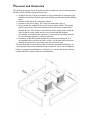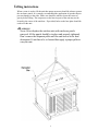
1
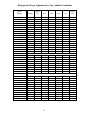
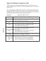
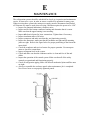
Installation, Commissioning and
Service Manual
Outdoor Condensing
Units
71475-3/3/2006
Contents
A …. Introduction
B …. Installation
2
3
General Safety & Receiving ……………… 3
Placement and Orientation …………..…… 4
Lifting Instructions …….……………….… 5
Electrical Connections ……… …………… 6
Refrigerant Piping …………………..…… 7
Leak Testing …………………………..….. 8
System Evacuation …………………….…. 10
System Charging ………...……………..… 11
Approved Hermetic Compressor Oils ……. 13
C
D
E
F
G
….
….
….
….
….
System Start-Up ……..
Operational Checkout .
Maintenance …………
Trouble Shooting ……
Start-up Information…
1
14
15
16
17
20
A
INTRODUCTION
The purpose of this Manual is to assist the contractor and other interested people in the
proper handling, installation and servicing of Tecumseh Outdoor Condensing Units.
It is of great importance to follow these guidelines to avoid improper installations that
may cause unit failure, poor performance or reduced reliability.
Installation related issues that are not covered in this manual should be approached and
resolved by applying generally accepted criteria and knowledge from the commercial
refrigeration industry.
As the condensing unit is only a part of the refrigeration system it becomes very
important to properly select and employ them in the system.
The refrigeration system should be properly designed, components properly selected and
balanced in order to ensure a reliable performance of the system in general and the
condensing unit in particular.
Poor system design, inappropriate component selection and balance will compromise
condensing unit performance and reliability.
Care should be taken in the purchase of mating components to ensure that these parts are
the best suited to the published performance of the condensing unit. Furthermore, the
cleanliness to the total system installation has a bearing on the reliability and
performance of the condensing unit and its system.
2
B
INSTALLATION
General Safety and Receiving
Installation Codes
The units must be installed in accordance with all applicable national and local codes.
Trained personnel only
The installation and start up, the service and troubleshooting of these condensing units
should be done only by those with the necessary knowledge, training and equipment.
WARNING:
Main power supply should always be disconnected and locked off to
avoid accidental start up or electric shock. Failure to do so could
result in injury or death.
Some parts like condenser fins or some corners on the sheet metal
parts are sharp and may potentially cause injury. Use extra caution
when working around these parts.
Receiving Inspection
The unit should be inspected before unpacking for signs of damage or loss and packing
list should be checked against material received to ensure shipment is complete.
A report should be compiled and a claim must be filed with the freight carrier if shipping
damage is discovered.
If damages to the packing are obvio us but no visible damage on the unit or the parts are
noted then a report should be compiled and a claim for “probable hidden damages”
should be filed with the transportation carrier.
♦ WARRANTY:
The manufacturer is not responsible for damages or loss caused by the
transportation carrier.
3
Placement and Orientation
The decision to properly locate the position of these outdoor air-cooled condensing units
should carefully consider important factors like:
⇒ Weight of the unit. If units are installed on the roof then their weight and weight
distribution should be checked against the building specifications and the building
codes.
⇒ Distance of the unit to the refrigerated cabinet.
⇒ Distance to the power supply. (See electrical connections, page 8)
⇒ Space around the condensing unit and in between adjacent units. This should
consider prevention of the re-circulation of the air and insure enough airflow
through the unit. These distances should also provide enough room around the
units so that enclosure panels may be removed and such that adequate
accessibility is provided to the compressor, electrical boxes and other controls.
Use the following diagram as a point of reference.
⇒ Orientation of the units should consider the prevailing wind direction. It is
recommended not to position the units in such a way that the airflow direction
through the unit faces the prevailing wind direction for the area.
The units should be mounted and secured on adequate rigid and levelled bases, to
avoid improper lubrication conditions for the compressor. Never use the shipment
pallet as a permanent mounting base. If vibration is a concern then proper vibration
isolators should be installed under the mounting base.
4
Lifting instructions
When a crane is used to lift the unit then proper measures should be taken to protect
the enclosure panels. It is strongly recommended the application of spreader bars to
prevent damages to the sides. Some care should be taken to locate the center of
gravity before lifting. The compressor as the heaviest part of the unit may not be
located in the center of the unit base. If provided, holes on the base plate should be
used to lift the unit.
♦ HANDLING
Never lift or displace the outdoor units with enclosure panels
removed. All the panels should be in place and properly tightened.
Don’t remove the shipment pallet until the unit arrives at the final
destination. If unit has to be re-located then apply a proper pallet to
carry the unit.
5
Electrical Connections
All electrical wirings must be done in compliance with all applicable local and
national codes.
Check and verify before any electrical installation if the voltage and phases of the
supply satisfy those required by the nameplate of the unit. In order that these units
have the starting, operating and dependability characteristics required of them, the
compressor and its protective devices are designed for operation within a very
specific minimum and maximum voltage range. This voltage range is defined in the
following table:
Voltage shown on Unit
Nameplate
208-230-60-1
200-230-60-3
Voltage Code
Voltage Range
XD, XN
XT
235 –197
253 – 180
Refer to “Minimum Circuit Ampacity” and “Maximum Fuse Size” data on the unit
nameplate and applicable electrical codes to size the electrical wires, fuses and over
current protection devices.
Refer to wiring diagram (attached inside of the electrical cabinet) to complete unit control
circuit.
A pump down cycle should be employed to control all these units. Solenoid valve for the
liquid line is an option that may be supplied loose and should be field installed by others.
Room thermostat is supplied and installed by others.
The following are some typical wiring diagrams. Generally the wiring diagrams will
show all electrical components, even those that are offered as options or should be
supplied and installed by others. Should any component be added to the unit as a field
supplied option then the wiring should follow the given diagram.
♦ WARRANTY
Any non-compliance with voltage ranges and phase balances or any
altering of electrical components without Tecumseh written approval
will void the warranty.
6
Refrigerant Piping
Standard piping practices and local codes should be employed to size and install
refrigerant gas and liquid lines.
♦ PIPING
Employ only Refrigeration grade copper tubing. Always keep the
tubes free of moisture and dirt and remove any burrs present on the
tubes.
A) The selection of the suction gas line sizes should be guided by the following criteria:
⇒ Assurance of adequate velocity, thus ensuring oil return capability (the tube size
must be limited to maintain velocities no less than 750 fpm for horizontal and
down flow and no less then 1500 fpm for up flow)
⇒ Assurance of acceptable pressure drop (The tube size should be limited to
maintain velocities no greater then 1500 fpm for horizontal and down flow and no
greater then 2500 fpm for up flow.)
⇒ Assurance of satisfactory sound level (the tube size should be limited to maintain
velocities no greater then 3000 fpm.)
Horizontal suction lines should be sloped downward in the direction of the compressor at
least ½” per 10’ of line. A suction trap should be installed at the base of suction risers.
Suction line lengths in excess 100 feet may require additional oil be added to the
compressor.
B) Liquid line sizes are based on pressure drops that will not permit gas formation for
horizontal lengths up to 100’. For lines longer than 100’ horizontal and for lines that
travel up vertically additional sub-cooling must be provided to overcome the vertical
liquid head pressures and extra length. Liquid refrigerant in vertical column will exert a
downward pressure of 0.5 – 0.6 pounds per linear foot of tube, and depending upon the
direction of the refrigerant flow, will either add or subtract from the liquid line pressure
drop.
C) Elbows, valves and reduced joint sizes increase pressure drop and deserve additional
consideration.
D) Long radius elbows should be employed to minimize pressure losses.
E) To prevent oxidation and scale forming inside the tubes it is recommended to flow dry
nitrogen through the tubing during the soldering operations. A light flow of about ¼ CFM
is sufficient.
F) Follow the manufacturer’s instructions when brazing service valves or other parts that
may be damaged by excessive heat.
G) After all leak check procedures (below) are complete, refrigerant lines that may be
exposed to high and low ambient temperatures should be insulated. As a rule of thumb,
suction lines should be insulated with an industry accepted material of no less than ¾”
wall thickness. Liquid lines should also be insulated with at least ½” wall thickness. The
insulating material should be of a kind intended for outdoor use.
7
Pressure testing for leaks
A pressure leak test is mandatory and is to be performed for the complete refrigeration
system, including the condensing unit, prior to system charging.
To thoroughly leak check the system, the system should be pressurized to a maximum of
150 PSIG with dry nitrogen to the high and low side of the system. With the pressure
equalized at 150 PSIG, a leak check should be performed on EVERY joint in the system,
including the condensing unit, to ensure that no major leaks are present. The initial
charge may then be released.
The leak check procedure should then be repeated using a much more accurate means to
determine that the system is 100% free of leaks. Use of electronic leak detection
equipment is highly recommended due to its potential accuracy when used correctly in
accordance with the manufacturers instructions. If trace amounts of refrigerant are used,
use only the refrigerant indicated on the serial label of the condensing unit.
If trace amounts of refrigerant are used during the leak check procedure, this must be
properly recovered and disposed of in an appropriate manner to protect the environment.
As an added precaution, the leak check charge should be left in the system for no less
than 12 hours without loss of pressure.
Every joint in the system including, but not limited to, factory welds, flare nuts and
pressure controls must be leak checked.
A leak free system is required for the installation to function correctly.
♦ System
Flushing, Purging, and Pressure Testing for
Leaks
Failure to properly flush, purge, or pressure test a system for leaks can
result in serious injury or death from explosion, fire, or contact with
acid-saturated refrigerant or oil mists.
Follow these precautions when flushing, purging or pressure testing a system for leaks:
⇒ Use purging products according to the manufacturer’s instructions
⇒ To purge a system, use only dry nitrogen.
⇒ When pressure testing for leaks, use only regulated dry nitrogen or dry nitrogen plus
trace amounts of serial label refrigerant.
⇒ When purging or pressure testing any refrigeration or air conditioning system for
leaks, never use air, oxygen or acetylene.
• Oxygen can explode on contact with oil.
• Acetylene can decompose and explode when exposed to pressures greater than
approximately 15 PSIG.
• Combining an oxidizing gas, such as oxygen or air, with an HCFC or HFC
refrigerant under pressure can result in a fire or explosion.
8
⇒ Use a pressure regulating valve and pressure gauges.
• Commercial Cylinders of nitrogen contain pressures in excess of 2000 PSIG
at 70°F. At pressures much lower than 2000 PSIG, compressors can explode
and cause serious injury or death. To avoid over pressurizing the system,
always use a pressure-regulating valve on the nitrogen cylinder discharge. The
pressure regulator must be able to reduce the pressure down to 1 to 2 Psig and
maintain this pressure.
•
The regulating valve must be equipped with two pressure gauges:
◊ One gauge to measure cylinder pressure
◊ One gauge to measure discharge or down stream pressure
⇒ Use a pressure relief valve.
• In addition to pressure regulating valve and gauges, always install a pressure
relief valve. This can also be frangible disc type pressure relief device. This
device should have a discharge port at least ½” NPT size. The valve or
frangible disc device must be set to 175 Psig.
⇒ Do not pressurize the system be yond 150 PSIG field leak test pressure.
⇒ Disconnect nitrogen cylinder and release the pressure in the system before evacuating
and connecting a refrigerant container.
Nitrogen pressurizing method to be used as a major leaking detector process, more
detailed leak check with refrigerant leak detectors is necessary. Use only serial label
refrigerant for leak detection.
♦
Pressure Controls
Always protect low (or dual) pressure control from excessive high
pressure. It is recommended to disconnect the low-pressure (or the
low side of the dual pressure) control prior to pressurization.
♦ WARRANTY
Follow the leak check procedure very carefully. Warranty will be
voided if compressor fails as a result of refrigerant leakage related
problems. Leakage of refrigerant to the atmosphere has been
identified as a major source of global warming and ozone depletion.
9
System evacuation
Following the pressure testing for leaks, the system must be evacuated.
Use a vacuum pump (not a compressor) to draw a vacuum of 1000 microns or less from
both sides of the system. Do not attempt to draw a vacuum on the system with the pump
connected only on the low side. The high side of the system should be interconnected
with the low side by using a minimum 3/8” OD copper tube. Use a good electronic gauge
to measure the vacuum because a refrigeration gauge cannot provide an accurate reading
at this resolution.
Break the vacuum with dry nitrogen.
Repeat this procedure at least three times. Final vacuum should reach at least minimum
100 microns.
These procedures should be performed at ambient temperature above 65°F. If ambient
temperature is below 65°F then the final vacuum must be 50 microns.
Note the Following:
Never use a compressor to evacuate a system. Instead, use a high pressure vacuum pump
specifically designed for that purpose. Never start the compressor while it is under a
deep vacuum. Always break the vacuum with a refrigerant charge before energizing the
compressor.
Failure to follow these instructions can damage the hermetic terminal. As always, to
avoid serious injury or death from terminal venting with ignition, never energize the
compressor unless the terminal cover is securely fastened.
♦ WARRANTY
Follow the evacuation procedure very carefully. Warranty will be
voided if compressor fails as a result of moisture related problems.
10
Refrigerant Charging
Failure to properly charge the system can result in serious injury or death
from explosion or fire.
Follow these precautions when charging a system
⇒ Do not operate the compressor without charge in the system.
• Operating the compressor without a charge in the system can damage the
hermetic terminals.
• To reduce the risk of serious injury or death from fire due to terminal venting,
never energize the compressor unless the protective terminal cover is securely
fastened.
• After the system has been evacuated, break the vacuum with the specified
refrigerant and proceed to charge the system.
⇒ Use proper refrigerant.
• Use only the refrigerant specified on the serial label when charging the
system. Using a different refrigerant can lead to excess system pressure and an
explosion.
⇒ Do not overcharge a refrigeration system.
,
Overcharging the system immerses the compressor, motor, piston, connecting rods and
cylinders in liquid refrigerant This creates a hydraulic block preventing the compressor from
starting. The hydraulic block is also known as locked rotor.
Continued supply of electricity to the system causes heat to build in the compressor. This heat
will eventually vaporize the refrigerant and rapidly decrease system pressure. If, for any
reason, the thermal protector fails to open the electrical circuit, system pressure can rise to high
enough levels to cause a compressor housing explosion.
It is highly recommended to charge the system into the high side through the process port
provided in the liquid valve. Employ a liquid line drier when charging to ensure clean and
dry refrigerant entering into the system.
If charging through the low side, then the refrigerant should enter in gas form only. Break
the vacuum by allowing refrigerant vapor to enter into the system through the service
suction valve, or Rota Lock adaptor. When the low side pressure reaches 60 PSIG for
R22, start the compressor and continue charging at rate no more than 5 pounds per
minute.
Vapor charging is not allowed for blended type refrigerants. (R404A should always be
charged in liquid form, unless the whole amount of refrigerant from the container is
used.)
♦ WARRANTY
Use of a refrigerant other than those listed on the serial label will void
the compressor warranty.
11
Refrigerant Charge Adjustment for Low Ambient Conditions
Model
Number
Refrig.
Above
70 F
50 F
30 F
10 F
0F
Below
20 F
AKA9459EXDHG
AKA9470EXDHG
AJA9484EXDHG
AWG4518EXNHG
AWG4523EXNHG
AWG4523EXTHG
AWG4525EXNHG
AWG4525EXTHG
AWG4530EXNHG
AWG4530EXTHG
AVA4544EXNHG
AVA4544EXTHG
AVA4547EXNHG
AVA4547EXTHG
AGA4551EXNHG
AGA4551EXTHG
AGA4560EXNHG
AGA4560EXTHG
R-22
R-22
R-22
R-22
R-22
R-22
R-22
R-22
R-22
R-22
R-22
R-22
R-22
R-22
R-22
R-22
R-22
R-22
2.4
3.2
3.2
3.2
4.4
4.4
5.9
5.9
5.9
5.9
13.2
13.2
13.2
13.2
13.2
13.2
16.3
16.3
2.5
3.3
3.3
3.3
4.6
4.6
6.2
6.2
6.2
6.2
13.8
13.8
13.8
13.8
13.8
13.8
17
17
2.6
3.5
3.5
3.5
4.7
4.7
6.3
6.3
6.3
6.3
14.2
14.2
14.2
14.2
14.2
14.2
17.5
17.5
2.7
3.5
3.5
3.5
4.8
4.8
6.5
6.5
6.5
6.5
14.6
14.6
14.6
14.6
14.6
14.6
18
18
2.7
3.6
3.6
3.6
4.9
4.9
6.7
6.7
6.7
6.7
14.9
14.9
14.9
14.9
14.9
14.9
18.3
18.3
2.8
3.7
3.7
3.7
5
5
6.8
6.8
6.8
6.8
15.2
15.2
15.2
15.2
15.2
15.2
18.7
18.7
AJA2423ZXDHG
AJA2436ZXDHG
AWA2444ZXDHG
AWA2481ZXDHG
AWA2481ZXTHG
AVA2511ZXNHG
AVA2511ZXTHG
AVA2514ZXNHG
AVA2514ZXTHG
R-404A
R-404A
R-404A
R-404A
R-404A
R-404A
R-404A
R-404A
R-404A
2.2
2.2
2.2
3.9
3.9
3.9
3.9
5.3
5.3
2.3
2.3
2.3
4.1
4.1
4.1
4.1
5.6
5.6
2.3
2.3
2.3
4.2
4.2
4.2
4.2
5.8
5.8
2.4
2.4
2.4
4.4
4.4
4.4
4.4
5.9
5.9
2.5
2.5
2.5
4.4
4.4
4.4
4.4
6.1
6.1
2.6
2.6
2.6
4.6
4.6
4.6
4.6
6.1
6.1
AKA9464ZXDHG
AWA9512ZXNHG
AWA9511ZXNHG
AWA9511ZXTHG
AWA9513ZXNHG
AWA9513ZXTHG
AVA9522ZXNHG
AVA9522ZXTHG
AVA9532ZXNHG
AVA9532ZXTHG
AGA9539ZXNHG
AGA9539ZXTHG
R-404A
R-404A
R-404A
R-404A
R-404A
R-404A
R-404A
R-404A
R-404A
R-404A
R-404A
R-404A
2.8
5.3
3.9
3.9
3.9
3.9
11.9
11.9
11.9
11.9
14.6
14.6
3
5.6
4.1
4.1
4.1
4.1
12.4
12.4
12.4
12.4
15.3
15.3
3.1
5.8
4.2
4.2
4.2
4.2
12.8
12.8
12.8
12.8
15.8
15.8
3.2
5.9
4.4
4.4
4.4
4.4
13.2
13.2
13.2
13.2
16.3
16.3
3.2
6.1
4.4
4.4
4.4
4.4
13.5
13.5
13.5
13.5
16.6
16.6
3.3
6.1
4.6
4.6
4.6
4.6
13.8
13.8
13.8
13.8
17
17
12
Approved Hermetic Compressor Oils
Hermetic compressors are charged with optimum oil that will be adequate for closecoupled systems designed in accordance with good engineering practice. (See refrigerant
piping, page 14)
Some system designs containing unusual evaporators or extensive interconnecting pipes,
may require additional oil. However since excess oil can also damage compressors, care
should be taken not to exceed the oil charge amounts specified. If the correct oil charge is
in doubt, please obtain assistance from your Krack sales engineer.
Compressor
Refrigerant
Approved Compressor Oils
R-22
Napthenic, Synthetic, Napthenic/Paraffinic
AKA
Witco-Suniso 3GS, Shrieve Chemical Zerol 150TD
Witco-LP200, Penreco Sontex 200LT
AJA
Witco-Suniso 3GS, Shrieve Chemical Zerol 150TD
AWG
Witco-Suniso 3GS, Shrieve Chemical Zerol 150TD
Witco-LP200, Penreco Sontex 200LT
AVA
Witco-Suniso 3GS, Shrieve Chemical Zerol 150TD
Witco-LP200, Penreco Sontex 200LT
AGA
Shrieve Chemical Zerol 300, Penreco Soltex SA-68
Witco-LP200, Penreco Sontex 200LT
R-404A
Polyol Ester (with approved additives)
AKA, AJA,
AWG, AVA
AGA
Witco-Suniso SL32, SL22; Penreco Sontex SEZ32,
SEZ-22; Castrol Inc. Icematic SW-32; Mobil EAL
Arctic 32, 22; Emery 2927-A; ICI Emkarate RL32S
13
C
System Start-Up Procedure
⇒
⇒
⇒
⇒
⇒
⇒
⇒
⇒
⇒
⇒
Check the electrical connections if they are properly attached and secured.
Check the electrical supply versus nameplate specifications.
Check if the Voltage deviation is within the specified range.
Check all mechanical and electrical connections if they are properly tightened and
secured. Compressor mounting parts, fan motor mounting screws, fan blade
tightening screw, shroud electrical boxes etc.
Check that the safety and pressure controls are connected and set correctly.
Check that the suction and liquid valves are open.
Check by isolating the compressor motor if the control circuit including
thermostat and solenoid valve(if used) is wired and operates correctly.
Confirm that the system has been properly leak tested, evacuated and charged. If
not, then follow the leak testing, evacuating and charging procedures described
respectively at “Pressure testing for leaks”, “System evacuation” and “Refrigerant
charging”. If the system has been previously charged then make sure that the
crank case heater is turned on at least 24 hours prior to start up, otherwise
warm up the compressor bottom shell to assure that the refrigerant will not cause
damage to the compressor due to the slugging condition. Do not attempt to warm
up the compressor by applying a flame to the crankcase.
Turn on the electrical power to the condensing unit and unit cooler(s) or
freezer(s). The compressor will start when the low-pressure control closes.
Always re-assemble the enclosure panels when start- up job is completed. Never
leave loose or not properly tightened panels.
14
D
Operational checkout procedure
⇒ Check if the Voltage deviation is within the specified range.
⇒ Check that the ampere draw doesn’t exceed the amperage specified on the
nameplate.
⇒ Check the phase unbalance if there is a three-phase connection. Unbalance
should not exceed 2%
⇒ Check that the discharge and suction pressures are within the allowable design
limits.
⇒ Check the liquid flow in the liquid sight glass.
⇒ Measure compressor and evaporator superheats. Make proper adjustments if
necessary.
⇒ Check the high-pressure control setting by simulating a condenser block, shutting
off the fans and observing with extreme caution the pressure rise.
⇒ Check the low-pressure setting by simulating a pump-down cycle. Observe the
cut-off pressure, and adjust according to the table below.
⇒ Check (if equipped) the defrost and timer controls for proper initiation and
termination settings.
⇒ If any malfunction is observed at any time during either start-up or operational
checkout procedures, stop the unit, disconnect power and correct the malfunction
accordingly.
⇒ Re-check after 48 hours of operation for loose electrical connections, abnormal
vibrations that may have developed, refrigerant charge and correct any probable
malfunction observed.
⇒ Always re-assemble the enclosure panels when operational check out procedure is
completed. Never leave loose or not properly tightened panels.
Minimum
Temperature
50 F
40 F
30 F
20 F
10 F
0F
-10 F
-20 F
Low Pressure Control Settings
R22
R404A
Max Cut In Max Cut Out Max Cut In Max Cut Out
70 PSIG
30 PSIG
85 PSIG
40 PSIG
55 PSIG
25 PSIG
70 PSIG
35 PSIG
40 PSIG
20 PSIG
50 PSIG
30 PSIG
30 PSIG
10 PSIG
40 PSIG
20 PSIG
20 PSIG
5 PSIG
30 PSIG
10 PSIG
15 PSIG
0 PSIG
25 PSIG
5 PSIG
10 PSIG
0 PSIG
15 PSIG
0 PSIG
8 PSIG
0 PSIG
10 PSIG
0 PSIG
⇒
15
+ Temperature is the
minimum ambient
temperature at the
condensing unit or the box
design temperature
whichever is lo wer.
Example #1 30 F minimum
ambient, -20 F freezer.
Use
-20 F value from the table.
Example #2 -10 F
minimum ambient, 35 F
cooler. Use the –10 F
value from the table.
E
MAINTENANCE
The refrigeration systems should be scheduled for check- up, inspection and maintenance
service, at least twice a year, in order to assure a trouble free operation for many years.
When servicing these systems the main power supply must be disconnected and locked
off. Extreme care must be used when servicing a unit that requires the power to be “ON”.
⇒ Inspect for abnormal indications, vibration, noise.
⇒ Inspect and feel the bottom crankcase housing and determine that it is warm.
Make sure that the upper housing is not sweating.
⇒ Inspect all electrical parts for loose connections. Tighten them if necessary
⇒ Inspect insulation status of all wires.
⇒ Inspect contactors and make sure that they are functioning correctly.
⇒ Inspect the fan motors, make sure that the fan blades are tight and all mounting
joints are tight. Refer to the figure below for proper positioning of the fan on the
motor shaft.
⇒ Check the crankcase and receiver heaters for proper operation. Use an ampere
meter to check for current draw.
⇒ Inspect refrigerant level in the system.
⇒ Check and make sure that the condenser surface is clean and free of dirt and
debris.
⇒ Inspect the operation of the control system. Make sure that all of the safety
controls are operational and functioning properly.
⇒ Check all refrigeration piping. Make sure that all mechanical joints and flare nuts
are tight.
⇒ Always re-assemble the enclosure panels when maintenance job is completed.
Never leave loose or not properly tightened panels.
16
F
TROUBLE SHOOTING
This trouble-shooting chart is not designed to replace the training required for a
professional refrigeration service person, nor is it comprehensive.
As a trained professional, for your safety and others always be aware of the following
issues:
⇒ Terminal venting and Electrocution
⇒ Properties of refrigerant and other chemicals involved
⇒ Proper compressor removal methods
⇒ Proper system flushing, purging and leak testing methods
⇒ Proper system charging methods
⇒ Proper system evacuation method
⇒ Start capacitor overheating issues
17
Complaint
1
2
Compressor starts and runs, but
short cycles on thermal protector
3
4
5
6
1
2
Unit runs OK, but run cycle is
shorter than normal (due to
components other than thermal
protector)
3
1
2
Unit operates long or continuously
3
4
5
6
7
1
Space or cabinet temperature too
high
2
Possible Causes
Too much current passing through thermal protector
a Extra sources of current draw
b Compressor motor has winding shorted
Low voltage to compressor (single phase) or
unbalanced voltage (three phase)
Compressor electrical problems, such as thermal
protector or run capacitor not working properly
Discharge pressure too high
Suction pressure too high
Return gas too warm
System component not functioning properly
(thermostat, control contactor)
High pressure cut - out due to:
a Insufficient air supply
b Overcharge of refrigerant
c Air in the system
Low pressure cut - out due to :
a Liquid line solenoid leaking
b Under charge of refrigerant
c Restriction in expansion device
Under charge of refrigerant
System component such as thermostat or contactor not
functioning properly , or control contacts stuck or
frozen closed.
Refrigerated space/cabinet has excessive load or poor
insulation, or system inadequate to handle load
Evaporator coil iced
Restriction in refrigeration system
Dirty condenser
Dirty filter
System problems such as:
a Control setting too high
b Expansion valve too small
c Cooling coil too small
d Inadequate air circulation
Refrigerated space has excessive load or poor
insulation or system may be inadequate to handle
load
18
Possible causes
Complaint
1
Compressor will not start-no hum
2
3
4
5
6
1
2
3
Compressor will not start - hums
but trips on thermal protector
4
5
6
1
2
3
Compressor starts but does not
switch off of start winding
4
5
Liquid line frosted or sweating
Suction line frosted or sweating
System component not functioning properly
a Control/contactor stuck in open position
b Thermostat not functioning properly
c Control is off
Line disconnect switch is open
Circuit breaker tripped or fuse open or removed
Thermal protector not working properly
Wiring improper or loose
Compressor motor has a ground fault (short circuit)
Improperly wired
Low voltage to compressor
System component not functioning properly
(thermostat, control contactor)
Compressor electrical problems
a Compressor motor has a winding open or
shortened
b Start capacitor not working properly
c Relay does not close
Liquid refrigerant in compressor
Internal mechanical trouble in compressor
Improperly wired
Low voltage to compressor
Compressor electrical problems
a Compressor motor has a winding open or shorted
b Relay fails to open
c Run capacitor not working properly
Discharge pressure too high
Internal mechanical trouble in compressor
1 System problems such as, restriction in filter drier
or strainer or liquid shut - off partially closed
1 System problems such as:
a Expansion valve passing excess refrigerant
b Expansion valve stuck open
c Evaporator fan not running
d Overcharge of refrigerant
19
G
Start-up Information
Important: This start-up information should be completely filled in for each installation
and remain with the unit as a permanent record for future reference. Future service work
may be logged on the proceeding page.
Name & address of installation_______________________________________________
________________________________________________________________________
Name, address, phone & fax # of Installing contractor ____________________________
________________________________________________________________________
________________________________________________________________________
Type of System (Cooler, Freezer, etc…) ____________________
Design Box Temperature _____°F
Condensing Unit System start-up date ______________________
Unit model # __________________________________________
Unit serial # ___________________________________________
Compressor model #_____________________________________
Compressor serial #______________________________________
Evaporator(s) Manufacturer _______________________________
Evaporator(s) QTY ______
Expansion valve - Manufacturer________________________________
Expansion Valve Model # ____________________________________
Leak Check Procedure: ______________________________________Unit leak check
by: ________________________________________________
Company: ____________________________________Date:_______________
Refrigerant Type ________ Total Charge ________
System evacuation # of times______
Final micron _______
Ambient at start-up ______ºF
Operating box temperature ______ ºF
Thermostat setting ______ ºF
Defrost settings ______ / day Minutes fail safe ______
Condensing unit electrical rating: Volts __________ Phase __________ Hz _________
Voltage at compressor terminals: L1/L2_________ L2/L3 ________ L1/L3__________
Amperage at compressor: L1___________ L2 ____________ L3 ___________
Compressor discharge pressure __________ psig
Compressor suction pressure __________ psig
Discharge line temperature at compressor______ ºF
Suction line temperature at compressor______ ºF
Superheat at compressor ___ ºF
Suction line temperature at evaporator TX valve bulb______ ºF
Superheat at evaporator______ ºF
20
Comments:
21