1
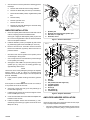
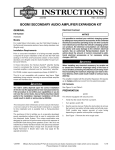
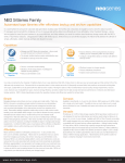
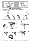
-J05996
REV. 2014-11-14
BOOM! AUDIO STAGE II TOUR-PAK AMPLIFIER INSTALLATION KIT
Electrical Overload
GENERAL
Dealer installation is recommended. Radio EQ update using
the Digital Technician® II diagnostic tool is:
•
Recommended before speaker INSTALLATION
•
Required before audio system OPERATION.
•
Only available through authorized Harley-Davidson
dealers.
Kit Number
76000585
Models
For model fitment information, see the P&A retail catalog or
the Parts and Accessories section of www.harley-davidson.com
(English only).
Installation Requirements
This kit must be installed:
•
Before installation of the Boom! Audio Stage II Tour-Pak
Speaker Kit (Part No. 76000526).
•
After installation of a PRIMARY fairing-mounted amplifier.
The amplifier (Part No. 76000277A) installed with this kit must
be purchased separately from a Harley-Davidson dealer.
FLHX, FLHXS and FLHXSE models require installation of an
original equipment (OE) rigid Tour-Pak Mounting Rack. See a
Harley-Davidson dealer for the correct parts, available separately. Install per the service manual.
ALL models: If installing more than TWO amplifiers, an
AUDIO IN Three-Way Y-Connector (Part No. 69201092) AND
a Battery+ Three-Way Y-Connector (Part No. 70270-04A) are
needed. Purchase separately from a Harley-Davidson dealer.
The rider's safety depends upon the correct installation
of this kit. Use the appropriate service manual procedures.
If the procedure is not within your capabilities or you do
not have the correct tools, have a Harley-Davidson dealer
perform the installation. Improper installation of this kit
could result in death or serious injury. (00333a)
NOTE
This instruction sheet references service manual information.
A service manual for this year/model motorcycle is required
for this installation. One is available from a Harley-Davidson
dealer.
-J05996
It is possible to overload your vehicle's charging system
by adding too many electrical accessories. If the combined
electrical accessories operating at any one time consume
more electrical current than the vehicle's charging system
can produce, the electrical consumption can discharge
the battery and cause damage to the vehicle's electrical
system. See an authorized Harley-Davidson dealer for
advice about the amount of current consumed by additional electrical accessories or for necessary wiring
changes. (00211c)
When installing any electrical accessory, be certain not
to exceed the maximum amperage rating of the fuse or
circuit breaker protecting the affected circuit being modified. Exceeding the maximum amperage can lead to electrical failures, which could result in death or serious injury.
(00310a)
The amplifier installed with this kit requires up to 8 amps
more current from the electrical system.
Kit Contents
See Figure 4 and Table 1.
PREPARATION
To prevent accidental vehicle start-up, which could cause
death or serious injury, remove main fuse before proceeding. (00251b)
Disconnect negative (-) battery cable first. If positive (+)
cable should contact ground with negative (-) cable connected, the resulting sparks can cause a battery explosion,
which could result in death or serious injury. (00049a)
NOTE
•
WITH security siren: With security fob present, turn
ignition switch ON. See the service manual. Disarm
security system. IMMEDIATELY remove the main fuse.
•
WITHOUT security siren: See the service manual.
Remove main fuse. Turn ignition switch OFF.
Many Harley-Davidson® Parts & Accessories are made of plastics and metals which can be recycled.
Please dispose of materials responsibly.
1 of 4
1.
See the service manual to perform the following generalized steps:
is08515a
a.
Remove seat. Retain all seat mounting hardware.
b.
Remove the ECM caddy from the top of the battery.
c.
Disconnect both battery cables, negative battery cable
first.
d.
Remove battery.
e.
Remove right side cover.
f.
Remove left side cover.
2
g.
Remove the two bolts attaching the electrical caddy
under the left side cover.
4
1
AMPLIFIER INSTALLATION
1.
1.
2.
3.
4.
Clean the capacity label inside the Tour-Pak with a 50-50
mixture of isopropyl alcohol and distilled water.
See Figure 4. Apply the new capacity label (13) from the
kit to cover the original label. Note the revised load limit
due to the amplifier installation.
2.
Install the brackets (4 and 8) to amplifier (A) with screws
(6). Alternately tighten to 84-108 in-lbs (9.5-12.2 N-m).
3.
Remove all items from Tour-Pak®. Remove Tour-Pak.
Remove Tour-Pak liner (if present). Place Tour-Pak on a
protected surface.
•
Speaker pod
Existing hole and grommet, speaker pod
New hole, 1.0 in (25 mm)
Grommet, round
Figure 1. Grommet Installation
is08513a
1
2
3
4
1
NOTES
Disconnect and remove speakers from speaker pods to
avoid damage to wiring inside.
•
Use of a step drill bit is recommended to prevent damage
to the speaker pod covering.
4.
See Figure 1. Drill a new 1.0 in (25.4 mm) hole (3) in each
speaker pod (1), away from the existing grommet (2),
approximately where shown.
3
3
4
5
5
7
NOTE
These holes are for leads [36TB] and [37TB] of the amplifier
harness (Figure 4, Item 3), which are connected during
installation of the Boom! Audio Stage II Tour-Pak Speaker Kit
(Part No. 76000526).
5.
3
8
7
8
Lightly sand the speaker housings around the grommet
holes.
1.
2.
3.
4.
5.
6.
7.
8.
NOTE
If the amplifier is installed before the Tour-Pak is mounted, it
is not possible to secure the Tour-Pak.
6
6
Nut (4)
Tour-Pak
Hex pocket, Tour-Pak support (4)
Tour-Pak support
Amplifier bracket
Screw (4)
Flat washer (4)
Lockwasher (4)
6.
See Figure 2. Place hex nuts (1) into hex pockets (3) on
the Tour-Pak support (5).
7.
Install Tour-Pak. See the service manual. Tighten screws
to 60-72 in-lbs (6.8-8.1 N-m).
8.
Cover the rear fender with a towel. Slide the amplifier with
brackets in from the side.
AMPLIFIER HARNESS INSTALLATION
9.
Install the amplifier. Secure with flat washers (7), lockwashers (8) and screws (6). Tighten screws to 60-72 inlbs (6.8-8.1 N-m).
These tips help make sure all wiring fits under the seat, especially in multiple amplifier installations:
Figure 2. Amplifier Installation
NOTES
•
-J05996
See Figure 3. Begin routing the amplifier harness from the
large 23-way connector [149] (1), moving forward on the
2 of 4
vehicle.The large connector does not fit through narrower
passages.
•
Route the remainder of the harness forward on the vehicle
through the space between the Tour-Pak support (3) and
fender (4).
•
Route all wire harnesses under the frame rail to avoid
pinching by cover or seat.
•
Connections [36TB] (right pod speaker) and [37TB] (left
pod speaker) are connected during installation of the
Boom! Audio Stage II Tour-Pak Speaker Kit (Part No.
76000526).
•
Take care to route ALL amplifier harness branches away
from spark plug wires. Close proximity induces spark noise
into the audio system.
•
When routing wires from right to left sides of the vehicle,
tuck harnesses under the frame tray behind the battery.
Keep the battery compartment accessible.
•
Route the six-way black, pink-wired audio connectors
under the right frame rail, into the right side cover. Bundle
in front of ABS module, if present.
•
Route the six-way, gray DLCs along the left frame rail.
Bundle the connectors in a pocket in the frame in front of
the battery, under the wire trough along the frame backbone.
•
2
1
3
4
1.
2.
3.
4.
23-Way connector [149]
Amplifier harness
Tour-Pak support
Rear fender
Figure 3. Harness Routing
DATA LINK CONNECTOR (DLC)
RELOCATION
1.
Locate the black, four-way Molex connector [296A] near
the back of the underseat area.
Locate the gray six-way Data Link Connector (DLC) [91A]
in the electrical caddy. Cut the tether attaching the rubber
plug around the harness.
2.
FLHX/FLTRX models: On a jumper harness coming from
the fairing.
Pull connector [91A] back through the electrical caddy to
a location under the seat, behind the caddy.
3.
See Figure 4. Plug in socket connector [91B] on the
amplifier harness (6) to connector [91A] under the seat.
FLHTCU/FLHTK models: On an adapter harness with
two 16-way ([162C] and [162D]) and two four-way ([296A]
and (297B]) connectors.
With ONLY ONE Stage II amplifier installed in the rear:
Remove the plug in the [296A] connector. Connect the
amplifier harness.
With TWO or more Stage II amplifiers installed in the
rear: Plug the audio input harness (Part No. 69201092,
purchased separately) into connector halves [296A] and
(297B] on the interconnect harness (2). Plug amplifier
harness (3) connector [296A] into the audio input harness.
•
is08517
Confirm that the amplifier harness connectors and harness
routing are clear of all moving parts.
•
Route the battery terminal branch to the battery terminals,
but DO NOT connect the battery cables now.
•
If more than two amplifiers or other accessories already
use the ground post of the battery, use one of the frame
ground studs.
•
If more than two amplifiers are installed on the vehicle, a
Battery+ Three-Way Y-Connector (Part No. 70270-04A,
available separately) is required.
•
Once routing is finalized, secure with cable straps (10)
and retainers (1).
-J05996
NOTE
The amplifier harness gray six-way pin connector [91A]
replaces the original equipment (OE) connector [91A] in the
electrical caddy.
4.
Route the new pin connector [91A] under the seat, and
into the electrical caddy.
5.
Insert the rubber plug removed in Step 1 into the new pin
connector [91A]. Use a cable strap (10) from the kit to
attach the tether to the harness.
COMPLETION
NOTE
To prevent possible damage to the sound system, verify that
the ignition switch is OFF before attaching the battery cables.
Connect positive (+) battery cable first. If positive (+) cable
should contact ground with negative (-) cable connected,
the resulting sparks can cause a battery explosion, which
could result in death or serious injury. (00068a)
1.
Install battery. See the service manual.
3 of 4
2.
3.
See the service manual. Connect the battery terminal
branch to the battery terminals (red positive cable first).
a.
Position the + ring terminal onto the positive battery
terminal. Install the bolt.
b.
Position the in-line fuse holder in a location that can
be easily accessed.
c.
Position the - ring terminal onto the negative battery
terminal. Install the bolt.
d.
Tighten both bolts to 60-70 in-lbs (6.8-7.9 N-m).
Install the electrical caddy under the left side cover with
the two bolts removed earlier. Tighten both bolts to 72-96
in-lbs (8.1-10.8 N-m).
is08514
12
10
7
1
6
4.
Install the ECM caddy per the service manual.
5.
Apply a light coat of petroleum jelly or corrosion retardant
material to battery terminals.
After installing seat, pull upward on seat to be sure it is
locked in position. While riding, a loose seat can shift
causing loss of control, which could result in death or
serious injury. (00070b)
6.
See the service manual. Install seat.
7.
See the service manual. Install the main fuse.
SERVICE PARTS
[162B]
[149B]
[36TB]
RH
3
2
[162A]
4
[297B]
[296A]
[B+]
[296B]
8
[37TB]
LH
[297A]
A
6
11
5
[B-]
[91B]
9
[91A]
Figure 4. Service Parts, Amplifier Installation Kit
Table 1. Service Parts
Item
Description (Quantity)
Part Number
1
Bracket, wire retainer (4)
69200342
2
Wire harness, speaker interconnect
69200714
3
Wire harness, Tour-Pak Amplifier
Not sold separately
4
Amplifier bracket
Not sold separately
5
Capscrew (4)
2551W
6
Screw (4)
926
7
Grommet, round (2)
12100073
8
Amplifier bracket
Not sold separately
9
Lockwasher (4)
7036
10
Cable strap (6)
10006
11
Flatwasher (4)
6703
12
Nut (4)
10100065
13
Capacity label (not shown)
14001001
Item mentioned in text, but not included in kit:
A
-J05996
Amplifier
4 of 4