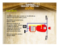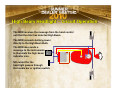
1
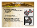
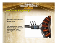
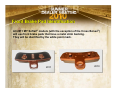
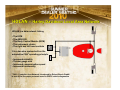
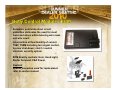
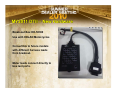
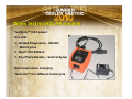
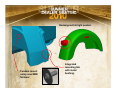
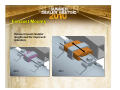
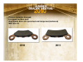
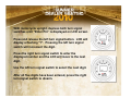
2011 MY
New Model Technical Forum
Bar Codes Added to Frame Labels
Bar codes have been added to the frame labels on all models. The small code
is the PN for the label, the large is the motorcycle VIN.
DO NOT Use caustic cleaners (brake clean) on these labels as the printing
may fade.
VIN
BIG TWIN POWERTRAIN CHANGES
BIG TWIN POWERTRAIN
• Bushing-less cam plate
• Bushing-less rods (running change)
• New induction module / throttle body
• Retainers added for right main bearing
• New breather assembly in the head (running change)
• New bearing in clutch hub
• New compensator for all Touring models
Cam Plate Change
• Bushing removed from
crankshaft bore
• Diameter of crankshaft and ID
of bore remain unchanged
2010
• Service cam plates for all
engines will not have bushing
2011
Connecting Rod
2010
• All dimensions for the piston pin
bore are the same
• All service replacement flywheel
assemblies will use these rods
• This bore will be honed to size
rather than being cut to size
• The upper taper is forged rather
than cut
2011
Throttle Body Changes
FL Throttle body is now die cast
• Die cast body more compact than the old one
Will not retro fit
• New fuel lines
• Smaller Throttle Control motor housing
• New calibrations required
Dyna® and Softail® Throttle bodies
Two ports on the top left of throttle body
• The gray is for Softail® (active purge)
• The black is for Dyna® (passive purge)
• Capped on models not requiring purge system
Right Main Bearing Retainer
• Two screws added to prevent
bearing movement (1)
2
• Case height reduced for clearance
on area surrounding bearing (2)
• Installed depth of bearing in case
changed
• There will be a spacer available for
the service tool to install this bearing
to the correct height
• Do not use the screws to press the
bearing in place
• The bearing support tool needs to
have a small chamfer added to the
OD to clear the bolt boss
1
2011
2010
Engine Breather
• Breather assembly is retrofitable
• No gaskets are available
• New torque specification for
bolts
• The bolts used are a different
length
• Breather is replaced as an
assembly and will be part of the
gasket sets.
Clutch Hub Bearing
• New narrow bearing
• Changes to clutch basket
and snap ring groove
• Retrofits back as an assembly
• Used on all OE configurations
2011
2010
Compensating Sprocket Assembly
All Touring models will now use
the CVO™/ Trike / FXCWC / SE
compensator sprocket design
New Stator Plug Design
The stator connector uses
three O-rings
Two are oil seals and the
third is to keep water and
contaminants from
entering the bore in the
case
2011 Sportster®®
• 883 Front sprockets
•Change from 28T (40379-04) to 29T (40409-04) on all
883 engines
•Belt changes to 137 tooth (40591-07)
• Longer clutch cable length
•Two cables will service all models
• Lower rocker box gasket
• Stator plug material change
• Jiffy stand mount on frame changed for lean angle
Lower rocker box gasket
The formed bead height on the gasket
is increased to provide increased
sealing ability
Gasket part number will not change
}
Bead
height
increased
in this
area
}
XR 1200X™
Fully adjustable premium
front and rear suspension
components by Showa®.
Blacked-out powertrain
with satin black exhaust system.
Nissin® dual front
brakes feature
292mm full-floating
rotors and fourpiston calipers.
The rear shocks use a 36mm
piston with piggy-back
nitrogen charged reservoir.
The compression damping is
adjusted with a knob on top of
the reservoir. Rebound is
adjusted with a thumb wheel
on the lower clevis. Rear
spring pre-load is also
adjustable using the cam
ramp.
XR 1200X Front Fork Detail
Compression and
rebound damping
adjusters on top of fork.
Spring preload
and rebound
damping
adjusters on
top of fork.
Rod guide part
of the cartridge
Compression
damping adjuster
on lower fork
Rod guide supported
by lower tube
Inner cylinder
Eliminated
Compression
valving piston
Eliminated
Conventional Design
Compression and
rebound damping
valves part of main
piston
Showa® Big Piston Design
Spring preload adjuster on
bottom of fork.
SuperLow™
Custom tank no console
New graphic silk screen
4.5 / 1 gal. – 17 / 3.8 liter
Rear shocks
2.5” travel
New seat 883L
25.5” (DOM)
(.6” more than 883L)
New fork bracket spacing and split offset.
Steering head angle 310
Fork angle 29.60
New handlebar
Trail 5.7”
39mm front fork
4.1” travel
(.5” more than 883L)
Front Wheel 18“ x 3.5“
120/70 ZR Radial Tire
New 5
spoke cast
wheels
Rear wheel 17"x 4.5“
150/60 ZR Radial Tire
Michelin®
tires
2011 Dyna®®
Dyna® Changes
• 2011 Cross Platform Projects:
- Bushing-less cam support plate
- Bushing-less connecting rods
- Right main bearing retention
- Clutch bearing change
2011 Softail®®
New for 2011
• Anti-Lock Braking System (ABS) option
• Evaporative canister location
• Sealed hand control switches with new functions.
• Use HDLAN (CAN) bus technology
• Trip function selection control moved to hand controls
• Hazard light control moved to hand controls
• Body Control Module (BCM)
•
•
•
•
•
Replaces most fuses and relays and TSM or HSFM
Eliminates high current loads on ignition and other switches
Reduces wire gauge and harness bundle size
Permits the use of LED turn signals without extra module
Integrates security system and all lighting system functions
Anti-Lock Braking System - ABS
Individual ABS hydraulic control
units (HCU) for front and rear
brakes.
HCU
ECU
Single Electronic Control Unit
(ECU) for system control.
The splash guard, frame and
swingarm have been changed to
accommodate the new routing
and mounting needs of the
components.
ABS models use the encoded
wheel bearings on the sensor
side of the wheel.
HCU
Front Brake Pad Identification
All 2011 MY Softail® models (with the exception of the Cross Bones®)
will use front brake pads that have a metal shim backing.
They will be identified by the white paint mark.
2011
2010
Active Purge for Fuel Tank – (CAL
(CAL and
and some
some HDI
HDI Markets)
Markets)
To provide room for the Hydraulic
Control Unit for the ABS system the
evaporative canister has been
relocated to behind the inner primary.
The line is now controlled by a
solenoid purge valve assembly.
The fuel tank has been reshaped to
accommodate the new system.
Solenoid
operated
purge valve
Charcoal
Canister
HDLAN – Harley-Davidson Local Area Network
HDLAN is a data network linking
• The ECM
• The ABS ECU
• The Body Control Module (BCM)
• The instrument cluster
• The right and left hand controls
E
C
M
It is a two wire system built on the
automotive CAN1 operating principle.
• Increased reliability
• Thinner gauge wire
• Increased communication speed
• Increased functionality
1
E
C
U
CAN – Controller Area Network, introduced by Robert Bosch GmbH.
Is one of the five major protocols used in OBD-II vehicle diagnostics
New Hand Controls
Switches generate HDLAN
messages rather than make
circuit connections.
Trip mode and hazard light
control added.
Ground spring or ground wire
eliminated.
Body Control Module - BCM
Automatic solid state short circuit
protection eliminates the need for most
fuses and relays while reducing wire mass
and wire count.
Incorporates all functionality of current
TSM / TSSM including turn signal control,
tip-over shut-down; clutch / neutral
interlock; security system.
BCM directly controls; Horn, Head Light,
Starter Solenoid, P&A Power.
Caution!
Special procedure used for replacement,
refer to service manual.
Operation
The BCM and all other modules on the HDLAN are
always connected to battery power.
The BCM is connected to the
ignition switch.
When the resistance of
the ignition switch changes
to 200Ω the BCM will
assume the ON mode and
all HDLAN components
will communicate status.
Accessory switch position
will have 800Ω .
E
C
M
E
C
U
High Beam Headlight – Circuit Operation
The BCM receives the message from the hand control
unit that the rider has selected High Beam.
The BCM connects battery power
directly to the High Beam Bulb.
The BCM also sends a
message to the instruments
to illuminate the high beam
indicator icon.
E
C
M
E
C
U
NO current for the
head light passes through
the handle bar or ignition switch.
System Features
Trip Switch Control
• Located on the left hand controls for easy
access and operation while vehicle is on the
road.
High/ Low Beam operation
• High/Low beam switch is momentary contact
switch.
• If high beam bulb fails the system automatically
turns the low beam ON.
• If High/Low beam switch fails, the system
automatically switches to low beam ensuring
legal operation of the vehicle at all times.
Horn Control
• Horn activation is limited to 10 seconds per
activation to prevent horn damage.
Hazard Lights
• Dedicated hazard light switch on right hand controls.
No need to hold both turn signal buttons in.
Turn Signal Control
• Each turn signal bulb is powered individually, this
allows for low current LEDs to be used as turn signal
bulbs with out converters.
• A short circuit in one of the bulbs (front or rear) does
not render the other bulb inoperative.
Run/Stop Switch
• Run/Stop switch status is communicated via the
HDLAN bus.
• Separate wire leads to the BCM as a back up in case
the HDLAN bus fails.
Vehicle Tip-Over functionality
• If vehicle is tipped over, all vehicle power with exception of running lights
is shut down. (currently only engine is shut down, all electrical circuits
remain ON)
Starter Control
• Limits starter activation to 10 seconds at a time to prevent starter from
overheating.
• Disables Starter Activation while engine is running.
• Turns OFF head light and all non-essential vehicle loads during cranking.
Protection for polarity and over voltage conditions:
• If battery connections are reversed the horn will sound to indicate reversal
of the battery polarity.
• If voltage higher than 18vdc is applied, the BCM will not power up the
vehicle to protect the system from damage.
Odometer Display
•
•
Bigger, 16 segment ( 7 segment currently) LED display for better
readability and allowing the display of more characters.
Individual indicator lamps for diagnostic codes.
1. Body Control Module
2. ABS ECU
3. ECM
4. Low Fuel – flashes to indicate sending unit code
4
1
3
1
4
2
Softail®
3
2
CVO™ Softail®
Diagnostics and Fail-enable improvements:
• Diagnostics expanded to include most electrical circuits.
• 130 new Diagnostics Trouble Codes were added allowing for faster and
more accurate diagnostics of system problems.
• Ability to maintain vehicle functionality and safety when certain system
failures occur that currently results in either vehicle shut down or loss of
multiple vehicle functions.
• All power outputs are short circuit protected and self-recover once the
short is repaired.
P&A Provisions:
• Separate 15A constant battery circuit for P&A accessories.
• Separate 15A solid state driver with automatic protection for P&A devices.
• Both circuits are available in the diagnostics connector for easy access.
Digital Technician® II
MY2011 – Softail® Models with
HDLAN
MY2011 DTII – New Hardware
Vehicle Diagnostic Cable,
HD-48650-9
Included with DTII Software
Has a second connector for
use on 2011 Softail® models.
MY2011 DTII – New Hardware
Break-out Box HD-50390
Use with HDLAN Motorcycles
Convertible to future models
with different harness leads
from breakout.
Meter leads connect directly to
box test ports.
When testing HDLAN models
Guided Diagnostics
TechLink™ II AC power:
Use with:
1. Guided Diagnostics - HDLAN
Motorcycles
2. Buell 1125 Reflash
3. Fuel Pump Disable – Vehicle Setup
Disconnect when changing
TechLink™ II to different motorcycle.
New Functions
MY2011 – Softail® Models with
HDLAN
New Icons – Status Area
Turns Fuel Pump OFF
NOTE: Fuel Pump is temporarily disabled. It will turn ON by navigating
to other screens, using Active Diagnostics, cycling ignition, or loss of
TechLink™ II communication with motorcycle.
Toggles Headlamp OFF/ON
NOTE: Headlamp will turn ON by navigating to other screens, using
Active Diagnostics, cycling ignition, or loss of TechLink™ II
communication with motorcycle.
Guided Diagnostics
New
Guided Diagnostic Information
DTC currently displayed.
DTC's’ are diagnosed in the
order of importance as in
prior model years.
Each possible cause will be
‘grayed out’ if a measurement
indicates that it is not a
probable cause for the DTC to
be set.
Guided Diagnostics
New
Guided Diagnostic Information
Test Conditions:
Shows the pre-conditions required
to make a measurement as
displayed on the current screen.
Module Replacement Guidelines: HDLAN Motorcycles
Replacing a BCM - Perform the following from Toolbox\Vehicle Setup:
Set PIN
Module Replace (eliminated 10 minute wait)
BCM Customization tab
Set ABS configuration (installed or not installed)
BCM Turn Signal Customization
Remote Immobilization (Brazil only)
Program FOBs
BCM Customization\Lighting tab
Set Running Light Configuration
Set Stop-Turn-Tail Lamp options
Vehicle Setup
BCM Customization
Toolbox
New –Features
Service Mode
Sidecar / Triglide
ABS
Remote Immobilization:
3rd party security
hardware Installed
(Brazil only).
Warning:
DO NOT SELECT when Remote Immobilization hardware is NOT installed.
It will disable the motorcycle.
Vehicle Setup – Lighting Setup
Lighting Tab
Follow steps when BCM
is replaced or turn signals
are relocated.
Stop-Turn-Tail Lamp
Option
Running Light
Configuration:
Set running light to ON
or OFF while IGN is in
Accessory Position
Vehicle Setup –
Configures ABS
Tell Tale lamp
when replacing
Speedometer or
Tachometer
Vehicle Setup – Keyless Operation
Configures BCM to for
Keyless Operation
Note: If accidentally
configured to “keyless”
on motorcycle with
ignition switch:
1.Turn Ignition Switch ON
2.Turn Run Switch ON
NOTE: BCM learns the
motorcycle has ignition
switch
3. Turn Ignition and Run
switches to OFF
Fault Codes:
Toolbox
New HDLAN
Featuresmodels
Extended Data Capture:
Select data retained for up to last 10 DTC's
Top portion:
Odometer History and Cleared Codes
Scroll to Lower Portion:
DTC Extended Data by Module
Fault Codes: HDLAN models
DTC Data Recorder:
5 seconds of data
recorded for the last
DTC set.
Download Files
Playback recording from
Data Items Screen
2011 Touring
2011 Touring Family Changes
Twin Cam 103™
• Transmission side cover
insert
• Derby cover / insert
• Timing cover / insert
• Air cleaner cover insert
• Oil cooler & bracket
• Oil cooler cover
• Frame cross plate
Pivot Shaft
•
•
•
•
Pivot shaft
Cup washer
Bolt
Cap
Speaker pod
• Molex from Deutsch connection
FLHTK Limited –
• Removed front fender bumpers
2-1-2 exhaust for FLHX & FLTRX
PowerPak™ 103 – Option Availability
• FLHX (DOM, AUS, CAL, CAN, ENG, HDI)
• FLTRX (DOM, CAL, CAN, HDI)
• FLTRU (DOM, BRZ, CAL, CAN, HDI, JPN)
• FLHRC (DOM, CAL, CAN, AUS, BRZ, HDI)
• FLHTC (BRZ, HDI)
• FLHTCU (AUS, BRZ, HDI, JPN)
• FLHR (AUS, HDI)
The 103 PowerPak™ powertrains will feature
a new oil cooler assembly.
The oil cooler has a thermostat that is
located in the oil filter mount assembly.
All models will use a new pivot shaft, outer spacer and bolts.
Torque on pivot shaft bolts is 55-65 ft-lb (74.5 – 88.1 Nm)
Outer cap (not shown) changed to black from chrome.
Hex added to spacer on both sides to aid removal.
Spacer
New Spacer
Bearing
New Spacer
Spacer
Swing Arm
New Pivot
Shaft
New
Bolt
Isolator
Transmission
Case
New
Bolt
The electrical connectors for the rear
speakers use Molex style connectors.
New floor boards on the FLHX.
NEW FLTRU
Ultra Seat – narrower forward
section and improved lower
back support
King
Tour-Pak®
LED side running lights
Rear FLTRU medallion
Vented Lowers
Black & Chrome Medallions
PowerPak 103, ABS and H-D Smart Security System
Black Gauges
4-speaker
audio system with
CB and intercom
Straight Cut Mufflers
™
2011 VRSC™
Michelin® tires on both models
Machined wheel pinstripe (VRSCDX)
2011 Trike
• 30 Tooth transmission output pulley (was 32)
• New rear brake pads and rotors
• New body, fenders, side covers and trunk door
• Trunk door lock change
• New Reverse Control Module (relocated to under right side cover)
• New muffler isolators
• New rear light harness (new connector for trunk light)
• No reverse option (all Trikes to be built with reverse)
• Rear tires will have balance dot like other HD Dunlop tires (lightest spot)
• Upper fork bracket change for better lock engagement
• Starter motors will be serviced differently
Redesigned to fit the
new side covers and
better fill gap between
body and seat.
Blind, pressed-in
inserts for fender
mounting.
Radius
reduced in
door recess
area to give
more door
clearance.
New door seal profile.
New lanyard mounts molded
into main body. Lanyard
mounts with shoulder bolt.
Install with 1/2 twist. This
will coil lanyard while
shutting door preventing it
from interfering with door
seal.
Redesigned tail light pocket.
Fenders mount
using new SEM
fastener.
Integrated
mounting tab
with metal
bushing.
Multiple
stiffening ribs
New single
latch system
Wire routing locations
(replaces plastic wire ties)
Lanyards
mount with
shoulder
bolt
Blind press-in
inserts (address
water intrusion)
Rib for seal
Exhaust Mounts
Exhaust mount isolator
lengthened for improved
retention.
2010
2011
Reverse Control Module – (right side)
Friction material changed
Increased surface area
Rear brake discs are quenched and tempered (hardened)
Will retro fit
2010
2011
2011 CVO™
FLHTCUSE 6
ULTRA CLASSIC®® ELECTRA GLIDE®®
Screamin’ Eagle® 110 Powertrain – Granite / Chrome
17” front wheel – “Roulette” contrast chrome
Road Tech® zumo® 660 navigation
New navigation interface with audio system
Chrome billet muffler end caps
Diamond cut identifier inserts
Chrome mirrors
Oil cooler with chrome cover
Customer care package –
Tool kit
Micro fiber detail cloth
Jiffy stand coaster
FLHTCUSE & FLTRUSE
Passenger back rest with adjustable lumbar support and leather inserts.
Adjustable rider backrest with leather inserts.
Custom suspended dual control heated seat with leather inserts.
Hammock style suspension with reshaped rider area
Spring-board style suspension in the passenger area
FLTRUSE – CVO™ Ultra Classic Road Glide®®
Screamin’ Eagle® 110 Powertrain – Granite and Chrome
18” front wheel – “Agitator” mirror chrome
18” rear wheel – “Agitator” mirror chrome
“Agitator” floating brake discs with chrome center
Road Tech® zumo® 660 navigation
New navigation interface with audio system
Chrome billet muffler end caps
Diamond cut identifier inserts
Oil cooler with chrome cover
1 inch, internally wired handlebar
Chrome mirrors
Audio interface with iPod® nano®
BOOM! Audio, front and rear speakers with tuned amplifier
Customer care package – tool kit, micro fiber detail cloth and jiffy stand coaster
FLTRUSE – CVO™ Ultra Classic Road Glide®®
Custom suspended dual control leather heated seat with leather inserts and pebbled texture
Hammock style suspension system and reshaped rider area
Spring-board style suspension system in passenger area
Passenger backrest with adjustable lumbar support and leather inserts, "Ultra Road
Glide" monogram and pebbled texture.
Adjustable rider backrest with leather inserts and pebbled texture.
Road Glide 16" Reduced angle lightly smoked windshield
FLTR Wind deflectors.
(mounted between frame and inner fairing)
Inner fairing storage box with liner
FLHXSE2 – CVO™ Street Glide®
Screamin’ Eagle® 110 Powertrain 19” front wheel – “Agitator” contrast chrome or mirror chrome
18” rear wheel – “Agitator” contrast chrome or mirror chrome
“Agitator” floating brake discs with chrome center
Extend, full depth saddlebags
Side fill fuel tank with flush caps
LED turn-tail-stop lighting on rear
Hand adjustable rear suspension
Low profile seat – snake skin inserts
Low profile center console
100W per channel high output audio system with six speakers
Audio interface with iPod® nano®
Customer care package – tool kit, micro fiber detail cloth and jiffy stand coaster
iPod®® Interface – FLTRUSE - FLHXSE
An 8GB Apple® iPod nano® is provided with the motorcycle.
A connector and storage pouch for the iPod® is in the right saddlebag.
The iPod® charges while the ignition switch is in the IGNITION or
ACCESSORY position.
iPod®® Interface – FLTRUSE - FLHXSE
Navigation and control of the iPod® is performed through the audio
system soft keys, rider handlebar controls, and passenger audio
controls (on equipped models).
The iPod® screen will indicate the remote connection and the radio
display will change as shown below.
iPod®® Interface – FLTRUSE - FLHXSE
Device
iPod nano®
iPod touch®
Compatibility
iPod classic®
Recommended. Tested and certified for use by Harley-Davidson.
May be used with the system, but not certified for use by
Harley-Davidson. Start the music application in the iPod®
before using it with the motorcycle.
May be used with the system, but not certified for use by
Harley-Davidson. Start the music application in the iPhone®
if using it with the motorcycle. Change the iPhone® setting
to airplane mode to prevent the phone from ringing through
the motorcycle speakers.
Strongly not recommended. Damage to iPod® may result.
iPod shuffle®
Does not connect with the system. Not compatible for use.
iPhone®
iPod®® Interface – FLTRUSE - FLHXSE
If the audio system recognizes a device other than an iPod nano®,
a warning message will be displayed.
To continue using a non-certified device with the motorcycle, press
and hold the OK soft key to clear the warning message.
NOTE
Hard drive-based devices are not recommended for use on the
motorcycle, as these devices are sensitive to vibration and can
become internally damaged. Also, devices which do not have a
standard iPod® dock interface cannot connect with the audio
system cable and are not compatible for use.
FLSTSE 2 – CVO™ Softail® Convertible
Detachable saddlebags, passenger pillion, passenger backrest and windshield
FLSTSE 2 – CVO™ Softail® Convertible
Screamin’ Eagle® 110 Powertrain – Granite and Chrome
18” front wheel – “Stinger” mirror chrome
18” rear wheel – “Stinger” mirror chrome
“Stinger” floating brake discs
20W per channel, fairing mounted audio amplifier
8GB iPod® nano® included
Detachable, locking, sealing leather saddlebags
Detachable passenger pillion and backrest
Detachable color matched compact fairing
Alligator style inserts on seats and saddlebags
Full coverage front and rear fenders
FLSTSE 2 – CVO™ Softail® Convertible
Electronic Throttle Control with Cruise Control
1 ¼” Mini-ape handlebar with internal wiring
Digital Speedometer and analog tachometer
ABS braking system
Keyless ignition system
Lowered suspension
Extended jiffy stand
Matched fork and saddlebag locks
Integrated; stop, tail, turn signals
FLSTSE 2 – Keyless Ignition
Ignition mode:
With the security Fob present, set the handlebar OFF/RUN switch to
RUN. The lights and instruments become operational and the motor can
be started. The motorcycle will continue running until the OFF/RUN
switch is set to OFF.
Taking the security fob out of range will not shut down the engine or
turn off the motorcycle after it is turned on. However, the speedometer
will display a NO FOB message if the motorcycle begins moving without
the Fob present.
When parked, set the OFF/RUN switch to OFF and take the security Fob
from the motorcycle to prevent theft or startup. With the motorcycle
turned off and the security fob out of range, the starter, ignition system,
and OFF/RUN switch are disabled, immobilizing the motorcycle.
FLSTSE 2 – Keyless Ignition
Accessory mode:
With the security Fob present, press and hold the TRIP switch. The
instruments and accessory circuit will be powered. The audio system
can be turned on and can be played. The headlamp and turn signal
lamps will remain off.
If the vehicle is left in accessory mode for two hours, the vehicle will
automatically shut off to prevent complete battery discharge. To
resume normal operation, press the TRIP switch again.
Manually entering the PIN to disarm:
The handlebar turn signal switches are used to enter the PIN. The
Odometer display will indicate the number selected and guide the owner
through each step.
With motorcycle upright, depress both turn signal
switches until “Enter Pin” is displayed on LCD screen.
Press and release the left turn signal button. LCD will
display a flashing "1". Pressing the left turn signal
switch will increment the digit.
Press the right turn signal switch to enter the
displayed number and the LCD will move to the next
digit.
Use the left turn signal switch to select the next digit.
After all five digits have been entered, press the right
turn signal switch to disarm.