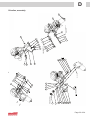
1
- a patient lifter from TM15101 Table of Contents General advice ....................................................... 3 Appendix A ............................................................ 16 Main parts ........................................................17 Explanation of symbols................................... 3 Caution .............................................................. 3 Responsibility ................................................... 3 Appendix B............................................................ 18 Technical description ......................................... 4 Drum assembly .............................................. 21 Chassis ............................................................. 4 Handle ........................................................... 4 Lifting belt with drum ..................................... 4 Motor ............................................................ 4 Brake ............................................................. 4 Electronics..................................................... 4 Battery ........................................................... 4 Hand control unit ............................................. 4 Charger and battery ........................................ 4 Trolley and rail system .................................... 4 Technical data ........................................................ 5 Service ...................................................................... 6 Service lamp .................................................... 6 Service light codes ........................................ 6 Service .......................................................... 6 Molift Service tool ............................................ 6 Troubleshooting ............................................... 6 Cleaning instructions....................................... 6 Inspection Diagram after Service and Repair ........................................................................ 7 Replacing of parts ................................................ 8 Opening the chassis ....................................... 8 Replacing the lifting belt ................................. 8 Replacing the battery ...................................... 9 Replacing of the main circuit board .............. 9 Removing frame assembly .......................... 10 Replacing the solenoid ..................................11 Adjusting and lubrication of brake ................11 Emergency stop switch................................. 13 Labelling ......................................................... 14 Notes: .............................................................. 14 Finishing the job ................................................. 15 Logging ........................................................... 15 Safety control ................................................. 15 Page 2 of 24 Main assembly, front housing ...................... 19 Appendix C............................................................ 20 Appendix D............................................................ 22 Driveline, assembly ....................................... 23 Appendix E ............................................................ 24 Housing, front side ........................................ 25 Housing, back side ........................................ 25 Electrical diagram .............................................. 26 IMPORTANT! The patient lifter is only meant to be used by qualified personnel. The manual shall not be handed over, or made available to, any unauthorised third party, without a prior written consent from Molift Group AS. Existing laws, conventions and agreements protects all documents. No extract of this documentation can be reproduced, used or transferred without prior written consent from Molift Group AS. Violation of these regulations may lead to judicial repercussions and economic responsibility. Industrial rights are reserved. Molift Group AS Ole Deviksvei 44 0668 OSLO, Norway Teleph:(+47) 40001004 Fax: (+47) 40001008 www.molift.com [email protected] TM15101 English - Molift Nomad - Rev. G/ 09/2010 General advice This technical manual contains important safety instructions and information regarding the repair and maintenance of the lifter. Carefully read the manual before working on the lifter in order to be familiar in the function and use of the lifter. Explanation of symbols This symbol is used to point out instructions and information related to work place safety where injury may occur if the information is disregarded or ignored. Follow these instructions, be careful and attentive at all times. This symbol indicates important information regarding the use of the equipment. If not taken into consideration, it may lead to damage or functional defects to the lifter or other equipment. This symbol indicates important and useful information. If taken into consideration, it will help the operator of the lifter to work efficiently. It may help simplify routines and to explain complicated facts. Responsibility Please read these operating instructions care-fully before putting the product into operation. We assume no liability for damage or malfunctions resulting from failure to comply with the instructions. Warranty claims must be made immediately on detecting the defect. Remember to quote the serial number. Consumable parts are not subject to the warranty. All technical information, data and instructions for operation contained in these operating instructions were up-to-date at time of print and are compiled on the basis of our experience and to the best of our knowledge. We reserve the right to incorporate technical modifications within the scope of further development of the product described in this manual. No claims can be derived from the information, illustrations or descriptions contained in these instructions. We assume no liability for any damage or malfunction caused by operating errors, non-compliance with these operating instructions or inappropriate maintenance. We expressly point out that only genuine Molift Group AS spare parts and accessories approved by us may be used. For safety reasons, the fitting and use of spare parts or accessories, which have not been approved, and unauthorised modification or conversion of the product, are not permitted. Molift Group AS will accept no liability for damages resulting from such acts. Caution When repairing the lifter, you will find it necessary to open the lifer. Take care of loose parts, especially screws and washers. When disassembling and assembling the lifter, take care that no cables are With the exclusion of product liability, Molift Group squeezed or damaged, and causing malfunction AS is liable for faults or omissions on its part within the scope of the warranty obligations stated in of lifter. the purchase contract. Claims for damages are Therefore, use general caution when performing excluded, irrespective of the legal reason from which such claims are derived. Only documenmaintenance and repairs. tation belonging to the actual equipment is valid. Read the user manual or operating instrucAny failure to comply with the safety regulations and safety precautions. tions and precautionary measures stated in these operating instructions renders the declaration of conformity supplied with the system in accordance with Council Directive (93/42/EEC) concerning medical devices invalid. Page 3 of 24 Technical description Chassis The chassis consist of two symmetrical plastic covers A 1 , A 2 with operating buttons, lifting belt and lifting handle. Motor, lifting belt wit belt drum, brake, battery and electronics are placed inside the chassis. Handle The handle is mounted in a way to make them a part of the carrying system B 2 of the chassis. The handle with brackets are made of aluminium. Lifting belt with drum The lifting belt C 11 with drum are mounted inside the chassis. The lifting belt goes on or off the drum depending on if the lifter moves up or down. Special leading sleeves are made to avoid damage on the lifting belt and to ensure correct placing on the drum C 1 . Approximity switches D 10 controls the tightness of the belt, and will stop the lifter if the belt gets untight to prevent it from curling. Electronics The electronics consists of a main circuit board E 14 , a DIN-board for the hand control contact E 13 , emergency stop E 7 , emergency lowering E 6 , battery lamp and service lamp. All the functions are dependent on the main circuit board, except the emergency lowering function. On the main circuit board there is a counter which register the number of hours with activity. After a certain time the counter gives a signal to the service lamp that illuminates to show the operator that service is needed. An emergency lowering button is hidden behind the yellow sealing E 11 beside the emergency stop button. Break the sealing and press the emergency lowering button. Battery The battery B 4 is mounted inside the chassis and consists of 20 battery cells in one pack. Hand control unit The hand control unit A 7 has 2 buttons for operating the lifter, one ”up” and one ”down” button, and a lamp indicating when the battery needs charging. The hand control/charging Motor Motor with gear B 2 is mounted inside the chassis. contact is placed on the right on the back side of The force is transmitted via the gear from the the lifter. motor to the drum where the lifting belt is running Charger and battery on or off. Molift NOMAD has a battery which consists of a 26 14 The main circuit board E has an overload V battery pack B 4 , and a charger A 6 which makes protection that cuts the power if the load is too it possible to charge the batteries by placing the heavy. The power will be cut off at 17 A up and 13 hand control unit in the charger. A down. This means that the motor stops working if the load is more than Safe Working Load (SWL). Trolley and rail system Molift NOMAD is attached to a trolley mounted in The emergency stop button E 7 cuts the power the rail system fixed in the ceiling. The rail system supply to the motor and is placed on the front side with trolley is only to be mounted by authorised of the lifter. The emergency stop is activated by personnel, and is described in a separate manual. pressing the button, and deactivated by turning it clockwise until it is released to original position. The lifter shall only be mounted on a rail system with the same lifting capacity or SWL Brake as the lifter or higher. A spring brake is mounted on the cogwheel to the motor. The force from the spring activates the brake in normal position. The brake is deactivated by a solenoid which receives a signal when the motor is running the lifter up or down. The brake prevent the lifter from moving (sag) with static load. Page 4 of 24 TM15101 English - Molift Nomad - Rev. G/ 09/2010 Technical data Material: Fiberarmoured plastic and aluminium. Motor: 24 V DC Battery: 26.4 V NiMH 2.2 Ah Lifting capacity: max 255 kg/562 lbs (SWL) can be adjusted down to 230 kg, 205 kg or 160 kg Lifting height: 2000 mm Lifting speed: 30-35 mm/sec for a normal lift and fully charged battery. Dimensions: 522x200x330 (LxBxH) Weight: 6.8 kg (15 lbs) Technical specifications may change without prior notice. Page 5 of 24 Service Service lamp On the front right side of the lifter there is a service light which will give a signal when the lifter needs service. When there is a green light, the lifter can be used normally. If there is no light, push one of the up/down buttons to activate the electronics, and the service lamp will illuminate. Service Service is to be performed when the service lamp gives a signal or latest after 5 years of use. • Changing of lifting belt with hook • Changing of worn and damaged parts Molift Service tool To be able to read out the data from the lifter, and to reset the service lamp, it is necessary to use the Molift Service tool. See the manual that comes with the Service tool. Install the Molift Service tool on your computer. Connect the lifter to the computer with the cable to the hand control contact. Start the Molift Service tool Software. On the left side in the program menu you can find the lifters data. Service light The electronics measures the operating time of the lifter, and after a specific time the yellow light will illuminate, indicating that the lifter needs service. Take contact with your local Molift service representative/dealer. The lifter can still be operated, but after a while an audible alarm will sound, to remind the operator that the lifter needs service immediately. Service light codes Service light No light Green Yellow Red Red + sound Flashing yellow Mode Power saving Ready for use Book service Perform service Perform service immediately Overheating The electrical system has a power save function which will turn off the electrical system after ten minutes without activity. All lights will turn off. The system is activated when pushing one of the operating buttons. Page 6 of 24 Troubleshooting See the Troubleshooting table in the User Manual. If the troubleshooting procedure does not lead to any diagnosis, judgement and eliminating methods must be used. Cleaning instructions The surfaces of the lifter can be cleaned with a damp cloth using an appropriate detergent. Detergents must be pH-neutral. Do not use solvents or strong liquids - this may damage the surface of the lifter. For disinfection when needed; use isopropyl alcohol. Avoid abrasive cleaning products. The lifter is splash proof, but direct spraying of the lifter should be avoided. If the lifter should be used in a shower room, use a protective bag on the hand control unit. Do not use the lifter permanently in a shower room, as this can cause corrosion inside the lifter. Use in shower rooms requires extra protection, cleaning and maintenance. TM15101 English - Molift Nomad - Rev. G/ 09/2010 Inspection Diagram after Service and Repair Molift Nomad: Check the lifter visually for any damage, faults or deformations, check that the plastic housing has no cracks or any other damages. Check that the lifting belt is not torn, cut, frayed or any other damage. Check that the cables and plug for hand control and charger have no damages. Damaged parts must be changed. Clean plug and socket for hand control with alcohol to remove grease and prevent future contact problems. Check all slings and loops - particularly seems - belonging to this lift. Torn, frayed or cut slings must be replaced. Check that the installation/rail system is marked correctly with SWL (Safe Working Load). Test output of the charger with a voltmeter. Output level is printed on the charger. Chargers with lower output must be changed to provide optimal charging of the batteries. Run the lifter fully up and down a couple of times with and without load to check that the lifter works properly and without irregular noise. Check that the end stop is working. Check that the brake i working with max. load. Mark the lifter with the safety label inscribed with month/year and certificate number for performed safety control. The service technician shall sign the label and this diagram. Service: Check the Service lamp, it gives signal when the lifter needs service. Read the lifters data with the Molift Servicetool and check number of lifts. Service 1 is after maximum 5000 lifts and service 2 after maximum 10 000 lifts. Number of lifts (Sum):_________________________ Service: __________________________________ Service performed: - Change the lifting belt and hook. Check the motor, cogwheel, frame and cables for any damage. Change worn and damaged parts. After service and/or maintenance the service lamp must be reset by using the Molift Servicetool Perform safety control after service/maintenance. NOTE! Reset the service lamp only when service is performed! Safety control and service shall only be performend by partners and/or personnel certified by, or on behalf of Molift Group AS. Always fill out below: Customer:___________________________ Serialnumber lifter:___________________________ Date : ______________________________ Signature :_________________________________ Page 7 of 24 Replacing of parts Replacing the lifting belt Push the emergency stop before performing maintenance on the lifter, to make sure the lifter does not move unintentionally. Opening the chassis • Place the lifter on the table with the backside (with no buttons) against yourself. Unscrew the cap nuts on the backside while holding the screws on the front side in place. When changing the lifting belt it has to be run out completely before the lifter is opened. • Open the lifter as described above. The screw and bolt holding the lifting belt must be on the right side to ensure the best possible availability. • Loosen the microswitch enough to prevent it from stopping the the belt when running it out. • Remove the screw locking the bolt for the belt. Screw Bolt Lifting belt Do not remove the 6 screws in the middle since they keep the washers from falling into the lifter! • Remove the 4 scews closest the lifting hooks (2 on each side). • Lay the lifter carefully down on the table with the front side down. Lift the back cover carefully. • Place a M6 screw in the bolt and remove the bolt. • The lifting belt is now loose and can be removed completely by pulling it out. • Thread the new lifting belt in between the guides. Observe how the cables are placed inside the • Fix the belt with the bolt and the lock screw. lifter. • Run the lifing belt slightly in. Fix the microswitch. When changing the lifting belt, always change the hook too. • Check that the belt moves in and out correctly. • Close the lifter as described in previous chapter. Make sure that no cables are squeezed when replacing the back cover! • Mounting is done in the reverse order. Make sure that no cables are squeezed when replacing the back cover! Page 8 of 24 TM15101 English - Molift Nomad - Rev. G/ 09/2010 Replacing the battery • Open the chassis. Observe how the cables are placed inside the lifter before disconnecting. • Disconnect the battery cable connector (red and black cable) from main circuit board. • Lift the main circuit board enouch to disconnect the cable for temperature sensor. • Pull the battery straight out. • Assembly is done in reverse order. Make sure that no cables are squeezed between the battery and the ribs/walls of the chassis. • Fix the cables with cable strips. Replacing of the main circuit board The circuit board can be changed when all settings and data for this lifter is copied from the old circuit board to the new. If there is any trouble when copying the settings, please send the lifter to Molift Group AS or your dealer. Observe how the cables are placed inside the lifter before disconnecting. • Use the Molift Servicetool , connect to lifter and copy from the lifter to the PC first. Then connect to the new main circuit board and copy on request. • Open the chassis and remove the battery. • Pull the circuit board carefully out and loosen the six cable connectors. • When mounting a new main circuit board, connect the cables in the following order: 1 Emergency lowering cable 2 Temperature sensor cable 3 Cable to brake (motor 2) 4 Cable for switch up/down buttons. Push the diodes and fuses on the new board carefully aside to prevent it from colliding with ribs/walls on the chassis. Microswitches Up/down buttons Brake Emergency lowering Temp.sensor Motor 1 (Liftingmotor) Page 9 of 24 • Put the main circuit board in place. Push it down against the supporting ribs in chassis. Solenoid Make sure that no cables are squeezed. • Place the battery and connect the two remaining cable connectors: 5 Motor cable (motor 1) 6 Battery cable. • The cables must be tied up and fastened to make sure they are not squeezed while mounting the cover. Motor • Place the frame assembly into the housing. Make sure that the bolts are entering correctly. • IMPORTANT! All wires must be placed between the frame and screw, see picture below. The LED on the main circuit board will not illuminate when connecting the battery. There will be a sund (beep) to confirm that the connection is correct. • Close the lifter. • Test the lifter according to safety control check list. Removing frame assembly • When battery, main circuit board and lifting belt are removed, the frame assembly can be lifted out of the cover. It is recommended to use a mounting jig to keep the bolts with washers in place. • Remove the distance (B6) and O-ring (B9) from the screw beside the motoren. • Lift the complete frame carefully out of the housing and place it on a working table. Page 10 of 24 • Put the O-ring (B6) and distance (B9) on the screw besides the motor as shown on the picture below. • Mount the main circuit board, battery and lifting belt. Check that the lifter is working, and close the lifter. Test according to Inspection Diagram. TM15101 English - Molift Nomad - Rev. G/ 09/2010 Replacing the solenoid • Open the lifter, remove the battery and main circuit board. • Lift out the frame assembly. Use a mounting jig to keep the bolts in place. • The complete solenoid (D27) is loosened with a tong since it is secured with Loctite. Hold on the back on the widest part of the solenoid. • Loosen the wire to the solenoid from the main circuit card. • Use a new wire set when mounting a new solenoid. See Appendix F, Electrical diagram. Cut the solenoid PCB wite 15 cm long. • Solder the wire with the solenoid and use thermo shrinking tube. • Mount the solenoid on the frame. Note! Add Loctite 243 on the threads. • IMPORTANT! Make sure that the wires points towards the motor as shown on the picture below. • • • • • • Adjusting and lubrication of brake • Open the lifter, remove battery, main circuit board and lifting belt. • Lift the frame assembly out and place on a working table. • Loosen the screw and washer holding the torsion spring, and remove the spring. • Add grease (SHC007) on the brake disk, and then assemble the torsion spring and brake disk (check spring if necessary). Add grease (SHC007) on the inside surface of the spring. • Mount the brake disk with torsion spring on the motor axle as shown on the picture below. Check position of both ends of spring before pressing the unit onto the axle. Watch the key on axle. Mount the frame assebly in the housing. Mount the main cicuit board and battery. Mount the lifting belt. Check that the lifter is working. Mount the housing and close the lifter. Test the lifter according to Inspection Diagram on page 7. • Mount shims as shown on the picture (B22, 23), use screw (B24). Do not tighten. Page 11 of 24 • Make sure that the end of the spring is between the screws and the two shims. Give the end of the spring a little bend as shown in the drawing below. It is the 5 mm distance to the solenoid that decides where the end of the spring will come. • Before you tighten anything, make sure that the end of the spring is in line with the centre of the solenoid (sideways). Note! If not, the bracket for the solenoid needs to be bended/ adjusted by using a tong, see picture. Check also that the solenoid does not touch anything in opposite housing. If the bracket is bend too much it can come in conflict with the housing. Measure as shown on picture, 44 mm from hole to inside solenoid. • End of spring must be in line with center of solenoid. Check that the spring returns to the same position after activating, ond do not start climbing on next coil of the spring. • IMPORTANT! Check spring assembly according to drawing below. • If te solenoid and the straisht part of the spring are not parallell, the bracket can be adjusted by bending it with a tong • Tighten the two screws (B24). Mu st par be wit ale ll to hin 6 Important! Spring must not go further in than paralell compare to solenoid. Important that spring and solenoid meets in centre of solenoid in about half stroke of solenoid. 5 15 30° R5 Disance between solenoid and spring end = 4 to 5 millimetres when no load on motor. 6° Important that solenoid moves easely when actuating the spring. Pinch it with a finger if any resistant or bending of pin, re adjust spring. Note! If brake must be re adjustet, turn the clamping plates upsdie down or replace to be sure the spring is not seated back into old grove. If possible and space: Make a short bend in the end of the spring to help stabilizing the spring and make the surface for clmping bigger. Designed/Drawn: Date: Projection: Scale: 1:1 xx/xx-xxxx TM15101xx English - Molift Nomad - Rev. G/ 09/2010 Page 12 of 24 Drawing name: Rev. Description: Date/Sign. Approved: Drivline assembly xx xxx Drawing number: Size 14-004_bremsjusteringA3 • Make sure that the spring has been adjusted and assembled according to drawing and instructions above. • IMPORTANT! Run the motor a few rounds by adding electrical power to it. Do this to make the spring “seated”. Add grease on spring. • When the brake is OK, fasten the screw and washer. Remember Loctite 243 on the screw. • Mount the frame assembly back in housing. • Mount the main circuit board and battery. • Mount the lifting belt. • Check that the lifter is working. • Mount the housing and close the lifter. • Test the lifter according to Inspection Diagram on page 7. Emergency stop switch • Open the lifter, remove the battery and main circuit board. • Remove the extension. • Check that the spring holds by using a tong, see picture below. It is important to check tha the distance still is 4 to 5 mm. If not, the end of the spring must be adjusted by bending it to correct distance. See figure above. The holding force is maximum about 6 kg. • Unscrew the black nut on inside and remove the emergency stop button on outside. • Unscrew the black nut on the new emergency stop switch. • Mount the emergency stop switch together with the protecting cover. Put the two parts together into the hole in the cover. Note! Make sure the small knob fits into the slot in the hole. • Use Loctite 243 on the threads and tighten the nut on inside carefully by hand. Note! Make sure that the cam is on upper side. Page 13 of 24 • • • • • • Mount the extension by pressing it down. Mount the main circuit board and battery. Mount the lifting belt. Check that the lifter is working. Mount the housing and close the lifter. Test the lifter according to Inspection Diagram on page 7. Notes: Labelling Check the labels - damaged labels are to be replaced. Page 14 of 24 TM15101 English - Molift Nomad - Rev. G/ 09/2010 Finishing the job Logging The service manual has a table for logging of repair and work done on the lifter. Write down a short description of the incident in the appropriate interval. This will enable the owner and service partner to see previous history for the lifter and in that way maybe making future fault finding and repairs easier. Safety control Any repair or replacement of parts requires a safety control afterwards as described in the procedures for service, maintenance and safety control. Date Description of fault Type of repair Date/sign. Page 15 of 24 Appendix A Pos. Fig/Part. no Qty. Description 1 Appendix B 1 Front housing with interior parts 2 Appendix E 1 Back housing assembly 3 1220333 10 Cap nut M6 TP RAMPA 99-025-61-301 4 1100303 1 Decal, security control 5 1100306 1 Decal, calendar 6 1240001 1 Charger, Nomad 7 2017002 1 Hand control, Nomad Page 16 of 24 TM15101 English - Molift Nomad - Rev. G/ 09/2010 A Main parts C probe 1 Mounting height probes 1,2 (4X) probe 10 8 13 SECTION probe-probe SCALE 1 : 2 2 7 Apply LOCTITE 243 on 5 bolts. (Bolts secure the frame) 9 B 4 5 6 Temp 1 Charger 2 (-) 11 7Charger 1 (-) 6 Temperature 1 Temp 2 146,6 Charger 1 (+) E Procedures: - 14-P01 Assembly instructions - 14-P02 Control scheme B 5 D 1 Pos. 3 4 13 1 Label Charger mode 1 0 1 1 1 4 4 4 4 Mould charger handcontroll LED LEDBOM.xls bracket 14-001 Charger_2215 Dimension/ Rear plate Draw. no.screw Plastic Rubber dampener Probe sleeve Battery probe Qty. 9 8 7 Bill of materials: 6 5 Description. 4 3 2 1 Pos. Qty. Designed/Drawn: Date: Drawing name: A Rev. RVS MHL TÅB Released for production 08.02.2005 RVS 09.02.2005 TÅB Description: Date/Sign. Approved: Material: Comment: Drawing name: 26.03.2008 RVS 11.02.2005 RVS Comment. Scale: Designed/Drawn: Date: Added label Added pos. 11 for label 14-153 LTL-30EHJ-012 RTC 51 2215 spec ed._ 24238B 14-154 Material. PT 1452 40 X 16 Rubber dampener RSS-100-CR GSS-10 Dimension/ Draw. no. Description Projection: C B 14-231 1 Label charger 2,5Nm handcontroll (10x), 14-201 All bolts to1011be tightened with 1 Electric wiring diagram 14-145 09/02-2005 Projection: Scale: B Charger handcontroll assy 1:1 Drawing number: Molift Nomad Size 14-157 Drawing number: Page 17 of 24 Size A2 Appendix B Pos. Part. no. Qty Description 1 App. C 1 Drum assembly 2 App. C 1 Drive line assembly 3 App. D 1 Front cover assembly 4 1221115 1 Battery 26,4 V NiMH 5 1220335 1 Spacer Ø10,0/Ø6,3/48 mm PA6 6 1220334 1 Spacer Ø10,0/Ø6,3/61 mm PA6 7 1220303 10 Screw, cylinder DIN 912 8,8 ElZn, M6x80 8 1220160 10 Bushing Ø6, 3xØ8x11 9 1220340 6 O-ring 5,3x2,4 Nomad 10 1220124 1 Belt Guidance Nomad Page 18 of 24 TM15101 English - Molift Nomad - Rev. G/ 09/2010 B Main assembly, front housing E 10 7 8 9 9 6 7 8 9 4 F 3 9 F 9 Note! O-rings are used to keep the bolts in 2 9 G 5 1 Pos. G Added pos no for el scheme 01.09.2008 TÅB MHL F Pos 4 and 9 Changed item no. 11.08.2008 TÅB MHL Pos 10 New belt guidance 04.04.2008 TÅB Uppdate, rubber washer taken away 20.06.2007TÅB MHL MHL E D C B A Rev. Pos 10 Changed quantity Pos 9 and 10 changed Released for production Description: 06.11.2006 TÅB 11.08.2006 TÅB 21.02.2005 TÅB Date/Sign. MHL MHL ORH Approved: Cabel layout see dwg 14 11 1 Bill of materials: Qty. Description. Designed/Drawn: Date: TAB Drawing name: 21/02-2005 14-002 BOM.xls Dimension/ Draw. no. Projection: Scale: Front housing w. interior parts Complete lift motor MOLIFT NOMAD Page 19 of 24 1:2.5 Appendix C Pos. Part. no. Qty Description 1 1220150 1 Drum 2 1220180 1 Gear wheel M1,75 Z=58 3 1220151 1 Hollow axle for drum 4 1220103 1 Emergency brake, Nomad 5 1220154 1 Locking bolt for lifting belt 6 1220191 1 Torsion spring R=0,25 NMM/GRAD, Nomad 7 1220152 1 Bolt for emergency brake 8 1220337 1 Screw NF M6x10 Rampa part no 151-610-001 9 1220312 2 Circlip DIN 6799 10 1220341 1 Machine screw M3x120 DIN 7985A 11 1220195 1 Lifting belt complete Page 20 of 24 TM15101 English - Molift Nomad - Rev. G/ 09/2010 C Drum assembly Apply Grease MOBILITH SHC007 during assembly D 11 9 4 9 5 3 2 *=A 10 Pos. 1 Q 6 7 Designed/D 8 D C B A Rev. Lifting belt new item no. Re numbered pos no. Pos 11 changed to screw M4 not self tapping Pos 9-11 changed Released for production Description: TE/TA 02.11.2006 TÅB MHL 11.08.2006 TAB RVS 27.10.2005 TÅB 14.02.2005 TAB Date/Sign. RVR ORH Approved: Page 21 of 24 Drawing na Drum Front MOLIF Appendix D Pos. Part. no. Qty Description 1 1220101 1 Frame assembly 2 1220181 1 Gear assembly 3 1220155 2 Axle for guiding drum 4 1220157 1 End registration drum 5 1220162 1 Axle for gears 6 1220158 1 Guiding drum 7 1220163 1 Registrator for drum diameter 8 1220102 1 Rotation stopper for axle 9 1220308 2 Screw M6x20 ISO 7380 4.8 Elzn hex.socket 10 1220116 3 Microswitch Omron 11 0310120 2 Washer Ø4 DIN 9021 Elzn 12 1220305 2 Washer Ø6 DIN 125 Elzn 13 1220192 1 Extension spring SS2331-06 14 1101433 3 Spacer Ø5,2xØ10x5 15 1220141 4 Thrustwasher I Glidur G 16 1220339 3 Pop rivet Ø4x16 DIN 7337 17 1101532 2 Screw M4x8 ISO 7045 buttonhead 18 0540509 4 Washer Ø4, Starlock 19 1220313 2 Circlip Ø6 RS DIN 6799 20 1220110 1 Motor Valeo 21 1220140 2 Flange bearing Ø10/Ø12-10 22 1220105 1 Shims 23 1220104 1 Shims 24 1220320 2 Screw M6x16 DIN 912 Elzn cap head 26 1220318 1 Screw M6x16 DIN 7991 Elzn countersunk 27 1220501 1 Solenoid complete 28 1220193 1 Torsion spring 29 1220311 6 Pop rivet DIN 7337 Ø2,5x12 Al 30 1220159 1 Gear wheel with brake disk 31 1220194 2 Extension spring SS2331-06 25 Page 22 of 24 TM15101 English - Molift Nomad - Rev. G/ 09/2010 21 2 21 12 9 23 ? 22 24 30 28 Apply Grease on the disk before mounting the spring. F J 31 27 26 16 10 G 9 Apply LOCTITE 243 when mounting solenoid 14 12 29 3 1 10 29 14 31 16 J Key follows motor 3 J 10 18 18 29 11 17 17 8 5 I H 14 19 15 3 Apply oil Wurth HHS2000 During assembly 16 15 13 6 11 19 18 15 7 15 3 18 24.04.2008 TÅB 29.08.2007TÅB Changed item no pos 17 Added dwg no at pos 27 Added LOCTITE 234 for solenoid G F E 27.06.2005 TAB Uppdated drawing with brake parts Adjusted pos no Released for production Description: D C B A Rev. 24.02.2005 TAB 21.02.2005 TAB Date/Sign. 13.05.2005 TAB 01.08.2006 TAB Uppdate of drawing Uppdated after mounting of first series. 11.08.2008 TÅB Pos17: Was 1, Pos25: Replaced by pos17, Pos 30: New art.no. 19.08.2008 TES 24.09.2008 TES I Pos 13: Reduced qty. from 3 to 1. Pos 31 added 30 H J Apply oil Wurth HHS2000 During assembly 4 270,1 ORH ORH Approved: MHL IVS MHL TS MHL MHL MHL MHL 20 252 1 Bill of materials: Qty. Description. 1:2 14-004 BOM.xls Dimension/ Draw. no. 21/05-2005 Projection: Scale: Drivline assembly Front housing w. interior parts MOLIFT NOMAD Drawing name: TE / TAB Designed/Drawn: Date: Pos. Material. Note! Brake to bes tested and adjusted. Set voltage on t that the solenoid is capable of releasing the brak Ensure that the spring is clamped and is not slipp Driveline, assembly Drawing nu D Page 23 of 24 Appendix E Pos. Part. no. Qty Description 1 1220120 1 Housing 2 1220121 1 Hook, right side 3 1220122 1 Hool, left side 4 1220125 1 Foil, front side 5 1220114 2 Switch, black, ELFA 35-525-02 6 1220118 1 Switch, red, ELFA 35-525-02 emergency lowering 7 0920114 1 Emergency stop button, EFA Elektro 8 1220330 6 Screw, TP, WN1451, K40x22 ElZn 9 1220331 2 Screw, TP, WN1451, K30x10 ElZn 10 1220142 1 Distancer/extension emergency stop button 11 0210307 1 Label Ø30 emergency lowering 12 1220123 1 Cover for emergency stop button 13 1220128 1 LED-DIN PCB 14 1220112 1 PCB main circuit board 1 1220120 1 Housing 2 1220121 1 Hook, right side 3 1220122 1 Hool, left side 4 1220126 1 Foil, back side 5 1220330 6 Screw TP WM1451 K40x22 Page 24 of 24 TM15101 English - Molift Nomad - Rev. G/ 09/2010 E Housing, front side Add LOCTITE 243 7 D 10 C 12 14 1 E 13 6 9 11 8 3 5 4 2 Housing, back side 5 1 C 318,5 5 Housing modiications 04.04.2008 MHL B New main PCB, new DIN-LED card. Added cover for emergency sw. 27.04.2006 JFS TBN A Released for production 18.02.2005 TAB ORH C Innført pos 12 med delenr 24.10.2006 TÅB MHL D Changed part no pos 10. Was 03174. 02.03.2007 TÅB RVS Description: Date/Sign. Rev. 3 2 4 102 E Page 25 of 24 Approv TM15101 English - Molift Nomad - Rev. G/ 09/2010 16 leader cable From DIN /LED to main PCB Motor cable Red Solenoid Gray Emergency lowering Gray Purple Yellow Blue Not in use Green Not in use Orange Red Brown Power from battery Red / Black 5 Sensor Cable Sensor cabel from battery Black Not ion use White Not in use Cable 4 4 Emty Drum 1 2 4 LED BATTERY 10 Black P5 1 End Up 2 Cable 3 B MOTOR 2 Ref dwg 14-002 P1 1 Bill of materials: 03.08.2006 Projection: Scale: Dimension/ Draw. no. 1:5 14-191 BOM.xls 7 + Purple Black 13.10.2008 RVS 14-191 Drawing number: Material. Changed pos. 1. Electrical diagram w cable layout Complete lift motor MOLIFT NOMAD Drawing name: TBN Qty. Description. 1 MOT Designed/Drawn: Date: Pos. 6 8 Cable 2 P4 BATTERY P1 + - NC 16 1 3 1 2 3 Red 5 1 13-P DIN P2 Brake /solenoid Cabel 5 2 4 1 Connection Handcontr oller dwg. 14-109 4 P9 1 LED-DIN card DWG 14-187 Main card DWG 14-188 EMG. down MOTOR 1 6 1 P6 1 2 Page 26 of 24 13-P DIN D MHL Comment. Electrical diagram A2 Size F Sensors Page 27 of 24 Norway Germany New Zealand Molift AS Ole Deviksvei 44 0668 OSLO Tlf: (+47) 40001004 Fax: (+47) 40001008 www.molift.com Thomashilfen für Behinderte GmbH & Co Walkmühlenstrasse 1 27432 Bremervörde Tel.: 0 47 61 / 88 60 Fax: 0 47 61 / 886 19 www.thomashilfen.de Herrmann & Co GmbH Oelder str. 20 33378 Rheda-Wiedenbrück Tel: 05242 / 9671 40 Fax: 05242 / 9671 41 www.herrmann-co.de Morton & Perry Homecare Equipment P.O. Box 34439 Birkenhead Auckland 0746 www.mortonperry.co.nz Australia Patient Handling Australia 8 Chapel Street Marrickville NSW 2204 Sydney www.patienthandling.com.au Ceiling Hoist Solutions Melbourne Office 58-62 Star Crescent AU-3803 Hallam, VIC www.ceilinghoistsolutions.com.au Austria Paul Bständig GesmbH Strohbogasse 8 1210 Wien Tel. 01-405 35 43 Fax 01-406 81 02 www.bstaendig.at Belgium Pronk ergo NV Sint-Pietersmolenstraat 204/1 8000 Brugge T +32 (0)50/32 20 20 F +32 (0)50/32 20 40 www.pronkergo.be Danmark Handicare A/S Jernholmen 41 2650 Hvidovre Tel. +45 70 22 43 41 www.handicare.dk Finland Mediq Suomi Oy Orionintie 5/ P.O.Box 8 FI-02101 Espoo Tel.: +358 10 429 99 Fax: +358 10 429 2047 www.mediq.fi Iceland Eirberg Storhofoi 25 IS-110 Reykjavik www.eirberg.is Ireland Meditec Medical Ltd. Unit 28, Whitestown Drive Whitestown Industrial Estate Tallaght, Dublin 24 Tel: 01 4624045 www.meditecmedical.ie Israel Mediscan Systems Ltd P.B Box 2195 6 Hamanov St. Rehovot 76386 IL-76121 Rehovot www.mediscan.co.il Italy Fumagalli Piazza Puecher 2 22037 Pontelambro Tel +39 031 3356811 Fax +39 031 622111 www.fumagalli.org Japan Pacific Supply Co. Ltd 1-12-1 Goryo, Daito-shi JP-5740064 www.p-supply.co.jp France Netherlands Praxis Medical Technologies Parc 2000 107, rue Dassin 34080 Montpellier FRANCE Phone +(33) 04 99 77 23 23 Fax +(33) 04 99 77 23 39 [email protected] Pronk Ergo bv Cobaltstraat 14 2718 RM Zoetermeer Tlf: 079-361 13 40 Fax: 079-361 13 41 www.pronkergo.nl Spain Karinter S.L C/Ramón Turró, 5-9 Local 4 08005 Barcelona Tel. +34 93 221 19 17 Fax. +34 93 221 18 72 www.karinter.com Sverige Molift AB Ekbacksvägen 26 168 69 Bromma Tel: 08-564 616 50 Fax: 08-564616 59 www.molift.com Switzerland Kuhn und Bieri AG Könizstrasse 227 3097 Bern - Liebefeld Tel. 0848 10 20 40 Fax 031 970 01 71 www.kuhnbieri.ch United Kingdom Meditec Molift Ltd Hi Trac House Unit 1 Woodrow Business Centre Woodrow Way, Irlam Manchester M44 6NN Tel. 0844 8004236 Fax 0844 8004237 www.molift.com USA Molift Inc. 8406 Benjamin Road Suite C Tampa, FL 33634 Tel. 813-969-2213 Fax 813-969-3954 www.moliftinc.com