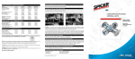
1
Spicer Driveshafts
®
Service Manual
Spicer ® Life Series
DSSM-0100
April 2015
Table of Contents
Inspection Procedures
Inspection Warnings and Cautions . . . . . . . . . . . . . . . . . .1
Universal Joints . . . . . . . . . . . . . . . . . . . . . . . . . . . . . . . . .4
Slip Member Assembly . . . . . . . . . . . . . . . . . . . . . . . . . . .5
Tubing Inspection . . . . . . . . . . . . . . . . . . . . . . . . . . . . . . .7
Center Bearings . . . . . . . . . . . . . . . . . . . . . . . . . . . . . . . . .7
Lubrication
Warnings and Cautions . . . . . . . . . . . . . . . . . . . . . . . . . . .8
Recommended Lubricants for Relubable Universal Joints and
Slip Members . . . . . . . . . . . . . . . . . . . . . . . . . . . . . . . . . .9
Grease Compatibility . . . . . . . . . . . . . . . . . . . . . . . . . . . . .9
Universal Joints . . . . . . . . . . . . . . . . . . . . . . . . . . . . . . . .10
Slip Joint . . . . . . . . . . . . . . . . . . . . . . . . . . . . . . . . . . . . .12
Center Bearings . . . . . . . . . . . . . . . . . . . . . . . . . . . . . . . .13
Removal
Warnings and Cautions . . . . . . . . . . . . . . . . . . . . . . . . . .14
Driveshaft Assemblies . . . . . . . . . . . . . . . . . . . . . . . . . . .15
Grease Zerk Removal and Installation . . . . . . . . . . . . . . .16
Slip Member Boot . . . . . . . . . . . . . . . . . . . . . . . . . . . . . .18
Center Bearing . . . . . . . . . . . . . . . . . . . . . . . . . . . . . . . . .19
Installation
Warnings and Cautions . . . . . . . . . . . . . . . . . . . . . . . . . .21
Universal Joint - Snap-Ring Style. . . . . . . . . . . . . . . . . . .22
Universal Joint - Spring Tab Style . . . . . . . . . . . . . . . . . .24
Center Bearing . . . . . . . . . . . . . . . . . . . . . . . . . . . . . . . . .25
Slip Member and Boot . . . . . . . . . . . . . . . . . . . . . . . . . . .26
Driveshaft . . . . . . . . . . . . . . . . . . . . . . . . . . . . . . . . . . . .27
Glossary
Glossary . . . . . . . . . . . . . . . . . . . . . . . . . . . . . . . . . . . . . .29
Appendix . . . . . . . . . . . . . . . . . . . . . . . . . . . . . . . . . . . . .32
For additional service information, go to www.dana.com or
call 1-877-777-5360.
i
General Information
Spicer Life Series™ Features and Benefits
Note: Spicer Life Series™ driveshafts are found on vehicles
throughout the world. Therefore, this manual includes
worldwide terminology.
This manual encompasses inspection, lubrication, removal
and installation procedures for Spicer Life Series™ 55, 70, 90,
100, 140, 170 and 250 driveshaft assemblies.
Important Features of a Spicer Life
Series™ Driveshaft
Spicer offers a complete range of driveshaft solutions to meet
the full spectrum of needs in medium and heavy duty applications. The Spicer Life Series™ driveshafts have been designed
and developed to stand up to the wear and tear of heavy hauling tasks. They are the first driveshafts in the industry to be
compatible with advancing powertrain specifications for
higher engine torque and lower axle ratios. No one does more
than Spicer in meeting the needs of the marketplace.
Spicer Life Series™ driveshafts offer:
•
Longer life
•
Lower lifetime management
•
Increased strength for higher engine torque and
lower axle ratios
•
Smaller driveshaft rotating diameter
Spicer Life Series™ award winning* universal joint kits are
specifically designed to give extended driveshaft life. Flatended needle bearings are used to withstand oscillating loads
while the driveshaft is rotating and to eliminate skewing in the
bearing cup. Thrust washers significantly reduce end galling
on trunnion ends and lower universal joint operating temperature. Synthetic rubber seals and plastic seal guards provide
lubricant retention and help prevent the entry of foreign material, significantly increasing universal joint life. The centrally
located grease zerk (nipple) fitting increases the strength of
the journal cross and allows more torque carrying capacity.
High-strength steel tubing is used to provide maximum
torque carrying capacity at minimum practical weight.
Increased tube diameter allows a higher critical speed and
longer one-piece driveshafts. This increased stiffness also
improves noise, vibration and harshness. New slip member
booting or alternative seal can offers better protection against
environmental contaminants, increases component life, and is
lubricated for the life of the product.
The new integral tube sleeve and yoke shaft design, found on
heavy duty Spicer Life Series™ designs, along with larger
diameter involute splines, creates greater strength and torsional stiffness with less weight. This new design leads to
improved balance and less slip effort, resulting in reduced
noise and vibration for the entire driveshaft system. Spicer
Glidecote®, found in all slip member assemblies, reduces
friction, thereby lowering thrust loads under high torque. This
nylon coating also prevents spline wear and extends life.
A driveshaft that transmits high torque loads must be durable
and strong. Spicer uses forged steel and high strength cast
yokes to provide the necessary rigidity to maintain bearing
alignment under torque loads. Spicer Life Series Quick Disconnect™ end yokes reduce the time to remove or install the
driveshaft, equating up to a 75% labor savings for service.
Applications requiring flange connections, S.A.E., DIN and
cross-serrated T-Flanges are available. A new cold-formed,
bearing retainer provides structural rigidity and reduces bearing movement which may result from overloading.
ii
General Information
General Information
Warnings and Cautions
Spicer Life Series™ Inspection Warnings and Cautions
Before You Get Started
1.
ALWAYS wear safety glasses when performing
maintenance or service. Failure to wear safety
glasses can result in personal injury and/or partial or
complete vision loss.
2.
NEVER go under a vehicle while the engine is running. Be sure the vehicle's engine is off, and keys are
removed from ignition.
3.
NEVER go under or work on a vehicle that is not on a
level or flat surface.
4.
NEVER work on a driveshaft without blocking the
vehicle's wheels and releasing all parking brakes.
See warning below.
5.
NEVER lift a vehicle without the appropriate weightrated, vehicle-support equipment.
6.
NEVER REMOVE a driveshaft from the vehicle without keeping the vehicle's transmission in neutral.
See above warning.
7.
CAUTION – Spicer Life Series™ driveshaft assemblies can weigh in excess of 100 pounds (46 kilograms). Be sure to use proper lifting techniques
when handling Spicer Life Series™ driveshafts. More
than one person may be needed when handling
driveshaft assemblies.
8.
ALWAYS use support straps to prevent the driveshaft from falling, causing injury and/or damage during the loosening or removal of any driveshaft
hardware.
9.
NEVER heat components or use sledgehammers or
floor jacks to remove the driveshaft from vehicle.
Note: For driveshaft applications that have pillow blocks,
dampers, parking brakes or retarders, refer to these
component manufacturers' or the original equipment
vehicle manufacturers' service manuals for proper procedures.
WARNING: Reassembly of a driveline out of original phase
can cause vibration and failure of the drivline and attaching
components.
WARNING: Driveshaft assemblies can weigh in excess of 100
pounds(46 kilograms). Be sure to use proper lifting techniques when handling driveshafts. More than one person
may be needed when handling driveshaft assemblies.
WARNING: Never heat components, never use sledge hammers, and never use floor jacks to disassemble driveshafts.
This can result in damaged, weekened, or bent components.
End Fitting
WARNING
WARNING: A loose end-fitting can result in driveline failure,
which can in turn lead to separation of the driveline from the
vehicle. A separated driveline can lead to property damage,
serious personal injury, or death.
Universal Joint
WARNING
WARNING: Excessive looseness across the end of universal
joint bearing cup assemblies can cause imbalance or vibration
in the driveshaft assembly. Imbalance or vibration can cause
component wear, which can result in separation of the drivline.
WARNING: DO NOT reuse bolts or use inferior grade bolts.
Reuse of bolts and/or use of inferior bolts can cause driveline
failure, which can result in separation of the drivline from the
vehicle.
WARNING: Failure to torque bolts to specification can cause
driveline failure, which can result in separation of the driveline
from the vehicle.
Driveline
WARNING
WARNING: Failure to replace damaged driveline components
can cause driveline failure, which can result in separation of
the driveline from the vehicle. A separated driveline can result
in property damage, serious personal injury, or death.
1
CAUTION: Use a journal locator to avoid nicking journal cross
trunnions or damaging oil seal slingers.
CAUTION: If a bearing assembly or journal cross is worn or
damaged, the universal joint assembly must be replaced.
CAUTION: Be sure the snap rings are properly seated in the
snap ring grooves.
Warnings and Cautions
WARNING
WARNING: Excessive radial looseness in the slip member
assembly can cause imbalance or vibration in the driveshaft.
Imbalance or vibration can cause components to wear, which
in turn can result in separation of the driveline from the vehicle. A separated driveline can cause property damage, serious personal injury or death.
Yoke (Includes Slip Yoke, Yoke Shaft, and
Tube Yoke)
WARNING: A loose or damaged slip yoke seal allows contaminants to invade the slip member assembly. Invasion of contaminants into the slip member assembly can degrade the
grease, and damage slip member components, which can
result in driveline separation.
WARNING: DO NOT deform yoke cross holes by removing
excessive metal. Raised metal or deformed yoke cross holes
can be a cause of cross and bearing failure, which can result
in separation of driveline from the vehicle.
WARNING: DO NOT touch or disturb the micro-encapsulated
adhesive found on the midship nut threads. Doing so may initiate the curing process and impair the installation of the nut.
Premature curing of the micro-encapsulated adhesive will
result in improper installation of the midship nut. Improper
instsallation of this nut can cause driveline failure, which can
result in separation of the driveline from the vehicle.
WARNING: Failure to torque the midship nut to required
specifications can cause driveline failure, which can result in
separation of the driveline from the vehicle.
WARNING: A loose midship nut can result in driveline failure,
which can result in separation of the driveline from the vehicle.
Center Bearing
WARNING
WARNING: Loose center bearing bracket bolts can result in
driveline failure, which can result in separation of the driveline
from the vehicle.
WARNING: Yoke shaft assemblies can weigh in excess of 50
pounds (23 kilograms). Be sure to use proper lifting techniques when handling yoke shafts.
WARNING: Damaged center bearings or center bearing components can cause imbalance or vibration in the driveshaft
assembly. Imbalance or vibration can cause component
wear, which can result in separation of the driveline from the
vehicle.
Tubing
Foreign Material
WARNING
WARNING: Bent or dented tubing can cause imbalance or
vibration in the driveshaft assembly. Imbalance or vibration
can cause component wear, which can result in separation of
the driveline from the vehicle.
CAUTION: Do not bend or dent the tube when handling or
servicing driveshaft.
Midship Nut
WARNING
WARNING: DO NOT reuse the midship nut. Reuse of the
midship nut can cause driveline failure, which can result in
separation of the driveline from the vehicle.
WARNING
WARNING: Build-up of foreign material, excessive paint, or
undercoating on a driveshaft can cause imabalnce or vibration
in the driveshft assembly. Imbalance or vibration can cause
component wear, which can result in separation of the driveline from the vehicle.
WARNING: A contaminated slip member can result in separation from the vehicle. A separated driveline can result in property damage, serious personal injury or death.
Hardware
WARNING
WARNING: Loose, missing, or damaged bearing retainers or
stamped straps, retaining bolts, nuts, end fitting tangs, snap
2
Warnings and Cautions
Slip Member
Warnings and Cautions
rings, or rotating bearing cups can result in driveline failure.
A separated driveline can lead to property damage, serious
personal injury, or death.
WARNING: DO NOT reuse bolts, straps, nuts, or damaged
bearing retainers or inferior grade bolts. Reuse of bolts,
straps, nuts, or damaged bearing reatiners, or use of inferior
grade bolts can cause driveline failure.
CAUTION: If loosening or removing bolts, always install a
new strap and bolts and torque bolts to specification.
Lubrication
WARNING
WARNING: A missing, loose, or fractured grease zerk (nipple) fitting or plug eliminates the ability to lubricate the universal joint. Improper or inadequate lubrication can cause
driveline failure, which can result in separation of the driveline
from the vehicle.
WARNING: Improper lubrication techniques can cause driveline failure, which can result in separation of the driveline
from the vehicle.
WARNING: A missing, loose, damaged, or fractured plug or
grease zerk (nipple) fitting can allow contaminants to invade
the universal joint. Invasion of contaminants into the universal joint can degrade grease and cause universal joint damage, which can result in separation of the driveline from the
vehicle.
WARNING: Incompatible greases that are applied to universal
joints and/or slip members can result in driveline failure and
can result in separation of the driveline from the vehicle.
WARNING: Hand tightening of grease zerk (nipple) fitting or
plugs is NOT recommended. Failure to torque grease zerk
(nipple) fittings to specifications can result in separation of
the driveline from the vehicle.
WARNING: Maximum grease gun pressure should not
exceed 60 psi. Excessive grease gun pressures may cause
seal damage.
CAUTION: In cold temperatures, be sure to drive the vehicle
immediately after lubrication. This activates the slip spline
and removes excess grease. Failure to do so could cause
excess grease to stiffen in the cold weather and force the plug
out. The end of the spline would then be open to collect contaminants and cause the spline to wear and/or seize.
3
CAUTION: All slip yoke and universal joint seals should be
completely purged.
Inspection Procedures
Visually inspect all input and output end-fitting retaining nuts
or bolts for any gaps between mating surfaces. If gaps are
present, consult transmission, axle or transfer case original
equipment manufacturers' service and maintenance manuals
for proper fastener specifications.
Visually inspect for damaged bearing retainers or stamped
straps, loose bearing retainer bolts or strap bolts, loose companion flange bolts and nuts, loose or missing spring tabs or
spring tab bolts, damaged tangs on end fittings, damaged or
missing snap rings, and rotating bearing cups.
If any of these situations are evident, replacement of the components is necessary. Refer to the removal and installation
sections of this manual for proper replacement procedures.
Universal Joints
Note: The following procedures are to be performed prior to
any lubrication of universal joints or slip members. The
addition of lubricant can mask the looseness in a componet that is beginning to show wear and may be in
need of replacement.
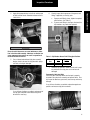
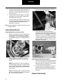
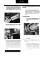
1.
Check for excessive looseness across the ends of
the universal joint bearing cup assemblies and trunnions. Take hold of the inboard yoke on the driveshaft with both hands. Try to move the yoke
vertically and horizontally.
IMPORTANT
Note: If the movement of the driveshaft is greater than .006",
the carrier assemblies input shaft and/or output shaft
ends play must be checked to make sure they are within
specification. Endplay readings that are out of specification must be corrected before an accurate driveshaft
reading can be taken. Refer to the Input/Output Shaft
Endplay Inspection procedure.
WARNING
Excessive looseness across ends of universal joint bearing
cup assemblies can cause imbalance or vibration in the
driveshaft assembly. Imbalance or vibration can cause
component wear, which can result in separation of the driveline from the vehicle.
Check Input Shaft End-Play (Forward Axle)
a.
Position dial indicator at yoke end of input shaft.
b.
Push on input shaft and zero dial indicator.
c.
Using pry bar, move input shaft axially and measure/
record end-play.
There should be less than .006" (.15mm) movement
in the universal joint relative to the inboard or outboard yokes. If looseness is greater than .006"
(.15mm), the universal joint kit may need to be
replaced.
Add shims to increase end-play.
Note: Input and output shaft endplay specifications will vary
between model. Refer to manufacturer’s service manual
for correct endplay specifications.
4
Inspection Procedures
Inspection Procedures
Inspection Procedures
Remove shim to decreased end-play.
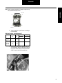
Measured end-play (Step 3)
0.015” – 0.015”
Desired end-play (New Parts)
0.003” to 0.007”
Remove shims to provide desired
end-play
0.012” to 0.008”
Check Output Shaft End-Play (Forward Axle)
a.
Position dial indicator at yoke end of input shaft.
b.
Push on output shaft and zero dial indicator.
c.
Using pry bar, move input shaft axially and measure/
record end-play.
3
-
If grease zerk fitting is loose, tighten to required
specifications.
-
If grease zerk fitting is fractured, replace grease zerk
fitting and tighten to required specifications.
-
If grease zerk fitting is missing, the entire universal
joint kit needs to be replaced.
-
If the plug is loose, tighten to required specifications.
-
If a plug is missing or fractured, the entire universal
joint kit needs to be replaced.
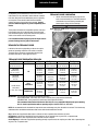
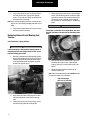
Slip Member Assembly Inspection
1.
Check the slip member assembly for excessive radial
looseness. Using a dial indicator, take hold of the
tubing near the slip member with both hands and try
to move vertically, up and down relative to the
ground.
2.
Arrange dial indicator with magnetic base one-quarter inch (1/4") from the driveshaft’s tube weld. Dial
indicator should be firmly mounted on the tube so
that no movement of the dial indicator base is
allowed.
3.
Extend dial indicator arm from the base, across the
slip member boot, allowing the dial indicator to contact the yoke shaft tube one quarter inch (1/4") off
the opposite side of the boot from where the magnetic base is mounted. Dial indicator’s arm should be
running parallel to the driveshaft.
2
1
Note: The output yoke can be installed when taking end-play
measurements.
d.
Correct end-play for new assembly is .001" to .015".
Grease Zerk Inspection
Check for presence of all grease zerk fittings. Grease zerk fittings should not be loose, fractured or missing.
5
Inspection Procedures
Apply effort perpendicular to shaft axis making note
of total indicator travel. Allowable indicator travel is
.000-.012 in.
6.
Visually inspect for the presence of the grease zerk
fitting, if applicable, on the slip yoke.
a.
If grease zerk fitting is loose, tighten to required
specifications. (See Table C.)
b.
If grease zerk fitting is missing or fractured, the
slip members may need to be replaced.
WARNING
Excessive radial looseness can cause imbalance or vibration in the driveshaft assembly. Imbalance or vibration can
cause component wear, which can result in separation of
the driveline from the vehicle.
5.
For an inboard and outboard slip yoke assembly
design, check to be sure the slip yoke welch plug is
not loose, missing or damaged.
Table C - Slip Member Grease Zerk Fitting Specifications
Thread
Size
Zerk
Nm
Torque
IN. LB.
0.25"-28"
3.5-6.2
31-55
7.
Check the slip yoke seal. Make sure the seal is properly attached to the slip yoke and is not loose or
damaged.
Permanently Lubricated Style
Check the yoke shaft boot. Make sure the boot is properly
attached to the yoke shaft assembly and splined sleeve. Visually inspect for boot tears, punctures, loose clamps and clamp
damage.
If any of these situations are evident, replace damaged components and measure slip joint movement.
If any of these situations are evident, replacement of
the slip yoke and professional rebalancing of the
driveshaft is necessary.
6
Inspection Procedures
4.
Inspection Procedures
Tubing Inspection
1.
Check the driveshaft for bent or dented tubing. If
either of these situations is evident, replacement of
the complete driveshaft assembly or tube is necessary.
2.
Make certain there is no buildup of foreign material
on driveshaft.
If found, buildup should be removed carefully to
avoid damaging the driveshaft.
a.
When removing dirt or mud, rinse with water.
b.
When removing tar or undercoating, use mineral spirits or any appropriate solvent.
Center Bearings Inspection
1.
Visually inspect all center bearings, end-fitting midship nuts for any gaps between the mating surfaces.
Note: Be sure to repeat steps 2 and 3 for all center bearing
end fittings for broken back and backlash.
2.
Inspect the center bearing bracket bolts for looseness.
Note: If looseness is evident, retighten center bearing bracket
bolts. Consult the vehicle manufacturers’ specifications
for proper bolt torque. Check the alignment of the
bracket before tightening the bolts. Bracket should not
be skewed.
3.
7
Visually inspect the center bearing rubber cushion
for damage. Make sure the slingers are not rubbing
against the rubber cushion. Verify that the rubber
cushion is properly seated in the metal bracket.
Lubrication Warnings
Spicer Life Series™ Lubrication Warnings and Cautions
1.
ALWAYS wear safety glasses when performing
maintenance or service. Failure to wear safety
glasses can result in personal injury and/or partial or
complete vision loss.
2.
NEVER go under a vehicle while the engine is running. Be sure the vehicle's engine is off, and keys are
removed from ignition.
3.
NEVER go under or work on a vehicle that is not on a
level or flat surface.
4.
NEVER work on a driveshaft without blocking the
vehicle's wheels and releasing all parking brakes.
See warning below.
5.
NEVER lift a vehicle without the appropriate weightrated, vehicle-support equipment.
6.
NEVER REMOVE a driveshaft from the vehicle without keeping the vehicle's transmission in neutral.
See above warning.
7.
CAUTION – Spicer Life Series™ driveshaft assemblies can weigh in excess of 100 pounds (46 kilograms). Be sure to use proper lifting techniques
when handling Spicer Life Series™ driveshafts. More
than one person may be needed when handling
driveshaft assemblies.
8.
ALWAYS use support straps to prevent the driveshaft from falling out of vehicle during the removal
and installation process.
9.
ALWAYS wear protective gloves when applying
grease to slip joints or other driveshaft components.
Inadequate lubrication can cause driveline failure which
can result in separation of the driveline from the vehicle. A
separated driveline can result in property damage, serious
personal injury or death.
Incompatible lubricants/greases which are applied to universal joints and/or slip members, can result in failure of
the driveline and can result in separation of the driveline
from the vehicle.
To prevent serious eye injury, always wear safety glasses
when performing maintenance or service. Failure to wear
safety glasses could result in serious personal injury, and/
or partial or complete vision loss.
10. NEVER heat components or use sledgehammers or
floor jacks to remove the driveshaft from vehicle.
Note: For driveshaft applications that have pillow blocks,
dampers, parking brakes or retarders, refer to these
component manufacturers' or the original equipment
vehicle manufacturers' service manuals for proper procedures.
WARNING
Failure to release all parking brakes and failure to place
transmission in neutral can result in torque being applied to
the driveshaft. Disconnecting a driveshaft with applied
torque can result in property damage, serious personal
injury or death.
8
Lubrication
Before You Get Started
Lubrication Procedures
Spicer Life Series™ Lubrication
WARNING
ALWAYS use support straps to prevent the driveshaft from
falling out of the vehicle. Failure to use a support straps
can cause damage to the driveshaft or result in property
damage, serious personal injury or death.
DO NOT attach the support straps to fuel lines, oil lines,
brake lines, or wiring. DO NOT entangle fuel lines, oil
lines, brake lines or wiring in the support straps.
Lack of proper lubrication is one of the most common causes
of universal joint and slip member problems. When properly
applied, relubable Spicer Life Series™ universal joints which
are adequately relubricated at recommended intervals will
meet or exceed vehicle operation requirements.
Note: Spicer Life Series™ replacement universal joint kits
contain only enough grease to provide needle roller
bearing protection during storage. It is therefore necessary to completely lubricate each replacement kit prior
to assembly into yokes.
Note: There are numerous instances when special lubrication
is required by vehicle specifications or customer
request. The lubrication recommendations listed in this
manual are prescribed by Spicer Driveshft Division engineering. Any alternate lubricants, or lubrication procedures, are the responsibility of the user.
Inadequate relubrication intervals and failure to properly lubricate the universal joints will cause universal joint failures.
Proper relubrication flushes the universal joints, thus removing abrasive contaminants from the bearings. Relubable slip
members must also be adequately relubricated to prevent slip
member failure.
WARNING
Inadequate relubrication can cause driveline failure which
can result in separation of the driveline from the vehicle.
Recommended Lubricants for Relubable
Universal Joints and Slip Members
Standard Application
Spicer recommends that the following requirements be met
for any lubricant that will be used to service most vehicular,
industrial and all auxiliary driveshaft applications.
9
Note: Refer to Dana information bulletin number J3295 for
additional grease specification guidelines.
CAUTION
Failure to use Dana recommended grease specification
may cause premature component wear and void warranty
coverage.
•
Use a good quality E.P. (extreme pressure) grease
•
Timkin Test Load – 50 lbs/23Kg minimum
•
Meeting N.L.G.I. (National Lubricating Grease Institute), E.P., Grade 2 specifications
•
Grease must have an operating range of +325ºF to 10ºF (+163ºC to -23ºC)
Consult your local lubricant source for greases that meet
these specifications.
WARNING
Incompatible lubricants/greases which are applied to universal joints and/or slip members, can result in failure of
the driveline and can result in separation of the driveline
from the vehicle.
Grease Compatibility
When greases made from different thickeners are mixed, the
mixture may result in lower service performance or physical
properties than either of the original component products.
This reduction in lubricant performance is called incompatibility. It may show up in any of several areas, such as:
1.
Lower heat resistance;
2.
Change in consistency, usually softening; or
3.
Decrease in shear stability.
Mixtures which show none of these changes are considered
compatible. Incompatibility is not always caused by the thickener, since each of the greases in the mixture is a complete
package—thickener, fluid, and additives.
Sometimes the thickener of one grease is incompatible with
the fluid or the additives present in the second grease. If the
mixture proves to be significantly softer, less shear stable, or
less heat resistant than the original grease, the mixture shall
be deemed incompatible.
Lubrication Procedures
Universal Joints Lubrication
1.
Lubrication Procedures
Incompatibility is best determined in service or in servicerelated tests; it is not predictable. Certain thickener combinations often have been found unsatisfactory and are generally
so recognized. These would include lithium and sodium
greases and organo-clay and most soap greases. Contact
your local lubricant supplier for grease compatibility information.
Use the recommended lubricant to purge all four
seals of each universal joint. This flushes abrasive
contaminants from each bearing assembly and
assures proper filling of all four bearings.
IMPORTANT
Note: Make sure fresh grease is evident at all universal joint
bearing seals.
To help reduce the effects of incompatible greases, make sure
to thoroughly purge all four bearing seals on each universal
joint with the new grease. Purge seals until the fresh grease is
visible on the outside of all four bearing seals.
It is recommended that all purged grease be wiped clean to
prevent discharge into the general environment.
Intervals for Universal Joints
Lubrication intervals vary depending on the service requirements and operating conditions of the vehicle or machine.
The table, below, shows the recommended universal joint
lubrication intervals for various types of service.
Universal Joint Lubrication Intervals
Series
Cycle*
City
On-Highway
Linehaul
Off- Highway
10-Series
5,000 / 8,000 mi
10,000 / 15,000 mi 10,000 / 15,000 mi 10,000 / 15,000 mi
(1480 thru 1810 & SPL-90)
(8,000/12,000 km)
(16,000 / 24,000 km)
(16,000 / 24,000 km)
(16,000 / 24,000 km)
Life Series
25,000 mi
25,000 mi
25,000 mi
25,000 mi
(Medium Duty)
(40,000 km)
or 6 months
(40,000 km)
or 6 months
(40,000 km)
or 6 months
(40,000 km)
or 6 months
All
SPL-55, 70, & 100
Life Series
25,000 mi
(Heavy Duty)
(40,000 km)
or 6 months
SPL-140
Life XL Series
First
Lubrication
(Heavy Duty)
SPL-170XL, 250XL, & 350XL
100,000 mi
(160,000 km)
or 1 year
25,000 mi
Relubrication
(40,000 km)
or 6 months
100,000 mi
(160,000 km)
or 6 months
100,000 mi
25,000 mi
(160,000 km)
or 6 months
(40,000 km)
or 6 months
350,000 mi
350,000 mi
100,000 mi
(560,000 km)
or 3 years
(560,000 km)
or 3 years
(160,000 km)
or 1 year
100,000 mi
100,000 mi
(160,000 km)
or 6 months
(160,000 km)
or 6 months
25,000 mi
(40,000 km)
or 6 months
IMPORTANT: *Slip members are booted and permanently lubricated.
FIRST LUBRICATION - After initial miles or time is reached, the u-joints must be relubricated.
RELUBRICATION - Once greased, this relubrication interval must be followed.
We recommend relubrication with Chevron Ultra-Duty EP-2 or a compatible lithium-based grease meeting
N.L.G.I. Grade 2 specifications with an operating range of +325F/+163C to -10F/-23C.
NOTE: We recommend that all driveshafts be inspected for wear and damage every time the vehicle is serviced. This includes any
scheduled and/or unscheduled maintenance that occurs within the driveshaft lube intervals.
City is defined as all applications that require a minimum of 90% of operation time within the city limits.
On-Highway is defined as all applications requiring less than 10% of operation time on gravel, dirt, or unpaved roads.
Linehaul is defined as 100% of operation time on smooth concrete or asphalt.
On/Off-Highway is defined as all applications operating primarily on paved roads, but requiring more than 10% of operating time
on gravel, dirt, or unpaved roads.
10
Lubrication Procedures
2.
If any of the seals fail to purge, try to push the trunnion away from the bear ing cup while applying
grease. On two side zerk fittings, try greasing from
the opposite side of the fitting.
4.
Note: Due to sealing capability of the Spicer Life design, there
may be one or more bearing assembly seals that will not
purge.
3.
If any bearing cup assemblies fail to purge, releasing
seal tension may be necessary.
Releasing Universal Joint Bearing Seal
Tension
With a marking stick, paint marker or other lelegible
device, mark all bearing positions in relation to yokes
and bearing retainers at the effected universal joint.
This assures proper reassembly of the driveshaft
into the vehicle, in its original position. See Warning
Below.
WARNING
Reassembly of a driveline out of original phase can cause
vibration and failure of the driveline and attaching components.
Quick Disconnect™ Spring Tab Style
IMPORTANT
It will be necessary to have addtional bearing retainer or
stamped strap bolts and stamped straps in order to complete the following instructions.
1.
Utilizing a brass hammer and wearing safety glasses,
sharply strike inboard yoke on lug ear once to firmly
seat bearing against spring tab and relieve tension
across span. Rotate shaft 180 degrees and repeat
procedure on opposite lug ear.
5.
Working at the effected universal joint, support the
driveshaft with a support strap. Attach support
straps to frame rails or some structural part of the
vehicle.
6.
Remove the bearing retainers and bolts at the
effected universal joint.
Note: New cold formed bearing retainers DO NOT need to
be replaced. Replace only if damaged.
Cold Formed Straps
(SPL 140, 170, 250, 350)
11
2.
Apply grease gun pressure and purge all four bearings until fresh grease is seen at all four bearing
seals.
3.
If striking lug ears does not cause purging, remove
and discard spring tab bolts and spring tabs.
Lubrication Procedures
Lubrication Procedures
8.
Stamped Straps
(SPL 55, 70, 100)
Apply a c-clamp around the outboard bearings.
Apply grease gun pressure. Completely purge both
inboard bearings.
Bolt Specifications - Quick Disconnect™
Series
Thread Size
Head Size*
Bolt Torque
N·m
Lb. Ft.
SPL 140
12mm - 1.25
12mm, 12 point
156-170
115-125
SPL 170
12mm - 1.25
12mm, 12 point
156-170
115-125
SPL 250
12mm - 1.25
12mm, 12 point
156-170
115-125
SPL 350
12mm - 1.25
12mm, 12 point
240-270
177-200
* Spicer bolts are specially heat-treated.
DO NOT substitute with inferior grade bolts.
7.
It may be necessary to unseat bearing cup assemblies by tapping on yoke or bearing cup with a softfaced hammer. Once the bearing cup assemblies are
free, allow the driveshaft to rest on support strap.
9.
If bearings fail to purge, slightly loosen c-clamp and
reapply grease gun pressure until both outboard
bearings purge.
10. After all four bearings purge fresh grease, retighten
c-clamp to squeeze out excess grease and wipe
clean. This will ease installation of universal joint kit
back into yoke. Install universal joint kit in the yoke
using new bearing retainer bolts, and torque bolts to
the required specifications.
11. If the bearings still will not purge, complete replacement of the universal joint kit is required. See
removal section of this manual for proper procedures on removing Spicer Quick Disconnect™ style
driveshaft assemblies and spring tab style universal
joints.
Slip Joint Lubrication
Lubrication Procedure for Slip Members
1.
Apply grease gun pressure to the lube fitting until
lubricant appears at the seal. Always use an E.P.,
Grade 2 specification, N.G.L.I grease on spline members. Spicer recommends the same lubricant used
for universal joints.
Caution - In cold temperatures, be sure to activate
the slip member by driving the vehicle sufficiently to
cause displacement of the grease prior to its stiffening. Failure to do so could cause the excess lubricant to stiffen in the cold weather and force the
welch plug out. The end of the spline would then be
open to collect contaminants and can result in driveline failure.
Lubrication for Center Bearings
All Spicer manufactured center bearings are permanently
lubricated. No attempt should be made to add or change
grease with the bearing itself.
12
This Page Intentionally Blank
Removal Warnings
Spicer Life Series™ Driveshaft Removal Warnings and Cautions
1.
ALWAYS wear safety glasses when performing
maintenance or service. Failure to wear safety
glasses can result in personal injury and/or partial or
complete vision loss.
2.
NEVER go under a vehicle while the engine is running. Be sure the vehicle's engine is off, and keys are
removed from ignition.
3.
NEVER go under or work on a vehicle that is not on a
level or flat surface.
4.
NEVER work on a driveshaft without blocking the
vehicle's wheels and releasing all parking brakes.
See warning below.
5.
NEVER lift a vehicle without the appropriate weightrated, vehicle-support equipment.
6.
NEVER REMOVE a driveshaft from the vehicle without keeping the vehicle's transmission in neutral.
See above warning.
7.
CAUTION – Spicer Life Series™ driveshaft assemblies can weigh in excess of 100 pounds (46 kilograms). Be sure to use proper lifting techniques
when handling Spicer Life Series™ driveshafts. More
than one person may be needed when handling
driveshaft assemblies.
8.
9.
ALWAYS use support straps to prevent the driveshaft from falling out of vehicle during the removal
and installation process.
NEVER heat components or use sledgehammers or
floor jacks to remove the driveshaft from vehicle.
Note: For driveshaft applications that have pillow blocks,
dampers, parking brakes or retarders, refer to these
component manufacturers' or the original equipment
vehicle manufacturers' service manuals for proper procedures.
cle, which can result in property damage, serious personal
injury or death.
DO NOT reuse bearing retainer bolts, stamped straps,
stamped strap bolts, damaged bearing retainers, or use
inferior grade bolts. Reuse of bearing retainer bolts,
stamped straps, stamped strap bolts, damaged bearing
retainers or the use of inferior grade bolts can cause driveline failure, which can result in separation of driveline from
the vehicle. A separated driveline can result in property
damage, serious personal injury or death.
DO NOT deform yoke cross holes by removing excessive
metal. Raised metal or deformed yoke cross holes can be a
cause of cross and bearing failure, which can result in separation of driveline from vehicle. A separated driveline can
result in property damage, serious personal injury or death.
DO NOT reuse flange bolts, washers or nuts or use inferior
grade bolts. Reuse of flange bolts, washers or nuts or use
of inferior grade bolts can cause driveline failure, which
can result in separation of driveline from the vehicle. A
separated driveline can result in property damage, serious
personal injury or death.
Driveshaft assemblies can weigh in excess of 100 pounds
(46 kilograms). Make sure to use proper lifting techniques
when handling driveshafts. More than one person may be
needed when handling driveshaft assemblies.
Hand tightening of grease zerk fittings or plugs is NOT recommended. Grease zerk fittings or plugs will eventually
vibrate loose and fall out of journal. Prolonged operation
with missing grease zerk fittings or plugs allows contaminants into the universal joint. Invasion of contaminatns into
the universal joint can degrade the lubricant and cause universal joint damage, which can result in separation of the
driveline from the vehicle. A separated driveline can result
in property damage, serious personal injury or death.
WARNING
Reassembly of a driveline out of original phase can cause
vibration and failure of the driveline and attaching components. Failure of a driveline can result in separation of
driveline from the vehicle, which can result in property
damage, serious personal injury or death.
Attaching or entangling support straps to fuel, oil or brake
lines or wiring can result in their damage. Damaged fuel,
oil or brake lines or wiring can result in failure of the vehi14
Removal
Before You Get Started
Driveshaft
Removal
Driveshaft Removal
3.
Refer to the transmission, axle or transfer case original equipment manufacturers’ service and maintenance manuals for
removal procedure.
Remove the bearing retainers or stamped straps and
bolts at rear end. Discard bolts. Discard stamped
straps.
a.
Cold Formed retainers CAN be reused if there is no
damage. If damaged, replace.
b.
Stamped straps CANNOT be reused.
Removal Procedures for Driveshaft Assemblies
1.
Cold Formed Straps
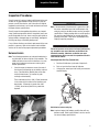
Mark Driveshaft ("Phasing Marks")
It is imperative to mark all the mating components of
a driveshaft, as illustrated below. Mark the driveshaft
with a marking stick, paint marker or other legible
marking device. In addition, be sure to mark all bearing positions, spline positions, shaft locations and all
bearing retainers. This assures proper reassembly of
the driveshaft into the vehicle, in its original position.
Stamped Straps
4.
2.
15
Be sure to ALWAYS use support straps to prevent
the driveshaft from falling out of the vehicle.
It may be necessary to unseat bearing cup assemblies by tapping on yoke or bearing cup with a softfaced hammer. Once the bearing cup assemblies are
free, collapse the driveshaft until both bearing
assemblies clear the open end yoke cross holes.
Allow the driveshaft to rest on support strap.
Driveshaft
2.
Inspect all flange faces for galling or damage. If
damaged, the flange must be replaced.
Grease Zerk Removal and Installation
Remove Grease Zerk Fitting or Plug
1.
5.
Remove bearing retainers or stamped straps and
bolts at the front end.
6.
Inspect all end yoke cross hole surfaces and bolt
hole threads for damage. If the bolt hole threads are
damaged, the yoke must be replaced.
7.
Inspect for raised metal or fretting on open yoke
cross holes can be removed with a fine-toothed file
and/or emery cloth.
Tilt the universal joint kit or flange yoke and universal joint kit to allow access to effected grease zerk
fitting or plug. Using pliers or an open-ended
wrench, turn grease zerk fitting or plug counterclockwise until it is removed from the journal cross.
Discard the grease zerk fitting or plug.
Grease Zerk Fitting Only
Check for threads in the journal. If threads are
present, proceed to next step. If threads are not
present, replacement of universal joint is necessary.
2.
Thoroughly wipe clean the grease zerk fitting or plug
threaded hole.
Install New Grease Zerk Fitting or Plug
3.
Install new grease zerk fitting or plug. Tighten to
minimum 15 ft. lbs. (20 Nm). Then continue to turn
only until grease zerk fitting is correctly positioned.
Slip Member Assembly
Remove Grease Zerk Fitting
1.
Using pliers or an open-ended wrench, turn grease
zerk fitting counter-clockwise until it is removed
from the slip yoke seal. Discard the grease zerk fitting.
2.
Thoroughly wipe clean the grease zerk fitting
threaded hole.
Install New Grease Zerk Fitting
8.
Inspect the end yoke cross holes for distortion and
damage.
3.
Install new grease zerk fitting (Spicer part number
500174-1). Tighten to 31-55 in. lbs. (3.5-6.2 Nm).
Inspect Companion Flange/Flange Yokes
1.
Inspect all flange bolt hole threads or through holes
for damage. If the bolt hole threads or through holes
are damaged, the flange must be replaced.
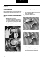
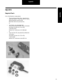
Removal Procedure for Universal Joint Kits
Note: Refer to the Appendix for the recommended list of tools
for the following procedure.
Remove Universal Joint Kit(s)
16
Removal
Note: For removal procedures for companion flanges, refer to
the original equipment manufacturers’ service and maintenance manuals. For removal procedures for flange
yokes, see removel of universal joints in this manual.
Driveshaft
1.
For Snap-Ring Style: Using snap-ring pliers,
remove all snap rings. If snap rings are severely corroded or out-of-round, snap rings must be replaced.
Snap-Ring Style
2.
Make sure universal joints cross assembly is not
tilted in the yoke. Place bearing cup spacer onto the
base of the arbor press and under the yoke. If the
arbor is larger than the bearing cup diameter, a
smaller diameter push rod will be needed to avoid
damaging the yoke or bearing.
Correct Positioning
1.
For Quick Disconnect™ Style: Remove spring tab
bolts and discard, and remove outboard bearing cap
assemblies.
Quick Disconnect™ Style
17
Incorrect Positioning
Driveshaft
3.
1.
Caution - DO NOT over press the bearing cup and
journal cross. This can damage the inside of the
yoke ear.
Inspect the tube yoke and flange yoke (if applicable)
cross hole surfaces for damage or raised metal.
Raised metal or fretting can be removed from yoke
cross holes with a fine-toothed file and/or emery
cloth.
Removal Procedure for Slip Member Boot
4.
5.
The bearing cup is not designed to drop out of the
yoke. Move the partially pressed-out bearing cup
from side to side, to "walk" the bearing cup out of the
yoke ear. Remove the bearing cup from the trunnion.
Place the yoke in the press, with the remaining bearing cup face down. Using a push rod, press on the
end of the journal cross trunnion. Continue to press
down on the journal cross trunnion until the shoulder of the journal cross makes contact with the
inside of the yoke ear.
Mark Driveshaft ("Phasing Marks")
1.
It is imperative to mark all mating components of the
driveshaft. Mark the driveshaft with a marking stick,
paint marker or other legible marking device.
2.
Remove and discard both boot clamps. Clamps may
be separated using a chisel to disengage locking
hooks. DO NOT reuse clamps.
3.
Completely collapse the boot toward the yoke shaft
to expose weld ring and spline sleeve area. Wipe
weld ring and spline sleeve areas clean.
4.
Remove the yoke shaft and boot from the spline
sleeve. Discard boot.
Inspect Tube Yoke and Flange Yoke (if applicable)
18
Removal
Using an arbor press, press down on the upper bearing cup assembly until the shoulder of the journal
cross makes contact with the inside of the yoke ear.
Driveshaft
5.
Inspect the yoke shaft spline surface for damage. If
the splines are damaged, missing or twisted, or any
Glidecote is missing, complete driveshaft replacement is necessary.
6.
Inspect the spline sleeve for damage. If the splines
are damaged, missing or twisted, complete driveshaft replacement is necessary.
7.
Inspect the entire slip assembly for contaminants. If
the slip assembly shows evidence of rust or the lube
is severely contaminated, complete driveshaft
replacement is necessary.
3.
Remove center bearing bracket bolts. Allow coupling shaft to rest on support strap.
4.
Using a puller, follow the tool manufacturer's
instructions to remove the yoke and center bearing
companion flange. Both the yoke and companion
flange are press fit and should NOT be removed with
a hammer. If either the yoke or companion flange
are loose enough to be removed by hand, the entire
coupling shaft must be replaced. Remove and discard slinger from the yoke.
Note: Refer to Slip Member Installation section of this manual
for additional details.
Center Bearing Removal
Remove Midship Nut on Center Bearing Yoke
1.
Mark the counterbore of end yoke to midship "nose"
with marking stick, paint marker or other legible
marking device. This assures proper reassembly of
the center bearing end yoke in its original phased
position.
2.
Remove midship nut. Discard nut. If washer is
damaged, discard and replace. Otherwise, reuse
washer.
DO NOT reuse midship nut. Reuse of midship nut
can cause driveline failure, which can result in separation of driveline from vehicle. A separated driveline can result in property damage, serious personal
injury or death.
Caution - The following step is an additional marking
process to that desribed in the previos section step
one. Be sure to mark as directed.
19
Center Bearing End Yoke Splines Inspection
1.
Visually inspect the splines of the center bearing end
yoke. If the yoke splines are damaged, missing or
twisted, the yoke must be replaced. If the yoke hub
is cracked, the yoke must be replaced.
2.
Visually inspect the midship splines and threads. If
the splines or threads are damaged, missing or
twisted, replacement of the entire coupling shaft is
necessary.
Remove Center Bearing
Driveshaft
1.
4.
Using a puller, follow the tool manufacturer’s
instructions to remove the bearing assembly from
the midship. Discard the center bearing.
Removal
On some Spicer center bearing assemblies, a metal
retainer spans the outside center bearing bracket. If
present, remove the metal retainer and discard.
Inspect Midship Bearing Diameter
2.
3.
5.
Inspect midship for wear on bearing diameter. If
midship is damaged from a seized bearing, replacement of entire coupling shaft is necessary.
6.
If no damage is apparent, remove slinger and discard. Proceed to installation of center bearing.
Remove and discard the center bearing bracket.
Remove and discard rubber cushion.
20
Installation Warnings
Spicer Life Series™ Driveshaft Installation Warnings and Cautions
Before You Get Started
1.
2.
ALWAYS wear safety glasses when performing
maintenance or service. Failure to wear safety
glasses can result in personal injury and/or partial or
complete vision loss.
NEVER go under a vehicle while the engine is running. Be sure the vehicle's engine is off, and keys are
removed from ignition.
3.
NEVER go under or work on a vehicle that is not on a
level or flat surface.
4.
NEVER work on a driveshaft without blocking the
vehicle's wheels and releasing all parking brakes.
See warning below.
5.
NEVER lift a vehicle without the appropriate weightrated, vehicle-support equipment.
6.
NEVER REMOVE a driveshaft from the vehicle without keeping the vehicle's transmission in neutral.
See above warning.
7.
CAUTION – Spicer Life Series™ driveshaft assemblies can weigh in excess of 100 pounds (46 kilograms). Be sure to use proper lifting techniques
when handling Spicer Life Series™ driveshafts. More
than one person may be needed when handling
driveshaft assemblies.
8.
ALWAYS use support straps to prevent the driveshaft
from falling, causing injury and/or damage during
the loosening or removal of any driveshaft hardware.
9.
NEVER heat components or use sledgehammers or
floor jacks to remove the driveshaft from vehicle.
Note: For driveshaft applications that have pillow blocks,
dampers, parking brakes or retarders, refer to these
component manufacturers' or the original equipment
vehicle manufacturers' service manuals for proper procedures.
WARNING
Reassembly of a driveline out of original phase can cause
vibration and failure of the driveline and attaching components. Failure of a driveline can result in separation of
driveline from the vehicle, which can result in property
damage, serious personal injury or death.
Rotating bearing cup assemblies can result in yoke cross
hole wear and distortion. Distorted yokes can result in separation of the driveline from the vehicle.
21
Reuse of spring tab bolts or failure to properly tighten
spring tab bolts to required specifications can cause the
drivline to loosen and separate from the vehicle.
Failure to torque the midship nut to required specifications
can cause driveline failure, which can result in separation
of the driveline from the vehicle.
Reuse of boot clamps or failure to properly tighten boot
clamps to required specifications could allow intrusion of
contaminants onto slip member and can cause driveline
failure, which can result in separation of driveline from the
vehicle.
Attaching or entangling support straps to fuel, oil or brake
lines or wiring can result in their damage. Damaged fuel,
oil or brake lines or wiring can result in failure of the vehicle.
Improperly seated bearing cup assemblies can cause driveline failure, which can result in separation of the driveline
from the vehicle.
Failure to install new stamped straps and new bolts and to
torque bolts to specification can cause driveline failure,
which can result in separation of the driveline from the
vehicle.
Installation of a driveline out of original phase can cause
vibration and failure of the driveline and attaching components. Failure of a driveline can result in separation of the
driveline from the vehicle.
Driveshaft
Universal Joint Installation
2.
Spicer Life Series 55, 70, 90, 100, 350
1.
Using a high quality National Lubricating Grease
Institute E. P. Grade 2 lubricating grease, wipe each
bearing cup assembly with grease. Fill all cavities
between the needle rollers. Also apply a liberal coating of grease on the bottom of each bearing cup
assembly and on the lip of the seal.
Installation
Snap-Ring Style
Position the journal cross into the yoke cross holes
with grease zerk (nipple) fitting inward toward tubing. The double-headed, grease zerk (nipple) fitting
should be perpendicular to the yoke cross holes.
Failure to properly position the universal joint kit will
result in the inability to grease the universal joint.
Note: If using an arbor press, proceed to step 3. If using a
universal joint tool, follow the manufacturer’s instructions.
Note: Refer to Dana information bulletin J3295 for additional
grease specification guidelines.
Caution: Failure to use Dana recommended grease specifications may cause premature component wear and void warranty
coverage.
WARNING
Do not add grease to non-greasable U-joint kits. Mixing
grease types and/or over greasing can cause premature
failures.
Note: Always inspect bearing cups for rollers that may have
fallen (downed rollers) out of place before installation.
Caution - Spicer DOES NOT recommend wiping the outside of
bearing cup assemblies or yoke cross holes with grease, oil or
silicone-based sprays. This could result in bearing cup
assembly rotation in yokes.
3.
Move one end of the journal cross to cause a trunnion to project through the cross hole beyond the
outer machined face of the yoke ear. Place the bearing cup assembly over the protruding trunnion diameter and align it to the yoke cross hole.
4.
Align the yoke in an arbor press with the bearing
assembly resting on the base of the press. Cover the
yoke ear with a metal plate that has 0.25 inch (6.4
mm) minimum thickness. Push the yoke onto the
bearing cup assembly until it is flush with the cross
hole face.
22
Driveshaft
7.
Flip yoke 180 degrees. Place another bearing cup
over trunnion diameter and align it to yoke cross
hole. Align yoke in arbor press with previously
installed bearing cup assembly resting on base of
press. Place a push rod that is smaller than the bearing cup assembly on top of the bearing cup assembly. Press bearing cup assembly into the yoke cross
hole until far enough to install a snap ring.
CAUTION
Bearing caps must be aligned with the trunnion before
pressing to avoid bearing roller and trunnion damage.
5.
6.
23
Place a push rod that is smaller than the diameter of
the bearing cup assembly under the bearing cup
assembly and continue pressing into the yoke cross
hole until far enough to install a snap ring.
Remove yoke from arbor press. Install a snap ring
using snap ring pliers.
8.
Remove yoke from arbor press. Install a snap ring
using snap ring pliers.
9.
Seat installed snap rings into grooves using a small
chisel or punch.
Driveshaft
10. Flex the journal cross to make sure it moves
smoothly and freely in the bearings.
Installation
Note: If the joint is stiff, place a plate on the yoke ear and hit
the plate with a hammer to seat the bearing cup assemblies.
Failure to use Dana recommended grease specifications
may cause premature component wear and void warranty
coverage.
Caution - Spicer DOES NOT recommend wiping the outside of
bearing cup assemblies or yoke cross holes with grease, oil or
silicone-based sprays. This could result in bearing cup
assembly rotation in yokes.
2.
11. Rotate the journal cross to make sure it moves
smoothly and freely in the bearings. If not, disassemble and inspect the journal and bearing assemblies for skewed or dropped needle rollers.
Reference removal procedrues for universal joints,
snap-ring style.
Position the journal cross into the yoke cross holes
with the grease zerk (nipple) fitting inward toward
tubing. The double-headed, grease zerk (nipple) fitting should be perpendicular to the yoke cross holes.
Note: Failure to properly position the universal joint will result
in the inability to grease the universal joint.
Spring Tab Style
Spicer Life Series 140, 170 & 250
1.
Remove needle retaining plugs from all bearing cup
assemblies. Using a high quality National Lubricating Grease Institute E. P. Grade 2 lubricating grease,
wipe each bearing cup assembly with grease. Fill all
cavities between the needle rollers. Also apply a liberal coating of grease on the bottom of each bearing
cup assembly and on the lip of the seal.
Note: Refer to Dana information bulletin J3295 for additional
grease specification guidelines.
Note: Always inspect bearing cups for rollers that may have
fallen (downed rollers) out of place before installation.
CAUTION
24
Driveshaft
3.
Move one end of the journal cross to cause a trunnion to project through the cross hole beyond the
outer machined face of the yoke ear. Take one bearing cup assembly and position an installation height
tool on the end of the bearing cup assembly. Place
the bearing cup assembly over the protruding trunnion diameter and align it to the yoke cross.
6.
Install new spring tabs and 8mm thread bolts. Make
sure that no grease or foreign material is present
between the contact areas of the spring tabs, bearing
cups and yoke cross hole faces. Tighten bolts to the
required torque.
SPRING TAB BOLT SPECIFICATIONS
4.
Align the yoke in an arbor press with the bearing
assembly resting on the base of the press. Cover the
yoke ear with a metal plate that has 0.25 inch (6.4
mm) minimum thickness. Push the yoke onto the
bearing cup assembly until it is flush with the cross
hole face. Do not remove the installation height
tool.
SERIES
THREAD
SIZE
HEAD SIZE
BOLT
Nm
TORQUE
LB. FT.
SPL140
8mm x 1.00
8mm, 6 point
34-41
25-30
SPL170
8mm x 1.00
8mm, 6 point
34-41
25-30
SPL250
8mm x 1.00
8mm, 6 point
34-41
25-30
*Bolts are specially heat-treated.
DO NOT substitute inferior grade bolts.
Center Bearing Installation
5.
25
Flip yoke 180 degrees. Position the remaining
installation heigh tool on the end of another bearing
cup assembly. Place bearing cup assembly over
trunnion diameter and align it to the yoke cross hole.
Push the bearing cup assembly until both installation
height tools are flush with the cross hole face.
1.
Wipe the bearing surface of the midship tube shaft
with a fine emery cloth.
2.
Install a new slinger (included in center bearing
replacement kit) on the midship tube shaft using a
section of tubing to avoid damaging slinger. Make
sure the slinger is completely seated against the
midship tube shaft shoulder
Driveshaft
Note: If the application requires the installation of a slinger,
avoid damage during installation.
3.
Carefully align the new center bearing assembly with
the ground surface of the midship tube shaft. Physically push the center bearing onto the midship tube
shaft.
Install a washer (if required) and new midship nut
and torque nut to specifications. See midship nut
specifications, Table MM.
Installation
Note: Do not reuse old slingers. Most replacement center
bearings will not include slingers.
6.
Failure to torque midship nut to required specifications can
cause driveline failure, which can result in separation of the
driveline from the vehicle. A separated driveline can result in
property damage, serious personal injury or death.
Table MM - Midship Nut Specifications
Series
Head Size
Nut Torque
N· m
Nut Torque
Lbs. Ft.
SPL55
1 5/16"
542-610
400-450
SPL70
1 5/8"
644-712
475-525
SPL90
1 5/8"
644-712
475-525
SPL100
1 5/8"
644-712
475-525
SPL140
41mm*
644-712
475-525
SPL170
41mm*
644-712
475-525
SPL250
41mm*
644-712
475-525
SPL350
41mm*
1100-1300
810-950
Slip Member and Boot Installation
4.
Press remaining slinger on end yoke using a section
of tubing to avoid damaging slinger.
5.
Using a soft-faced hammer, drive the yoke onto midship tube shaft, making sure phasing marks from
driveshaft removal procedure are in line. Continue to
tap the yoke until it is completely seated against the
center bearing.
1.
Clean ALL grease from yoke shaft and spline sleeve.
Make sure grease-cutting solvent does not intrude
into the tube through the vent hole in the spline
sleeve plug. Be sure the phasing marks made during
disassembly are not removed.
Note: Only drive (press) off the washer face of the yoke. Never
hammer or press on the ears of the yoke. See illustration.
26
Driveshaft
2.
After all traces of grease and cutting solvent have
been removed from the yoke shaft and spline sleeve,
apply half of the grease provided to the yoke shaft
splines and the other half to the spline sleeve, cover
the entire splined surface.
failure, which can result in separation of the driveline from
the vehicle.
6.
Before the driveshaft is completely installed in the
vehicle, slowly collapse and extend the driveshaft to
make sure the boot clamps are stationary. If the
clamps are not stationary, recheck for proper clamp
torque. If clamps still are not stationary, repeat disassembly and assembly procedure. DO NOT reuse
clamps.
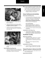
Install Driveshaft
3.
Before installing the driveshaft, inspect the yoke
surface for burrs and damage. Mating surfaces
should be clear of rust, contamination and
grease.
2.
With safety straps in place, align the phasing
marks between the yoke and driveshaft.
3.
Align the bearing cups with the yoke ears making sure that the cups are evenly spaced
between the nibs of the yoke. A soft faced hammer can be used to fully seat the bearing cups
into the yoke.
Measure and place a mark 2.25 inches (55-60mm)
from yoke shaft shoulder with a marking stick, paint
marker or other legible marking device.
4.
Position a clamp on each end of the new boot. Slide
the boot onto the grease-free yoke shaft shoulder.
5.
Collapse the boot and insert the yoke shaft into the
splined sleeve, making sure phasing marks are in
line. Position the end of the boot at the 2.25 inches
(55-60mm) mark made on the yoke shaft shoulder
and tighten boot clamps to the specified torque.
Yoke shaft shoulder must be clean, dry and greasefree.
WARNING
Failure to properly install and tighten boot clamps could
allow intrusion of contaminants and can cause driveline
27
1.
Note: Bearing cups must be fully seated between the yoke
nibs. Failure to seat the cups properly will result in a premature failure.
4.
Install half round straps and lock bolts.
5.
It is important that the strap bolts are torqued in
the correct sequence. Following the diagram
below. Torque the number one bolt before moving to the number two bolt. Always torque in a
counter clockwise direction starting with the
number one position.
Driveshaft
Note: Failure to torque strap bolts in the proper sequence may
cause premature bearing failure.
Installation
Start Here
2
1
1
2
Start Here
6.
Torque strap bolts to specification according to
the chart below.
Bolt Specifications - Quick Disconnect™
Series
Thread
Size
Head
Size
Bolt Torque
Nm
Bolt Torque
Lb. Ft.
SPL 55
SPL 70
SPL 90/100
3/8 - 24
3/8"
12 point
61-81
45-60
SPL 140
SPL 170
SPL 250
12mm 1.25
1/2"
12 point
156-170
115-125
7.
Grease the U-joint and slip member after driveshaft installation. Refer to Lubrication section of
this manual. Refer to Dana information bulletin
J3295 for grease specification guidelines.
28
Glossary
Glossary
Balancing - A procedure by which the mass distribution of a
rotating body is checked, and corrected to insure smooth
operation.
Ball Yoke - See Tube Yoke.
Deflector - See Slinger.
Driveline - An assembly of one or more coupling shafts and a
driveshaft with provisions for axial movement, which transmits torque and/or rotary motion at a fixed or varying angular
relationship from one drivetrain component to another.
Bearing Cross Hole - See Cross Hole.
Bearing Cup Assembly - Consists of a bearing up with needle
rollers generally held in place by a seal guard and bearing
seal. Sometimes the assembly includes a thrust washer.
Bearing Cup - A cup-shaped member used as the bearing
bore of a bearing cup assembly and for positioning a thrust
end of a cross trunnion.
Bearing Retainer - A heavy, formed metal cap used to retain a
bearing cup assembly in Quick Disconnect end yoke or flange
yoke designs.
Bearing Seal - A flexible member of a bearing cup assembly
which prevents the escape of lubricant from or entry of foreign matter into a bearing.
Bearing Strap - Stamped metal strap used to retain a bearing
cup assembly in a half-round end yoke or flange yoke design.
Boot - A flexible member which prevents the escape of lubricant from or entry of foreign matter into the slip spline members.
Boot Clamp - A thin adjustable band used to hold the boot in
position on the slip spline members.
Driveshaft - An assembly of one or two universal joints connected to a tubular shaft member which accomodates axial
movement.
Driveshaft Length (Center Line to Center Line or CL to CL) The distance between the outermost universal joint centers on
a driveshaft. On driveshafts with variable length centers, it is
usually measured in the compressed or installed lengths.
Ear - One of two projecting parts of a yoke symmetrically
located with respect to the yoke’s rotational axis.
End Fitting - An end yoke or companion flange (including
S.A.E>, DIN and T-Type styles) that attaches a driveshaft to
another drivetrain component.
End Yoke - A Quick Disconnect yoke that attaches a driveshaft
to another drivetrain component.
Flange Yoke - A full-round or Quick Disconnect style yoke
which attaches a driveshaft to a companion flange.
Glidecote - The blue, nylon, wear-resistant coating on Spicer
yoke shafts and tube shafts.
Boot Seal - See Boot.
Grease Zerk Fitting - The fitting on the shoulder or center of a
journal cross or on a relubable slip spline that allows for lubrication.
Center Bearing - Consists of a rolling element bearing isolated in rubber and a bracket configuration for attachment to
the vehicle fram.
Inboard Yokes - Yokes that make up the ends of a driveshaft
or coupling shaft assembly, i.e. tube yokes, slip yokes, yoke
shafts, and center bearing end yokes.
Companion Flange - A fixed flange member that attaches the
driveshaft assembly to another drivetrain component.
Installation Height Tools - Round, hard plastic disk that are
supplied with all Spicer Life Series replacement universal joint
kits to ensure proper bearing cup assembly installation specifications.
Coupling Shaft - The coupling member or members of a multiple-piece driveline which includes a center bearing.
Cross - See Journal Cross.
Cross Hole - A through hole in each lug ear of a yoke used to
locate a bearing cup assembly.
29
Journal Cross - The core component of a universal joint
which is an intermediate drive member with four equally
spaced trunnions in the same plane.
Lug Ear - See Ear.
Glossary
Slip Yoke Seal - Pop-on or threaded ring that contains a seal
that protects the slip member assembly from environmental
contaminants and retains lubricant.
Needle Rollers - One of the rolling elements of a bearing cup
assembly.
Snap Ring - A removable member used as a shoulder to
retain and position a bearing cup assembly in a yoke cross
hole.
Outboard Components - Yokes that are not a part of a driveshaft, i.e. transmission, axle, transfer case end yokes and/or
companion flanges.
Snap Ring Groove - A groove used to locate a snap ring.
Phase Angle - The relative rotational position of each yoke on
a driveshaft or driveline.
Spline - A machined element consisting of integral keys
(spline teeth) or keyways (spaces) equally spaced around a
circle or portion thereof.
Pressure Relief Hole - A hold in the welch plug of Spicer slip
yokes that allows air to escape from the slip member assembly.
Spline Sleeve - A tubular-type, machined element consisting
of internal splines which is attached to a tube or tube yoke in a
driveshaft assembly.
Purge - The act of flushing old grease and contaminants from
universal joint kits and slip member assemblies with fresh
grease.
Spring Tab - A patented stamped metal plate that takes the
place of a bearing plate and acts as a structural member by
reducing looseness in a universal joint kit. Found only on
Spicer Life Series driveshaft assemblies.
Quick Disconnect Cross Hole - A semicircular hole located on
the end of each lug ear of some end yoke and flange yoke
designs used to locate a bearing cup assembly.
Stub Shaft - See Tube Shaft.
Retaining Ring - See Snap Ring.
Tang - A nib of metal found on Quick Disconnect end yoke
and/or flange yoke style cross holes, used to locate a bearing
cup assembly.
Retaining Ring Groove - See Snap Ring Groove.
Seal Can - A metal "can" that permanently seals the slip member on a driveshaft. Usually found on European-style driveshaft assemblies.
T-Flange - A companion flange and flange yoke design which
has a serrated flange face. Found most often in European
applications.
T-Type Flange - See T-Flange.
Seal Guard - A covering member used to protect a bearing
seal on the bearing cup assembly.
Serrated Flange - See T-Flange
Shaft Length - Distance between the outermost universal joint
center to joint center.
Shaft Support Bearing - See Center Bearing
Slinger - A stamped metal or non-metal ring which prevents
the entry of foreign matter into a center bearing, transmission,
axle or transfer case.
Slip - The total permissible length of axial travel.
Thrust Washer - A washer found in the bottom of a bearing
cup assembly that reduces needle roller friction, bearing heat
and guards against end galling on the journal cross trunnions.
Tubing - See Tube.
Tube O.D. (outside diameter) - The outside diameter of a
tube.
Tube Yoke - An inboard yoke with a piloting hub for attachment to a tube or spline sleeve.
Tube Shaft - A machined element consisting of spline teeth
and a piloting hub that attaches to the tube of a driveshaft
assembly.
Slip Yoke - A yoke which accomodates axial movement.
Trunnion(s) - Any of the four projecting journals of a cross.
Slip Yoke Plug - See Welch Plug.
30
Glossary
Midship Shaft - A machined element consisting of spline
teeth, a pilot for a center bearing and a piloting hub that
attaches to the tube of a coupling shaft assembly.
Glossary
Universal Joint - A mechanical device which can transmit
torque and/or rotary motion from one shaft to another at fixed
or varying angles of intersection of the shaft axes. Consisting
of a journal cross, fitting and four bearing cup assemblies.
Universal Joint Kit - See Universal Joint.
U-Joint - Universal Joint with installation hardware.
Welch Plug - A plug in the slip yoke face that seals off one
end of the spline opening. Also known as a slip yoke plug.
Weld Yoke - See Tube Yoke.
Yoke Lug Ear Cross Hole - See Cross Hole.
Yoke Shaft - A slip member yoke with a male machined spline
used for axial movement.
31
Appendix
Appendix
Appendix
Required Tools
One of the following is recommended:
•
Three ton minimum, Arbor Press, along with (for
Spicer Life Series 55, 70, 90, 100, 140, 170 & 255)
Bearing Cup Spacer and Push Rod
Metal Plate 0.25 inches (6.4mm) thick,
or
•
J & J Tool Co., Inc. (See photo 104)
Universal Joint Puller Kit 4LIFE - Basic or Complete
(for Spicer Life Series 140, 170 & 250)
1-800-2221-4903
Outside U.S.A. and Canada 1-215-256-9300
or
•
Tiger Tool TGLS-597 (See photo 105) or Mark 10A
(not shown)
(for Spicer Life Series 140, 170 & 250)
1-800-61-4660
Outside U.S.A. and Canada 1-604-855-1133
32
For spec‘ing or service assistance, call 1-877-777-5360 or visit our website at www.dana.com
Dana Commercial Vehicle Products Group
3939 Technology Drive
Maumee, Ohio, USA 43537
www.dana.com
All applications must be approved by the Application Engineering Department. Specifications and/or design are subject to change without notice or obligation.
Printed in USA
DSSM-0100 04/15