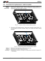
1
APAxxx Series of panel computers for rolling stock Service manual Release 1.00 apaxxx_mr_en_100 APAXXX AMiT, spol. s r.o. does not provide any warranty concerning the contents of this publication and reserves the right to change the documentation without obligation to inform any body or authority about it. This document can be copied and redistributed under following conditions: 1. The whole text (all pages) must be copied without any changes. 2. All redistributed copies must retain the AMiT, spol. s r.o. copyright notice and any other notices contained in the documentation. 3. This document must not be distributed for purpose making of profit. The names of products and companies used herein can be trademarks or registered trademarks of their respective owners. AMiT is a registered trademark. Copyright (c) 2015, AMiT, spol. s r. o. Producer: AMiT, spol. s r. o. Naskové 3/1100, 150 00 Praha www.amit.cz Technical support: [email protected] apaxxx_mr_en_100 2/16 APAXXX Contents History of revisions ......................................................................................... 4 Related documentation................................................................................... 4 1. 2. Introduction .......................................................................................... 5 Disassembling / assembling ............................................................... 6 2.1. 2.2. 2.3. Tools and material .......................................................................................... 6 Disassembling ................................................................................................ 6 Assembling ..................................................................................................... 9 3. Backup battery replacement ............................................................. 10 3.1. 3.2. 3.3. 3.4. Determining location of backup battery module ............................................ 10 Tools and material ........................................................................................ 11 Procedure for replacement – holder for easy replacement ........................... 11 Procedure for replacement – built-in module ................................................ 14 4. 5. Cleaning .............................................................................................. 15 Waste disposal ................................................................................... 16 3/16 apaxxx_mr_en_100 APAXXX History of revisions Document name: apaxxx_mr_en_100.pdf Author: Marian Schaubmar Release 100 Date Changes 31. 3. 2015 New document Related documentation 1. APAxxx Series of panel computers for rolling stock – Operation manual file: apaxxx_g_en_xxx.pdf 2. Backup battery module – Datasheet file: sp_mb247720_d_en_xxx.pdf apaxxx_mr_en_100 4/16 APAXXX 1. Introduction This manual describes the procedure of backup battery replacement, cleaning of internal electronics and disassembling / assembling of APAxxx panel computer series. For most procedures it is necessary to unmount the computer from vehicle, in some cases it is not necessary to disassemble the whole unit. Disassembling / assembling is described in special chapter 2. – Disassembling / assembling. For backup battery replacement and cleaning specifics follow chapters 3. – Backup battery replacement and 4. – Cleaning. 5/16 apaxxx_mr_en_100 APAXXX 2. Disassembling / assembling Disassembling / assembling of the unit consists of unmounting / mounting the computer from the vehicle and disassembling / assembling of the unit electronics. 2.1. Tools and material Tool for releasing screws in the corners of the computer’s front panel (depends on vehicle project). Cross screwdriver PH2 Star screwdriver TORX TX10 Tweezers Weak or middle strength thread locker e.g. LOCTITE 222 (weak strength), LOCTITE 243 (middle strength) 2.2. Disassembling Unmounting 1. Disconnect all the connectors from the computer. from vehicle 2. Unmount the computer from mounting opening in the desk. Computer is fastened by 4 screws in the corners of front panel. Disassembling For access to the backup battery and to the inner electronics of the computer it of the unit is necessary to split the front panel with LCD and back cover which contains the electronics rest of the electronics. Disassembling has to be done on the working table with that surface which cannot cause scratches on parts of panel computer especially display area or front panel foil. See the instructions as follows: 1. Unscrew four M3 head screws in the back cover corners. Use the cross screwdriver of PH2 size. 4x M3 Fig. 1 - Back cover screws 2. After unscrewing of the back cover screws the unit must to lie on the back. We need to lift panel for 5 ÷ 8 cm. Now we have access to inner cabling of LCD screen. We need to VERY CAREFULLY disconnect cables from LCD screen using tweezers. Correct directions for pulling off connectors from apaxxx_mr_en_100 6/16 APAXXX LCD screen are marked by red arrows. See Fig. 2. Repairing of broken connectors caused by wrong handling can be done only by manufacturer. Fig. 2 - Wiring of LCD display 3. Carefully separate panel from the cover with electronics and disconnect remaining 26-wire cable. Connector can be removed only when safety levers on a counterpart connector are unlocked, see Fig. 4. 7/16 apaxxx_mr_en_100 APAXXX Fig. 3 - Splitting of panel and back cover Fig. 4 - Disconnecting of remaining cables 4. Now we can continue to inner electronic cleaning or backup battery replacement. apaxxx_mr_en_100 8/16 APAXXX 2.3. Assembling 1. Connect 26-wire connector between panel and back cover. 2. Panel and back cover must to fit together. Be aware of situation when cables getting stuck between parts of computer. Make sure if 26-wire cable is led thru middle of cooler, see Fig. 5. Fig. 5 - Leading of 26-wire cable 3. Before inserting panel to the back cover connect two remaining cables to the LCD screen. For pressing of connectors to the final position you can use other side of tweezers. 4. For fastening the back cover and panel use screws with split and flat washers. Right order of mounting in direction from the back cover is flat washer, split washer and screw. 5. Now the panel computer is ready for mounting back into the vehicle. 9/16 apaxxx_mr_en_100 APAXXX 3. Backup battery replacement Backup battery is a part of the backup battery module. For ordering information see chapter Ordering information of relevant Operation manual. Some of units may be equipped by backup battery holder for easy replacement. Chapter 3.1. – Determining location of backup battery module can help you to determine position of backup battery module in your unit. 3.1. Determining location of backup battery module If is your unit equipped by backup battery holder for easy replacement as shown in Fig. 6 follow the chapter 3.3. – Procedure for replacement – holder for easy replacement. If isn´t your unit equipped by backup battery holder for easy replacement as shown in Fig. 6 follow the chapter 3.4. – Procedure for replacement – built-in module. Fig. 6 - Possible location of backup battery holder on back cover apaxxx_mr_en_100 10/16 APAXXX 3.2. Tools and material Cross screwdriver PH2 Thread locker for weak or middle strength e.g. LOCTITE 222 (weak strength), LOCTITE 243 (middle strength) 5 mm open end wrench 3.3. Procedure for replacement – holder for easy replacement Battery 1. Unmount the computer from the vehicle. Follow instructions in chapter 2.2. – module Disassembling. Disassembling of the unit isn’t necessary. demounting 2. Unscrew four M3 headed screws which fastens backup battery holder. 4x M3 Fig. 7 - Screws which fastens backup battery holder 11/16 apaxxx_mr_en_100 APAXXX 3. Carefully pull out backup battery holder. Right direction for pulling is marked by red arrow. Fig. 8 - Direction for pulling of backup battery holder Battery 1. Unscrew two M3 headed screws. Screws are secured by thread locker. module Replace the backup battery module with a new one. Secure screws again by replacement thread locker . 2x M3 Fig. 9 - Fixing the battery module in battery module holder apaxxx_mr_en_100 12/16 Fig. 10 - Removing the battery module from the holder APAXXX Battery 1. Attach the backup battery holder on the unit back cover. Watch out for right module orientation of the holder. Male connector on back cover must fit with female mounting connector on backup battery holder. All pins of connectors must be concentric. Wrong handling may cause destroying of battery module ! Fig. 11 - Orientation of attaching the backup battery holder 2. For backup battery holder mounting use four M3 headed screws with split and flat washers. Right order of mounting in direction from the back cover is flat washer, split washer and screw. 13/16 apaxxx_mr_en_100 APAXXX 3.4. Procedure for replacement – built-in module Battery 1. Unmount the computer from the vehicle. Follow instructions in chapter 2.2. – module Disassembling. Backup battery module is located on motherboard close to demounting the buzzer and 26-wire cable connector. Fig. 12 - Location of built-in backup battery module 2. Unscrew two M3 headed screws. Screws are secured by thread locker. It´s recommended to hold the columns using 5 mm open end wrench during screwing. 2x M3 Fig. 13 - Demounting of built-in backup battery module Battery 3. Replace the backup battery module with a new one. module 4. Screw the new module using thread locker. mounting 5. Assemble the computer according to the procedure described in chapter 2.3. – Assembling. apaxxx_mr_en_100 14/16 APAXXX 4. Cleaning There are cleaning ways of APAxxx computer series as follows: Front panel Front panel and display screen area have to be cleaned with dry or wet cloth. cleaning It’s necessary to use cleaning agents which cannot cause scratches on screen area or front panel foil. Computer unmounting from vehicle is not necessary. Electronics cleaning without disassembly Dust settles on panel computer’s electronics and cooler, so thermal transmission between computer parts and ambient air is worse. Because of that dust has to be removed. Without disassembly the removal can be done by vacuum cleaner. Electronics Depending on the dustiness of the environment the cleaning without cleaning with disassembly can be insufficient. disassembly Disassemble the computer according to the procedure described in chapter 2.2. – Disassembling. Cleaning has to be done by dry soft brush or vacuum cleaner. Assemble the computer according to the procedure described in chapter 2.3. – Assembling after cleaning process. 15/16 apaxxx_mr_en_100 APAXXX 5. Waste disposal Battery Backup battery module contains lithium battery. The battery is a dangerous disposal waste. Therefore, it must be delivered to places specified for that purpose. Disposal of empty batteries and accumulators must not be in contrary to valid regulations. apaxxx_mr_en_100 16/16