1
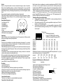
V
-10
0
rol
t
n
l
o
g c ontro
o
l
Ana 512 C
DMX
Sextans
color
multicolor
Your distributor :
USER
manual
Annotation:
Technical specification
Supply voltage
Power consumption
Fuse
Light source
Lamp life
Socket cap
Weight
Dimensions
/mm/
Colours:
Motors:
Electronics:
ProLine Sextans 2PH250
230V/50Hz
560W
T4A
2x120V/250W ENH
175h
Gx5,3
10 kg
370x280x500
dichroic filters
stepping motors
Functions of the device controlled by microprocesor, input controlling
signal 0-10V, input and output signal DMX512. Built in internal
microphone, DIP switch.
Description of the device:
Sextans
Dynamic gobo effect. In dependence of chosen controlling /0-10V/ and
coming sound pulses 6x2 gobo pictures are mapping the area. Gobo
pictures are chosen automatically without sound reaction.. Focusing
/FOCUS/ and size adjusting /ZOOM/ you do by screws on a top of the
device.
DMX controller you adjust speed and course of rotation, chose one of
12 programs
0-10V controller you have possibility of chosing one of 12 programs
/speed and course adjusting, the way of reaction on sound, programs
working with or without sound/
Version: colour Colours and pictures are changing together. In the area 12 gobos in two
colours /of 7 colours/ displays
multicolour
There are changing gobo pictures and displaying in 2x6 colours.
12-central stop without reaction
USER MANUAL
Functions of the control DMX channels
Before you initial start up this lighting, please read the following instructions carefully!
Mode full control DMX512 by signal /8DIP in condition ON/
Important: Damages caused by the disregard of this user manual are not subject to
warranty. We will not accept liability for any resulting defects or problems. There fore,it is
absolutely necessary for you to follow the safety instructions and warning notes written in
this manual.
This lighting is only for power supply 230V/50Hz.
For safety reasons, unauthorized modifications are forbidden! Not only damages to the
lighting can be the result of unauthorized use but also you may endanger your own and
the safety of others.
The electric connection must be carried out by qualified person.
This devise is an effect lighting and was not designed for permanent use.
When you install the lighting, make sure that there is no highly Flammable material in
between a distance of 1m (such as decoration articles, curtains, wooden ceiling etc.
Please keep away from children- lamp generates high temperature.
Lamps are not subject to warranty.
Channel no.1
Channel no.2
0-54
motor no.1 stops
55-155 motor no.1 is rotating to the right/ 55 min. speed, 155- max.
speed /
156-255motor no.1 is rotating to the left / 156 min.speed, 255
max.speed/
0
motors stop
1-54
motor no.2 stops
55-155 motor no.2 is rotating to the right /55 min.speed, 155 max.speed
156-255 motor no.2 is rotating to the left /156 min.speed, 255 max.speed
Mode control adjusting 0-10V /8DIP in condition OFF/
Channel no.1 0-15
PRG1 16-39 PRG2 40-63 PRG3 64-79 PRG4
80-95 PRG5 96-119 PRG6 120-135PRG7 136-159 PRG8 160-175 PRG9
176-207 PRG10
208-223 PRG11
224-255 BlackOut, motors stop
Channel no.2
0
motors stop
1-255 normal mode
Maintenance
Disconnect the device from the mains before any maintenance work!
To secure no failure operation and long lifetime it is essential to clean the device
regularly. Dust with smoke from fog machines, air moisture and cigarette smoke is being
built up on the body of the device, but mainly on optical system objective. Dust penetrates
through the ventilator inside of the device and settles on internal optical system
consequently the light output is reduced radically.
Because there is a bigger danger of failure it is necessary to maintain regularly. Follow
these rules for cleaning:
Objective requires cleaning by soft-cloth moistened in weak soapy solution. Internal
parts, like optical system, gobo, dichroic filters clean monthly the same way, with soft
smooth cloth moistened in weak soapy solution. The gobos clean by soft brush. The
interior of the projector should be cleaned monthly. Ventilator and cooling fans should be
cleaned monthly by soft brush and vacuum cleaner. Adapt cleaning interval to density of
operating time.
Never use for cleaning any solvents and similar chemicals, grinding sponge for
dishwashing, washing powder or cleaning agents with grinding effect.
Ventilation
It is necessary to ensure cooling fans against their covering and secure the device to have
admission of air. If temperature reach 77grd, thermal fuse placed in device will disconnect
of the mains.
Never use device without thermal fuse!!!
Location
Don't install the device at places with mechanical shakings and vibrations, high dustiness
or high temperature. Not keeping these conditions can lead to shorter lifetime or its
damage.
DON´ T expose the device to influence of water, rain or moisture. It could lead to electric
shock or fire.
Supply voltage
Don´t use any other supply voltage meant in technical specification and manufacture
label. Not keeping proper supply voltage could lead to damaging the device,starting a fire
or its wrong function.
Power cord
Check if power cord is not mechanical damaged and if it is connected properly. Check
also if the socket is designed sufficiently for needed loading. Otherwise there is a danger
of electric shock or a fire. Power cord must not be bent excessively, led through sharp
edges or given to mechanical stress. Don´t pull the supply lead out by the flex but only by
the plug. The device must always be connected behind the main switch. Do not touch the
supply lead with vet hands, you are threatened by electric shock.
Other important cautions
Don´t poke any objects into cooling fans and ventilator, it could lead to serious electric
shock or damaging the device. Be careful of no water or other liquid entering.
Maintenance and cleaning
Don´t use any solvent and similar chemicals which could damage surface finish or some
parts of device. Use soft and smooth cloth for cleaning optical parts of device and its
surface. Never use washing powders or other cleaning agents with grinding effect.
Connect the device to power supply after complete drying.
Service
Never try to repair, dismantle or do some construction changes in case of any failure.
Always consult qualified employee or dealer. Not keeping this rule you can suffer
dangerous electric shock. Disconnect the device from mains before replacing the lamp or
dismantling the housing. Not keeping this procedure you can suffer dangerous electric
shock.
Always replace the lamp by consistent with used type or its equivalent.
Unplug mains lead before opening the housing and cleaning internal parts of device.
/optical system, dichroic filters, etc./ You can suffer dangerous damage of sight by
discharge light .
Description of the device
1- external input 0-10V
2 -microphone
3 -XLR /DMX input/
4 -XLR /DMX output/
5 -Power cord
6 -Fuse
7 -LED diode / indication of condition/
8 -DIP switch / function adjusting/
1
2
5
The device offers you several procedure
without controller connection /0-10V, DMX512/ - motors are rotating to the left or
right /PRG1/ according coming pulses
>
with controller connection 0-10V- you have possibilities to adjust one of 12 built in
programs , look at programs 0-10V
>
with controller connection DMX512- you have possibility in dependance of 8DIP
switch to stimulate controlling as a memory 0-10V / it is 12 programs/, or to adjust
course, speed
>
6
3
4
8
7
Unpacking
Unpack the device and after acclimatisation take off the protective foil. Make sure that
there are no damages caused by transportation.
Installation
The device can be installed in any position without altering its operation. For mounting
use bracket of device, which is a mounting hole in. First make sure that the structure you
are going to attach the projector is secure.
When installing the projector over the ground use the safe chain and steel-wire rope as a
double protection against falling down. Make sure the housing is closed firmly with the
screw tightened up.
It is necessary to ensure cooling fans against their covering / curtains etc./ and secure
ventilator and cooling fans to have admission of air.
Before opening the housing always disconnect the device from mains / power cord must
be unplugged from the socket/. Otherwise you can be set to dangerous electric shock.
The device is supplied from manufacturer without light power. These are types of light
power recommended by manufacturer.
version 2PH250- 2xlamp 120V/250W ENH Gx5,3
Procedure
1-Loose fastening screw
2-Pull out the upper cover
3-If you replace the lamp, first take out original one you used before
4-Insert new lamp into the socket. Never touch the glass-bulb discharge lamp barehanded,always use bulb cover or dry cotton cloth or gloves.
5-Make sure that the lamp is installed tightly.
6-Close the cover and tighten fastening screw.
Connection to the mains
The device must always be connected behind the main switch .
Connection to the control signal
Each function of device is addressed according to standard protocol DMX 512 /1990/4
us.It means, we can control this device by any other device, which provides signal
included in protocol DMX 512 by serial line. Connection is secured provided by screened
double-line ended by connector JACK 6,35 /1/4"/ or connector XLR with impedance
120ohm. If cable is not connected to external input 0-10V, the device works according to
program 1 /if 7DIP switch is adjusted well OFF/ and works according coming sound
pulses. If signal DMX 512 is connected to XLR input and if 7DIP is adjusted well-ON ,
functions controlled by 2 DMX consecutive channels.
DIP switch no.
1-6
DMX address(/schedule)
7
Analog (OFF)/ DMX512(ON) controlling
8
full DMX controlling(ON)12 programs (OFF)
ON 1 2 3 4 5 6 7 8
Addressing of the deviceDIP1
Address 1
Address 2
Address3
Address 4
Address 5
Address 6
DIP2
ON
OFF
ON
OFF
ON
OFF
DIP3
ON
ON
OFF
OFF
ON
ON
DIP4
ON
ON
ON
ON
OFF
OFF
DIP5
ON
ON
ON
ON
ON
ON
DIP6
ON
ON
ON
ON
ON
ON
ON
ON
ON
ON
ON
ON
Addressing of the device you make by summary single DIP and by deduction 1. e.g.if you
want to address the device no. 30, adjust by DIP 29.
example
DIP1 DIP2 DIP3 DIP4 DIP5 DIP6 switch
1
2
4
8
16
32
value
device 30
OFF
ON
OFF
OFF
OFF
ON
=sum 29
Programs 0-10V /M1-motor no.1, M2-motor no.2/
Program
description
1-basic mode /work during sound and change course/
2-M1 only to the left, M2 as a prg.1
3-M1 only to the right, M2 as a prg.1
4-as a prg.1 + adjusting of speed
5-M1 stops, M2 as a prg. 1
6-M1, M2 altered with stop
7-M1 as a prg.1, M2 stops
8-M1 as a prg.1 M2 only to the right
9-M1 as a prg.1, M2 only to the left
10-rotation M1to the left, M2 to the right + speed adjusting
11-break movement short fall time, function prg.1
Regulation 0-10V
GND
+10V