1
2004 FORESTER SERVICE MANUAL
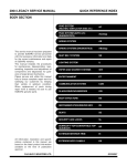
QUICK REFERENCE INDEX
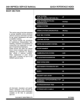
BODY SECTION
This service manual has been prepared
to provide SUBARU service personnel
with the necessary information and data
for the correct maintenance and repair
of SUBARU vehicles.
This manual includes the procedures
for maintenance, disassembling, reassembling, inspection and adjustment of
components and diagnostics for guidance of experienced mechanics.
Please peruse and utilize this manual
fully to ensure complete repair work for
satisfying our customers by keeping
their vehicle in optimum condition.
When replacement of parts during
repair work is needed, be sure to use
SUBARU genuine parts.
All information, illustration and specifications contained in this manual are
based on the latest product information
available at the time of publication
approval.
FUJI HEAVY INDUSTRIES LTD.
HVAC SYSTEM
(HEATER, VENTILATOR AND A/C)
AC
HVAC SYSTEM (AUTO A/C)
(DIAGNOSTIC)
AC
AIRBAG SYSTEM
AB
AIRBAG SYSTEM (DIAGNOSTIC)
AB
SEAT BELT SYSTEM
SB
LIGHTING SYSTEM
LI
WIPER AND WASHER SYSTEM
WW
ENTERTAINMENT
ET
COMMUNICATION SYSTEM
COM
GLASS/WINDOW/MIRROR
GW
BODY STRUCTURE
BS
INSTRUMENTATION/DRIVER INFO
IDI
SEAT
SE
SECURITY AND LOCK
SL
SUNROOF/T-TOP/CONVERTIBLE TOP
(SUNROOF)
SR
EXTERIOR/INTERIOR TRIM
EI
EXTERIOR BODY PANEL
EB
G8080GE7
2004 FORESTER SERVICE MANUAL
QUICK REFERENCE INDEX
BODY SECTION
CRUISE CONTROL SYSTEM
CC
CRUISE CONTROL SYSTEM
(DIAGNOSTIC)
CC(H4SO)
CRUISE CONTROL SYSTEM
(DIAGNOSTIC)
CC(H4DOTC)
CRUISE CONTROL SYSTEM
(DIAGNOSTIC)
CC(H4DOTC 2.5)
IMMOBILIZER (DIAGNOSTIC)
IM
G8080GE7
GLASS/WINDOW/MIRROR
GW
1.
2.
3.
4.
5.
6.
7.
8.
9.
10.
11.
12.
13.
14.
15.
16.
17.
18.
19.
Page
General Description ....................................................................................2
Power Window System ...............................................................................6
Power Window Control Switch ....................................................................7
Remote Control Mirror System..................................................................10
Scalp Cap..................................................................................................11
Outer Mirror Assembly ..............................................................................12
Outer Mirror...............................................................................................14
Remote Control Mirror Switch ...................................................................15
Front Door Glass.......................................................................................17
Front Regulator and Motor Assembly .......................................................21
Rear Door Glass .......................................................................................22
Rear Regulator and Motor Assembly ........................................................24
Windshield Glass ......................................................................................25
Inner Rearview Mirror................................................................................28
Rear Gate Glass .......................................................................................29
Rear Window Defogger System................................................................30
Rear Window Defogger.............................................................................31
Rear Quarter Glass ...................................................................................32
Roof Window Glass...................................................................................34
General Description
GLASS/WINDOW/MIRROR
1. General Description
A: COMPONENT
1. FIXED GLASS
(5) (6)
(2)
(3)
(4)
(10)
(5)
(1)
(9)
(8)
(7)
(3)
(8)
(8)
(6)
(11)
GW-00326
(1)
(2)
(3)
(4)
Windshield glass
Dam rubber
Molding
Rearview mirror mount
(5)
(6)
(7)
(8)
Locate pin
Fastener
Rear quarter glass
Locate pin
GW-2
(9)
(10)
(11)
Rear gate glass
Spring
Cover C pillar
General Description
GLASS/WINDOW/MIRROR
2. FRONT DOOR GLASS
(1)
T1
(4)
T1
(3)
(2)
T2
(5)
(6)
T2
T3
GW-00136
(1)
(2)
(3)
(4)
Glass
Door sash (Front)
Door sash (Rear)
Regulator ASSY
(5)
(6)
Motor ASSY
Guide rail
GW-3
Tightening torque: N·m (kgf-m, ft-lb)
T1: 7.5 (0.75, 5.4)
T2: 14 (1.4, 10.3)
T3: 6 (0.6, 4.3)
General Description
GLASS/WINDOW/MIRROR
3. REAR DOOR GLASS
(2)
(3)
T2
T1
(4)
(1)
T1
T2
(5)
GW-00003
(1)
(2)
(3)
(4)
Door sash (Front)
Glass
Door sash (Rear)
Regulator ASSY
(5)
Motor ASSY
GW-4
Tightening torque: N·m (kgf-m, ft-lb)
T1: 7.5 (0.75, 5.4)
T2: 14 (1.4, 10.3)
General Description
GLASS/WINDOW/MIRROR
4. MIRRORS
(6)
(3)
(5)
(7)
(1)
(3)
(2)
(4)
GW-00298
(1)
(2)
(3)
Outer mirror (Large-sized)
Outer mirror (Standard)
Mirror
(4)
(5)
(6)
Scalp cap
Rearview mirror
Mount
(7)
Spring
B: CAUTION
• When the electrical connectors are disconnected, always conduct an operational check after connecting
them again.
• Avoid impact and damage to glass.
C: PREPARATION TOOL
TOOL NAME
Circuit Tester
Piano Wire
Windshield Knife
REMARKS
Used for checking voltage and continuity.
Used for window glass removal.
Used for window glass removal.
GW-5
Power Window System
GLASS/WINDOW/MIRROR
2. Power Window System
A: WIRING DIAGRAM
1. POWER WINDOW
<Ref. to WI-240, WIRING DIAGRAM, Power Window System.>
B: INSPECTION
Symptom
All power windows does not operate.
One window does not operate.
“Window Lock” does not operate.
Repair order
(1) Fuse (SBF-6) (F/B No. 18)
(2) Power window circuit breaker
(3) Power window relay
(4) Wire harness
(1) Power window main switch
(2) Power window sub switch
(3) Power window motor
(4) Wire harness
Power window main switch
GW-6
Power Window Control Switch
GLASS/WINDOW/MIRROR
3. Power Window Control
Switch
3) Remove the switch panel.
A: REMOVAL
1. MAIN SWITCH
1) Disconnect the ground cable from battery.
2) Using a flat tip screwdriver, remove the screw cover.
GW-00008
4) Disconnect the connector.
B: INSTALLATION
1. MAIN SWITCH
Install in the reverse order of removal.
2. SUB-SWITCH
GW-00327
3) Loosen the screw to remove the power window
main switch.
Install in the reverse order of removal.
GW-00328
4) Disconnect the connector.
2. SUB-SWITCH
1) Disconnect the ground cable from battery.
2) Remove the screw which secures switch panel.
GW-00007
GW-7
Power Window Control Switch
GLASS/WINDOW/MIRROR
C: INSPECTION
1. MAIN SWITCH
Measure the switch resistance.
• LHD model
Switch position
AUTO UP
UP
Driver’s side
OFF
DOWN
AUTO DOWN
UP
Front passenger’s side
OFF
DOWN
UP
Rear LH
OFF
DOWN
UP
Rear RH
OFF
DOWN
Terminal No.
13 and 2, 1 and 5
13 and 2, 1 and 5
1 and 2
1 and 5
2 and 5
13 and 1, 2 and 5
13 and 1, 2 and 5
13 and 7, 6 and 5
5 and 6
5 and 7
6 and 7
13 and 6, 7 and 5
10 and 13, 11 and 5
5 and 11
5 and 10
11 and 10
13 and 11, 10 and 5
13 and 15, 16 and 5
5 and 15
5 and 16
15 and 16
13 and 16, 15 and 5
If NG, replace the main switch.
GW-8
Standard
Less than 1 Ω
Less than 1 Ω
Less than 1 Ω
Less than 1 Ω
Less than 1 Ω
Less than 1 Ω
Less than 1 Ω
Less than 1 Ω
Less than 1 Ω
Less than 1 Ω
Less than 1 Ω
Less than 1 Ω
Less than 1 Ω
Less than 1 Ω
Power Window Control Switch
GLASS/WINDOW/MIRROR
• RHD model
Switch position
AUTO UP
UP
Driver’s side
OFF
DOWN
AUTO DOWN
UP
Front passenger’s side
OFF
DOWN
UP
Rear LH
OFF
DOWN
UP
Rear RH
OFF
DOWN
Terminal No.
12 and 7, 6 and 1
12 and 7, 6 and 1
1 and 6
1 and 7
6 and 7
12 and 6, 7 and 1
12 and 6, 7 and 1
12 and 2, 3 and 1
1 and 2
1 and 3
2 and 3
12 and 3, 2 and 1
12 and 10, 9 and 1
1 and 9
1 and 10
9 and 10
12 and 9, 10 and 1
12 and 14, 13 and 1
1 and 13
1 and 14
13 and 14
12 and 13, 14 and 1
Standard
Less than 1 Ω
Less than 1 Ω
Less than 1 Ω
Less than 1 Ω
Less than 1 Ω
Less than 1 Ω
Less than 1 Ω
Less than 1 Ω
Less than 1 Ω
Less than 1 Ω
Less than 1 Ω
Less than 1 Ω
Less than 1 Ω
Less than 1 Ω
If NG, replace the main switch.
2. SUB-SWITCH
Measure the switch resistance.
Switch position
UP
Front passenger’s side
and rear
OFF
DOWN
Terminal No.
8 and 5, 6 and 7, 1 and 8, 1 and
5
4 and 5, 6 and 7
8 and 7, 4 and 5, 1 and 8, 1 and
7
If NG, replace the sub-switch.
GW-9
Standard
Less than 1 Ω
Less than 1 Ω
Less than 1 Ω
Remote Control Mirror System
GLASS/WINDOW/MIRROR
4. Remote Control Mirror System
A: WIRING DIAGRAM
1. REMOTE CONTROL MIRROR
<Ref. to WI-253, WIRING DIAGRAM, Remote Controlled Rearview Mirror System.>
B: INSPECTION
Symptom
All function does not operate.
One side of the mirror motor does not operate.
Heated mirror does not operate.
Repair order
(1) Fuse (F/B No. 4) (F/B No. 13) (F/B No. 17) (F/B No. 18)
(2) Mirror switch
(3) Wiring harness
(1) Mirror switch
(2) Mirror motor
(3) Wiring harness
(1) Mirror switch
(2) Heated mirror
(3) Wiring harness
GW-10
Scalp Cap
GLASS/WINDOW/MIRROR
5. Scalp Cap
A: REPLACEMENT
1) Turn the rearview mirror downward.
2) Insert a thin screw driver, push the clip part of
scalp cap, and remove the scalp cap.
GW-00224
3) Insert the claw at the bottom of scalp cap into
door mirror.
GW-00299
4) Install the scalp cap securely.
GW-11
Outer Mirror Assembly
GLASS/WINDOW/MIRROR
6. Outer Mirror Assembly
A: REMOVAL
1) Remove the door trim. <Ref. to EI-35, REMOVAL, Front Door Trim.>
2) Remove the mirror gusset cover.
: (1)
GW-00061
(1) Hook
3) Disconnect the mirror connector.
4) Remove the grommet, and then loosen the
screws to remove mirror assembly.
GW-00010
B: INSTALLATION
Install in the reverse order of removal.
GW-12
Outer Mirror Assembly
GLASS/WINDOW/MIRROR
C: INSPECTION
Check to ensure that the rearview mirror moves properly when battery voltage is applied to terminals.
Heated mirror not-equipped model:
Switch position
OFF
UP
DOWN
LEFT
RIGHT
Terminal No.
—
1 (+) and 3 (−)
3 (+) and 1 (−)
2 (+) and 3 (−)
3 (+) and 2 (−)
If NG, replace the mirror.
Heated mirror equipped model:
Switch position
OFF
UP
DOWN
LEFT
RIGHT
Terminal No.
—
2 (+) and 4 (−)
4 (+) and 2 (−)
3 (+) and 4 (−)
4 (+) and 3 (−)
If NG, replace the mirror.
GW-13
Outer Mirror
GLASS/WINDOW/MIRROR
7. Outer Mirror
A: REPLACEMENT
1) Remove the door mirror assembly. <Ref. to GW12, REMOVAL, Outer Mirror Assembly.>
2) Warm the area around the mirror holder (1) with
a hair drier until the edges of the mirror holder become soft (about 2 or 3 minutes with a 1,000 W drier.)
3) Use a flat tip screwdriver without sharp edges to
lift the mirror out of the mirror holder. (Also disconnect the heated mirror connector from the back of
mirror.)
(1)
GW-00062
4) When installing the mirror, warm the area around
the mirror holder with a hair drier until the edges of
the mirror holder become soft again (about 2 or 3
minutes with a 1,000 W drier.)
5) Remove the backing of the new double-stick
tape, and push the mirror in to install it.
NOTE:
Unless the mirror holder is warmed sufficiently, the
mirror holder edges may be damaged or the mirror
cracked.
GW-14
Remote Control Mirror Switch
GLASS/WINDOW/MIRROR
8. Remote Control Mirror
Switch
A: REMOVAL
Refer to Power Window Control Switch, because the
remote control mirror switch is integrated with power
window control switch. <Ref. to GW-7, REMOVAL,
Power Window Control Switch.>
B: INSTALLATION
Refer to Power Window Control Switch, because the
remote control mirror switch is integrated with power
window control switch. <Ref. to GW-7, INSTALLATION, Power Window Control Switch.>
GW-15
Remote Control Mirror Switch
GLASS/WINDOW/MIRROR
C: INSPECTION
Move the rearview mirror switch to each position
and check continuity between terminals.
10 9 8 7 6 5 4 3 2 1
GW-00012
Change over switch right position:
Switch position
OFF
UP
DOWN
LEFT
RIGHT
Terminal No.
—
8 and 3, 6 and 7
8 and 6, 3 and 7
8 and 2, 6 and 7
8 and 6, 2 and 7
Standard
More than 1MΩ
Less than 1Ω
Less than 1Ω
Less than 1Ω
Less than 1Ω
Terminal No.
—
8 and 4, 6 and 7
8 and 6, 4 and 7
8 and 5, 6 and 7
8 and 6, 5 and 7
Standard
More than 1MΩ
Less than 1Ω
Less than 1Ω
Less than 1Ω
Less than 1Ω
Change over switch left position:
Switch position
OFF
UP
DOWN
LEFT
RIGHT
If NG, replace the switch.
GW-16
Front Door Glass
GLASS/WINDOW/MIRROR
9. Front Door Glass
7) Remove the rear end of door weather strip and
weather strip outer.
A: REMOVAL
1) Remove the front door trim. <Ref. to EI-35, REMOVAL, Front Door Trim.>
2) Remove the front speaker. <Ref. to ET-6, REMOVAL, Front Speaker.>
3) Remove the sealing cover. <Ref. to EB-13, REMOVAL, Front Sealing Cover.>
4) Remove the outer mirror assembly. <Ref. to GW12, REMOVAL, Outer Mirror Assembly.>
5) Remove the front end of door weather strip and
gusset.
GW-00015
8) Operate the power window switch to move the
glass to position shown in the figure, and then remove the three nuts from service holes.
GW-00017
9) Take out the door glass.
NOTE:
• Do not turn the regulator in closing direction after
removal of the glass. Otherwise gear may be disengaged.
• Avoid impact and damage to the glass.
GW-00013
6) Remove the stabilizers.
GW-00014
GW-17
Front Door Glass
GLASS/WINDOW/MIRROR
B: INSTALLATION
1) Install in the reverse order of removal.
CAUTION:
Make sure that the glass stay is placed securely
in sash.
2) Adjust the front door glass. <Ref. to GW-18, ADJUSTMENT, Front Door Glass.>
4) For adjustment of clearance between front glass
and center pillar cover, loosen the nuts (A), and
move the rear sash back and forward until clearance becomes the value shown. (Clearance between upper side and lower side is within 1.5 mm
(0.059 in).)
(A)
Tightening torque:
Refer to COMPONENT in General Description. <Ref. to GW-3, FRONT DOOR GLASS,
COMPONENT, General Description.> <Ref. to
GW-2, FIXED GLASS, COMPONENT, General
Description.>
C: ADJUSTMENT
NOTE:
Before adjustment, ensure that all adjusting bolts of
stabilizer, upper stopper and sash are loose and
door glass is raised so that it is in contact with
weather strip.
1) Temporarily tighten one adjusting bolt on one side
of rear sash at the midpoint of slotted hole in the inner panel.
2) Temporarily tighten the regulator B-channel in a
position at the top of slotted hole.
3) Lower the door glass 10 to 15 mm (0.39 to 0.59
in) from fully closed position. While applying outward pressure of 45.0±5 N (4.6±0.5 kg, 11.0±1.1
lb) (F) to upper edge of glass above midpoint of two
outer stabilizers, press the inner stabilizer at pressure of 25±5 N (2.5±0.5 kg, 5.5±1.1 lb) to the glass,
then secure it.
(1)
GW-00019
(1)
(1)
A A
A-A
GW-00064
(1) 12±1 mm (0.472±0.039 in)
5) For adjustment of upper and lower ends of center pillar, loosen the adjusting nut (A) of B-channel
(B).
F
(3)
A
(2)
A
A = A
(A)
(2)
(B)
GW-00063
GW-00021
(1) Full close
(2) Stabilizer
(3) 10 — 15 mm (0.39 — 0.59 in)
GW-18
Front Door Glass
GLASS/WINDOW/MIRROR
6) Adjust so that the upper and lower ends of center pillar are the same size.
For preventing wind noise, adjust the glass at the
position where tip of gusset is raised up a little.
(1)
(3)
(2)
(5)
GW-00024
(A) 0 — 1.5 mm (0 — 0.059 in)
(2)
(4)
8) After stabilizer adjustment, carry out the glass
crimp adjustment. First, visually ensure positional
relationship between retainer & molding and glass
of the roof side, and then begin with rear sash adjustment. Adjust two adjusting bolts alternately step
by step to obtain dimensions shown below (crosssection A).
(1)
NOTE:
If two nuts are loosened at the same time, sash
moves back and forth. Therefore, when one nut is
adjusted, secure the other.
9) Make the same adjustment of two adjusting bolts
of rear sash.
(6)
GW-00139
(1)
(2)
(3)
(4)
(5)
(6)
Narrow
Wide
Glass tilts too far rearward
Glass tilts too far forward
Raise B channel
Lower B channel
(1)
7) For glass stroke adjustment, close the door, raise
glass until positional relationship between glass and
weather strip becomes as shown. And secure the
glass so that the upper stopper lightly touches the
glass holder.
A
A
(2)
(1)
GW-00066
(1) 3.5±0.8 mm (0.137±0.031 in)
(2) 9.5±1 mm (0.374±0.039 in)
A
A
(2)
GW-00066
(1) 3.5±0.8 mm (0.137±0.031 in)
(2) 9.5±1 mm (0.374±0.039 in)
GW-19
Front Door Glass
GLASS/WINDOW/MIRROR
NOTE:
Do not tilt the sash bracket to inner panel during adjustment. Otherwise smooth regulator operation
cannot be achieved.
(1)
(4)
(3)
(2)
(5)
GW-00026
(1)
(2)
(3)
(4)
(5)
Sash bracket
Rear sash
Adjust a line parallel
Rear sash
Inner panel
10) Make adjustment of front sash in the same
manner as that of rear sash.
NOTE:
Although front and rear sashes must, as a rule, be
adjusted in the same manner, in some door installation, the adjustment in a different manner may be
required. However, adjustment of one sash to the
maximum amount and the other to the minimum
amount is not permitted. Such adjustment may result in application of excessive load to regulator.
11) After adjustments, tighten the nuts.
12) After adjustment to glass, close the door. If
there is a gap between outer lip of gusset and glass
surface, adjust the gap with adjusting nut (A) in lower fitting part of the gusset to prevent generation of
wind noise.
13) During adjustments, loosen the other three
clamping screws.
(A)
GW-00056
14) After adjustment, tighten the bolts and nuts.
GW-20
Front Regulator and Motor Assembly
GLASS/WINDOW/MIRROR
10.Front Regulator and Motor
Assembly
C: INSPECTION
A: REMOVAL
1) Remove the door glass. <Ref. to GW-17, REMOVAL, Front Door Glass.>
2) Loosen the nuts to remove rear sash.
1) Make sure that the power window motor rotates
properly when battery voltage is applied to the terminals of motor connector.
2) Change polarity of battery connections to terminals to ensure that the motor rotates in reverse direction.
GW-00027
3) Disconnect the motor connector.
4) Loosen the four bolts and two nuts to remove
regulator assembly.
GW-00028
5) Loosen the screw to remove motor assembly.
GW-00029
B: INSTALLATION
1) Install in the reverse order of removal.
2) Adjust the front door glass. <Ref. to GW-18, ADJUSTMENT, Front Door Glass.>
Tightening torque:
Refer to COMPONENT in General Description. <Ref. to GW-3, FRONT DOOR GLASS,
COMPONENT, General Description.>
GW-21
Rear Door Glass
GLASS/WINDOW/MIRROR
11.Rear Door Glass
6) Loosen the two screws to remove the weather
strip outer.
A: REMOVAL
1) Remove the rear door trim. <Ref. to EI-36, REMOVAL, Rear Door Trim.>
2) Remove the front speaker. <Ref. to ET-6, REMOVAL, Front Speaker.>
3) Remove the sealing cover. <Ref. to EB-16, REMOVAL, Rear Sealing Cover.>
4) Remove the stabilizer.
GW-00030
5) Remove the door weather strip.
GW-00032
7) Operate the power window switch to remove glass
as shown in the figure, and then remove two nuts.
GW-00031
8) Take out the door glass.
CAUTION:
Avoid impact and damage to the glass.
GW-00057
GW-22
Rear Door Glass
GLASS/WINDOW/MIRROR
B: INSTALLATION
2) Adjust the crimp of glass using the following dimensions as a guide line.
1) Install in the reverse order of removal.
CAUTION:
Make sure that the glass stay is placed securely
in sash.
2) Adjust the rear door glass. <Ref. to GW-23, ADJUSTMENT, Rear Door Glass.>
(1)
A
A
Tightening torque:
Refer to COMPONENT in General Description. <Ref. to GW-4, REAR DOOR GLASS,
COMPONENT, General Description.>
(2)
GW-00068
C: ADJUSTMENT
NOTE:
The rear door glass, as a rule, should be adjusted in
the same manner as front glass, although they are
different in dimension. Special notes for the rear
glass are given below.
1) Adjust the glass position using the following dimensions as a guide line. (Clearance between upper side and lower side is within 1.5 mm (0.059 in).)
(1)
A
(1) 3.5±0.8 mm (0.137±0.031 in)
(2) 9.5±1 mm (0.374±0.039 in)
NOTE:
• If the crimp of rear glass is higher than necessary, glass may get caught in weather strip of center pillar corner, resulting in early wear of weather
strip. Be careful when adjusting.
• After adjustment, move the glass up and down to
check whether it is caught.
(1)
A
A-A
GW-00067
(1) 12±1 mm (0.472±0.039 in)
NOTE:
• If the dimensions are smaller than the given dimensions, glass may get caught in weather strip
during lifting/lowering operation. In the worst case, it
may cause the glass not to be opened fully.
• After adjustment, move the glass up and down to
check whether it is caught.
GW-23
Rear Regulator and Motor Assembly
GLASS/WINDOW/MIRROR
12.Rear Regulator and Motor Assembly
A: REMOVAL
1) Remove the door glass. <Ref. to GW-22, REMOVAL, Rear Door Glass.>
2) Remove the front sash.
3) Disconnect the motor connector.
4) Loosen the four bolts and two nuts to remove
regulator assembly.
GW-00035
5) Loosen the screws to remove motor assembly.
GW-00036
B: INSTALLATION
1) Install in the reverse order of removal.
2) Adjust the rear door glass. <Ref. to GW-23, ADJUSTMENT, Rear Door Glass.>
Tightening torque:
Refer to COMPONENT in General Description. <Ref. to GW-4, REAR DOOR GLASS,
COMPONENT, General Description.>
C: INSPECTION
1) Make sure that the power window motor rotates
properly when battery voltage is applied to the terminals of motor connector.
2) Change polarity of battery connections to the terminals to ensure that the motor rotates in reverse
direction.
GW-24
Windshield Glass
GLASS/WINDOW/MIRROR
13.Windshield Glass
A: REMOVAL
(2)
1. USING WINDSHIELD KNIFE
(1)
A
1) Remove the cowl panel. <Ref. to EI-32, REMOVAL, Cowl Panel.>
2) Remove the glass molding.
3) Tape the body side of the circumference of windshield glass for protection.
4) Apply sufficient amount of soapy water to the adhesive layer.
5) Insert the windshield knife into the adhesive layer.
6) While holding the knife edge and windshield glass
edge at a right angle, move the windshield knife in
parallel to the windshield glass edge along face and
edge of windshield glass to cut the adhesive layer.
NOTE:
• Do not twist the windshield knife.
• Cutting of adhesive layer shall be started with
wider gap between windshield glass and body.
• Because the matching pins are bonded to corners of glass, use piano wire to cut the pin.
(1)
(3)
A
A-A
GW-00070
(1) Matching pin
(2) Body panel
(3) Glass
2. USING PIANO WIRE
1) Remove the cowl panel. <Ref. to EI-32, REMOVAL, Cowl Panel.>
2) Remove the roof molding and upper front molding.
3) Tape the body side of the circumference of windshield glass for protection.
4) Make a hole in the adhesive layer using a drill or
knife.
5) Pass the piano wire through the hole, and attach
securely both the wire ends to pieces of wood.
(1)
(1)
A-A
(2)
GW-00039
A
(4)
(3)
A
(3)
GW-00069
(1)
(2)
(3)
(4)
Putty knife
Protective tape
Matching pin
Windshield glass knife
6) Pull the wire ends alternately to cut off the adhesive layer.
CAUTION:
• Do not tightly pull the piano wire against the
windshield glass edge.
• Be careful not to damage the interior and exterior parts.
• When removal is made with area close to instrument panel, place a protection plate over it.
Pay particular attention to the removal.
• Do not cross piano wires. Otherwise they
may be cut.
GW-25
Windshield Glass
GLASS/WINDOW/MIRROR
B: INSTALLATION
4) Apply the dam rubber to back of glass.
1) Clean the external circumference of windshield
glass with alcohol or white gasoline.
2) Remove the adhesive layer on the body using
cutter knife to obtain smooth face 2 mm (0.08 in)
thick.
(4)
CAUTION:
Be careful not to damage the body and paint
surface.
(3)
(1)
(2)
(1)
(3)
(4)
(4)
(2)
(4)
GW-00071
(1)
(2)
(3)
(4)
Adhesive
2 mm (0.08 in)
Dam rubber
Glass
GW-00072
3) Clean the body with alcohol or white gasoline to
remove thoroughly chips, dusts and dirts from body
face.
(1)
(2)
(3)
(4)
Matching pin
Dam rubber
Fastener
13 mm (0.512 in)
5) Remove the backing of double-faced adhesive
tape, and then align the molding mark (B) to notch
(A). Attach the molding around the edge of glass,
and then press it evenly to fit.
GW-00042
GW-26
Windshield Glass
GLASS/WINDOW/MIRROR
6) Apply primer to the adhesive layer of glass using
sponge.
Glass primer:
Dow Automotive
U-401 or U-402
7) Apply primer to the adhesive layer of body.
9) Apply adhesive to the glass end surface as shown.
Adhesive:
Dow Automotive
ESSEX U-400 HV
10) Fit the matching pins using suction rubber cup
to install the windshield glass.
Painted surface primer:
Dow Automotive
U-413
NOTE:
• Primer once attached to the painted surface of
the body and internal trim is hard to wipe off. Mask
the circumference of such areas.
• Let the primer dry for about ten minutes before
installing the glass.
• Do not touch the surface coated with primer.
GW-00045
11) Lightly press the windshield glass for tight fit.
12) Make flush the adhesive surface jutted out using spatula.
13) After completion of all work, allow the vehicle to
stand for about 24 hours.
(1)
(3)
(2)
GW-00073
(1) Application of primer
(2) Glass side
(3) Body side
8) Cut off the cartridge nozzle tip and set it in sealant gun as shown.
NOTE:
• When the door is opened/closed after glass is bonded, always lower the door glass and then open/close it
carefully.
• Move the vehicle slowly.
• For minimum drying time and time the vehicle
must be left standing before driving after bonding,
follow instructions or instruction manual from the adhesive manufacturer.
14) After curing of adhesive, pour water on external
surface of vehicle to check that there are no water
leaks.
NOTE:
When a vehicle is returned to the user, tell him or
her that the vehicle should not be subjected to
heavy impact for at least three days.
15) Install the cowl panel. <Ref. to EI-32, INSTALLATION, Cowl Panel.>
(2)
(1)
(3)
(4)
GW-00074
(1)
(2)
(3)
(4)
10 — 13 mm (0.39 — 0.51 in)
13 mm (0.51 in)
10 mm (0.39 in)
15 mm (0.59 in)
GW-27
Inner Rearview Mirror
GLASS/WINDOW/MIRROR
14.Inner Rearview Mirror
A: REMOVAL
NOTE:
The spring cannot be reused. Prepare a new spring
before removal.
1) Turn the mirror base 90 degrees clockwise or
counterclockwise to remove it.
GW-00046
2) Remove the spring from mirror base.
GW-00047
CAUTION:
Be careful not to damage the mirror surface.
3) If the mirror base is damaged, remove the mirror
base using piano wire or spatula, etc.
CAUTION:
Be careful not to damage the windshield glass.
B: INSTALLATION
1) If removing the mirror base, remove the remaining adhesive thoroughly, and then fit the mirror
base to mark on windshield glass to install.
Adhesive:
REPAIR KIT IN MR (Part No. 65029FC000)
2) Verify that the mirror base is adhered securely,
and then install the spring.
3) Install in the reverse order of removal.
C: INSPECTION
1) Check that the mirror is not damaged.
2) Check that the spring is not damaged.
GW-28
Rear Gate Glass
GLASS/WINDOW/MIRROR
15.Rear Gate Glass
2) Install the glass in same procedure as for windshield glass.
A: REMOVAL
1) Remove the rear gate garnish. <Ref. to EB-20,
REMOVAL, Rear Gate Garnish Assembly.>
2) Remove the electrical connector from rear defogger terminal.
3) Remove the glass in same procedure as for windshield glass. <Ref. to GW-25, REMOVAL, Windshield Glass.>
(1)
(A)
(2)
(3)
(5)
(6)
NOTE:
A matching pin is cemented to corners of the glass
on the compartment side. Use a piano wire when
cutting each pin.
(7)
(4)
(B)
(3)
(2)
(7)
(3)
A
A
(1)
(2)
(4)
(5)
(1)
(8)
(9)
(3)
A-A
GW-00075
GW-00297
A)
B)
(1)
(2)
(3)
(4)
(5)
(6)
(7)
(8)
(9)
(1) Body panel
(2) Glass
(3) Matching pin
B: INSTALLATION
1) Install a new rubber strip (A) by aligning it with
the end of the rear gate glass (B).
(B)
Upper side
Left and right side
Adhesive
Strip rubber
Glass
Primer
12 mm (0.47 in)
14 mm (0.55 in)
10 — 13 mm (0.39 — 0.51 in)
8 mm (0.31 in)
12 mm (0.47 in)
3) About one hour after installation, conduct a leak test.
4) After completion of all work, allow the vehicle to
stand for about 24 hours.
(A)
GW-00049
NOTE:
• When the door is opened/closed after glass is bonded, always lower the door glass and then open/close it
carefully.
• Move the vehicle slowly.
• For minimum drying time and time the vehicle
must be left standing before driving after bonding,
follow instructions or instruction manual from the
adhesive manufacturer.
• When a vehicle is returned to the user, tell him or
her that the vehicle should not be subjected to
heavy impact for at least three days.
5) Connect the rear defogger terminals.
6) Install the rear gate garnish. <Ref. to EB-20, INSTALLATION, Rear Gate Garnish Assembly.>
GW-29
Rear Window Defogger System
GLASS/WINDOW/MIRROR
16.Rear Window Defogger System
A: WIRING DIAGRAM
1. REAR WINDOW DEFOGGER
<Ref. to WI-251, WIRING DIAGRAM, Rear Window Defogger System.>
B: INSPECTION
Symptom
Rear window defogger does not operate.
Repair order
(1) Fuse (M/B No. 1) (F/B No. 17)
(2) Rear defogger relay
(3) Rear defogger timer
(4) Defogger switch
(5) Rear defogger condenser
(6) Defogger wire
(7) Wiring harness
GW-30
Rear Window Defogger
GLASS/WINDOW/MIRROR
17.Rear Window Defogger
A: INSPECTION
CAUTION:
When wiping stain on glass off with cloth, use a
dry and soft cloth and move it in the direction of
heat wire extension to avoid damage to heat
wire.
1) Turn the ignition switch to ON.
2) Turn the defogger switch to ON.
3) Wrap the tips of tester pins with aluminum foil to
avoid damage to heat wire.
5) Apply positive lead of voltmeter to positive terminal
of heat wire, and then move the negative lead along
the wire up to negative terminal end. If voltage changes from zero to several volts during movement of
lead, heat wire is open at the voltage change point.
B: REPAIR
1) Clean the broken portion with alcohol or white
gasoline.
2) Mask both side of wire with thin film.
3) Apply conductive silver composition (DUPONT
No. 4817) to broken portion.
(1)
(4)
(3)
(1)
(3)
(2)
(4)
(2)
GW-00078
GW-00076
(1)
(2)
(3)
(4)
(1)
(2)
(3)
(4)
Tester probe
Tin foil
Heat wire
PRESS
4) Measure the voltage at wire center with DC voltmeter.
4) After repair, check the wire.
Standard voltage:
Approx. 6 V
(1)
GW-00077
(1) Center
Voltage
Approx. 6 V
Approx. 12 V or 0 V
Broken portion
Masking thin film
Broken wire
Conductive silver composition (DUPONT No.
4817)
Criteria
OK
Broken
NOTE:
• If the measured value is 12 volts, heat wire is
open between wire center and positive (+) end.
• If zero volt, heat wire is open between wire center and ground.
GW-31
Rear Quarter Glass
GLASS/WINDOW/MIRROR
18.Rear Quarter Glass
A: REMOVAL
Remove the glass in the same procedure as for windshield glass. <Ref. to GW-25, REMOVAL, Windshield
Glass.>
A
A-A
D-D
(1)
(3)
(4)
(2)
(2)
(4)
B
C
(3)
(1)
D
(5)
(2)
B-B
C-C
(6)
(2)
(3)
(3)
(1)
(7)
(5)
(8)
(5)
GW-00054
(1)
(2)
(3)
Molding
Adhesive
Interior trim
(4)
(5)
(6)
Locating pin
Body
Cover C pillar
B: INSTALLATION
1) Cut off the nozzle tip as shown in the figure.
(1)
(4)
(3)
(2)
(5)
(3)
(6)
(1)
GW-00079
(1)
(2)
(3)
(4)
(5)
(6)
Molding
Matching pin
Adhesive
10 mm (0.39 in)
15 mm (0.59 in)
10 — 13 mm (0.39 — 0.51 in)
(7)
(8)
Weather strip
Rear door glass
2) Install the glass in the same procedure as for windshield glass. <Ref. to GW-26, INSTALLATION,
Windshield Glass.>
3) After completion of all work, allow the vehicle to
stand for about 24 hours.
NOTE:
• When the door is opened/closed after glass is bonded, always lower the door glass and then open/close it
carefully.
• Move the vehicle slowly.
• For minimum drying time and time the vehicle
must be left standing before driving after bonding,
follow instructions or instruction manual from the
adhesive manufacturer.
4) After curing of adhesive, pour water on external
surface of vehicle to check that there are no water
leaks.
GW-32
Rear Quarter Glass
GLASS/WINDOW/MIRROR
NOTE:
When a vehicle is returned to the user, tell him or her
that the vehicle should not be subjected to heavy impact for at least three days.
GW-33
Roof Window Glass
GLASS/WINDOW/MIRROR
19.Roof Window Glass
A: REMOVAL
<Ref. to SR-5, REMOVAL, Sunroof Lid.>
B: INSTALLATION
<Ref. to SR-5, INSTALLATION, Sunroof Lid.>
C: ADJUSTMENT
<Ref. to SR-5, ADJUSTMENT, Sunroof Lid.>
GW-34