1
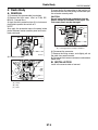
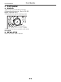
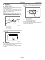
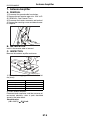
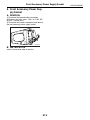
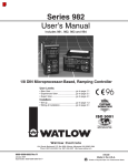
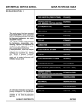
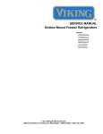
2004 FORESTER SERVICE MANUAL
QUICK REFERENCE INDEX
BODY SECTION
This service manual has been prepared
to provide SUBARU service personnel
with the necessary information and data
for the correct maintenance and repair
of SUBARU vehicles.
This manual includes the procedures
for maintenance, disassembling, reassembling, inspection and adjustment of
components and diagnostics for guidance of experienced mechanics.
Please peruse and utilize this manual
fully to ensure complete repair work for
satisfying our customers by keeping
their vehicle in optimum condition.
When replacement of parts during
repair work is needed, be sure to use
SUBARU genuine parts.
All information, illustration and specifications contained in this manual are
based on the latest product information
available at the time of publication
approval.
FUJI HEAVY INDUSTRIES LTD.
HVAC SYSTEM
(HEATER, VENTILATOR AND A/C)
AC
HVAC SYSTEM (AUTO A/C)
(DIAGNOSTIC)
AC
AIRBAG SYSTEM
AB
AIRBAG SYSTEM (DIAGNOSTIC)
AB
SEAT BELT SYSTEM
SB
LIGHTING SYSTEM
LI
WIPER AND WASHER SYSTEM
WW
ENTERTAINMENT
ET
COMMUNICATION SYSTEM
COM
GLASS/WINDOW/MIRROR
GW
BODY STRUCTURE
BS
INSTRUMENTATION/DRIVER INFO
IDI
SEAT
SE
SECURITY AND LOCK
SL
SUNROOF/T-TOP/CONVERTIBLE TOP
(SUNROOF)
SR
EXTERIOR/INTERIOR TRIM
EI
EXTERIOR BODY PANEL
EB
G8080GE7
2004 FORESTER SERVICE MANUAL
QUICK REFERENCE INDEX
BODY SECTION
CRUISE CONTROL SYSTEM
CC
CRUISE CONTROL SYSTEM
(DIAGNOSTIC)
CC(H4SO)
CRUISE CONTROL SYSTEM
(DIAGNOSTIC)
CC(H4DOTC)
CRUISE CONTROL SYSTEM
(DIAGNOSTIC)
CC(H4DOTC 2.5)
IMMOBILIZER (DIAGNOSTIC)
IM
G8080GE7
ENTERTAINMENT
ET
1.
2.
3.
4.
5.
6.
7.
8.
Page
General Description ....................................................................................2
Radio System..............................................................................................3
Front Accessory Power Supply Socket System ..........................................4
Radio Body..................................................................................................5
Front Speaker .............................................................................................6
Antenna.......................................................................................................7
Antenna Amplifier........................................................................................8
Front Accessory Power Supply Socket .......................................................9
General Description
ENTERTAINMENT
1. General Description
A: CAUTION
• Before disassembling or reassembling parts, always disconnect the battery ground cable. When replacing radio, control module and other parts
provided with memory functions, record memory contents before disconnecting the battery ground cable.
Otherwise, the memory will be erased.
• Reassemble in reverse order of disassembly, unless otherwise indicated.
• Adjust parts to the given specifications.
• Connect the connectors and hoses securely during reassembly.
• After reassembly, make sure functional parts operate smoothly.
B: PREPARATION TOOL
1. GENERAL TOOL
TOOL NAME
Circuit tester
Conductive silver composition
(DUPONT No. 4817 or
equivalent)
REMARKS
Used for measuring resistance and voltage.
Used for repairing antenna
wire.
ET-2
Radio System
ENTERTAINMENT
2. Radio System
A: WIRING DIAGRAM
1. RADIO
<Ref. to WI-101, WIRING DIAGRAM, Audio System.>
B: INSPECTION
Symptom
Repair order
No power coming in. (No display and no sound from speakers.) (1) Check the fuse and power supply for radio.
(2) Check the radio ground.
(3) Remove the radio for repair.
A specific speaker does not operate.
(1) Check the speaker.
(2) Check the output circuit between radio and speaker.
Radio generates noise with engine running.
(1) Check the radio ground.
(2) Check the generator.
(3) Check the ignition coil.
(4) Remove the radio for repair.
AM and FM modes are weak or noisy.
(1) Check the antenna.
(2) Check the antenna amplifier.
(3) Check the noise suppressor.
(4) Check the radio ground.
(5) Remove the radio for repair.
ET-3
Front Accessory Power Supply Socket System
ENTERTAINMENT
3. Front Accessory Power Supply Socket System
A: WIRING DIAGRAM
1. FRONT ACCESSORY POWER SUPPLY
SOCKET SYSTEM
<Ref. to WI-190, WIRING DIAGRAM, Front Accessory Power Supply System.>
ET-4
Radio Body
ENTERTAINMENT
4. Radio Body
5) Insert the flat tip screwdriver to the position (A)
and release the claw with pulling out the lower portion of center console panel.
A: REMOVAL
1) Disconnect the ground cable from battery.
2) Remove the front cover. <Ref. to EI-39, REMOVAL, Console Box.>
3) Apply the thick protective tape (A) to instrument
panel pad to protect the surface of it.
CAUTION:
Do not insert the flat tip screwdriver into any
portion except for indicated in the figure. The
instrument panel may be damaged.
NOTE:
Also apply the protective tape to the deep inside
portion between center console panel and instrument panel pad.
(A)
(A)
EI-00732
(A) Inserting position of flat tip screwdriver
(A)
EI-00731
4) Loosen the screws.
(C)
(C)
6) Disconnect the connector.
7) Remove the fitting screws, and slightly pull out
the radio from center console.
8) Disconnect the harness connectors and antenna
feeder cord.
B: INSTALLATION
Install in the reverse order of removal.
(B)
(A)
(A)
EI-00728
(A) Screw
(B) Clip
(C) Claw
ET-5
Front Speaker
ENTERTAINMENT
5. Front Speaker
A: REMOVAL
1) Disconnect the ground cable from battery.
2) Remove the front door trim. <Ref. to EI-35, REMOVAL, Front Door Trim.>
3) Remove the front speaker mounting screws.
ET-00003
4) Disconnect the harness connector and remove
front speaker.
B: INSTALLATION
Install in the reverse order of removal.
ET-6
Antenna
ENTERTAINMENT
6. Antenna
3) Deposit conductive silver composition (DUPONT No. 4817) on the broken portion with a drawing pen.
A: INSPECTION
Measure the resistance between antenna terminal
and each antenna wire.
If an antenna wire is OK, resistance will be less
than 1 Ω. If an antenna wire is broken, the resistance will be more than 1 MΩ.
(A)
NOTE:
When checking the continuity, wind a piece of aluminum foil around the tip of tester probe and press
aluminum foil against wire with your finger.
(B)
(C)
ET-00009
(A)
(A) Broken portion
(B) Masking thin film
(C) Conductive silver composition
(C)
4) Dry out the deposited portion.
5) After repair has been completed, measure the
resistance in repaired wire.
(B)
ET-00007
(A) Tester probe
(B) Aluminum foil
(C) Antenna wire
To locate the broken point, move the probe along
antenna wire.
ET-00008
B: REPAIR
1) Clean the antenna wire and surrounding area
with a cloth dampened by alcohol.
2) Paste a thin masking film on the glass along broken wire.
ET-7
Antenna Amplifier
ENTERTAINMENT
7. Antenna Amplifier
A: REMOVAL
1) Disconnect the ground cable from battery.
2) Remove the rear quarter upper trim. <Ref. to EI45, REMOVAL, Rear Quarter Trim.>
3) Disconnect the harness connector and terminal.
4) Remove the mounting screws and detach antenna amplifier.
ET-00018
B: INSTALLATION
Install in the reverse order of removal.
C: INSPECTION
Measure the antenna amplifier resistance.
(1)
(2)
(4)
(3)
ET-00019
1) Check cable swagging portion for insulation failure (short).
Terminal No.
1 and Amplifier body
2 and Amplifier body
3 and Amplifier body
4 and Amplifier body
Standard
More than 10 kΩ
More than 10 kΩ
More than 10 kΩ
More than 10 kΩ
2) Check antenna amplifier.
Disconnect each connector, and then measure direct-current electricity value at point described
above by the tester check.
Standard value:
(+B = 13.5 V) ⇒ 50±10 mA
ET-8
Front Accessory Power Supply Socket
ENTERTAINMENT
8. Front Accessory Power Supply Socket
A: REMOVAL
1) Disconnect the ground cable from battery.
2) Remove the front cover. <Ref. to EI-39, REMOVAL, Console Box.>
3) Disconnect the harness connectors and remove
the front accessory power supply socket.
ET-00016
B: INSTALLATION
Install in the reverse order of removal.
ET-9
Front Accessory Power Supply Socket
ENTERTAINMENT
ET-10