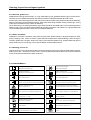
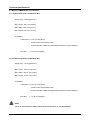
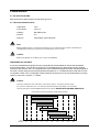
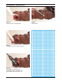
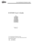
1
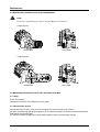
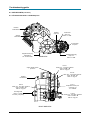
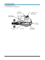
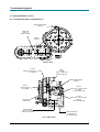
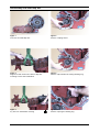
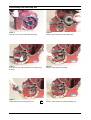
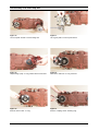
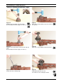
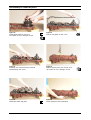
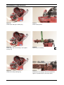
SUPPLEMENT 3 & 4 SHAFT DROP BOX To be used in conjunction with the T12000 3, 4 & 6 Speed Intermediate Drop SPICER OFF-HIGHWAY COMPONENTS CD-ROM: 8100038 MANUAL: 8100039 NOTICE All information mentioned in the maintenance and service manual T12000 powershift transmission 3, 4 & 6 speed Intermediate Drop is valid, unless otherwise specified in this 3 & 4 shaft drop box supplement for the T12000 Intermediate Drop. Copyright DANA CORPORATION 1990. Unpublished material. © All rights reserved. Limited Distribution. No part of this work may be reproduced in any form under any means without direct written permission of the DANA CORPORATION. 3 & 4 Shaft Drop Box 04/01 FOREWORD This manual has been prepared to provide the customer and the maintenance personnel with information and instructions on the maintenance and repair of the SPICER OFF-HIGWAY PRODUCTS product. Extreme care has been exercised in the design, selection of materials, and manufacturing of these units. The slight outlay in personal attention and cost required to provide regular and proper lubrication, inspection at stated intervals, and such adjustments as may be indicated, will be reimbursed many times in low cost operation and trouble-free service. In order to become familiar with the various parts of the product, its principle of operation, troubleshooting and adjustments, it is urged that the mechanic studies the instructions in this manual carefully and uses it as a reference when performing maintenance and repair operations. Whenever repair or replacement of component parts is required, only SPICER OFF-HIGHWAY PRODUCTS approved parts as listed in the applicable parts manual should be used. Use of will-fit or non-approved parts may endanger proper operation and performance of the equipment. SPICER OFF-HIGHWAY PRODUCTS does not warrant repair or replacement parts, nor failures resulting from the use of parts which are not supplied or approved by SPICER OFF-HIGHWAY PRODUCTS. IMPORTANT ALWAYS FURNISH THE DISTRIBUTOR WITH THE SERIAL AND MODEL NUMBER WHEN ORDERING PARTS. 3 & 4 Shaft Drop Box 04/01 3 SHAFT 3 & 4 Shaft Drop Box 04/01 4 SHAFT 3 & 4 Shaft Drop Box 04/01 Table of Content 1. SAFETY PRECAUTIONS ............................................................................................ 1 2. CLEANING, INSPECTION AND LEGEND SYMBOLS ................................................ 1 2.1 CLEANING ...................................................................................................................................... 2.1.1 Bearings ............................................................................................................................... 2.1.2 Housings ............................................................................................................................... 2.2 INSPECTION ................................................................................................................................... 2.2.1 Bearings ............................................................................................................................... 2.2.2 Oil seals, gaskets, etc. ......................................................................................................... 2.2.3 Gears and Shafts .................................................................................................................. 2.2.4 Housing, Covers, etc. ........................................................................................................... 2.3 LEGEND SYMBOLS ........................................................................................................................ 1 1 1 1 1 2 2 2 2 3. TECHNICAL SPECIFICATIONS ................................................................................. 1 3.1 IDENTIFICATION OF THE UNIT ...................................................................................................... 1 3.2.1 Transmission with a 3 shaft Drop Box ................................................................................ 2 3.2.2 Transmission with a 4 shaft Drop Box ................................................................................ 2 3.3 TIGHTENING TORQUES ................................................................................................................. 3 3.3.1 Torque specifications for lubricated or plated screw treads ............................................ 3 3.3.2 Pipe plug torque chart ........................................................................................................ 4 3.3.3 Permanent metric plug torque chart .................................................................................. 4 4. MAINTENANCE ........................................................................................................... 1 4.1 OIL SPECIFICATIONS .................................................................................................................... 1 4.1.1 Recommended lubricants ................................................................................................... 1 4.2 MAINTENANCE INTERVALS FOR THE TRANSMISSION. .............................................................. 3 4.3 MAINTENANCE INTERVALS FOR THE 3 & 4 SHAFT DROP BOX ................................................. 3 4.3.1 Daily ...................................................................................................................................... 3 4.3.2 Normal drain period ............................................................................................................ 3 5 TROUBLESHOOTING GUIDE ..................................................................................... 1 5.1 CHECK POINTS (3 SHAFT DROP BOX .......................................................................................... 5.1.1 Transmission with a 3 shaft drop box ............................................................................... 5.1.2 Transmission with a 3 shaft drop box ................................................................................. 5.1.3 Transmission with a 3 shaft drop box ................................................................................. 5.2 CHECK POINTS (4 SHAFT DROP BOX .......................................................................................... 5.2.1 Transmission with a 4 shaft drop box ................................................................................. 5.2.2 Transmission with a 4 shaft drop box ................................................................................. 5.2.3 Transmission with a 4 shaft drop box ................................................................................. 1 1 2 3 4 4 5 6 6. SECTIONAL VIEWS AND PARTS IDENTIFICATION ................................................. 1 7. ASSEMBLY INSTRUCTIONS ...................................................................................... 1 8 DISASSEMBLY AND REASSEMBLY 3 & 4 SHAFT DROP BOX ................................ 1 3 & 4 Shaft Drop Box 04/01 1. SAFETY PRECAUTIONS To reduce the chance of personal injury and/or property damage, the following instructions must be carefully observed. Proper service and repair are important to the safety of the service technician and the safe reliable operation of the machine. if replacement parts are required, the parts must be replaced by spare parts which have the same part number or with an equivalent part. DO NOT USE A SPARE PART OF LESSER QUALITY. The service procedures recommended in this manual are effective methods for performing service and repair. Some of these procedures require the use of tools specifically designed for the purpose. Accordingly, anyone who intends to use a spare part, service procedure or tool, which is not recommended by SPICER OFF-HIGHWAY PRODUCTS, must first determine that neither his safety nor the safe operation of the machine will be jeopardised by the spare part, service procedure or tool selected. IMPORTANT IT IS IMPORTANT TO NOTE THAT THIS MANUAL CONTAINS VARIOUS CAUTIONS AND NOTICES THAT MUST BE CAREFULLY OBSERVED IN ORDER TO REDUCE THE RISK OF PERSONAL INJURY DURING SERVICE OR REPAIR, OR THE POSSIBILITY THAT IMPROPER SERVICE OR REPAIR MAY DAMAGE THE UNIT OR RENDER IT UNSAFE. IT IS ALSO IMPORTANT TO UNDERSTAND THAT THESE CAUTIONS AND NOTICES ARE NOT EXHAUSTIVE, BECAUSE IT IS IMPOSSIBLE TO WARN ABOUT ALL POSSIBLE HAZARDOUS CONSEQUENCES THAT MIGHT RESULT FROM FAILURE TO FOLLOW THESE INSTRUCTIONS. 3 & 4 Shaft Drop Box 04/01 1-1 2. CLEANING, INSPECTION AND LEGEND SYMBOLS 2.1 CLEANING Clean all parts thoroughly using solvent type cleaning fluid. It is recommended that parts be immersed in cleaning fluid and moved up and down slowly until all old lubricant and foreign material is dissolved and parts are thoroughly cleaned. CAUTION CARE SHOULD BE EXERCISED TO AVOID SKIN RASHES, FIRE HAZARDS, AND INHALATION OF VAPOURS WHEN USING SOLVENT TYPE CLEANERS. 2.1.1 Bearings Remove bearings from cleaning fluid and strike flat against a block of wood to dislodge solidified particles of lubricant. Immerse again in cleaning fluid to flush out particles. Repeat above operation until bearings are thoroughly clean. Dry bearings using moisture-free compressed air. Be careful to direct air stream across bearing to avoid spinning. DO NOT SPIN BEARINGS WHEN DRYING. Bearings may be rotated slowly by hand to facilitate drying process. 2.1.2 Housings Clean interior and exterior of housings, bearing caps, etc... thoroughly. Cast parts may be cleaned in hot solution tanks with mild alkali solutions providing these parts do not have ground or polished surfaces. Parts should remain in solution long enough to be thoroughly cleaned and heated. This will aid the evaporation of the cleaning solution and rinse water. Parts cleaned in solution tanks must be thoroughly rinsed with clean water to remove all traces of alkali. Cast parts may also be cleaned with steam cleaner. CAUTION CARE SHOULD BE EXERCISED TO AVOID INHALATION OF VAPOURS AND SKIN RASHES WHEN USING ALKALI CLEANERS. All parts cleaned must be thoroughly dried immediately by using moistere-free compressed air or soft lintless absorbant wiping rags, free of abrasive materials such as metal fillings, contaminated oil or lapping compound. 2.2 INSPECTION The importance of careful and thorough inspection of all parts cannot be overstressed. Replacement of all parts showing indication of wear or stress will eliminate costly and avoidable failures at a later date. 2.2.1 Bearings Carefully inspect all rollers: cages and cups for wear, chipping, or nicks to determine fitness of bearings for further use. DO NOT REPLACE A BEARING CONE OR CUP INDIVIDUALLY without replacing the mating cup or cone at the same time. After inspection, dip bearings in Automatic Transmission Fluid and wrap in clean lintless cloth or paper to protect them until installed. 3 & 4 Shaft Drop Box 04/01 2-1 Cleaning, Inspection and Legend symbols 2.2.2 Oil seals, gaskets, etc. Replacement of spring load oils seals, O rings, metal sealing rings, gaskets and snap rings is more economical when the unit is disassembled than premature overhaul to replace these parts at a future time. Further loss of lubricant through a worn seal may result in failure of other more expensive parts of the assembly. Sealing members should be handled carefully, particularly when being installed. Cutting, scratching or curling under of lips of seals seriously impairs its efficiency. When assembling new metal type sealing rings, these should be lubricated with a coat of chassis grease to stabilise rings in their grooves for ease of assembly of mating members. Lubricate all O rings and seals with recommended type Automatic Transmission Fluid before assembly. 2.2.3 Gears and Shafts If Magna-Flux process is available, use process to check parts. Examine teeth on all gears carefully for wear, pitting, chipping, nicks, cracks or scores. If gear teeth show spots where case hardening is worn through or cracked, replace with new gear. Small nicks may be removed with suitable hone. Inspect shafts and quills to make certain they are not sprung, bent or spline-twisted, and that shafts are true. 2.2.4 Housing, Covers, etc. Inspect housings, covers and bearing caps to ensure that they are thoroughly clean and that mating surfaces, bearing bores, etc... are free from nicks or burrs. Check all parts carefully for evidence of cracks or conditions which would cause subsequent oil leaks or failures. 2.3 LEGEND SYMBOLS Smontaggio di sottogruppi Sostituire con ogni montaggio Disassembly of assembly groups Renew at each reassembly Montaggio di sottogruppi Togliere - mettere la sicura Reassemble to from assembly group Unlock - lock e.g. split pin, locking plate, etc. Smontaggio di particollari ingombranti Mettere la sicura, incollare (mastice liquido) Remove obstruction parts Lock - adhere (liquid sealant) Montaggio di particollari ingombranti Evitare danni ai materiali, danni ai pezzi Reinstall - remount parts which had obstructed disassembly Guard against material damage, damage to parts Attenzione, indicazione importante Marchiari prima dello smontaggio (per il montaggio) Attention! important notice Mark before disassembly, observe marks when reasembl. Controllare regolare p.e. coppie, misure, pressione etc. Carricare riempire (olio - lubrificante) Check - adjust e.g. torque, dimensions, pressures etc. Filling - topping up - refilling e.g. oil, cooling water, etc. T = Attrezzature speciali Scarricare olio, lubrificante T = Special tool P = Pagina P = Page Drain off oil, lubricant Rispettare direzione di montaggio Tendere Note direction of installation Tighten - clamp ; tightening a clamping device Controllare esaminare controllo visuale Insere pressione nel circuito idraulico Visual inspection Apply pressure into hydraulic circuit Eventualimente riutilizzable (sostituire se necessario) Pulire Possibly still serviceable, renew if necessary To clean 3 & 4 Shaft Drop Box 04/01 2-2 3. TECHNICAL SPECIFICATIONS 3.1 IDENTIFICATION OF THE UNIT 1. Model and Type of the unit 2. Serial number 3 & 4 Shaft Drop Box 04/01 3-1 Technical specifications 3.2 WEIGHT, DIMENSIONS, OIL CAPACITY 3.2.1 Transmission with a 3 shaft Drop Box Weight (dry): ± 255 kg [562 Lbs.] Max. lenght: 529.3 mm [20.84] Max. Width: 872.0 mm [34.33] Max. Heigth: 619.2 mm [24.38] Oil Capacity Transmission: ± 13.5 l [3.6 US gallon] (without cooler and hydraulic lines. Consult Operators Manual on applicable machine for system capacity.) Drop Box: ± 0.75 l [0.2 US gallon] 3.2.2 Transmission with a 4 shaft Drop Box Weight (dry): ± 272 kg [600 Lbs.] Max. lenght: 529.3 mm [20.84] Max. Width: 1007.2 mm [39.66] Max. Heigth: 619.2 mm [24.38] Oil Capacity Transmission: ± 13.5 l [3.6 US gallon] (without cooler and hydraulic lines. Consult Operators Manual on applicable machine for system capacity.) Drop Box: ± 1.0 l [0.26 US gallon] NOTE: THE OIL OF THE DROP BOX IS COMPLETELY SEPARATED FROM THE OIL OF THE TRANSMISSION. 3 & 4 Shaft Drop Box 04/01 3-2 Technical specifications 3.3 TIGHTENING TORQUES 3.3.1 Torque specifications for lubricated or plated screw treads NOM. SIZE GRADE 5 FINE THREAD COARSE THREAD LBF - FT [N.m] LBF - FT [N.m] .2500 9 - 11 [12 - 15] 8 - 10 [11 - 14] .3125 16 - 20 [22 - 27] 12 - 16 [16 - 22] .3750 26 - 29 [35 - 39] 23 - 25 [31 - 34] .4375 41 - 45 [56 - 61] 37 - 41 [50 - 56] .5000 64 - 70 [87 - 95] 57 - 63 [77 - 85] .5625 91 - 100 [123 - 136] 82 - 90 [111 - 122] .6250 128 - 141 [174 - 191] 113 - 124 [153 - 168] .7500 223 - 245 [302 - 332] 200 - 220 [271 - 298] NOM. SIZE GRADE 8 FINE THREAD COARSE THREAD LBF - FT [N.m] LBF - FT [N.m] .2500 11 - 13 [15 - 18] 9 - 11 [12 - 15] .3125 28 - 32 [38 - 43] 26 - 30 [35 - 41] .3750 37 - 41 [50 - 56] 33 - 36 [45 - 49] .4375 58 - 64 [79 - 87] 52 - 57 [71 - 77] .5000 90 - 99 [122 - 134] 80 - 88 [108 - 119] .5625 128 - 141 [174 - 191] 115 - 127 [156 - 172] .6250 180 - 198 [224 - 268] 159 - 175 [216 - 237] .7500 315 - 347 [427 - 470] 282 - 310 [382 - 420] NOM. SIZE GRADE 8.8 or 9.8 GRADE 10.9 COARSE THREAD COARSE THREAD LBF - FT [N.m] LBF - FT [N.m] M10 30 - 37 [40 - 50] 44 - 48 [60 - 65] M12 50 - 55 [65 - 75] 74 - 81 [100 - 110] M16 125 - 140 [170 - 190] 177 - 203 [240 - 275] 3 & 4 Shaft Drop Box 04/01 3-3 Technical specifications 3.3.2 Pipe plug torque chart THREAD NPTF TORQUE LBF - FT [N.m] 1/16-27 5-7 [7-9] 1/8-27 7-10 [9-14] 1/4-18 15-20 [20-27] 3/8-18 25-30 [34-41] 1/2-14 30-35 [41-47] 3/4-10 40-45 [54-61] 3.3.3 Permanent metric plug torque chart THREAD SIZE TORQUE LBF - FT [N.m] M18 x 1.5 6H 25-30 [34-41] M26 x 1.5 6H 45-50 [61-68] 3 & 4 Shaft Drop Box 04/01 3-4 4. MAINTENANCE 4.1 OIL SPECIFICATIONS Both transmission and Drop Box use the same type of oil. 4.1.1 Recommended lubricants 1. Caterpillar TO-4 2. John Deere J20 C, D 3. Military MIL-PRF-2104G 4. Allison C-4 5. Dexron* II Equivalent - See note below Note: DEXRON* II EQUIVALENT IS ACCEPTABLE; HOWEVER IT IS NOT COMPATIBLE WITH TORQUE CONVERTERS OR TRANSMISSIONS EQUIPED WITH GRAPHITIC FRICTION MATERIAL CLUTCH PLATES. Caution: DEXRON* III, ENGINE OIL OR GL-5 OILS ARE NOT RECOMMENDED. PREFERRED OIL VISCOSITY It is recommended that the highest viscosity monograde lubricant available be used for the anticipated ambient temperature. Typically this will be a CAT TO-4 qualified lubricant. When large swings in ambient temerature are possible, J20 C, D multigrades are recommended. Multigrade lubricants should be applied at the lower viscosity rating for the prevailing ambient temperature, i.e. a 10W20 should be used where a 10W monograde is used. If a C-4 multigrade is used instead of J20 lubricant it is recommended that the viscosity spans no more than 10 points, i.e. 10W20. Caution: SYNTHETIC LUBRICANTS ARE APPROVED IF QUALIFIED BY ONE OF THE ABOVE SPECIFICATIONS. OIL VISCOSITY GUIDELINES APPLY, BUT SYNTHETIC MULTIGRADES MAY SPAN MORE THAN FOR FIRE RESISTANT FLUID RECOMMENDATIONS PLEASE CONTACT 10 POINTS. SPICER OFF-HIGHWAY PRODUCTS. Recommended SAE J300 Viscosity Grade Based on Prevailing Ambient Temperature SAE OW20 Dexron* II or equivalent. SAE 10W SAE 20 SAE 30 SAE 40 Celsius Fahrenheit 3 & 4 Shaft Drop Box -40 -40 -30 -22 -20 -4 -10 14 0 32 04/01 10 50 20 68 30 88 40 104 50 122 4-1 Maintenance NORMAL OIL CHANGE INTERVAL Drain and refill system every 1000 hours of average environmental and duty cycle conditions. Severe or sustained high operating temperature or very dusty atmospheric conditions will result in accelerated deterioration or contamination. Judgement must be used to determine the required change intervals for extreme conditions. EXTENDED OIL CHANGE INTERVAL Extended oil service life may result when using synthetic fluids. Appropriate change intervals should be determined for each transmission by measuring oil oxidation and wear metals over time, to determine a baseline. Wear metal analysis can provide useful information, but a transmission should not be removed from service based solely on this analysis. * Dexron is a registered trademark of GENERAL MOTORS CORPORATION. 3 & 4 Shaft Drop Box 04/01 4-2 Maintenance 4.2 MAINTENANCE INTERVALS FOR THE TRANSMISSION. NOTE: TO DRAIN THE TRANSMISSION, BOTH DRAIN PLUGS (A & B) NEED TO BE REMOVED - 3 shaft drop box A B REAR VIEW LEFT VIEW - 4 shaft drop box A B REAR VIEW LEFT VIEW 4.3 MAINTENANCE INTERVALS FOR THE 3 & 4 SHAFT DROP BOX 4.3.1 Daily Check oil level daily. Maintain oil level at full mark. (Middle of oil level glass) 4.3.2 Normal drain period Normal drain period is every 1000 hours for average environment and duty cycle condition. Severe or sustained high operating temperature or very dusty atmospheric conditions will cause accelerated deterioration and contamination. For extreme conditions judgement must be used to determine the required change intervals. 3 & 4 Shaft Drop Box 04/01 4-3 5 TROUBLESHOOTING GUIDE 5.1 CHECK POINTS 5.1.1 Transmission with a 3 shaft drop box Engine speed sensor provision FRONT VIEW Port 32 pressure check port - to cooler 1/8 - 27 NPTF Port 11 to cooler .8750 - 14 UNF - 2B SAE O ring port turbine speed sensor provision Port 31 clutch pressure 1/8 - 27 NPTF Port 45 check port - forward clutch pressure .3750 - 24 UNF - 2B Port 46 check port - reverse clutch pressure .3750 - 24 UNF - 2B transmission oil filler hole mounting holes M12 x 1.75 THD 25.4 mm [1.00] deep magnetic drain plug transmission 3/4 - 14 NPTF THD LEFT SIDE VIEW 3 & 4 Shaft Drop Box 04/01 5-1 Troubleshooting guide 5.1 CHECK POINTS (CONTINUED) 5.1.2 Transmission with a 3 shaft drop box breather transmission breather drop box dipstick transmission oil filler hole drop box M22 x 1.5 THD oil level glass drop box magnetic drain plug transmission 3/4 - 14 NPTF THD REAR VIEW magnetic drain plug drop box M22 x 1.5 THD Port 41 check port - 1st clutch pressure .3750 - 24 UNF - 2B SAE O ring port engine speed sensor provision Port 42 check port - 2nd clutch pressure .3750 - 24 UNF - 2B SAE O ring port breather transmission Port 71 temperature check port converter out 1/4 - 18 NPTF Port 44 check port - 4th clutch pressure .3750 - 24 UNF - 2B SAE O ring port mounting holes M12 x 1.75 THD 25.4 mm [1.00] deep Port 43 check port - 3rd clutch pressure .3750 - 24 UNF - 2B SAE O ring port RIGHT SIDE VIEW 3 & 4 Shaft Drop Box 04/01 5-2 Troubleshooting guide 5.1 CHECK POINTS (CONTINUED) 5.1.3 Transmission with a 3 shaft drop box Port 12 from cooler 1.0625 - 12 UNF - 2B SAE O ring port Port 33 pressure check port - from cooler .3750 - 24 UNF - 2B SAE O ring port lifting eye location M12 x 1.75 THD 22.4 mm [0.880] deep Port 31 clutch pressure 1/8 - 27 NPTF Engine speed sensor provision 3 & 4 Shaft Drop Box TOP VIEW 04/01 Port 31 clutch pressure .3750 - 24 UNF - 2B SAE O ring port 5-3 Troubleshooting guide 5.1 CHECK POINTS (CONTINUED) 5.2.1 Transmission with a 4 shaft drop box Engine speed sensor provision oil filler hole drop box M22 X 1.5 THD breather drop box FRONT VIEW Port 32 pressure check port - to cooler 1/8 - 27 NPTF Port 11 to cooler .8750 - 14 UNF - 2B SAE O ring port turbine speed sensor provision Port 31 clutch pressure 1/8 - 27 NPTF Port 45 check port - forward clutch pressure .3750 - 24 UNF - 2B Port 46 check port - reverse clutch pressure .3750 - 24 UNF - 2B transmission oil filler hole mounting holes M12 x 1.75 THD 25.4 mm [1.00] deep magnetic drain plug transmission 3/4 - 14 NPTF THD LEFT SIDE VIEW 3 & 4 Shaft Drop Box 04/01 5-4 Troubleshooting guide 5.1 CHECK POINTS (CONTINUED) 5.2.2 Transmission with a 4 shaft drop box breather transmission dipstick transmission oil level glass drop box magnetic drain plug transmission 3/4 - 14 NPTF THD REAR VIEW magnetic drain plug drop box M22 x 1.5 THD Port 41 check port - 1st clutch pressure .3750 - 24 UNF - 2B SAE O ring port engine speed sensor provision Port 42 check port - 2nd clutch pressure .3750 - 24 UNF - 2B SAE O ring port breather transmission Port71 temperature check port converter out 1/4 - 18 NPTF Port 44 check port - 4th clutch pressure .3750 - 24 UNF - 2B SAE O ring port mounting holes M12 x 1.75 THD 25.4 mm [1.00] deep Port 43 check port - 3rd clutch pressure .3750 - 24 UNF - 2B SAE O ring port RIGHT SIDE VIEW 3 & 4 Shaft Drop Box 04/01 5-5 Troubleshooting guide 5.1 CHECK POINTS (CONTINUED) 5.2.3 Transmission with a 4 shaft drop box Port 12 from cooler 1.0625 - 12 UNF - 2B SAE O ring port Port 33 pressure check port - from cooler .3750 - 24 UNF - 2B SAE O ring port lifting eye location M12 x 1.75 THD 22.4 mm [0.880] deep Port 31 clutch pressure 1/8 - 27 NPTF Engine speed sensor provision 3 & 4 Shaft Drop Box TOP VIEW 04/01 Port 31 clutch pressure .3750 - 24 UNF - 2B SAE O ring port 5-6 6. SECTIONAL VIEWS AND PARTS IDENTIFICATION 3 & 4 Shaft Drop Box 04/01 6-1 TRANSMISSION CASE & PLATE GROUP 30 28 29 24 25 27 21 19 26 2 13 31 12 8 21 20 4 17 18 16 11 15 3 10 23 14 5 29 28 30 6 7 9 18 1 17 22 3 & 4 Shaft Drop Box 04/01 6-2 TRANSMISSION CASE & PLATE GROUP Item 1 2 3 4 5 6 7 8 9 10 11 12 13 14 15 16 17 18 19 20 21 22 23 24 25 26 27 28 29 30 Description Qty Case - Transmission ................................................................................................................. 1 Breather - Air ............................................................................................................................. 1 Nipple Pipe ............................................................................................................................... 1 Coupling - Pipe .......................................................................................................................... 1 Fitting - Elbow ........................................................................................................................... 1 Plug - Magnetic drain ................................................................................................................ 2 Pin - Plate to transmission case dowel ..................................................................................... 2 Gasket - Plate to transmission case ......................................................................................... 1 Ring - Oil supply tube seal ........................................................................................................ 1 Plate - Spacer ........................................................................................................................... 1 Seat - Safety valve .................................................................................................................... 1 Snapring - Seat ......................................................................................................................... 1 poppet - Converter safety valve .................................................................................................. 1 Spring - Converter safety valve ................................................................................................... 1 Washer - Puppet retaining ......................................................................................................... 1 Plug .......................................................................................................................................... 1 Plug .......................................................................................................................................... 3 O ring - Plug ........................................................................................................................... 3 Screw - Plate to transmission case ........................................................................................... 7 Screw - Plate to transmission case ........................................................................................... 2 Lockwasher - Plate to transmission ........................................................................................... 9 Assembly - Tube & screen ........................................................................................................ 1 Plug -Filler ................................................................................................................................. 1 Plug .......................................................................................................................................... 1 Plug .......................................................................................................................................... 1 Assembly - Dipstick tube .......................................................................................................... 1 Dipstick ..................................................................................................................................... 1 Plug - Speed sensor port ........................................................................................................... 2 O ring - Speed sensor port plug ............................................................................................... 2 Screw - Speed sensor port plug ................................................................................................. 2 3 & 4 Shaft Drop Box 04/01 6-3 3 SHAFT DROP BOX GROUP 17 30 14 15 16 25 26 12 24 13 11 23 31 28 10 27 28 29 2 10 3 20 19 20 18 8 6 1 8 5 9 7 4 13 7 14 17 16 15 9 32 21 22 3 & 4 Shaft Drop Box 04/01 6-4 3 SHAFT DROP BOX GROUP Item 1 2 3 4 5 6 7 8 9 10 11 12 13 14 15 16 17 18 19 20 21 22 23 24 25 26 27 28 29 30 31 32 Description Qty Cover - Drop box front ................................................................................................................ 1 Cover - Drop box rear ................................................................................................................ 1 Gasket - Rear to front cover ....................................................................................................... 1 Shaft - Drop box input ............................................................................................................... 1 Gear - Drop box idler ................................................................................................................. 1 Shaft - Drop box output ............................................................................................................. 1 Bearing - Drop box input shaft ................................................................................................... 2 Bearing - Drop box output shaft ................................................................................................. 2 Bearing - Drop box idler shaft .................................................................................................... 2 Pin - Dowel ............................................................................................................................... 2 Screw - Rear cover to front cover ............................................................................................. 10 Lockwasher - Rear cover to front cover screw .......................................................................... 10 Seal - Drop box output shaft oil ................................................................................................. 2 Flange - Output ......................................................................................................................... 2 O ring - Output flange .............................................................................................................. 2 Washer - Output flange ............................................................................................................. 2 Nut - Output flange .................................................................................................................... 2 Sleeve - Oil seal ........................................................................................................................ 1 O ring - Oil seal sleeve ............................................................................................................ 1 Seal - Oil seal sleeve oil ............................................................................................................ 2 Lockwasher - Drop box mounting screw .................................................................................... 8 Screw - Drop box mounting ....................................................................................................... 8 Glass - Oil level ......................................................................................................................... 1 Plug - Magnetic drain ................................................................................................................ 1 Plug .......................................................................................................................................... 1 O ring - Plug ........................................................................................................................... 1 Sleeve - Pilot ............................................................................................................................. 1 O ring - Sleeve ........................................................................................................................ 2 Ring - Retaining ......................................................................................................................... 1 Breather - Air ............................................................................................................................. 1 Fitting - Elbow 90° street ........................................................................................................... 1 Sticker ...................................................................................................................................... 1 3 & 4 Shaft Drop Box 04/01 6-5 4 SHAFT DROP BOX GROUP 18 16 17 15 13 12 14 32 1 24 3 25 28 27 29 28 11 21 20 19 21 10 9 7 30 6 9 10 31 10 2 14 15 8 5 10 16 18 4 26 8 17 22 GRPT12-214 0201 23 3 & 4 Shaft Drop Box 04/01 6-6 4 SHAFT DROP BOX GROUP Item 1 2 3 4 5 6 7 8 9 10 11 12 13 14 15 16 17 18 19 20 21 22 23 24 25 26 27 28 29 30 31 32 Description Qty Cover - Drop box rear ................................................................................................................ 1 Cover - Drop box front ................................................................................................................ 1 Gasket - Rear to front cover ....................................................................................................... 1 Shaft - Drop box input ............................................................................................................... 1 Shaft - Drop box idler ................................................................................................................ 1 Shaft - Drop box idler ................................................................................................................ 1 Shaft - Drop box output ............................................................................................................. 1 Bearing - Drop box input shaft ................................................................................................... 2 Bearing - Drop box output shaft ................................................................................................. 2 Bearing - Drop box idler shaft .................................................................................................... 4 Pin - Dowel ............................................................................................................................... 2 Screw - Rear cover to front cover ............................................................................................. 13 Lockwasher - Rear cover to front cover screw .......................................................................... 13 Seal - Drop box output shaft ...................................................................................................... 2 Flange - Output ......................................................................................................................... 2 O ring - Output flange .............................................................................................................. 2 Washer - Output flange ............................................................................................................. 2 Nut - Output flange .................................................................................................................... 2 Sleeve - Oil seal ........................................................................................................................ 1 O ring - Oil seal sleeve ............................................................................................................ 1 Seal - Oil seal sleeve oil ............................................................................................................ 1 Lockwasher - Drop box mounting screw .................................................................................... 8 Screw - Drop box mounting ....................................................................................................... 8 Plug - Magnetic drain ................................................................................................................ 1 Glass - Oil level ......................................................................................................................... 1 Plug .......................................................................................................................................... 1 Sleeve - Pilot ............................................................................................................................. 1 O ring - Sleeve ........................................................................................................................ 2 Ring - Retaining ......................................................................................................................... 1 Breather - Air ............................................................................................................................. 1 Fitting - Elbow 90° street ........................................................................................................... 1 Sticker ...................................................................................................................................... 1 3 & 4 Shaft Drop Box 04/01 6-7 7. ASSEMBLY INSTRUCTIONS 3 & 4 Shaft Drop Box 04/01 7-1 7. ASSEMBLY INSTRUCTIONS 3 Shaft Drop Box ± .039 [1] 1 1 1 1 ± 0.435 [11] 3 & 4 Shaft Drop Box Tighten 250 - 300 Lbs.ft [339 - 407 Nm] ± 0.435 [11] 04/01 7-2 Assembly Instructions 7. ASSEMBLY INSTRUCTIONS (CONTINUED) 4 Shaft Drop Box ± .039 [1] 1 1 1 1 ± 0.435 [11] 3 & 4 Shaft Drop Box Tighten 250 - 300 Lbs.ft [339 - 407 Nm] ± 0.435 [11] 04/01 7-3 8 DISASSEMBLY AND REASSEMBLY 3 & 4 SHAFT DROP BOX Note: THIS SECTION SHOWS DISASSEMBLY AND REASSEMBLY OF A 4 SHAFT DROP BOX. THE PROCEDURE IS ALSO VALID FOR THE 3 SHAFT DROP BOX AS IT HAS ONLY ONE IDLER GEAR AND SHAFT, WHEREAS THE 4 SHAFT DROP BOX HAS TWO. Transmission 09/00 1-1 Disassembly of 4 shaft drop box Figure 1 Figure 4 Front view of 4 shaft drop box. Remove coupling sleeve. Figure 2 Figure 5 Support box with chain hoist. Remove drop box mounting screws and lockwashers. Remove output shaft front bearing retaining ring. Figure 3 Figure 6 Pry box from transmission housing. Remove output gear retaining ring. 3 & 4 Shaft Drop Box 04/01 8-2 Disassembly of 4 shaft drop box Figure 7 Figure 10 From the rear, remove output shaft bore plug. Remove output shaft gear and retaining ring. Figure 8 Figure 11 From the front tap output shaft and rear bearing from housing. Remove output shaft front bearing. Figure 9 Figure 12 Output shaft and rear bearing removed. Remove output shaft front bearing retaining ring. 3 & 4 Shaft Drop Box 04/01 8-3 Disassembly of 4 shaft drop box Figure 13 From the rear, remove rear bearing retaining ring. 3 & 4 Shaft Drop Box 04/01 8-4 Disassembly of 4 shaft drop box Figure 14 Figure 17 Use an impact wrench to loosen flange nut. Use a gear puller to remove pilot sleeve. Figure 15 Figure 18 Output flange (rear) O ring, washer and nut removed. Pilot sleeve and inner O ring removed. Figure 16 Figure 19 Remove sleeve outer O ring. Remove coupling sleeve retaining ring. 3 & 4 Shaft Drop Box 04/01 8-5 Disassembly of 4 shaft drop box Figure 20 Figure 23 Use an impact wrench to loosen flange nut. Support front cover with a chain hoist. Pry front cover from rear cover. Figure 21 Figure 24 Output flange (front) O ring, washer and nut removed. Front cover removed. Figure 22 Figure 25 Remove front to rear cover screws and lockwashers. Remove idler shaft and gear. 3 & 4 Shaft Drop Box 04/01 8-6 Disassembly of 4 shaft drop box Figure 26 Figure 29 Remove idler shaft and gear. Output shaft assembly removed. Figure 27 Figure 30 Pry input assembly from cover. If bearing outer races have to be replaced, remove outer races. Figure 28 Figure 31 Input shaft assembly removed. Remove seal sleeve retaining ring. 3 & 4 Shaft Drop Box 04/01 8-7 Disassembly of 4 shaft drop box Figure 32 Tap seal sleeve from cover. Figure 33 Seal sleeve removed. 3 & 4 Shaft Drop Box 04/01 8-8 Reassembly of 4 shaft drop box Refer to Cleaning & Inspection pages. Figure 34 Figure 37 Install two new oil seals in the seal sleeve. See assembly instructions (page 7-2 and 7-3). With new O rings installed. Tap center sleeve into position. Figure 35 Figure 38 Install two new output shaft oil seals in front and rear cover. See assembly instructions (page 7-2 and 7-3). With new O ring installed. Install seal sleeve. Figure 36 Figure 39 Install seal sleeve retaining ring. Install input shaft into rear cover. Use caution as not to damage oil seals. 3 & 4 Shaft Drop Box 04/01 8-9 Reassembly of 4 shaft drop box Figure 40 Figure 43 Install output shaft into rear cover. Use caution as not to damage oil seal. Position new gasket on rear cover. Figure 41 Figure 44 If bearing outer races have been removed, install bearing outer races. Position drop box front cover on rear cover. Use caution as not to damage oil seal. Figure 42 Figure 45 Install idler shafts and gears. Install capscrews and lockwashers. 3 & 4 Shaft Drop Box 04/01 8-10 Reassembly of 4 shaft drop box Figure 46 Tighten screws to specified torque. (See torque chart). Figure 47 Install coupling sleeve retaining ring. 3 & 4 Shaft Drop Box 04/01 8-11 Reassembly of 4 shaft drop box Figure 48 Figure 51 Install output shaft rear bearing locating ring. Install output shaft rear bearing in case against locating ring. Figure 49 Figure 52 Install output shaft front bearing locating ring. Position output shaft. Align splines on shaft with splines in output gear. Tap shaft into position. Figure 50 Figure 53 From the front of transmission case, position output gear with long hub of gear towards the front. Install new bore plug. 3 & 4 Shaft Drop Box 04/01 8-12 Reassembly of 4 shaft drop box Figure 54 Figure 57 Install output shaft gear retaining ring. Install coupling sleeve. Figure 55 Figure 58 Install output shaft front bearing in case against locating ring. Install drop box assembly. Figure 56 Figure 59 Install front bearing retaining ring. Install drop box mounting screws and lockwashers. Tighten to specified torque. (See torque chart). 3 & 4 Shaft Drop Box 04/01 8-13 Reassembly of 4 shaft drop box Figure 60 Figure 63 Install front and rear output flanges. Install breather. Figure 61 Install flange O rings, washers and nuts Figure 62 Block flanges to prevent turning. Tighten flange nuts to specified torque. See assembly instructions page 7-4. 3 & 4 Shaft Drop Box 04/01 8-14