1
Maintenance & Service Manual
TE27 / TE32
Powershift Transmission
4 Speed
Short Drop
SPICER OFF-HIGHWAY COMPONENTS
03/2010
CD-ROM: 8100101
MANUAL: 8100102
Table of Contents
11/2009
1
TOWING OR PUSHING............................................................................................................5
FOREWORD.............................................................................................................................6
1 SAFETY PRECAUTIONS.......................................................................................................7
2 Cleaning, Inspection and Legend symbols ........................................................9
2.1 CLEANING................................................................................................................................... 9
2.1.1 BEARINGS........................................................................................................................... 9
2.1.2 HOUSINGS........................................................................................................................... 9
2.2 Inspection................................................................................................................................ 9
2.2.1 BEARINGS........................................................................................................................... 9
2.2.2 OIL SEALS, GASKETS, etc............................................................................................... 10
2.2.3 GEARS & SHAFTS............................................................................................................ 10
2.2.4 HOUSINGS, COVERS, etc................................................................................................. 10
2.3 LEGEND SYMBOLS.................................................................................................................. 10
3 TECHNICAL SPECIFICATIONS.......................................................................................... 11
3.1. IDENTIFICATION OF THE UNIT............................................................................................... 12
3.2. WEIGHT, DIMENSIONS, OIL CAPACITY.................................................................................. 12
3.3 TIGHTENING TORQUEs.......................................................................................................... 13
3.3.1 Torque specifications for lubricated or plated screw threads...................................... 13
3.3.2 Elastic stop nut torque..................................................................................................... 15
3.3.3 Torque tables for plugs (“o”-ring ports)......................................................................... 15
3.3.4 Torque tables for pipe plugs............................................................................................ 15
3.3.5 Permanent metric plug torque chart .............................................................................. 15
3.4 PRESSURE & TEMPERATURE SPECIFICATIONS.................................................................. 16
3.5 Electrical specifications............................................................................................... 17
3.6 Hydraulic cooler lines specifications.................................................................... 17
4 MAINTENANCE...................................................................................................................18
4.1. Oil specification................................................................................................................. 19
4.1.1 Recommended lubricants................................................................................................ 19
4.1.2 Normal oil change interval............................................................................................... 19
4.2 MAINTENANCE INTERVALS..................................................................................................... 19
4.2.1 Daily.................................................................................................................................... 19
4.2.2Clutch calibration............................................................................................................... 19
4.3 Servicing machine after components overhaul.................................................. 20
4.4 Procedure for performing automatic calibration............................................ 21
4.4.1 Introduction....................................................................................................................... 21
4.4.2 running the automatic calibration................................................................................... 21
4.4.2.1 How to enter the calibration mode.......................................................................... 21
4.4.3 PERFORMING AN AUTOMATIC CALIBRATION.............................................................. 22
4.4.4 HEATING UP THE TRANSMISSION BY USING THE ‘HEAT’-MODE.............................. 23
4.4.5 CALIBRATION CONDITION MESSAGES AND CALIBRATION ERRORS...................... 25
TE27/32 4 SD
03/2010
4.4.5.1 Calibration condition messages.............................................................................. 25
4.4.5.2 Calibration errors...................................................................................................... 25
4.4.6 PERFORMING A STALL TEST.......................................................................................... 26
5 Installation details....................................................................................................28
5.1 Converter drive coupling . ......................................................................................... 28
5.2 TRANSMISSION TO ENGINE INSTALLATION PROCEDURE............................................. 29
5.3 External plumbing............................................................................................................ 30
5.3.1 Cooler & filter lines specifications.................................................................................. 30
5.4 speed sensor installation............................................................................................. 31
6 Transmission Operation............................................................................................34
6.1 The transmission assembly............................................................................................ 34
6.1.1 The converter, pump drive section and pressure regulating valve.............................. 35
6.1.2 The input shaft and directional clutches........................................................................ 36
6.1.3 The range clutches .......................................................................................................... 37
6.1.4The output section............................................................................................................. 37
6.2 The transmission controls (refer to hydraulic diagram)............................ 38
6.3 Electric solenoid controls......................................................................................... 39
6.4 Powerflows, activated solenoids and hydraulic circuit.............................. 40
6.4.1 Neutral-1 Selected............................................................................................................. 40
6.4.2 Forward 1st speed............................................................................................................ 42
6.4.3 Forward 2nd speed........................................................................................................... 44
6.4.4 Forward 3rd speed............................................................................................................ 46
6.4.5 Forward 4TH speed........................................................................................................... 48
6.4.6 Reverse 1st speed............................................................................................................. 51
6.4.8 Reverse 3rd speed............................................................................................................ 54
6.4.9 Reverse 4TH speed........................................................................................................... 56
7 Troubleshooting guide.............................................................................................60
7.1 The Transmission................................................................................................................ 60
7.2 The input shaft and directional clutches............................................................. 60
7.2.1 Stall test............................................................................................................................. 60
7.2.2 Transmission pressure checks........................................................................................ 61
7.2.3 Mechanical and electrical checks.................................................................................... 61
7.2.4 Hydraulic checks............................................................................................................... 61
7.2.5 Controller (APC200): Please refer to functional description........................................ 61
7.3 TROUBLESHOOTING GUIDE................................................................................................... 62
7.3.1 Low clutch pressure........................................................................................................ 62
7.3.2 Low charging pump output flow..................................................................................... 62
7.3.3 Overheating..................................................................................................................... 62
7.3.4 Noisy converter............................................................................................................... 62
7.3.5 Lack of power.................................................................................................................. 62
7.4 CHECK POINTS....................................................................................................................... 63
7.5 SPEED SENSOR - STATIC STANDALONE TEST.................................................................... 67
7.6 Full flow valve components...................................................................................... 68
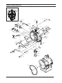
8 SECTIONAL VIEWS & PARTS IDENTIFICATION..............................................................69
TE27/32 4 SD
03/2010
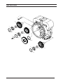
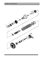
TORQUE CONVERTER GROUP..................................................................................................... 70
TRANSMISSION CASE & REAR COVER GROUP......................................................................... 72
TURBINE SHAFT GROUP............................................................................................................... 74
PUMP DRIVE GROUP...................................................................................................................... 76
Adaptor sleeve group........................................................................................................... 78
Wheel group............................................................................................................................... 80
FLEX PLATE group...................................................................................................................... 82
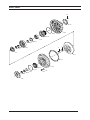
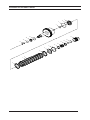
FWD & REV/2nd and 3th or 4th clutch shaft assy........................................................ 84
forward clutch shaft GROUP............................................................................................. 86
3rd speed clucth shaft GROUP........................................................................................... 88
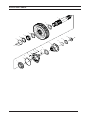
3rd speed gear.......................................................................................................................... 90
REV / 2nd schaft GROUP........................................................................................................... 92
1st speed clutch shaft GROUP............................................................................................ 94
4th speed clutch shaft GROUP........................................................................................... 96
1st shaft gear GROUP............................................................................................................. 98
Output shaft GROUP.............................................................................................................. 100
Regulator valve group....................................................................................................... 102
control valve GROUP............................................................................................................ 104
remote filter adapter GROUP........................................................................................... 106
9 assembly instructions............................................................................................109
10 Disassembly of transmission (under construction)............................... 116
11 SPECIAL TOOL................................................................................................................190
TE27/32 4 SD
03/2010
TOWING OR PUSHING
Before towing the vehicle, be sure to disconnect the driveline to avoid damage to the transmission during towing.
Note:
Because of the design of the hydraulic system, the engine cannot be started by pushing or towing.
Copyright DANA CORPORATION 1990. Unpublished material.
©
All rights reserved. Limited Distribution.
No part of this work may be reproduced in any form under any means without direct written permission of the DANA CORPORATION
TE27/32 4 SD
03/2010
5
FOREWORD
This manual has been prepared to provide the customer and the maintenance personnel with information and
instructions on the maintenance and repair of the SPICER OFF-HIGWAY PRODUCTS product.
Extreme care has been exercised in the design, selection of materials, and manufacturing of these units. The
slight outlay in personal attention and cost required to provide regular and proper lubrication, inspection at stated
intervals, and such adjustments as may be indicated, will be reimbursed many times in low cost operation and
trouble-free service.
In order to become familiar with the various parts of the product, its principle of operation, troubleshooting and
adjustments, it is urged that the mechanic studies the instructions in this manual carefully and uses it as a reference when performing maintenance and repair operations.
Whenever repair or replacement of component parts is required, only SPICER OFF-HIGHWAY PRODUCTS approved parts as listed in the applicable parts manual should be used. Use of “will-fit” or non-approved parts may
endanger proper operation and performance of the equipment. SPICER OFF-HIGHWAY PRODUCTS does not
warrant repair or replacement parts, nor failures resulting from the use of parts which are not supplied or approved by SPICER OFF-HIGHWAY PRODUCTS.
IMPORTANT
ALWAYS FURNISH THE DISTRIBUTOR WITH THE SERIAL AND MODEL NUMBER WHEN
ORDERING PARTS.
TE27/32 4 SD
03/2010
6
1 SAFETY PRECAUTIONS
To reduce the chance of personal injury and/or property damage, the following instructions must be carefully
observed.
Proper service and repair are important to the safety of the service technician and the safe reliable operation of
the machine. if replacement parts are required, the parts must be replaced by spare parts which have the same
part number or with equivalent parts. DO NOT USE A SPARE PART OF LESSER QUALITY.
The service procedures recommended in this manual are effective methods for performing service and repair.
Some of these procedures require the use of tools specifically designed for the purpose.
Accordingly, anyone who intends to use a spare part, service procedure or tool, which is not recommended by
SPICER OFF-HIGHWAY PRODUCTS, must first determine that neither his safety nor the safe operation of the
machine will be jeopardised by the spare part, service procedure or tool selected.
IMPORTANT
IT IS IMPORTANT TO NOTE THAT THIS MANUAL CONTAINS VARIOUS ‘CAUTIONS AND NOTICES’ THAT
MUST BE CAREFULLY OBSERVED IN ORDER TO REDUCE THE RISK OF PERSONAL INJURY DURING
SERVICE OR REPAIR, OR THE POSSIBILITY THAT IMPROPER SERVICE OR REPAIR MAY DAMAGE THE
UNIT OR RENDER IT UNSAFE.
IT IS ALSO IMPORTANT TO UNDERSTAND THAT THESE ‘ CAUTIONS AND NOTICES’ ARE NOT EXHAUSTIVE, BECAUSE IT IS IMPOSSIBLE TO WARN ABOUT ALL POSSIBLE HAZARDOUS CONSEQUENCES
THAT MIGHT RESULT FROM FAILURE TO FOLLOW THESE INSTRUCTIONS.
TE27/32 4 SD
03/2010
1-7
2 CLEANING and inspection
TE27/32 4 SD
03/2010
2-8
2 Cleaning, Inspection and Legend symbols
2.1 CLEANING
Clean all parts thoroughly using solvent type cleaning fluid. It is recommended that parts be immersed in cleaning fluid and moved up and down slowly until all old lubricant and foreign material is dissolved and parts are
thoroughly cleaned.
CAUTION
CARE SHOULD BE EXERCISED TO AVOID SKIN RASHES, FIRE HAZARDS, AND INHALATION OF
VAPOURS WHEN USING SOLVENT TYPE CLEANERS.
2.1.1 BEARINGS
Remove bearings from cleaning fluid and strike flat against a block of wood to dislodge solidified particles of
lubricant. Immerse again in cleaning fluid to flush out particles. repeat above operation until bearings are thoroughly clean. Dry bearings using moisture-free compressed air. Be careful to direct air stream across bearing to
avoid spinning. Do not spin bearings when drying. Bearings may be rotated slowly by hand to facilitate
drying process.
2.1.2 HOUSINGS
Clean interior and exterior of housings, bearing caps, etc... thoroughly. Cast parts may be cleaned in hot solution
tanks with mild alkali solutions providing these parts do not have ground or polished surfaces.
Parts should remain in solution long enough to be thoroughly cleaned and heated. This will aid the evaporation
of the cleaning solution and rinse water. Parts cleaned in solution tanks must be thoroughly rinsed with clean
water to remove all traces of alkali. Cast parts may also be cleaned with steam cleaner.
CAUTION
CARE SHOULD BE EXERCISED TO AVOID INHALATION OF VAPOURS AND SKIN RASHES WHEN
USING ALKALI CLEANERS.
All parts cleaned must be thoroughly dried immediately by using moistere-free compressed air or soft lintless
absorbant wiping rags, free of abrasive materials such as metal fillings, contaminated oil or lapping compound.
2.2 Inspection
The importance of careful and thorough inspection of all parts cannot be overstressed. replacement of all parts
showing indication of wear or stress will eliminate costly and avoidable failures at a later date.
2.2.1 BEARINGS
Carefully inspect all rollers: cages and cups for wear, chipping, or nicks to determine fitness of bearings for further use. DO NOT REPLACE A BEARING CONE OR CUP INDIVIDUALLY without replacing the mating cup or
cone at the same time. After inspection, dip bearings in Automatic Transmission Fluid and wrap in clean lintless
cloth or paper to protect them until installed.
TE27/32 4 SD
03/2010
2-9
Cleaning and Inspection & Legend symbols
2.2.2 OIL SEALS, GASKETS, etc.
Replacement of spring load oils seals, “O” rings, metal sealing rings, gaskets and snap rings is more economical
when the unit is disassembled than premature overhaul to replace these parts at a future time.
Further loss of lubricant through a worn seal may result in failure of other more expensive parts of the assembly.
Sealing members should be handled carefully, particularly when being installed. Cutting, scratching or curling
under of lips of seals seriously impairs its efficiency.
When assembling new metal type sealing rings, these should be lubricated with a coat of chassis grease to
stabilise rings in their grooves for ease of assembly of mating members. Lubricate all “O” rings and seals with
recommended type Automatic Transmission Fluid before assembly.
2.2.3 GEARS & SHAFTS
If Magna-Flux process is available, use process to check parts. Examine teeth on all gears carefully for wear,
pitting, chipping, nicks, cracks or scores. If gear teeth show spots where case hardening is worn through or
cracked, replace with new gear. Small nicks may be removed with suitable hone. Inspect shafts and quills to
make certain they are not sprung, bent or spline-twisted, and that shafts are true.
2.2.4 HOUSINGS, COVERS, etc.
Inspect housings, covers and bearing caps to ensure that they are thoroughly clean and that mating surfaces,
bearing bores, etc... are free from nicks or burrs. Check all parts carefully for evidence of cracks or conditions
which would cause subsequent oil leaks or failures.
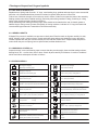
2.3 LEGEND SYMBOLS
TE27/32 4 SD
Smontaggio di sottogruppi
Sostituire con ogni montaggio
Disassembly of assembly groups
Renew at each reassembly
Montaggio di sottogruppi
Togliere - mettere la sicura
Reassemble to from assembly group
Unlock - lock e.g. split pin, locking plate, etc.
Smontaggio di particollari ingombranti
Mettere la sicura, incollare (mastice liquido)
Remove obstruction parts
Lock - adhere (liquid sealant)
Montaggio di particollari ingombranti
Evitare danni ai materiali, danni ai pezzi
Reinstall - remount parts which had obstructed disassembly
Guard against material damage, damage to parts
Attenzione, indicazione importante
Marchiari prima dello smontaggio (per il montaggio)
Attention! important notice
Mark before disassembly, observe marks when reasembl.
Controllare regolare p.e. coppie, misure, pressione etc.
Carricare riempire (olio - lubrificante)
Check - adjust e.g. torque, dimensions, pressures etc.
Filling - topping up - refilling e.g. oil, cooling water, etc.
T = Attrezzature speciali
P = Pagina
Scarricare olio, lubrificante
T = Special tool
P = Page
Drain off oil, lubricant
Rispettare direzione di montaggio
Tendere
Note direction of installation
Tighten - clamp ; tightening a clamping device
Controllare esaminare controllo visuale
Insere pressione nel circuito idraulico
Visual inspection
Apply pressure into hydraulic circuit
Eventualimente riutilizzable (sostituire se necessario)
Pulire
Possibly still serviceable, renew if necessary
To clean
03/2010
2-10
3 TECHNICAL SPECIFICATIONS
TE27/32 4 SD
03/2010
3-11
Technical specifications
SPICER OFF-HIGHWAY
TEN BRIELE 3
B-8200
BELGIUM
MODEL
SERIAL
3.1. IDENTIFICATION OF THE UNIT
1. Model and type of the unit
2. Serial number.
3.2. WEIGHT, DIMENSIONS, OIL CAPACITY
Weight (dry):
Max. Length:
Max. With:
Max. Heigth:
Oil capacity
60 liter [15.9 US Gallon] without cooler and hydraulic lines.
Consult Operator’s manual on applicable machine for system capacity.
TE27/32 4 SD
865 Kg [1903 lb]
1011 mm [39.8”]
703 mm [27.7”]
982 mm [38.7”]
03/2010
3-12
Technical specifications
3.3 TIGHTENING TORQUEs
3.3.1 Torque specifications for lubricated or plated screw threads
NOM. THD
SIZE
GRADE 5
FINE THREAD
TORQUE Lbs.ft [Nm]
GRADE 5
COARSE THREAD
TORQUE Lbs.ft [Nm]
.2500
.3125
.3750
9-11 [12.2-14.9]
16-20 [21.7-27.1]
26-29 [35.2-39.3]
8-10 [10.8-13.6]
12-16 [16.3-21.7]
23-25 [31.2-33.9]
.4375
.5000
.6525
.6250
41-45 [56-61]
64-70 [87-95]
91-100 [123-136]
128-141 [174-191]
37-41 [50.2-55.6]
57-63 [77-85]
82-90 [111-122]
113-124 [153-168]
.7500
Partnumber
prefix
223-245 [302-332]
200-220 [271-298]
2C
1C
NOM. THD
SIZE
GRADE 8
FINE THREAD
TORQUE Lbs.ft [Nm]
GRADE 8
COARSE THREAD
TORQUE Lbs.ft [Nm]
.2500
.3125
11-13 [14.9-17.6]
28-32 [38-43.4]
9-11 [12.2-14.9]
26-30 [35.2-40.7]
.3750
.4375
37-41 [50.2-55.6]
58-64 [79-87]
33-36 [44.7-48.8]
52-57 [70.5-77.3]
.5000
.6525
90-99 122-134]
128-141 [174-191]
80-88 [108-119]
115-127 [156-172]
.6250
.7500
Partnumber
prefix
180-198 [224-268]
315-347 [427-470]
159-175 [216-237]
282-310 [382-420]
18C-94G-96G
17C-93G-95G
TE27/32 4 SD
03/2010
3-13
Technical specifications
3.3.1 Torque specifications for lubricated or plated screw threads (continued)
NOM. THD SIZE
COARSE THREAD
GRADE 8.8
TORQUE Lbs.ft [Nm]
GRADE 10.9
TORQUE Lbs.ft [Nm]
GRADE 12.9
TORQUE Lbs.ft [Nm]
M5 x 0,8
M6 x 1
M8 x 1,25
M10 x 1,5
M12 x 1,75
M14 x 2
M16 x 2
M20 x 2,5
M24 x 3
M30 x 3,5
M36 x 4
3.7-4.4 [5-6]
5.9-7.4 [8-10]
14.8-18.4 [20-25]
29.5-36.9 [40-50]
50-55 [68-75]
81-92 [110-125]
125-140 [170-190]
236-266 [320-360]
420-479 [570-650]
5.2-5.9 [7-8]
8.9-11.1 [12-15]
22.1-25.8 [30-35]
44.3-47.9 [60-65]
74-81 [100-110]
111-129 [150-175]
177-203 [240-275]
332-369 [450-500]
590-664 [800-900]
5.9-7.4 [8-10]
9.6-11.8 [13-16]
25.8-29.5 [35-40]
47.9-55.3 [65-75]
85-96 [115-130]
133-155 [180-210]
207-236 [280-320]
387-443 [525-600]
664-774 [900-1050]
848-959 [1150-1300]
1475-1660 [2000-2250]
1180-1328 [1600-1800]
2028-2323 [2749-3149]
1364-1549 [1850-2100]
2397-2729 [3249-3699]
Partnumber prefix
1CM -1GM
7CM-10CM-4GM
3GM
NOM. THD SIZE
FINE THREAD
GRADE 8.8
TORQUE Lbs.ft [Nm]
GRADE 10.9
TORQUE Lbs.ft [Nm]
GRADE 12.9
TORQUE Lbs.ft [Nm]
M8 x 1
M10 x 1
M10 x 1,25
M12 x 1,25
M12 x 1,5
M14 x 1,5
M16 x 1,5
M18 x 1,5
M18 x 2
M20 x 1,5
M22 x 1,5
M24 x 1,5
M24 x 2
M27 x 1,5
17-20 [23-28]
35-42 [47-57]
32-40 [44-54]
60-68 [82-92]
58-65 [78-88]
94-105 [128-143]
159-169 [215-228]
221-236 [300-320]
207-221 [280-300]
302-332 [410-450]
413-443 [560-600]
531-590 [720-800]
509-568 [690-770]
789-848 [1070-1150]
25-28 [34-39]
52-60 [71-81]
49-57 [67-77]
89-96 [120-130]
86-94 [117-127]
142-153 [193-208]
216-227 [293-308]
319-330 [433-448]
304-315 [413-428]
439-476 [595-645]
586-623 [795-845]
767-841 [1040-1140]
730-804 [990-1090]
1129-1202 [1530-1630]
30-34 [41-46]
62-69 [84-94]
58-66 [79-89]
105-116 [143-158]
101-112 [138-153]
162-184 [220-250]
258-273 [350-370]
369-398 [500-540]
347-376 [470-510]
503-559 [683-758]
681-736 [923-998]
882-992 [1195-1345]
845-955 [1145-1295]
1308-1420 [1175-1925]
Partnumber prefix
TE27/32 4 SD
2CM -5GM
03/2010
3-14
Technical specifications
3.3.2 Elastic stop nut torque
THREAD SIZE
TORQUE
M10 x 1
6-7 [8-10]
M14 x 1.5
7-9 [10-12]
M18 x 1.5
M22 x 1.5
25-30 [34-41]
35-44 [48-60]
83-103 [112-140]
M33 x 2
3.3.3 Torque tables for plugs (“o”-ring ports)
THREAD SIZE
TORQUE Lbs.ft [Nm]
5/16-24
3/8-24
7/16-20
1/2-20
9/16-18
3/4-16
7/8-14
11/16-12
15/16-12
15/8-12
17/8-12
3-5 [4-7]
5-8 [7-11]
7-10 [9-14]
10-13 [14-18]
12-15[16-20]
20-25 [27-34]
30-35 [41-47]
45-50 [61-68]
65-75 [88-102]
75-85 [102-115]
Partnumber prefix
124K-47K
75-85 [102-115]
3.3.4 Torque tables for pipe plugs
THREAD SIZE
TORQUE Lbs.ft [Nm]
Partnumber prefix
1/16-27
1/8-27
1/4-18
3/8-18
1/2-14
3/4-10 or 14
1-11 1/2
5-7 [7-9]
7-10 [9-14]
15-20 [20-27]
25-30 [34-41]
30-35 [41-47]
40-45 [54-61]
50-55 [68-75]
16F-40K-41K-1
10F-16F-40K-41K-2
11F-16F-40K-41K-4
11F-16F-40K-41K-6
11F-16F-40K-41K-8
11F-16F-40K-41K-12
11F-16F-40K-41K-16
1 1/4-11 1/2
60-65 [81-88]
11F-16F-40K-41K-20
3.3.5 Permanent metric plug torque chart
Plugs (Permanent plugs)
Nominal Size
Torque Nm [Lbs.ft]
M18 x 1.5 6H
34-41
[25-30]
M26 x 1.5 6H
61-68
[45-50]
TE27/32 4 SD
03/2010
3-15
Technical specifications
3.4 PRESSURE & TEMPERATURE SPECIFICATIONS
•
Normal operating temperature 70 - 120°C [158 - 248F] measured at temperature check port to cooler
(port 71 or port 32 **).
•
Maximum allowed transmission temperature 120°C [248 F].
•
Transmission regulator pressure (*) - (neutral) - port 31 (**).
- at 600 RPM: 22.5 bar [326.3 PSI] minimum.
- at 2650 RPM: 25.5 bar [369.8 PSI] maximum.
•
Pump flow (*)
- System pump flow: 100.7 l/min minimum [26.60 GPM] at 2170 RPM.
- Lube pump flow: 52.4 l/min [13.84 GPM] minimum at 2170 RPM selective lube
84.6 l/min [22.35 GPM] maximum at 2910 RPM.
•
Clutch pressures (*)
- 1st clutch:
port 41 (**).
- 2nd clutch:
port 42 (**).
- 3rd clutch:
port 43 (**).
- 4th clutch:
port 44 (**).
- forward clutch: port 45 (**).
- reverse clutch: port 46 (**).
at 2200 RPM :
- 20.5bar [297.3PSI] minimum with 1st clutch activated.
•
Filter bypass valve set at 4.1 to 4.5 bar(*) [59.4 to 65.2 PSI].
•
Lube pressure (*) (port 34) - 4.0-5.5 bar [58 - 80 PSI] at 2200RPM.
•
Internal total leakage at 1000 engine RPM
Fwd/Rev: 4l/min. [1 GPM] maximum
1st:
9.2l/min [2.43 GPM] maximum
2nd-3rd-4th: 4l/min [1 GPM] maximum
Converter: 5-12 l/min [1.3-3.2 GPM] at 1000RPM
•
Safety valve : cracking pressure (*) 8.8-9.6 bar [127.6-139.2 PSI].
•
To cooler (converter out) pressure (*) (port 33) 5 bar [72.5PSI] min at 2000RPM engine speed
and a max of 8.5 bar [123.3 PSI] pressure at no load governed speed.
(*)
(**)
All pressures and flows to be measured with oil temperature of 82 - 93° C ( 180 - 200F).
Refer to section troubleshooting for check port identification.
TE27/32 4 SD
03/2010
3-16
Technical specifications
3.5 Electrical specifications
•
Proportional valves:
FWD/REV - 1st/3rd - 2nd/4th:
coil resistance : 7.25 Ω at 20°C [68°F].
•
Selection valves:
FWD/N/REV - 1st/3rd - 2nd/4th:
coil resistance : 12V - 7.1 Ω at 20°C [68°F].
coil resistance : 24V - 28.5 Ω at 20°C [68°F].
•
Speed sensor :
- type: magneto resistive sensor.
- sensing distance: 0 - 1,8 mm [0” - 0.07”].
- Sensor signal: generates a square current with a fixed amplitude changing between 7-14 mA.
•
Temp sensor:
-Material: silicon
-Resistance at 25°C [77°F] = 2000 Ω ± 1%
•
Pressure sensor:
-Supply voltage 4.5-5.5V
-Maximum current: 10mA
-Pressure range: 1 to 31 bar [14.5-450PSI]
-±1.2% full scale (31bar [450PSI]) range 1 to 25 bar [14.5-363 PSI]
-±2.5% full scale (31bar [450PSI]) range 25 to 31 bar [363-450PSI]
3.6 Hydraulic cooler lines specifications
•
•
•
•
Minimum 25.4mm [1”] internal diameter for lines and fittings.
Suitable for operation from ambient to 120° C [248° F] continuous operating temperature.
Must withstand 28 bar [406PSI] continuous pressure and with 41 bar [595PSI] intermittent surges.
Conform SAE J1019 and SAE J517,100RI
TE27/32 4 SD
03/2010
3-17
4 MAINTENANCE
T27/32 4 SD
03/2010
4-18
Maintenance
4.1. Oil specification
4.1.1 Recommended lubricants
•
Dexron* III, viscosity at 40° C [104° F]: 33 - 38 cSt
100° C [212° F]: 7 - 8 cSt
Sump preheaters
Preheat the transmission fluid to the mimimum temperature for the oil viscosity used before engine startup.
4.1.2 Normal oil change interval
Drain and refill system every 1000 hrs for average environmental and duty cycle conditions. Severe or sustained high operating temperature or very dusty atmospheric conditions will result in accelerated detioration or
contamination. Judgement must be used to determine the required change intervals for extreme conditions.
Drain and refill system as follows (drain with oil at 65 - 93° C [150 - 200 F°])
1. Drain transmission.
2.
Remove and discard filter. Install new filter.
3.
Refill transmission to FULL mark.
4.
Run engine at 500 - 600 RPM to prime convertor and lines.
5.
Recheck level with engine running at 500 - 600 RPM and add oil to bring level to LOW mark.
When oil temperature is hot 82.2 - 93.3 °C (180- 200 F) make final oil level check and adjust if necessary to bring oil level to FULL mark.
Note
It is recommended that oil filter be changed after 100 hours of operation on new, rebuilt or repaired unit.
EXTENDED OIL CHANGE INTERVAL
Extended oil service life may result when using synthetic fluids. Appropriate change intervals should be determined for each transmission by measuring oil oxidation and wear metals over time, to determine a baseline.
Wear metals analysis can provide useful inforamtion but a transmission should not be removed from service
based solely on this analysis.
filters
Service oil filter element intervals
100hrs first time
Then every 1000 hrs under normal envirronmental and duty cycle conditions.
4.2 MAINTENANCE INTERVALS
4.2.1 Daily
Check oil level daily with engine running at idle (600 RPM) and oil at 82 - 93 °C (180-200 F).
Maintain oil level at full mark.
4.2.2Clutch calibration
Every 2000hrs perform automatic clutch calibration
* DEXRON is a registered trademark of GENERAL MOTORS CORPORATION
T27/32 4 SD
03/2010
4-19
Maintenance
4.3 Servicing machine after components overhaul
The transmission, torque converter, and its allied hydraulic system are important links in the driveline between
the engine and the wheels. The proper operation of either unit depends greatly on the condition and operation
of the other. Therefore, whenever repair or overhaul of one unit is performed, the balance of the system must
be considered before the job can be considered complete.
After the overhauled or repaired transmission has been installed in the machine, the oil cooler, and connecting
hydraulic system must be thoroughly cleaned. This can be accomplished in several manners and a degree of
judgement must be exercised as to the method employed.
The following are considered the minimum steps to be taken:
1. Drain entire system thoroughly.
2.
3. Disconnect and clean all hydraulic lines. Where feasible hydraulic lines should be removed from machine for cleaning.
Replace oil filter element.
4.
The oil cooler must be thoroughly cleaned. The cooler should be “back flushed” with oil and compressed air until all foreign material has been removed. Flushing in direction of normal oil flow will not adequately clean the cooler. If necessary, cooler assembly should be removed from
machine for cleaning, using oil, compressed air, and steam cleaner for that purpose.
IMPORTANT
DO NOT use flushing compounds for cleaning purposes.
5.
Reassemble all components and use only type oil recommended from lubrication section.
Fill transmission through filler opening until fluid comes up to the oil level check port.
Run engine 2 minutes at 500+600 R.P.M. to prime torque converter and hydraulic lines.
Recheck level of fluid in transmission with engine running at idle (500-600 R.P.M.).
Add quantity necessary to bring fluid level to oil level check port.
Recheck with hot oil (180-200 F) 82-93° C.
6.
Recheck all drain plugs, lines, connections, etc., for leaks and tighten where necessary.
T27/32 4 SD
03/2010
4-20
Maintenance
4.4 Procedure for performing automatic calibration
4.4.1 Introduction
The APC200 firmware contains an automatic transmission calibration procedure, which is able to optimize the
shift quality of the transmission.
An automatic calibration has to be done:
- When the vehicle is build at the OEM
- Every 2000 hrs of transmission operation
- When an overhaul of the transmission is done
- When the transmission is repaired
- When the APC200 is replaced
4.4.2 running the automatic calibration
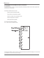
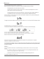
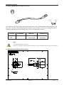
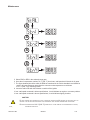
4.4.2.1 How to enter the calibration mode
S
S
M
S
S
M
M
M
M
M
M
M
The automatic calibration mode is entered by pressing the S-button on the APC200 <display for 15 seconds during POWER-UP of the APC200 (See above figure)
T27/32 4 SD
03/2010
4-21
Maintenance
4.4.3 PERFORMING AN AUTOMATIC CALIBRATION
Before the automatic calibration can be started, a number of conditions need to be fulfi lled :
- The parking brake on the vehicle has to be activated.
- The transmission temperature needs to be above 60° C. See the next paragraph how to use the
‘HEAT’-mode to do this in a time effective way.
- The engine speed has to be kept at around 800 rpm (± 200 rpm) during the complete calibration. If
the APC200 has control over the engine, the engine speed will be adapted automatically.
If all the conditions mentioned above are met, the actual automatic calibration can be performed starting from
the following display on the APC200 :
To trigger the automatic calibration procedure, push the S-button once. You will get this APC200-display readout:
The APC200 asks you to put the shift lever in FORWARD.
The automatic transmission calibration procedure starts. This is indicated on the APC200-display :
the fisrt 2 characters indicates which clutch is calibrated (clutch 1 to clutch 6)
the last 2 characters indicates the calibration phase inwhich this clutch is (mode 1 or mode2)
When all clutches have been calibrated, the APC200 displays :
At this point, the automatic calibration has completed successfully. The normal duration of a complete
transmission calibration is around 15 minutes.
To exit the automatic calibration mode, you should need to switch off the ignition key the vehicle. Make sure that
the APC200 has powered down – wait for 2 seconds. Now restart the vehicle and the new tuning results will be
activated automatically.
REMARK 1 :
If you get any different information on the APC200 display as described above, there can be two possible
reasons:
• the calibration conditions are not fulfi lled (temperature is too low, parking brake switched off, the
vehicle is moving, engine rpm is too high or too low)
• a calibration error has occurred during the calibration (message starting with an ‘E’).
For possible messages see chapter 4.4.5
T27/32 4 SD
03/2010
4-22
Maintenance
REMARK 2 :
By selecting REVERSE on the shift lever, while the automatic calibration is performing, the procedure will abort
the automatic calibration immediately and restart the APC200. You can use this as an emergency procedure
when something goes wrong during the calibration procedure.
Note : by aborting the automatic calibration, the calibration is not finalized and needs to be done from the
beginning.
4.4.4 HEATING UP THE TRANSMISSION BY USING THE ‘HEAT’-MODE
The ‘HEAT’-mode allows to select forward / reverse while the parking brake is activated, without forcing neutral
and will disable the inching and declutch function. During the heat mode the highest gear is forced – even when
the shift lever is in a lower gear. This combination allows the driver to heat up the transmission by going into
stall.
The paragraph how to enter the calibration mode (see 1st paragraph), also displays how the ‘HEAT’-mode can be
activated. Once you see on the display “tran”, you can press the M-button once to go into the “heat”-mode. The
APC200 will display :
To trigger the ‘HEAT’-mode, push the S-button. The APC200 will display the sump temperature :
This means the actual sump temperature of the transmission is 20°C.
T27/32 4 SD
03/2010
4-23
Maintenance
Perform the following steps in order to heat up the transmission :
1. Make sure the parking brake is active and works properly.
2. Put the transmission in forward by selecting forward with the shift lever and then accelerates the engine to full throttle.
3. Keep the engine at full throttle for about 15 seconds and then put the gearbox in neutral by selecting neutral with the shift lever. Keep the engine at full throttle!
4. Keep the gearbox in neutral at full engine throttle for about 15 seconds again.
5. Release the throttle pedal and decelerate the engine to idle.
6. Go back to point 2 and repeat until the APC200 display shows a temperature above 60°C. When the
temperature is above 60° C, the temperature indication on the display starts blinking. Now you can switch to the automatic calibration, by pressing the M-button for several times – until the APC200 displays “tran”.
FULL
IDLE
forward
neutral
15 Sec.
15 Sec.
REMARK :
During this warm up procedure, it is possible that the converter out temperature of the transmission exceeds the
maximum limit. This is a consequence of heating up the transmission using this quick procedure.
When this occurs, the engine speed will be limiting to half throttle when the APC200 has engine control or forcing
neutral when the APC200 has no engine control. To solve this, simply leave the transmission in neutral for a
minute and throttle the engine to around 1300 rpm. This will allow the heat in the converter to be evacuated.
After one or two minutes, you can resume the heating up procedure if the transmission temperature has not
reached 60 °C yet.
T27/32 4 SD
03/2010
4-24
Maintenance
4.4.5 CALIBRATION CONDITION MESSAGES AND CALIBRATION ERRORS
This chapter gives an overview of the most common calibration condition messages. Normally, you will be able
to repair the cause of a calibration condition message yourself. However, you will have to contact the OEM of the
machine when a calibration error appears.
4.4.5.1 Calibration condition messages
The APC200 expects the shift lever Put the shift jever back in NEUTRAL
to be in NEUTRAL, but finds it in
another position.
(FORWARD or REVERSE)
THE APC200 expects the partking
brake to be ON while it is OFF
Put the parking brake ON
The APC200 has detected output
speed
Verify that the parkiing brake is ON and working properly. If this is already the case, you will be obliged to
keep the machine at standstill by using the footbrake.
Once the machine has been stopped, the APC200
will ask the driver to shift to FORWARD before continuing the calibration.
Engine RPM is to low according
to the limit that is necessary for
calibration.
If the vehicle is equiped with throttle-by-wire, the
engine RPM will be automatically adapted. In the
other case, the driver has to change the throttle pedal
position until the display looks as follows:
Engine RPM is to high according
to the limit that is necessary for
calibration.
After being to low or to high, the
engine RPM is coming back into
the correct bounderies for calibration
When during the automatic transmission calibration the temperature
becomes to low, the APC200 display indicates the actual transmission temperature.
Use the M-button on the APC200 to go back to the
'HEAT' mode and the S-button to trigger this mode.
Now you have to warm-up the transmission again until the temperature is above 60° C [140° F]. Then go
back to the automatic tuning mode by the M-button
and trigger this one again to continue calibration.
4.4.5.2 Calibration errors
Calibration errors have the form ‘E1.xx’ or ‘E2.xx’ (example : E1.25). Please contact the OEM of the
machine if an error of this form appears on the display.
T27/32 4 SD
03/2010
4-25
4.4.6 PERFORMING A STALL TEST
With a stall test it is possible to test clutch pack slippage or test the converter/engine stall speed in each gear.
How to Preform a stall test
1 Activate parking brake
2 Activate calibration mode during power up and holding the S button for 15 seconds
3 select "STAL" using the M button
FULL
IDLE
forward
neutral
15 Sec.
15 Sec.
4 Select the requested range gear with the S button
S
ENGINE SPEED
S
ENGINE SPEED
S
ENGINE SPEED
S
ENGINE SPEED
T27/32 4 SD
5 Select FWD or REV in the selected range gear
6 request full throttle and read the engine speed at the APC display
7 All speeds should reach approximately the same value when the transmission in ok
8 Leave the stall mode with the M button or switch-off the ignition
03/2010
4-26
5 INSTALLATION DETAILS
TE27/32 4 SD
03/2010
5-27
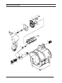
5 Installation details
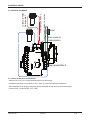
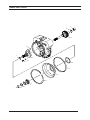
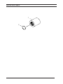
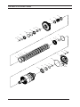
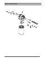
5.1 Converter drive coupling
Measure the “A” dimension (bolt circle diameter) and order drive plate kit listed below.
Note three (3) kits have two (2) intermediate drive plates and one (1) drive plate and weld nut assembly.
Three (3) kits with three intermediate drive plates.
(1) DRIVE PLATE AND
WELD NUT ASSEMBLY
A
A
BOLT CIRCLE DIA.
BACKING RING
BOLT CIRCLE DIA.
(2) INTERMEDIATE DRIVE PLATES
BACKING RING
(3) INTERMEDIATE DRIVE PLATES
“A” Dimension (Bolt circle diameter)
“A” Dimension (Bolt circle diameter)
• 15” (381.0 mm) diameter
• 15” (381.0 mm) diameter
• 16” (406.4 mm) diameter
• 16” (406.4 mm) diameter
• 17” (431.8 mm) diameter
• 17” (431.8 mm) diameter
Each kit will include the following parts:
• 2 Intermediate drive plates
• 1 Drive plate and weld nut assembly
• 1 Backing ring
• 6 Mounting screws
• 6 Lock washers
• 1 Instruction sheet
Each kit will include the following parts:
• 3 Intermediate drive plates
• 1 Backing ring
• 6 Mounting screws
• 6 Lock washers
• 1 Instruction sheet
Position drive plate and weld nut assembly on torque converter assembly with welded nuts toward converter.
Align intermediate drive plates and backing ring with holes in torque converter assembly.
Note:
Two dimples 180° apart in backing ring must be out (Toward the engine flywheel).
Install cap screws and washers. Tighten 40 - 50 Nm [30 to 37 lbft] torque.
TE27/32 4 SD
03/2010
5-28
Installation details
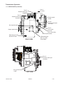
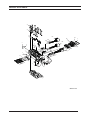
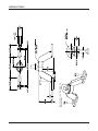
5.2 TRANSMISSION TO ENGINE INSTALLATION
PROCEDURE
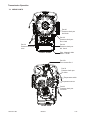
1. Remove all burrs from flywheel mounting face and nose
pilot bore. Clean drive plate surface with solvent.
2. Check engine flywheel & housing for conformance to
standard SAE No. 3 per SAE J927 and J1033 tolerance
specifications for pilot bore size, pilot bore runout and
mounting face flatness. Measure and record engine
crankshaft end play (Fig. 1).
3. Install two 63,50 mm (2.50”) long transmission to
flywheel housing guide studs in the engine flywheel
housing as shown. Rotate the engine flywheel to align a
drive plate mounting screw hole with the flywheel housing
access hole (Fig. 2).
*4. Install a 101,60 mm (4.00”) long drive plate locating
stud .3750-24 fine thread in a drive plate nut. Align the
locating stud in the drive plate with the flywheel drive plate
mounting screw hole positioned in step No. 3.
FLYWHEEL H OUSING
ENGINE
FLYWHEEL
PILOT BORE
FLYWHEEL
FIG. 1
CONVERTER HOUSING
FLYWHEEL HOUSING
4"STUD
5. Rotate the transmission torque converter to align the
locating stud in the drive plate with the flywheel drive plate
mounting screw hole positioned in step No. 3. Locate
transmission on flywheel housing.
Aligning drive plate to flywheel and transmission to
flywheel housing guide studs. Install transmission to
flywheel housing screws. Tighten screws to specified
torque. Remove transmission to engine guide studs.
Install remaining screws and tighten to specified torque.
MOUNT
DIAL INDICATOR
HERE
21/2"ALIGNING
STUDS
DRIVE
PLATE
FLYWHEEL
FIG. 2
*6. Remove drive plate locating stud.
SPECIAL STUD, WASHER AND
SELF LOCK NUT FURNISHED
BY ENGINE MANUFACTURER.
FLYWHEEL HOUSING
7. Install drive plate attaching screw and washer. Snug
screw but do not tighten. Some engine flywheel
housings have a hole located on the flywheel housing
circumference in line with the drive plate screw access
hole. A screwdriver or pry bar used to hold the drive
plate against the flywheel will facilitate installation of
the drive plate screws. Rotate the engine flywheel and
install the remaining seven (7) flywheel to drive plate
attaching screws. Snug screws but do not tighten.
After all eight (8) screws are installed.
Torque each one according to torque specifications. This
will require tightening each screw and rotating the engine
flywheel until the full amount of eight (8) screws have been
tightened to specified torque.
FLYWHEEL
IMPELLER
COVER
INTERMEDIATE
DRIVE PLATES
FIG. 3
FIG.4
PLATES TO BE INSTALLED
WITH CONCAVE SIDE
TOWARD ENGINE FLYWHEEL.
8. Measure engine crankshaft end play after transmission
has been completely installed on engine flywheel. This
value must be within 0,025 mm (0.001”) of the end play
recorded in step No. 2.
* Does not apply to units having 3 intermediate drive plates.
See Fig.4.
FIG. 5
TE27/32 4 SD
03/2010
5-29
Installation details
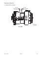
remote filter 2
from transmission to cooler
remote filter 1
from remote filter 1
to remote filter 1
from pump 1
5.3 External plumbing
cooler
from cooler to
transmission
from remote filter 2
5.3.1 Cooler & filter lines specifications
• Minimum 25.4 mm [1.0 inch] internal diameter for lines and fittings.
• Suitable for operation from ambient to 120° C [248° F] continuous operating temperature.
• Must withstand 30 bar [435psi] continuous pressure and with 40 bar [652 psi] intermittent surges.
• Conform SAE J1019 and SAE J517,100RI.
TE27/32 4 SD
03/2010
5-30
TE27/32 4 SD
03/2010
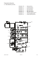
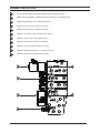
ASSY Partnr
4209752
4209752
4209750
4209751
TRANSMISSION
MODEL
TE27/32
INSTALL CLIP UNDER ANGLE X
(SEE TABLE)
AMP 2 Pins
AMP 2 Pins
AMP 2 pins
AMP 2 Pins
CONNECTOR
Engine Speed
Drum Speed
Output Speed
Turbine Speed
TYPE
180 Degrees
180 Degrees
180 Degrees
-90 Degrees
X POSITION
-
+
INSTALLATION INSTRUCTIONS
Installation details
5.4 speed sensor installation
5-31
Installation details
5.4 speed sensor installation (Continued)
Pin 2
Pin 1
The magneto resistive sensor generates a square wave current with a fixed amplitude changing between 7 mA
and 14 mA. The sensor has an integrated AMP superseal 2 pin connector. The two pins are numbered 1 and 2.
Following table shows the relation between wire colour, pin number and connection.
COLOUR
BROWN
BLUE
PIN NUMBER
FUNCTION
CONNECTION
1
2
Current input
Current output
Hot wire
Ground wire
Note
The sensor wires have a polarity.
Be sure to correctly observe sensor polarities, as wrong connections will deactivate the sensor !
5.5 Temperature sensor installation
TE27/32 4 SD
03/2010
5-32
6 TRANSMISSION OPERATION
TE27/32 4 SD
03/2010
6-33
6 Transmission Operation
6.1 The transmission assembly
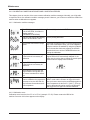
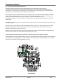
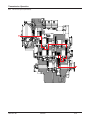
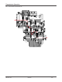
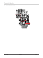
Basically the transmission is composed of five main assemblies:
1.
The converter, pump drive section and pressure regulating valve.
2.
The input shaft and directional clutches.
3.
The range clutches.
4.
The output section.
5.
The transmission control valve.
FWD
REV
3RD
2ND
1ST
4TH
The converter, pump drive section and pressure regulator valve
The input shaft and directional clutches
The range clutches
TE27/32 4 SD
The output section
03/2010
6-34
layout 32
Transmission Operation
6.1.1 The converter, pump drive section and pressure regulating valve
Engine power is transmitted from the engine flywheel to the impeller through the impeller cover.
This element is the pump portion of the hydraulic torque converter and is the primary component which starts
the oil flowing to the other components which results in torque multiplication. This element can be compared to a
centrifugal pump, that picks up fluid at its centre and discharges it at the outer diameter.
The torque converter turbine is mounted opposite the impeller and is connected to the turbine shaft of the torque
converter. This element receives fluid at its outer diameter and discharges it at its centre.
The reaction member of the torque converter is located between and at the centre of the inner diameters of the
impeller and turbine elements. Its function is to take the fluid which is exhausting from the inner portion of the
turbine and change its direction to allow correct entry for recirculation into the impeller element.
This recirculation will make the converter to multiply torque.
The torque multiplication is function of the blading (impeller, turbine and reaction member) and the converter output speed (turbine speed). The converter will multiply engine torque to its designed maximum multiplication ratio
when the turbine shaft is at zero RPM (stall).
Therefore we can say that as the turbine shaft is decreasing in speed, the torque multiplication is increasing.
The hydraulic pump is connected with the pump drive gear. This pump drive gear is driven by the impeller hub
gear. Since the impeller hub gear is connected with the impeller cover, the pump speed is in direct relation with
the engine speed.
FWD
REV
3RD
2ND
1ST
4TH
CONVERTER SECTION
CONTROL VALVE
left
TE27/32 4 SD
03/2010
6-35
Transmission Operation
6.1.2 The input shaft and directional clutches
The turbine shaft driven from the turbine transmits power to the directional clutches (fwd/rev.).
These clutches consist of a drum with internal splines and a bore to receive a hydraulic actuated piston.
The piston is oil tight by the use of sealing rings. The steel discs with internal splines, and friction discs with
external splines, are alternated until the required total is achieved.
A back-up plate is then inserted and secured with a retainer ring. A hub with outer diameter splines is inserted
into the splines of discs with teeth on the inner diameter. The discs and hub are free to increase in speed or
rotate in the opposite direction as long as no pressure is present in that specific clutch.
To engage the clutch, the solenoid will direct oil under pressure through tubes and passages to the selected
clutch shafts.
Oil sealing rings are located on the clutch shafts. These rings direct the oil through a drilled passage in the shaft
to the desired clutch.
Pressure of the oil forces the piston and discs against the back-up plate. The discs with splines on the outer
diameter clamping against discs with teeth on the inner diameter enables the drum and hub to be locked
together and allows them to drive as one unit.
When the clutch is released, a return spring will push the piston back and oil will drain back via the shift spool,
the bleed hole or holes in the clutch piston into the transmission sump.
These bleed holes will only allow quick escape of oil when the pressure to the piston is released.
The engagement of all range and directional clutches is modulated and electronically controlled. This means that
clutch pressure is built up gradually. This will enable the unit to make forward, reverse shifts while the vehicle is
still moving and will allow smooth engagement of drive.
3RD
FWD
REV
2ND
1ST
4TH
INPUT SECTION
TE27/32 4 SD
03/2010
6-36
Transmission Operation
6.1.3 The range clutches
Once a directional clutch is engaged power is transmitted to the range clutches.
Operation and actuation of the directional clutches is similar to the range clutches.
The engagement of the directional clutches is modulated.
For the 1st clutch assembly there is an extra bleed hole to allow full drain when the pressure
to the piston is released.
3RD
FWD
REV
1ST
2ND
4TH
RANGE CLUTCH6.1.4The output section
With a range clutch engaged, power is finally transmitted to the output shaft.
Output rotation is the opposite to input rotation when the forward clutch is engaged.
3RD
FWD
REV
2ND
1ST
4TH
OUTPUT SECTION
TE27/32 4 SD
03/2010
6-37
Transmission Operation
6.2 The transmission controls (refer to hydraulic diagram)
The transmission is controlled by a TCON ECU. This unit has a microprocessor that receives certain inputs (gear
selector position, speed senors,...), which are processed and will give output signals to the control valve.
Operation of the valve
Regulated pressure 22 - 26 bar [319 - 377 PSI] is directed to the proportional valve and selector valves to activate the clutches required.
When activated the proportional valve will give an output pressure curve from 0 to 26 bar [0-87PSI] proportional
to a current from 0 mA to 1000mA. Dampers are used to dampen any hydraulic vibration.
Directional selection
When a direction (forward or reverse) is selected, the required selector valve is activated for forward or
reverse and the proportional valve will provide a pressure rise from 0 to 26 bar feeding the directional clutch with
modulated pressure.
Range selection
When 1st clutch is selected, the 1st/3rd selector valve is actevated and the 1st/3rd proportional valve will provide
a pressure rise from 0 to 26 bar feeding the 1st clutch with modulated pressure.
When 2nd clutch is selected, the 2nd/4th selector valve is activated, the 1st/3rd proportional valve will decrease
pressure from 26 to 0 bar, thus releasing the 1st clutch in a controlled manner. At the same time the 2nd/4th proportional valve is activated and will provide a pressure curve from 0 to 26 bar, which will provide clutch overlap.
When the shift is finalized the 1st/3rd selector valve is deactivated.
When 3rd clutch is selected the 3rd/1st selector valve is not activated. The 2nd/4th proportional valve will
decrease pressure from 26 to 0 bar, thus releasing the 2nd clutch in a controlled manner. At the same time the
1st/3rd proportional valve is activated and will provide a pressure curve from 0 to 26 bar, which will provide
clutch overlap.
When the shift is finalized the 2nd/4th selector valve is deactivated.
When 4th clutch is selected, the 2nd/4th selector valve is not activated. The 1st/3rd proportional valve will
decrease pressure from 26 to 0 bar, thus releasing the 3rd clutch in a controlled manner. At the same time the
2nd/4th proportional valve is activated and will provide a pressure curve from 0 to 26 bar, which will provide
clutch overlap.
Restriction plug
The pressure line is connected to the drain line via a restricted hole. This ensures the drain line to remain air free
at all times and guarantees the reliable functioning of the proportional valves.
TE27/32 4 SD
03/2010
6-38
Transmission Operation
Pressure sensor
The control valve also has a pressure sensor installed to monitor overlap on range clutches
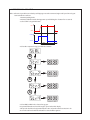
6.3 Electric solenoid controls
selected gear
Activated
Selector valve
Activated
Proportional valve
Activated
clutches
Forward 4
FWD
FWD/REV - 2nd/4th
Forward, 4th
Forward 3
FWD
FWD/REV -1st/3rd
Forward, 3rd
Forward 2
FWD - 2nd/4th
FWD/REV - 2nd/4th
Forward, 2nd
Forward 1
FWD - 1st/3rd
FWD/REV -1st/3rd
Forward, 1st
Neutral 4
2nd/4th
4th
Neutral 3
1st/3rd
3rd
Neutral 2
2nd/4th
2nd/4th
2nd
Neutral 1
1st/3rd
1st/3rd
1st
Reverse 4
REV
FWD/REV - 2nd/4th
Reverse, 4th
Reverse 3
REV
FWD/REV -1st/3rd
Reverse, 3nd
Reverse 2
REV - 2nd/4th
FWD/REV - 2nd/4th
Reverse, 2nd
Reverse 1
REV - 1st/3rd
FWD/REV -1st/3rd
Reverse, 1st
TE27/32 4 SD
03/2010
6-39
TE27/32 4 SD
03/2010
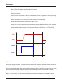
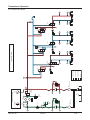
HOSE
HOSE
HOSE
35A
FILTER 2
34A
71
LUBRICATION
RANGE
CLUTCHES
TORQUE
CONVERTER
OIL SUMP
PUMP 2
52,4 L/min @ 2170 rpm
BY-PASS VALVE
4,1-4,5 bar
34
COOLER
HOSE
32
TEMPERATURE
GAUGE
AIR
BREATHER
SAFTY VALVE
CRACKING
9 bar
37
HOSE
34A
FILTER 1
31A
HOSE
PRESSURE
REGULATOR
VALVE 22 bar
PRESSURE
GAUGE
OPERATOR COMPARTMENT
SCREEN
PUMP 1
100,7 L/min @ 2170 rpm
BY-PASS VALVE
4,1-4,5 bar
31
41
Drain
High pressure
Low pressure
Lubrucation
FWD/REV
46
46
Ø0.9
FWD/N/REV
REV
CLUTCH
FWD
CLUTCH
Ø0.9
45
45
1ST/3RD
PRESSURE
SENSOR
41
41
Ø0.9
1ST/3RD
TE27/TE32 TRANSMISSION FULL FLOW VALVE - HYDRAULIC DIAGRAM
NEUTRAL SELECTED
1ST
CLUTCH
3RD
CLUTCH
Ø0.9
43
43
B PRESSURE INTENSIFIER 0-6 TO 0-20 bar
2ND/4TH
PRESSURE
SENSOR
A ELECTRONIC CONTROLLED MODULATION VALVE 6 TO 0 bar
42
42
Ø0.9
2ND/4TH
2ND
CLUTCH
Ø0.8
4TH
CLUTCH
Ø0.9
44
44
Transmission Operation
6.4 Powerflows, activated solenoids and hydraulic circuit
6.4.1 Neutral-1 Selected
6-40
Transmission Operation
6.4.1 Neutral-1 (Continued)
FWD
REV
3RD
2ND
1ST
4TH
TE27/32 4 SD
03/2010
6-41
TE27/32 4 SD
03/2010
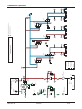
HOSE
HOSE
HOSE
35A
FILTER 2
34A
71
LUBRICATION
RANGE
CLUTCHES
TORQUE
CONVERTER
OIL SUMP
PUMP 2
52,4 L/min @ 2170 rpm
BY-PASS VALVE
4,1-4,5 bar
34
COOLER
HOSE
32
TEMPERATURE
GAUGE
AIR
BREATHER
SAFTY VALVE
CRACKING
9 bar
37
HOSE
34A
FILTER 1
31A
HOSE
PRESSURE
REGULATOR
VALVE 22 bar
PRESSURE
GAUGE
OPERATOR COMPARTMENT
SCREEN
PUMP 1
100,7 L/min @ 2170 rpm
BY-PASS VALVE
4,1-4,5 bar
31
41
6-42
Drain
High pressure
Low pressure
Lubrucation
FWD/REV
46
46
Ø0.9
FWD/N/REV
REV
CLUTCH
FWD
CLUTCH
Ø0.9
45
45
1ST/3RD
PRESSURE
SENSOR
41
41
Ø0.9
1ST/3RD
TE27/TE32 TRANSMISSION FULL FLOW VALVE - HYDRAULIC DIAGRAM
FORWARD FIRST SELECTED
1ST
CLUTCH
3RD
CLUTCH
Ø0.9
43
43
B PRESSURE INTENSIFIER 0-6 TO 0-20 bar
2ND/4TH
PRESSURE
SENSOR
A ELECTRONIC CONTROLLED MODULATION VALVE 6 TO 0 bar
42
42
Ø0.9
2ND/4TH
2ND
CLUTCH
Ø0.8
4TH
CLUTCH
Ø0.9
44
44
Transmission Operation
6.4.2 Forward 1st speed
Powerflow FWD 1st
Transmission Operation
6.4.2 Forward 1st speed (continued)
FWD
3RD
1ST
REV
2ND
4TH
TE27/32 4 SD
03/2010
6-43
TE27/32 4 SD
03/2010
HOSE
HOSE
HOSE
35A
FILTER 2
34A
71
LUBRICATION
RANGE
CLUTCHES
TORQUE
CONVERTER
OIL SUMP
PUMP 2
52,4 L/min @ 2170 rpm
BY-PASS VALVE
4,1-4,5 bar
34
COOLER
HOSE
32
TEMPERATURE
GAUGE
AIR
BREATHER
SAFTY VALVE
CRACKING
9 bar
37
HOSE
34A
FILTER 1
31A
HOSE
PRESSURE
REGULATOR
VALVE 22 bar
PRESSURE
GAUGE
OPERATOR COMPARTMENT
SCREEN
PUMP 1
100,7 L/min @ 2170 rpm
BY-PASS VALVE
4,1-4,5 bar
31
41
6-44
Drain
High pressure
Low pressure
Lubrucation
FWD/REV
46
46
Ø0.9
FWD/N/REV
REV
CLUTCH
FWD
CLUTCH
Ø0.9
45
45
1ST/3RD
PRESSURE
SENSOR
41
41
Ø0.9
1ST/3RD
TE27/TE32 TRANSMISSION FULL FLOW VALVE - HYDRAULIC DIAGRAM
FORWARD SECOND SELECTED
1ST
CLUTCH
3RD
CLUTCH
Ø0.9
43
43
2ND/4TH
PRESSURE
SENSOR
42
42
Ø0.9
2ND/4TH
2ND
CLUTCH
Ø0.8
4TH
CLUTCH
Ø0.9
44
44
Transmission Operation
6.4.3 Forward 2nd speed
Powerflow FWD 2nd
Transmission Operation
6.4.3 Forward 2nd speed (continued)
FWD
3RD
2ND
1ST
REV
4TH
TE27/32 4 SD
03/2010
6-45
TE27/32 4 SD
03/2010
HOSE
HOSE
HOSE
LUBRICATION
RANGE
CLUTCHES
OIL SUMP
PUMP 2
52,4 L/min @ 2170 rpm
BY-PASS VALVE
4,1-4,5 bar
34
COOLER
HOSE
TORQUE
CONVERTER
AIR
BREATHER
SAFTY VALVE
CRACKING
9 bar
37
HOSE
34A
FILTER 1
31A
HOSE
PRESSURE
REGULATOR
VALVE 22 bar
PRESSURE
GAUGE
SCREEN
PUMP 1
100,7 L/min @ 2170 rpm
BY-PASS VALVE
4,1-4,5 bar
31
41
6-46
Drain
High pressure
Low pressure
Lubrucation
FWD/REV
46
46
Ø0.9
FWD/N/REV
REV
CLUTCH
FWD
CLUTCH
Ø0.9
45
45
1ST/3RD
PRESSURE
SENSOR
41
41
Ø0.9
1ST/3RD
1ST
CLUTCH
3RD
CLUTCH
Ø0.9
43
43
B PRESSURE INTENSIFIER 0-6 TO 0-20 bar
2ND/4TH
PRESSURE
SENSOR
A ELECTRONIC CONTROLLED MODULATION VALVE 6 TO 0 bar
42
42
Ø0.9
2ND/4TH
2ND
CLUTCH
Ø0.8
4TH
CLUTCH
Ø0.9
44
44
6.4.4 Forward 3rd speed
35A
FILTER 2
34A
71
32
TEMPERATURE
GAUGE
OPERATOR COMPARTMENT
TE27/TE32 TRANSMISSION FULL FLOW VALVE - HYDRAULIC DIAGRAM
FORWARD 3rd SELECTED
Transmission Operation
Powerflow FWD 3rd
Transmission Operation
6.4.4 Forward 3rd speed (continued)
FWD
REV
3RD
2ND
1ST
4TH
TE27/32 4 SD
03/2010
6-47
TE27/32 4 SD
03/2010
HOSE
HOSE
HOSE
35A
FILTER 2
34A
71
LUBRICATION
RANGE
CLUTCHES
TORQUE
CONVERTER
OIL SUMP
PUMP 2
52,4 L/min @ 2170 rpm
BY-PASS VALVE
4,1-4,5 bar
34
COOLER
HOSE
32
TEMPERATURE
GAUGE
AIR
BREATHER
SAFTY VALVE
CRACKING
9 bar
37
HOSE
34A
FILTER 1
31A
HOSE
PRESSURE
REGULATOR
VALVE 22 bar
PRESSURE
GAUGE
OPERATOR COMPARTMENT
SCREEN
PUMP 1
100,7 L/min @ 2170 rpm
BY-PASS VALVE
4,1-4,5 bar
31
41
6-48
Drain
High pressure
Low pressure
Lubrucation
FWD/REV
46
46
Ø0.9
FWD/N/REV
REV
CLUTCH
FWD
CLUTCH
Ø0.9
45
45
1ST/3RD
PRESSURE
SENSOR
41
41
Ø0.9
1ST/3RD
TE27/TE32 TRANSMISSION FULL FLOW VALVE - HYDRAULIC DIAGRAM
FORWARD 4TH SELECTED
1ST
CLUTCH
3RD
CLUTCH
Ø0.9
43
43
2ND/4TH
PRESSURE
SENSOR
42
42
Ø0.9
2ND/4TH
2ND
CLUTCH
Ø0.8
4TH
CLUTCH
Ø0.9
44
44
Transmission Operation
6.4.5 Forward 4TH speed
Transmission Operation
6.4.5 Forward 4th speed (continued)
Powerflow FWD 4rd
FWD
REV
3RD
2ND
1ST
4TH
layout 32
TE27/32 4 SD
03/2010
6-49
TE27/32 4 SD
03/2010
HOSE
HOSE
HOSE
35A
FILTER 2
34A
71
LUBRICATION
RANGE
CLUTCHES
TORQUE
CONVERTER
OIL SUMP
PUMP 2
52,4 L/min @ 2170 rpm
BY-PASS VALVE
4,1-4,5 bar
34
COOLER
HOSE
32
TEMPERATURE
GAUGE
AIR
BREATHER
SAFTY VALVE
CRACKING
9 bar
37
HOSE
34A
FILTER 1
31A
HOSE
PRESSURE
REGULATOR
VALVE 22 bar
PRESSURE
GAUGE
OPERATOR COMPARTMENT
SCREEN
PUMP 1
100,7 L/min @ 2170 rpm
BY-PASS VALVE
4,1-4,5 bar
31
41
6-50
Drain
High pressure
Low pressure
Lubrucation
FWD/REV
46
46
Ø0.9
FWD/N/REV
REV
CLUTCH
FWD
CLUTCH
Ø0.9
45
45
1ST/3RD
PRESSURE
SENSOR
41
41
Ø0.9
1ST/3RD
TE27/TE32 TRANSMISSION FULL FLOW VALVE - HYDRAULIC DIAGRAM
REVERSE FIRST SELECTED
1ST
CLUTCH
3RD
CLUTCH
Ø0.9
43
43
B PRESSURE INTENSIFIER 0-6 TO 0-20 bar
2ND/4TH
PRESSURE
SENSOR
A ELECTRONIC CONTROLLED MODULATION VALVE 6 TO 0 bar
42
42
Ø0.9
2ND/4TH
2ND
CLUTCH
Ø0.8
4TH
CLUTCH
Ø0.9
44
44
Transmission Operation
.
Powerflow REV 1st
Transmission Operation
6.4.6 Reverse 1st speed
3RD
FWD
1ST
REV
2ND
4TH
TE27/32 4 SD
03/2010
6-51
TE27/32 4 SD
03/2010
HOSE
HOSE
HOSE
35A
FILTER 2
34A
71
LUBRICATION
RANGE
CLUTCHES
TORQUE
CONVERTER
OIL SUMP
PUMP 2
52,4 L/min @ 2170 rpm
BY-PASS VALVE
4,1-4,5 bar
34
COOLER
HOSE
32
TEMPERATURE
GAUGE
AIR
BREATHER
SAFTY VALVE
CRACKING
9 bar
37
HOSE
34A
FILTER 1
31A
HOSE
PRESSURE
REGULATOR
VALVE 22 bar
PRESSURE
GAUGE
OPERATOR COMPARTMENT
SCREEN
PUMP 1
100,7 L/min @ 2170 rpm
BY-PASS VALVE
4,1-4,5 bar
31
41
6-52
Drain
High pressure
Low pressure
Lubrucation
FWD/REV
46
46
Ø0.9
FWD/N/REV
REV
CLUTCH
FWD
CLUTCH
Ø0.9
45
45
1ST/3RD
PRESSURE
SENSOR
41
41
Ø0.9
1ST/3RD
TE27/TE32 TRANSMISSION FULL FLOW VALVE - HYDRAULIC DIAGRAM
REVERSE SECOND SELECTED
1ST
CLUTCH
3RD
CLUTCH
Ø0.9
43
43
2ND/4TH
PRESSURE
SENSOR
42
42
Ø0.9
2ND/4TH
2ND
CLUTCH
Ø0.8
4TH
CLUTCH
Ø0.9
44
44
Transmission Operation
6.4.7 Reverse 2nd speed
Transmission Operation
Powerflow REV 2nd
6.4.7 Reverse 2nd speed (continued)
3RD
FWD
REV
2ND
1ST
4TH
TE27/32 4 SD
03/2010
6-53
TE27/32 4 SD
03/2010
HOSE
HOSE
HOSE
35A
FILTER 2
34A
71
LUBRICATION
RANGE
CLUTCHES
TORQUE
CONVERTER
OIL SUMP
PUMP 2
52,4 L/min @ 2170 rpm
BY-PASS VALVE
4,1-4,5 bar
34
COOLER
HOSE
32
TEMPERATURE
GAUGE
AIR
BREATHER
SAFTY VALVE
CRACKING
9 bar
37
HOSE
34A
FILTER 1
31A
HOSE
PRESSURE
REGULATOR
VALVE 22 bar
PRESSURE
GAUGE
OPERATOR COMPARTMENT
SCREEN
PUMP 1
100,7 L/min @ 2170 rpm
BY-PASS VALVE
4,1-4,5 bar
31
41
6-54
Drain
High pressure
Low pressure
Lubrucation
FWD/REV
46
46
Ø0.9
FWD/N/REV
REV
CLUTCH
FWD
CLUTCH
Ø0.9
45
45
1ST/3RD
PRESSURE
SENSOR
41
41
Ø0.9
1ST/3RD
TE27/TE32 TRANSMISSION FULL FLOW VALVE - HYDRAULIC DIAGRAM
REVERSE 3rd SELECTED
1ST
CLUTCH
3RD
CLUTCH
Ø0.9
43
43
B PRESSURE INTENSIFIER 0-6 TO 0-20 bar
2ND/4TH
PRESSURE
SENSOR
A ELECTRONIC CONTROLLED MODULATION VALVE 6 TO 0 bar
42
42
Ø0.9
2ND/4TH
2ND
CLUTCH
Ø0.8
4TH
CLUTCH
Ø0.9
44
44
Transmission Operation
6.4.8 Reverse 3rd speed
Transmission Operation
Powerflow REV 3rd
6.4.8 Reverse 3rd speed (continued)
FWD
REV
3RD
2ND
1ST
4Th
TE27/32 4 SD
03/2010
6-55
TE27/32 4 SD
03/2010
HOSE
HOSE
HOSE
35A
FILTER 2
34A
71
LUBRICATION
RANGE
CLUTCHES
TORQUE
CONVERTER
OIL SUMP
PUMP 2
52,4 L/min @ 2170 rpm
BY-PASS VALVE
4,1-4,5 bar
34
COOLER
HOSE
32
TEMPERATURE
GAUGE
AIR
BREATHER
SAFTY VALVE
CRACKING
9 bar
37
HOSE
34A
FILTER 1
31A
HOSE
PRESSURE
REGULATOR
VALVE 22 bar
PRESSURE
GAUGE
OPERATOR COMPARTMENT
SCREEN
PUMP 1
100,7 L/min @ 2170 rpm
BY-PASS VALVE
4,1-4,5 bar
31
41
6-56
Drain
High pressure
Low pressure
Lubrucation
FWD/REV
46
46
Ø0.9
FWD/N/REV
REV
CLUTCH
FWD
CLUTCH
Ø0.9
45
45
1ST/3RD
PRESSURE
SENSOR
41
41
Ø0.9
1ST/3RD
TE27/TE32 TRANSMISSION FULL FLOW VALVE - HYDRAULIC DIAGRAM
REVERSE 4TH SELECTED
1ST
CLUTCH
3RD
CLUTCH
Ø0.9
43
43
2ND/4TH
PRESSURE
SENSOR
42
42
Ø0.9
2ND/4TH
2ND
CLUTCH
Ø0.8
4TH
CLUTCH
Ø0.9
44
44
Transmission Operation
6.4.9 Reverse 4TH speed
Powerflow REV 4rd
Transmission Operation
6.4.9 Reverse 4TH speed (continued)
FWD
REV
3RD
2ND
1ST
4Th
TE27/32 4 SD
03/2010
6-57
Transmission Operation
6.5 GEAR AND CLUTCH LAYOUT
ut
Inp
t
u
utp
O
TE27/32 4 SD
03/2010
6-58
TE27/32 4 SD
03/2010
7-59
7 Troubleshooting guide
The following information is presented as an aid to isolate and determine the specific problem area in a
transmission that is not functioning correctly.
When troubleshooting a “transmission” problem, it should be kept in mind that the transmission is only the
central unit of a group of related powertrain components. Proper operation of the transmission depends on the
condition and correct functioning of the other components of the group.
Therfore, to properly diagnose a suspected problem in the transmission, it is necessary to consider the
transmission fluid, charging pump, torque converter, transmission assembly, oil cooler, filter, connecting lines
and controls, including the engine as a complete system.
By analysing the principles of operation together with the information in this section, it should be possible to
identify and correct any malfunction which may occur in the system.
7.1 The Transmission
TE27/32 powershift transmission with torque converter troubles fall into four general categories:
1. Mechanical problems
2. Hydraulical problems
3. Electrical problems
4. Controller problems
In addition to the mechanical and electrical components, all of which must be in proper condition and functioning
correctly, the correct functioning of the hydraulic circuit is most important. Transmission fluid is the “life blood”
of the transmission. It must be supplied in an adequate quantity and delivered to the system at the correct
pressures to ensure converter operation, to engage and hold the clutches from slipping, and to cool and
lubricate the working components.
7.2 The input shaft and directional clutches
7.2.1 PERFORMING A STALL TEST
A stall test identifies transmission, converter or engine problems.
Use the following procedure:
With a stall test it is possible to test clutch packslippage or test the converter/engine stall speed in each gear.
How to perform the stall test
1 Put the vehicle against a solid barrier, such as a wall and/or apply the parking brake, block the wheels.
2 Activate calibration mode during power up end holding the S button for 15 seconds
3 Select "STAL" using the M buttom
Full
Idle
forward
neutral
15 Sec
TE27/32 4 SD
03/2010
15 Sec
7-60
Maintenance
S
ENGINE SPEED
S
ENGINE SPEED
S
ENGINE SPEED
S
ENGINE SPEED
5 Select FWD or REV in the selected range gear
6 Once the oil temperature reaches 70° C [158° F] check max. stall speed at full throttle in all gears.
7 The figure obtained should be within 50 RPM as mentioned in the vehicle handbook and should be equal in all gears. Between gears allow the converter outlet temperature to cool down
to 70° C [158° F] by selecting neutral.
8 Leave the stall mode with the M button or switch-off the ignition
If max. stall speed measured is below specifications, it could indicate an engine or converter problem.
If max. stall speed measured is above specifications, it could indicate slipping clutches.
CAUTION
Do not operate the converter at stall condition longer than 30 seconds at one time, shift to neutral for 15 seconds and repeat the procedure until desired temperature is reached.
Excessive temperature 120° C [250° F] maximum will cause damage to transmission clutches,
fluid, converter and seals.
TE27/32 4 SD
03/2010
7-61
Transmission Operation
7.2.2 Transmission pressure checks
Transmission problems can be isolated by the use of pressure tests. When the stall test indicates slipping
clutches, then measure clutch pack pressure to determine if the slippage is due to low pressure or clutch
plate friction material failure.
In addition, converter charging pressure and transmission lubrication pressure can also be measured.
7.2.3 Mechanical and electrical checks
Prior to checking any part of the system for hydraulic function (pressure testing), the following mechanical
and electrical checks should be made:
• Check the parking brake and inching pedal for correct adjustment.
• Be sure all lever linkage is properly connected and adjusted in each segment and at all connecting points.
• The controls are actuated electrically. Check the wiring and electrical components.
• Be sure that all components of the cooling system are in good condition and operating correctly.
The radiator must be clean to maintain proper cooling and operating temperatures for the engine and
transmission. Air clean the radiator, if necessary.
7.2.4 Hydraulic checks
Also, before checking the transmission clutches, torque converter, charging pump and hydraulic circuit for
pressure and rate of flow, it is imporatant to make the following transmission fluid check:
• Check oil level in the transmission. The transmission fluid must be at the correct (full level).
• All clutches and the converter and its fluid circuit lines must be fully charged (filled) at all times.
Note:
the transmission fluid must be at operating temperature of
Do not attempt to make these checks with cold oil.
obtain correct fluid level and pressure readings.
82 - 93° C [180 - 200° F] to To raise the oil temperature to this specification it is necessary to either operate (work) the vehicle or run
the engine with converter at “stall” (refer to 6.2.1 “stall test”).
Caution:
Be carefull that the vehicle does not move unexpectedly when operating the engine and converter at stall RPM.
7.2.5 Controller (APC200): Please refer to functional description
TE27/32 4 SD
03/2010
7-62
Transmission Operation
7.3 TROUBLESHOOTING GUIDE
Refer to the following troubleshooting guide for the diagnosis of typical transmission troubles
7.3.1 Low clutch pressure
Cause
Remedy
1. Low oil level.
2. Clutch pressure regulating valve stuck open.
3. Faulty charging pump.
4. Broken or worn clutch shaft or piston sealing rings.
1. Fill to proper level.
2. Clean valve spool and housing.
3. Replace pump.
4. Replace sealing rings.
7.3.2 Low charging pump output flow
Cause
Remedy
1. Low oil level.
2. Suction screen clogged.
3. Defective charging pump.
1. Fill to proper oil level.
2. Clean suction screen.
3. Replace charging pump.
7.3.3 Overheating
Cause
Remedy
1. Worn oil sealing rings
1. Remove, disassemble and rebuild converter assy.
2. Worn charging pump.
2. Replace charging pump.
3. Low oil level.
3. Fill to proper level.
4. Dirty oil cooler.
4. Clean cooler.
5. Restriction in cooler lines.
5. Change cooler lines.
7.3.4 Noisy converter
Cause
1. Worn charging pump.
2. Worn or damaged bearings.
Remedy
1. Replace charging pump.
2. A complete disassembly will be necassary to determine which bearing is faulty.
7.3.5 Lack of power
Cause
1. Low engine RPM at converter stall.
2. See “Overheating” and make same checks.
TE27/32 4 SD
03/2010
Remedy
1. Tune engine, check governor.
2. Make corrections as explained in “Overheating”.
7-63
Transmission Operation
7.4 CHECK POINTS
Port 42
Pressure check port
2nd clutch
Port 46
Pressure check port
Rev. clutch
Port 34
Pressure check port
Lube
Port 44
Pressure check port
4th. clutch
FRONT VIEW
Plug - Magnetic drain
M22 x 1.5 UNI
Port 16b
From remote filter 1
Port 32
Pressure check port
To cooler
Temperature switch
Temperature sensor
Port 43
Pressure check port
3rd clutch
REAR VIEW
TE27/32 4 SD
03/2010
7-64
Transmission Operation
7.4 CHECK POINTS (continued)
Port 11
To cooler
Port 31
Pressure check port
Regulator
Port 37
Pressure check port
Convertor in
Engine speed
sensor
Port 45
Pressure check port
Fwd clutch
Drum speed sensor
Port 12
From cooler
Output speed sensor
Port 16A
From remote filter
Turbine speed sensor
Metric flange for dipstick dia 25.4mm
4 Mounting holes
M20 x 2.5 THD
30mm DEEP
RIGHT VIEW
right
Port 41
Pressure check port
1st clutch
{
Oil level check port
¼ NPT
TE27/32 4 SD
LEFT VIEW
03/2010
7-65
left
Transmission Operation
7.4 CHECK POINTS (continued)
Port 13a
To remote filter
from pump 1
Port 13b
To remote filter
from pump 2
Oil fill hole
¾-14NPTF
TOP VIEW
top
TE27/32 4 SD
03/2010
7-66
Transmission Operation
7.4 CHECK POINTS (continued)
Checkpoint
Checkpoint
Checkpoint
Checkpoint
Checkpoint
Checkpoint
Checkpoint
Checkpoint
Checkpoint
Checkpoint
31A.............. System pressure
41................ 1st clutch pressure
42................ 2nd clutch pressure
43................ 3rd clutch pressure
44................ 4th clutch pressure
45................ FWD clutch pressure
46................ REV clutch pressure
66................ FWD/REV regulated pressure
67................ 1st/3rd regulated pressure
68................ 2nd/4th requlated pressure
31A
45
66
46
68
43
67
44
41
42
TE27/32 4 SD
03/2010
7-67
Transmission Operation
7.5 SPEED SENSOR - STATIC STANDALONE TEST
In order to be able to sense the currents, a series resistor of e.g. 200 Ω must be used. This resistor is integrated
in the controller, but when the sensor is to be used, it must be connected externally.
The idea is to connect the sensor to an external power source and measure the DC voltage across the series
resistor.
The voltage reading should be either 1.2V (from the 7mA ± 1mA current level) or 2.6 - 3.0V (for the 14mA ± 1mA
current level).
If the teeth can be moved slowly, distinct toggling between the two levels should be noticed.
TE27/32 4 SD
03/2010
7-68
Transmission Operation
7.6 Full flow valve components
FWD/REV
SELECTOR
VALVE
A
FWD/REV
PROPORTIONAL
VALVE
2ND/4TH
PROPORTIONAL
VALVE
3RD/1ST
PROPORTIONAL
VALVE
1ST/3RD
SELECTOR
VALVE
4TH/2ND
SELECTOR
VALVE
4TH/2ND
PRESSURE
SENSOR
3RD/1ST
PRESSURE
SENSOR
TE27/32 4 SD
03/2010
7-69
8 SECTIONAL VIEWS & PARTS IDENTIFICATION
TE27/32 4SD
03/2010
8-70
TORQUE CONVERTER GROUP
TE32
CONVERTER HOUSING GROUP
13
6
7
8
38 37
32
30
33
29
42
43
34
40
35
31
41
21
14
1
15
42
43
40
36
38
11
35 13
22
23
37
12
45
9
6
10
20
19
19
20
44
21
3
39
39
10
11
18
18
16
7
12 9
18
17
3
41
19
3
41
8
40
27
25
26
5
4
43
42
27
28
24
TE27/32 4 SD
03/2010
GRP-32011 rev.092002
8-71
TORQUE CONVERTER GROUP
Item
1
2
3
4
5
6
7
8
9
10
11
12
13
14
15
16
17
18
19
20
21
22
23
24
25
26
27
28
29
30
31
32
33
34
35
36
37
38
39
40
41
42
43
44
45
Description
Qty
Torque Converter...................................................................................................................... 1
Not Illustrated............................................................................................................................ 1
Plug - Expansion...................................................................................................................... 3
Plug ......................................................................................................................................... 1
“O” Ring.................................................................................................................................... 1
Tube.......................................................................................................................................... 1
Tube.......................................................................................................................................... 1
Tube.......................................................................................................................................... 1
Clip............................................................................................................................................ 2
“O” Ring.................................................................................................................................... 2
Capscrew.................................................................................................................................. 2
Lockwasher............................................................................................................................... 2
Tube.......................................................................................................................................... 1
Sleeve....................................................................................................................................... 1
Sleeve....................................................................................................................................... 1
Sleeve....................................................................................................................................... 1
Sleeve....................................................................................................................................... 1
Washer..................................................................................................................................... 3
Capscreww............................................................................................................................... 3
Lockwasher............................................................................................................................... 3
Plug........................................................................................................................................... 1
Plug........................................................................................................................................... 2
“O” Ring.................................................................................................................................... 2
Pin - Dowel............................................................................................................................... 2
Capscrew................................................................................................................................ 14
Capscrew.................................................................................................................................. 9
Lockwasher............................................................................................................................. 23
gasket - Converter to transmission case.................................................................................. 1
Bushing..................................................................................................................................... 1
Breather - Air............................................................................................................................. 1
Plug........................................................................................................................................... 1
Switch - Temperature................................................................................................................ 1
Adaptor - Temperature switch................................................................................................... 1
Sensor - Speed......................................................................................................................... 1
“O” Ring.................................................................................................................................... 1
Sensor - Speed 60mm.............................................................................................................. 1
Support - Speed sensor............................................................................................................ 2
Capscrew.................................................................................................................................. 2
Plug........................................................................................................................................... 2
Cover - Split flange................................................................................................................... 3
“O” ring...................................................................................................................................... 3
Capscrew................................................................................................................................ 12
Lockwasher............................................................................................................................. 12
Plug........................................................................................................................................... 1
“O” Ring.................................................................................................................................... 1
TE27/32 4 SD
03/2010
8-72
TRANSMISSION CASE & REAR COVER GROUPTE32
TRANSMISSION CASE GROUP
10
12
8
22
11
12
8
23
24
25
27
21 20
9
18
6
5
19
28
W
34
21
16
20
17
Y
32
33
5
6
6
5
5
6
14
W
31
6
5
X
35
29
26
29
W
X
Y
6
Y
1
4
5
15
3
W
2
X
Y
X
GRP-32021 rev. 092002
TE27/32 4 SD
03/2010
8-73
30
TRANSMISSION CASE & REAR COVER GROUP
Item
1
2
3
4
5
6
7
8
9
10
11
12
13
14
15
16
17
18
19
20
21
22
23
24
25
26
27
28
29
30
31
32
33
34
35
Description
Qty
Case - Transmission................................................................................................................. 1
Tube - 1st speed clutch pressure............................................................................................. 1
Tube - Low shaft rear bearing lube........................................................................................... 1
Tube - 3rd speed clutch pressure............................................................................................. 1
Sleeve - Pressure & lubr tube................................................................................................... 1
“O” ring...................................................................................................................................... 6
Cover - Rear............................................................................................................................. 1
Plug - Expansion...................................................................................................................... 1
Pin - Dowel............................................................................................................................... 2
Capscrew................................................................................................................................ 37
Capscrew.................................................................................................................................. 7
Lockwasher............................................................................................................................. 44
Gasket - Rear cover to transmission case................................................................................ 1
Plug........................................................................................................................................... 2
Plug - Magnetic drain................................................................................................................ 1
Sensor - Speed assy................................................................................................................ 1
“O” ring...................................................................................................................................... 1
Sensor - Speed assy................................................................................................................ 1
‘O” ring...................................................................................................................................... 1
Support - Speed sensor............................................................................................................ 2
Capscrew.................................................................................................................................. 2
Tube - Suction.......................................................................................................................... 1
“O” ring...................................................................................................................................... 1
Lockwasher............................................................................................................................... 2
Capscrew.................................................................................................................................. 2
Baffle - Oil................................................................................................................................. 1
Cover - Oil baffle....................................................................................................................... 1
Tube - Oil baffle........................................................................................................................ 3
Lockwasher............................................................................................................................... 6
Capscrew.................................................................................................................................. 3
Screw........................................................................................................................................ 3
Cover - Split flange................................................................................................................... 1
“O” ring...................................................................................................................................... 1
Capscrew.................................................................................................................................. 4
Lockwasher............................................................................................................................... 4
TE27/32 4 SD
03/2010
8-74
TURBINE SHAFT GROUP
TE32
TURbINE SHAFT GROUP
2
15
16
14
9
6
7
8
11
12
10
13
3
1
4
5
GRP-TE32031 rev 230902
TE27/32 4 SD
03/2010
8-75
TURBINE SHAFT GROUP
Item
1
2
3
4
5
6
7
8
9
10
11
12
13
14
15
16
Description
Qty
Bearing - Turbine shaft front..................................................................................................... 1
Bearing - Turbine shaft rear...................................................................................................... 1
Spacer - Front bearing.............................................................................................................. 1
Snapring................................................................................................................................... 1
Ring - Piston............................................................................................................................. 1
Stator support assy................................................................................................................... 1
Screw - Stator support.............................................................................................................. 7
Lockwasher............................................................................................................................... 7
Ring - Piston............................................................................................................................. 1
Baffle - Oil................................................................................................................................. 1
Seal - Oil baffle......................................................................................................................... 1
Ring - Oil baffle seal................................................................................................................. 1
Ring - Oil baffle retaining.......................................................................................................... 1
“O” Ring.................................................................................................................................... 1
Snapring................................................................................................................................... 1
Turbine shaft............................................................................................................................. 1
TE27/32 4 SD
03/2010
8-76
TE32
PUMP DRIVE GROUP
PUMP DRIVE GROUP
2
4
3
9
7
1
8
7
1
10
5
8
11
6
12
7
1
9
8
GRP-TE32051 rev 290802
TE27/32 4 SD
03/2010
8-77
PUMP DRIVE GROUP
Item
1
2
3
4
5
6
7
8
9
10
11
12
Description
Qty
Support - Pump drive bearing................................................................................................... 3
Screw - Bearing support........................................................................................................... 4
“O” Ring.................................................................................................................................... 4
Washer..................................................................................................................................... 4
Lockwasher............................................................................................................................... 2
Screw - Bearing support........................................................................................................... 2
Bearing - Pump drive gear........................................................................................................ 3
Snapring................................................................................................................................... 3
Gear - Aux. pump drive............................................................................................................. 2
Gear - Charging pump.............................................................................................................. 1
Gear - Impeller hub................................................................................................................... 1
Snapring................................................................................................................................... 1
TE27/32 4 SD
03/2010
8-78
Adaptor sleeve group
1
2
GRP-TE32201 rev.290502
TE27/32 4 SD
03/2010
8-79
Adaptor sleeve group
Item
1
2
Description
Qty
Sleeve - Pump drive................................................................................................................. 1
Snapring................................................................................................................................... 1
TE27/32 4 SD
03/2010
8-80
Wheel group
16
17
10
15
14
18
3
6
19
1
2
8
9
5
4
11
20
21
7
24
23
22
12
13
25
GRP-32061 rev.092002
TE27/32 4 SD
03/2010
8-81
Wheel group
Item
1
2
3
4
5
6
7
8
9
10
11
12
13
14
15
16
17
18
19
20
21
22
23
24
25
Description
Qty
Member - Reaction................................................................................................................... 1
Snapring................................................................................................................................... 1
Spacer - Reaction member....................................................................................................... 1
Turbine...................................................................................................................................... 1
Hub - Turbine............................................................................................................................ 1
Snapring................................................................................................................................... 1
Snapring................................................................................................................................... 1
Screw - Turbine hub............................................................................................................... 10
Locktab..................................................................................................................................... 5
Impeller..................................................................................................................................... 1
“O” Ring.................................................................................................................................... 1
Screw...................................................................................................................................... 32
Lockwasher............................................................................................................................. 32
Hub - Impeller........................................................................................................................... 1
“O” Ring.................................................................................................................................... 1
Screw........................................................................................................................................ 8
Ring - Impeller hub dcrew backing........................................................................................... 1
Bearing..................................................................................................................................... 1
Snapring................................................................................................................................... 1
Cover - Impeller........................................................................................................................ 1
Bearing - Turbine hub............................................................................................................... 1
“O” Ring.................................................................................................................................... 1
Spacer...................................................................................................................................... 1
Snapring................................................................................................................................... 1
Hub - Impeller cover................................................................................................................. 1
TE27/32 4 SD
03/2010
8-82
VARIOUS MODELS
FLEx PLATE GROUP
FLEX PLATE group
1
2
3
4
GRP-T40041 rev290802
TE27/32 4 SD
03/2010
8-83
DRIVE PLATE group
Item
1
2
3
4
Description
Qty
Assembly - Drive plate and (when used) welded nuts.............................................................. 1
Plate - Drive.............................................................................................................................. 5
Ring - Backing.......................................................................................................................... 1
Capscrew................................................................................................................................ 14
TE27/32 4 SD
03/2010
8-84
TE32
FWD & REV/2nd and 3th orFWD,
4thREV/2nd
clutch
shaft
assy SHAFT ASSY GROUP
& 3rd
or 4th CLUTCH
1
d
V
RE
&
2n
D
FW
2
3
th
d
3r
4
or
gRP-TE32071 (rev 15nov02)
TE27/32 4 SD
03/2010
8-85
FWD & REV/2nd and 3th or 4th clutch shaft assy
Item
1
2
3
3
Description
Qty
Fwd shaft drum assy................................................................................................................. 1
Rev/2nd shaft drum assy.......................................................................................................... 1
3rd shaft drum assy on 3 speed............................................................................................... 1
4th shaft drum shaft assy on 4 speed....................................................................................... 1
TE27/32 4 SD
03/2010
8-86
forward clutch shaft GROUP
TE32
FORWARD CLUTCH SHAFT GROUP
12
10
24
14
24
16
13
15
17
2
18
18
1
5
4
3
6
7
8
9
22
21
20
19
23
25
GRP-TE32091 rev240902
TE27/32 4 SD
03/2010
8-87
forward clutch shaft GROUP
Item
1
2
3
4
5
6
7
8
9
10
11
12
13
14
15
16
17
18
19
20
21
22
23
Description
Qty
Piston........................................................................................................................................ 1
Seal - Piston outer.................................................................................................................... 1
Seal - Piston inner.................................................................................................................... 1
Screen (not sold seperate........................................................................................................ 1
Disc - Clutch inner...................................................................................................................11
Disc - Clutch outer...................................................................................................................11
Plate - End................................................................................................................................ 1
Seal ......................................................................................................................................... 1
Snapring................................................................................................................................... 1
Washer - Belleville.................................................................................................................. 15
Ring - Retaining........................................................................................................................ 1
Spacer - Clutch piston.............................................................................................................. 1
Bearing - Clutch driven gear..................................................................................................... 1
Bearing..................................................................................................................................... 1
Bearing..................................................................................................................................... 1
Ring - Retaining........................................................................................................................ 1
Ring - Piston............................................................................................................................. 2
Ring - Retaining........................................................................................................................ 2
Bearing..................................................................................................................................... 1
Spacer...................................................................................................................................... 1
Snapring................................................................................................................................... 1
Retainer - Oil............................................................................................................................. 1
Snapring................................................................................................................................... 1
TE27/32 4 SD
03/2010
8-88
TE32
3rd speed clucth shaft GROUP
3RD SPEED CLUTCH SHAFT GROUP
12
10
11
14
16
13
17
2
15
19
18
4
3
1
28
6
8
7
5
27
21
9
24
23
22
20
19
29
26
25
GRP-TE32101 rev290802
TE27/32 4 SD
03/2010
8-89
3rd speed clucth shaft GROUP
Item
1
2
3
4
5
6
7
8
9
10
11
12
13
14
15
16
17
18
19
20
21
22
23
24
25
26
27
28
29
Description
Qty
Piston........................................................................................................................................ 1
Seal - Piston outer.................................................................................................................... 1
Seal - Piston inner.................................................................................................................... 1
Screen (not sold seperate)....................................................................................................... 1
Disc - Clutch inner...................................................................................................................11
Disc - Clutch outer...................................................................................................................11
Disc - Clutch outer half............................................................................................................. 2
Plate - End................................................................................................................................ 1
Snapring................................................................................................................................... 1
Washer - Belleville.................................................................................................................. 15
Spacer - Clutch piston.............................................................................................................. 1
Retainer - Spring...................................................................................................................... 1
Ring - Retainer.......................................................................................................................... 1
Bearing..................................................................................................................................... 1
Bearing..................................................................................................................................... 1
Washer..................................................................................................................................... 1
Snapring................................................................................................................................... 2
Snapring................................................................................................................................... 1
Ring - Piston............................................................................................................................. 2
Bearing..................................................................................................................................... 1
Cap - 3rd speed shaft rear bearing........................................................................................... 1
Spacer...................................................................................................................................... 1
Snapring................................................................................................................................... 1
“O” Ring.................................................................................................................................... 1
Plug........................................................................................................................................... 1
“O” Ring.................................................................................................................................... 1
Capscrew.................................................................................................................................. 4
Lockwasher............................................................................................................................... 4
“O” RIng.................................................................................................................................... 1
TE27/32 4 SD
03/2010
8-90
3rd speed gear
1
2
GRP-TE32111 rev290802
TE27/32 4 SD
03/2010
8-91
3rd speed gear
Item
1
2
Description
Qty
Gear - 3rd speed...................................................................................................................... 1
Gear - 3rd speed driven............................................................................................................ 1
TE27/32 4 SD
03/2010
8-92
REV / 2nd schaft GROUP
TE32
REV/2ND CLUTCH SHAFT GROUP
25
26
24
31
30
27
28
29
36
17
18
19
20
21
1
4
2
37
3
D
V
RE
N
&2
13
38
15 14
12
23
32
22
11
33
34
35
10
16
9
8
7
5
6
GRP-TE32121 rev. 240902
TE27/32 4 SD
03/2010
8-93
REV / 2nd schaft GROUP
Item
1
2
3
4
5
6
7
8
9
10
11
12
13
14
15
16
17
18
19
20
21
22
23
24
25
26
27
28
29
30
31
32
33
34
35
36
Description
Qty
Piston........................................................................................................................................ 1
Seal - Clutch piston outer......................................................................................................... 1
Seal - Clutch piston inner......................................................................................................... 1
Screen (Not Sold Separate)..................................................................................................... 1
Washer - Belleville.................................................................................................................... 7
Spacer - Clutch piston.............................................................................................................. 1
Ring - Retaining........................................................................................................................ 1
Disc - Clutch inner.................................................................................................................... 7
Disc - Clutch outer.................................................................................................................... 7
Plate - End................................................................................................................................ 1
Snapring................................................................................................................................... 1
Piston........................................................................................................................................ 1
Seal - Clutch piston outer......................................................................................................... 1
Seal - Clutch piston inner......................................................................................................... 1
Screen (Not Sold Separate)..................................................................................................... 1
Ring - Retaining........................................................................................................................ 1
Disc - Clutch inner...................................................................................................................11
Disc - Clutch outer...................................................................................................................11
Plate - End................................................................................................................................ 1
Seal........................................................................................................................................... 1
Snapring................................................................................................................................... 1
Washer - Bellevile................................................................................................................... 15
Spacer - Clutch piston.............................................................................................................. 1
Bearing..................................................................................................................................... 1
Bearing..................................................................................................................................... 1
Ring - Retaining........................................................................................................................ 1
Ring - Retaining........................................................................................................................ 1
Bearing..................................................................................................................................... 1
Ring - Retaining........................................................................................................................ 1
Ring.......................................................................................................................................... 1
Washer - Bearing thrust............................................................................................................ 1
Hub - 2nd Clutch disc............................................................................................................... 1
Snapring................................................................................................................................... 1
Retainer.................................................................................................................................... 1
Snapring................................................................................................................................... 1
Ring - Piston............................................................................................................................. 3
TE27/32 4 SD
03/2010
8-94
1st speed clutch shaft GROUP
TE32
1ST SPEED CLUTCH SHAFT GROUP
1
2
4
3
15
8
27
7
26
25
16
28
6
11
5
12
9
10
24
23
21
22
17
31
30
32
19
18
20
29
13
14
GRP-TE32131 rev290802
TE27/32 4 SD
03/2010
8-95
1st speed clutch shaft GROUP
Item
1
2
3
4
5
6
7
8
9
10
11
12
13
14
15
16
17
18
19
20
21
22
23
24
25
26
27
28
29
30
31
32
Description
Qty
Piston........................................................................................................................................ 1
Seal - Piston outer.................................................................................................................... 1
Seal - Piston inner.................................................................................................................... 1
Screen (not sold seperate)....................................................................................................... 1
Disc - Clutch inner...................................................................................................................11
Disc - Clutch outer...................................................................................................................11
Plate - End................................................................................................................................ 1
Snapring................................................................................................................................... 1
Washer - Belleville.................................................................................................................... 9
Spacer - Clutch piston.............................................................................................................. 1
Retainer - Spring...................................................................................................................... 1
Ring - Retainer.......................................................................................................................... 1
Bearing..................................................................................................................................... 1
Washer..................................................................................................................................... 1
Bearing..................................................................................................................................... 1
Retainer - Oil............................................................................................................................. 1
Ring - Piston............................................................................................................................. 2
Cap - Bearing........................................................................................................................... 1
“O” Ring.................................................................................................................................... 2
Plug........................................................................................................................................... 2
“O” Ring.................................................................................................................................... 2
“O” Ring.................................................................................................................................... 1
Capscrew.................................................................................................................................. 4
Lockwasher............................................................................................................................... 4
Bearing..................................................................................................................................... 1
Spacer - Bearing....................................................................................................................... 1
Snapring................................................................................................................................... 1
Snapring................................................................................................................................... 1
Bearing..................................................................................................................................... 1
Bearing..................................................................................................................................... 1
Spring - Disc............................................................................................................................. 1
Nut............................................................................................................................................ 1
TE27/32 4 SD
03/2010
8-96
4th speed clutch shaft GROUP
TE32
4TH SPEED CLUTCH SHAFT GROUP
1
4
2
3
15
17
14
16
19
11
13
18
12
9
10
8
6
7
5
6
GRP-TE32141 rev 290802
TE27/32 4 SD
03/2010
8-97
4th speed clutch shaft GROUP
Item
1
2
3
4
5
6
7
8
9
10
11
12
13
14
15
16
17
18
19
Description
Qty
Piston........................................................................................................................................ 1
Seal - Piston outer.................................................................................................................... 1
Seal - Piston inner.................................................................................................................... 1
Screen (not sold seperate)....................................................................................................... 1
Disc - Clutch inner...................................................................................................................11
Disc - Clutch outer half............................................................................................................. 2
Disc - Clutch outer...................................................................................................................11
Plate - End................................................................................................................................ 1
Snapring................................................................................................................................... 1
Spacer - Clutch piston.............................................................................................................. 1
Retainer - Spring...................................................................................................................... 1
Spring....................................................................................................................................... 1
Ring - Retainer.......................................................................................................................... 1
Bearing..................................................................................................................................... 1
Snapring................................................................................................................................... 1
Snapring................................................................................................................................... 1
Hub........................................................................................................................................... 1
Snapring................................................................................................................................... 1
Ring - Piston............................................................................................................................. 2
TE27/32 4 SD
03/2010
8-98
1st shaft gear GROUP
TE32
1ST SHAFT AND GEAR GROUP
2
1
t
1s
GRP-TE32151 rev. 290502
TE27/32 4 SD
03/2010
8-99
1st shaft gear GROUP
Item
1
2
Description
Qty
Gear - Idler................................................................................................................................ 1
Assy - 1st speed clutch............................................................................................................. 1
TE27/32 4 SD
03/2010
8-100
TE32
OUTPUT SHAFT GROUP
Output shaft GROUP
1
5
5
3
19
4
6
18
17
20
16
8
14
13
10
11
9
12
15
7
2
GRP-TE32161 rev.290502
TE27/32 4 SD
03/2010
8-101
output shaft group
Item
1
2
3
4
5
6
7
8
9
10
11
12
13
14
15
16
17
18
19
20
Description
Qty
Shaft - Output........................................................................................................................... 1
Bearing..................................................................................................................................... 1
Bearing..................................................................................................................................... 1
Retainer - Oil............................................................................................................................. 1
Snapring................................................................................................................................... 1
Snapring................................................................................................................................... 1
“O” Ring.................................................................................................................................... 1
Seal - Output oil........................................................................................................................ 1
Cap - Bearing........................................................................................................................... 1
Plug........................................................................................................................................... 1
“O” Ring.................................................................................................................................... 1
Stud.......................................................................................................................................... 4
Lockwasher............................................................................................................................... 4
Nut............................................................................................................................................ 4
“O” Ring.................................................................................................................................... 1
Bearing..................................................................................................................................... 1
“O” Ring.................................................................................................................................... 1
Washer - Flange....................................................................................................................... 1
Locknut..................................................................................................................................... 1
Flange....................................................................................................................................... 1
TE27/32 4 SD
03/2010
8-102
Regulator valve group
TE32
REGULATOR VALVE GROUP
16
15
19
18
14
17
2
3
1
5
6
4
7
9
13
12
11
12
8
10
GRP-TE32171 rev. 240902
TE27/32 4 SD
03/2010
8-103
Regulator valve group
Item
1
2
3
4
5
6
7
8
9
10
11
12
13
14
15
16
17
18
19
Description
Qty
Assy - Valve regulator............................................................................................................... 1
Gasket - Valve to converter housing......................................................................................... 1
“O” Ring.................................................................................................................................... 1
Pump - Hydraulic...................................................................................................................... 1
Shaft - Gear to pump................................................................................................................ 1
Snapring................................................................................................................................... 1
Screw........................................................................................................................................ 2
Adaptor - Suction tube side...................................................................................................... 1
Adaptor - Suction transmission case side................................................................................ 1
Capscrew.................................................................................................................................. 8
Hose - Suction.......................................................................................................................... 1
Clamp - suction......................................................................................................................... 2
“O” Ring.................................................................................................................................... 2
Screw........................................................................................................................................ 8
Lockwasher............................................................................................................................... 8
Cap - Flange............................................................................................................................. 1
“O” Ring.................................................................................................................................... 1
Capscrew.................................................................................................................................. 4
Lockwasher............................................................................................................................... 4
TE27/32 4 SD
03/2010
8-104
control valve GROUP
TE32
GROUP-CONTROL VALVE
31
30
28
29
15A
6B
6A
16
1817
19
2
9
15B
2
25
6C
8
2
1
7
10
2
2
21
20A
14
13
12 11
20B
4
20C
23
24
2
4
22
5
27
3
26
32
GRPTE32184
TE27/32 4 SD
03/2010
8-105
control valve GROUP
Item
1
2
3
4
5
6A
6B
6C
7
8
9
10
11
12
13
14
15A
15B
16
17
18
19
20A
20B
20C
21
22
23
24
25
26
27
28
29
30
31
32
Description
Qty
control valve housing................................................................................................................ 1
Plug-expansion....................................................................................................................... 22
Plug-expansion......................................................................................................................... 3
Plug - Restriction...................................................................................................................... 4
Plug - orifice.............................................................................................................................. 1
Proportional valve forward/reverse........................................................................................... 1
Proportional valve 2nd/4th........................................................................................................ 1
Propottional valve 3rd/1st......................................................................................................... 1
O-ring........................................................................................................................................ 3
O-ring........................................................................................................................................ 6
Capscrew.................................................................................................................................. 6
Selector valve forward/reverse................................................................................................. 1
O-ring........................................................................................................................................ 1
O-ring........................................................................................................................................ 1
O-ring........................................................................................................................................ 1
O-ring........................................................................................................................................ 1
Selector valve 1st/3rd............................................................................................................... 1
Selector valve 4th/2nd.............................................................................................................. 1
O-ring........................................................................................................................................ 2
O-ring........................................................................................................................................ 2
O-ring........................................................................................................................................ 2
O-ring........................................................................................................................................ 2
accumulator spool forward/reverse.......................................................................................... 1
accumulator spool 2nd/4th ...................................................................................................... 1
accumulator spool 3rd/1st ....................................................................................................... 1
Pin-accumulator stop................................................................................................................ 3
Spring....................................................................................................................................... 3
Plug........................................................................................................................................... 3
O-ring........................................................................................................................................ 3
Sensor-valve pressure.............................................................................................................. 2
Plug........................................................................................................................................... 2
O-ring........................................................................................................................................ 2
Plug......................................................................................................................................... 10
O-ring...................................................................................................................................... 10
Lockwasher............................................................................................................................. 16
Capscrew................................................................................................................................ 16
Gasket...................................................................................................................................... 1
TE27/32 4 SD
03/2010
8-106
remote filter adapter GROUP
13
TE32
REMOTE FILTER ADAPTOR GROUP
11
4
14
12
9
10
3
5
8
4
7
6
2
10
9
11
14
12
13
1
GRP-TE32191 rev.290502
TE27/32 4 SD
03/2010
8-107
remote filter adaptor GROUP
Item
1
2
3
4
5
6
7
8
9
10
11
12
13
14
Description
Qty
Filter.......................................................................................................................................... 1
Adapter - Filter.......................................................................................................................... 1
Assy - Filter adapter body......................................................................................................... 1
Plug........................................................................................................................................... 1
Spool - Safety valve.................................................................................................................. 1
Plug........................................................................................................................................... 1
“O” Ring.................................................................................................................................... 1
Spring....................................................................................................................................... 1
Plug........................................................................................................................................... 2
“O” Ring.................................................................................................................................... 2
Cap - Flange............................................................................................................................. 2
“O” Ring.................................................................................................................................... 2
Capscrew.................................................................................................................................. 8
Lockwasher............................................................................................................................... 8
Note: 2 sets required
TE27/32 4 SD
03/2010
8-108
9 assembly instructions
TE27/32 4SD
03/2010
9-109
9 assembly instructions
1
10
8
6
2
3
4
3RD
FWD
2
11
3
REV
2ND
1ST
5
12
4TH
7
TE27/32 4 SD
9
03/2010
layout 32 9-110
assembly instructions
All lead-in chamfers for oil seals, pistonrings and 0-rings must be smooth and free from burrs. Inspect at assembly.
Add some grease to 0-rings before assembly.
Add some grease to piston rings before assembly.
Apply a thin coating of grease between seal lips on lip type seals prior to assembly.
Use only precoated pipe plugs. On uncoated pipe plugs apply a light coat of Loctite© 592
Pump must be filled up with oil prior to assembly.
After assembly of parts using Loctite© there must not be any free or excess material which might enter the oil
circuit.
1
Apply a light coat of Loctite© 262 or 270 to all thru hole stud holes.
2
Teflon seals must be sized prior to assembly. Add some grease to seal diameter of clutch hub before assembly.
3
Fwd and Rev Clutch
TE32
11 seperator plates with outer splines.
11 friction plates (friction material on both sides) with inner splines
Clearance
TE27
Min
Max
6.0mm [0.23in]
6.4mm [0.25in]
8 seperator plates with outer splines.
8 friction plates (friction material on both sides) with inner splines.
Clearance
Min
6.0mm [0.23in]
Max 6.4mm [0.25in]
Choose an end plate with suitable thickness to obtain this clearance.
Caution
The seperator plates for Fwd and Rev and 1st and 2nd are not the same.
DO NOT MIX PLATES WITH PLATES FROM OTHER CLUTCHES.
4
1st Clutch
TE32
11 seperator plates with outer splines.
11 friction plates (friction material on both sides) with inner splines
Clearance
TE27
Min
Max
4.35mm [0.17in]
4.75mm [0.19in]
10 seperator plates with outer splines.
10 friction plates (friction material on both sides) with inner splines.
Clearance
Min
4.35mm [0.17in]
Max 4.75mm [0.19in]
Choose an end plate with suitable thickness to obtain this clearance.
TE27/32 4 SD
03/2010
9-111
ASSEMBLY INSTRUCTIONS
5
2nd Clutch
TE32
7 seperator plates with outer splines.
7 friction plates (friction material on both sides) with inner splines
Clearance
TE27
Min
Max
2.75mm [0.10in]
3.15mm [0.12in]
6 seperator plates with outer splines.
6 friction plates (friction material on both sides) with inner splines.
Clearance
Min
2.75mm [0.10in]
Max 3.15mm [0.12in]
Choose an end plate with suitable thickness to obtain this clearance.
6
3rd Clutch
TE32
12 seperator plates with inner splines.
11 friction plates (friction material on both sides) with outer splines
2 1-sided friction plates (friction material on one (1) side) with outer splines.
Clearance
TE27
Min
Max
3.5mm [0.14in]
3.9mm [0.16in]
9 seperator plates with inner splines.
8 friction plates (friction material on both sides) with outer splines.
2 1-sided friction plates (friction material on one (1) side) with outer splines.
Clearance
Min
3.5mm [0.14in]
Max 3.9mm [0.16in]
Choose an end plate with suitable thickness to obtain this clearance.
7
4th Clutch
TE32
11 seperator plates with inner splines.
10 friction plates (friction material on both sides) with outer splines
2 1-sided friction plates (friction material on one (1) side) with outer splines.
Clearance
TE27
Min
Max
3.1mm [0.12in]
3.5mm [0.14in]
11 seperator plates with inner splines.
10 friction plates (friction material on both sides) with outer splines.
2 1-sided friction plates (friction material on one (1) side) with outer splines.
Clearance
Min
3.1mm [0.12in]
Max 3.5mm [0.14in]
Choose an end plate with suitable thickness to obtain this clearance.
TE27/32 4 SD
03/2010
9-112
ASSEMBLY INSTRUCTIONS
8
Be sure that shielded and sealed bearings are mounted as shown.
9
Seals must be pressed in perpendicular upon shaft axis from bearing side.
10
Tighten air breather to 31-41 Nm [25-30 Lbs.ft]
11
Tighten nut to 145-160 Nm [107-118 Lbs.ft]
12
Tighten nut to 339-407 Nm [250-300 Lbs.ft]
13
Tighten 2 coil nuts to 6.8-9.5 Nm [250-300 Lbs.ft]
14
Tighten 1 valve to 53-73 Nm [39-54 Lbs.ft]
15
Tighten 6 screws to 5-6 Nm [3.7-4.4 Lbs.ft]
16
Tighten 2 coil nuts to 6.8-9.5 Nm [5-7 Lbs.ft]
17
Tighten 2 pressure sensors to 7-11 Nm [5-8 Lbs.ft]
18
Tighten 2 valves to 34-36 Nm [25-27 Lbs.ft]
13
14
15
18
16
17
TE27/32 4 SD
03/2010
9-113
ASSEMBLY INSTRUCTIONS
INSTALLATION INSTRUCTIONS FOR TE27/32 VALVE
Remove the valve
Refer to “Cleaning & Inspection” pages. The area around the valve must be clean and free of any foreign
material.
Unscrew 16 bolts (marked with hexagonals on the drawing) some turns. When all bolts are loose, you should
be able to move the valve. Replace 2 bolts by aligning studs. Remove the remaining 14 hex bolts and valve
from the transmission case.
Install the valve
Install 2 aligning studs. install new gasket and valve body.
Install 14 bolts and handtighten according to the number sequence on the drawing, replace the studs by bolts.
Now torque all bolts twice to 20-25 Nm [15-18Lbs.ft] in the correct sequence.
Recalibrate the transmission.
16
15
13
14
2
1
3
4
5
7
6
10
8
12
TE27/32 4 SD
03/2010
9
11
9-114
ASSEMBLY INSTRUCTIONS
TE27/32 4 SD
03/2010
9-115
11 SPECIAL TOOLS
TE27/32 4 SD
05/2004
11-190
11 SPECIAL TOOLS
TE27/32 4 SD
05/2004
11-191
SPECIAL TOOLS
Bolt M10 x 40
TE27/32 4 SD
05/2004
Eyebolt M16
11-192
Bolt .4375-14 UNC-3B X 20
both sides
SPECIAL TOOLS
TE27/32 4 SD
05/2004
11-193
SPECIAL TOOLS
TYP
TYP
TE27/32 4 SD
05/2004
11-194
APPLICATION POLICY
Capability ratings, features and specifications vary depending upon the model type of service. Applications approvals must
be obtained from Spicer Off-Highway Products Division. We reserve the right to change or modify our product specifications,
configurations, or dimensions at any time without notice.
SPICER OFF-HIGHWAY PRODUCTS
Ten Briele 3
B-8200 Sint-Michiels
Brugge, Belgium