1
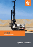
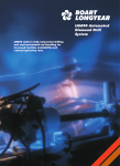
LF™ DRILLS
Commissioning Checklist
© Copyright 2012 Boart Longyear. All rights reserved.
LF™ DRILLS CHECK LIST
Commissioning Procedure
Ensure you have a copy of the sales order with you to review content with the customer
(no pricing to be listed on your copy) prior to starting the commissioning process.
Commissioning Process
o
Drilling Safety
Refer to the Drilling Safety guide in front of the parts book.
Train drill crew in safe drilling procedures and practices.
Ensure that all safety guards are left installed on the equipment, the site is keep clean with no
tripping hazards, train in rod handling, fuel storage etc.
ADVISE OPERATOR
NEVER:
–travel up or down with the feed carriage when the head has been opened
–use the leveling jacks to pull stuck rods
–store the overshot inside the mast behind the feed cylinder
Upon receipt of the drill the first thing to do is visually inspect the rig for any obvious damage
or oil leaks that may have occurred during shipping. With the customer present inspect all
items received. Using the packing lists check off all items and quantities received. Note any
shipping errors.
o
Drill Introduction
Discuss drill depth capacities, power unit HP/ KW rating, torque ratings etc. Describe the drill
components, weights etc. Cover all tech data information with the customer and drill crew.
(Refer to the tech data in the operation and service manual)
Copyright © 2012 Boart Longyear. All rights reserved.
o
Drill Inspection
(continued on following page)
2
LF™ DRILLS CHECK LIST (continued)
o
Operation, Engine Maintenance, Hydraulic System Maintenance, etc.
(Refer to the operation and service manual)
Using the table of contents as a guide read and discuss all sections of this manual with the
drill crew.
o
Ordering Parts
Review the parts book with the customer discuss drill warranty, part numbering system, how
to locate items in the parts book, procedure for ordering parts etc.
o
Drill Setup & Anchoring
Ensure that the drill is properly anchored before the drilling operation begins.
[Refer to the anchoring procedure in the operation and service manual (if published)]
o
Drill Startup
Prior to starting the engine, ensure that all shut off valves on the suction lines are tagged in the
open position.
–Check the hydraulic reservoir oil level
–Check the engine oil level.
–Check the coolant level in the radiator.
–Check the oil level in the W-11 pump
–Check the main winch oil level
–Check the battery water level in each cell
Copyright © 2012 Boart Longyear. All rights reserved.
–Check the oil level in the PQ rotation unit and four speed transmission after raising the mast
to the vertical position
3
–Check all the fastening hardware on the drill mast, base frame, power unit etc. to ensure that
they have not become loose in shipment.
o
Drilling Operations
Before the drilling starts, allow the driller to operate the drill to become familiar with the
directional controls, speeds of functions, etc.
Train driller in chuck jaw installation, foot clamp slip installation, etc.
Explain how to determine the bit weight pressure (review chart in Operations Manual).
o
Corebarrel and Diamond Products Training
Refer to the coring catalogue to train the drill crew in core barrel and diamond product
selection, use and maintenance.
(It is a good idea to leave a copy of the coring catalogue with the customer.)
Train in core barrel options such as landing indicator, water retention, types of bits and casing
shoes etc.
Copyright © 2012 Boart Longyear. All rights reserved.
(continued on following page)
4
LF™ DRILLS CHECK LIST (continued)
o
Service Tools Required for Commissioning
Basic hand mechanics hand tool kit, hydraulic test gauges with connecting hoses, hydraulic flow
meter, digital tachometer, infrared temperature sensor. Also an assortment of JIC test fittings,
tees, etc. (supplied with tool kit).
Train customer in use of these tools.
Copyright © 2012 Boart Longyear. All rights reserved.
Note:
Explain to the customer that the drill has been fully tested at the factory using calibrated tools
and instruments before shipping. The testing documents are available on request.
5
o
PQ Drill Head
Review the separate drill head and chuck assembly instructions in the operation and service
manual the customer’s mechanic and drill crew.
Demonstrate how to change the chuck jaws and bushings and how to identify proper jaw and
bushing sizes by part number.
Refer to the hydraulic schematic and the hydraulic adjustment procedures to train the customer
on the hydraulic system explaining the flow path from pumps, valves etc.
o
Primary Hydraulic System Explanation/Pressure Settings
The primary pump sends oil thru the high pressure filter to the load sensing main valve
bank. The pump compensator is set at 4500 PSI, load sensing standby pressure is
300 PSI. The main valve controls oil to the rotation circuit, fast feed circuit, main hoist
and wire line hoist circuit.
The main relief valve in the main valve bank is set at 4800 PSI. This relief adjustment is
factory set and should not be tampered with. The load sense relief valve for the fast feed is
fixed at 3000 PSI for A & B ports. The wire line winch load sense relief is fixed @ 2500 PSI
for A & B ports. These valves are internal in the work sections and factory set. Oil returns
from the main valve to the return manifold, then to the oil cooler, then to the main return filter
to the reservoir.
o
Secondary Hydraulic System
Oil from the secondary pump is sent to the water pump flow control valve in the control
panel. Oil from the flow control valve is sent to the water pump hydraulic motor. Return
oil from the water pump hydraulic motor passes thru the main return filter to the hydraulic
reservoir. Since the secondary pump is load sensing the water pump flow and pressure can
be regulated by turning this control valve. Pump compensator pressure setting is 3,000 PSI
and load sensing standby pressure is 300 PSI. The case drain oil is sent to the case drain
return manifold, then to hydraulic reservoir.
Copyright © 2012 Boart Longyear. All rights reserved.
(continued on following page)
6
LF™ DRILLS CHECK LIST (continued)
o
Auxiliary Hydraulic System
The secondary pump sends oil to the secondary manifold for the chuck, rotation speed control,
rod clamp, fine feed, rod making / breaking, mud mixer, head side shift and set up valve (all
hydraulic rams). The secondary pump compensator pressure is 2000 PSI.
Pressure adjustments on the secondary valves are as follows:
–PQ Chuck - 1400 PSI
–Rod Clamp - 750 to 850 PSI
–Mud Mixer Sequence Valve - 1900 PSI
Oil returns from the auxiliary manifold to the return manifold, to the return filter to the reservoir.
Oil from the auxiliary pump case drain is sent to the case drain return manifold and then to the
reservoir.
o
Main Winch Brake Release Valve
The main line brake is released electronically, when the fine feed valve is actuated in “the down”
feed position.
o
Rod Handling
To prevent damage to the spragg clutch in the main line winch it is important to instruct the driller
to properly tension the hoisting cable before opening the chuck. If the rods are allowed to drop
against the hoist cable each time the chuck is opened the resulting shock load may prematurely
damage the spragg bearing in the main line winch.
o
PQ Rotation Unit
Copyright © 2012 Boart Longyear. All rights reserved.
Review the separate drill head and chuck assembly instructions in the operation and service
manual with the customer’s mechanic and drill crew
Particular attention should be made to first checking the oil level in the PQ head when the mast
is in the vertical position as per the operation and service manual. Once the mast is set at the
required drilling angle the level should be noted. The rotation unit’s lube system is controlled by
a pump/motor combination, which run on separate hydraulic circuits.
The motor operates off the auxiliary circuit @ 2000PSI. It drives the lube pump.
The pump is protected by a suction filter, metered oil on the pump’s outlet at 2 ½ GPM is
controlled by a PCFC (pressure compensated flow control) valve, through a flow meter and
then into an oil cooler. Leaving the cooler oil returns to the head box to be re-circulated by the
lube pump.
(continued on following page)
7
o
PQ Chuck
All grease fittings on the chuck should be lubricated daily. The fittings that lubricate the chuck
jaw ramps must be lubricated when the chuck is in the open position.
Demonstrate how to change the chuck jaws and bushings and how to identify proper jaw and
bushing sizes by part number
o
Drill Maintenance
Follow recommended service intervals and oil specifications in the operation and service
manual. For information on the power unit servicing refer to the power unit maintenance
manual.
o
Complete and Submit Warranty Registration Check List
Fill out the form on the following page and send to Boart Longyear for warranty consideration.
Copyright © 2012 Boart Longyear. All rights reserved.
Copyright © 2012 Boart Longyear. All rights reserved.
warranty registration CHECK LIST
Once the drill commissioning has been completed fill out the warranty registration check list below. Fold in half, seal,
add correct postage and mail to Boart Longyear, fax to 385-234-3095 or scan and email to [email protected].
Warranty registration must be completed and on file to obtain warranty consideration.
Customer Name:__________________________________ Company:________________________________________
Customer Address:___________________________________________________________________________________
Drill Site:__________________________________________ Date In Service:___________________________________
o
Drilling Safety
o
Drill Inspection
o
Drill Introduction
o
Operation, Engine Maintenance, Hydraulic System Maintenance etc.
o
Ordering Parts
o
Drill Setup & Anchoring
o
Drill Startup
Copyright © 2012 Boart Longyear. All rights reserved.
Rig Model:________________________________________ Rig Serial Number:________________________________
o Check the hydraulic reservoir oil level
o Check the engine oil level.
o Check the coolant level in the radiator.
o Check the oil level in the W-11 pump
o Check the main winch oil level
o Check the battery water level in each cell
o Check the oil level in the PQ rotation unit and four speed transmission after raising the mast to the vertical position
o Check all the fastening hardware on the drill mast, base frame, power unit etc. to ensure that they have not
become loose in shipment.
o
Drilling Operations
o
Corebarrel and Diamond Products Training
o
PQ Drill Head
o
Primary Hydraulic System Explanation/Pressure Settings
Pump Compensator Set at ____________________
Load Sensing Standby Pressure ____________________
Main Relief Valve in the Main Valve Bank Set at ____________________
Load Sense Relief Valve for the Fast Feed for A & B Ports Fixed at ____________________
Wire Line Winch Load Sense Relief Fixed at ____________________
o
Secondary Hydraulic System
Pump Compensator Pressure Setting ____________________
Load Sensing Standby Pressure ____________________
o
Auxiliary Hydraulic System
Pump Compensator Pressure Setting ____________________
PQ Chuck ____________________
Rod Clamp ____________________
Mud Mixer Sequence Valve ____________________
o
COMMISSIONING SIGN OFF
The commissioning technician is responsible for checking off all boxes beside headings as training progresses. Also signing off that
the customer has been fully trained on the safe operation and maintenance of the drill rig. The customer is responsible for signing
off that he fully understands and is satisfied with all aspects of the training provided.
Commissioning Date____________________________Technician Signature_______________________________
Customer Name________________________________Customer Signature _______________________________
TECHNICAL SUPPORT GROUP
Boart Longyear Genuine Parts
Each Boart Longyear drill rig is a highly engineered system, rugged and reliable, with every part designed and built
to precise specifications. To maintain quality and maximize efficiency, it is critical to use only genuine Boart Longyear
parts. Parts repair and rebuild services are offered as a more efficient replacement parts option for major components.
Australia
Adelaide: +61 08 8375 8375
[email protected]
Brazil
Rio de Janeiro: +55 21 2506 2300
[email protected]
Canada
North Bay: +1 800 461 7333
[email protected]
Chile
Santiago: +56 2 361 6300
[email protected]
Kazakhstan
Almaty: +7 727 244 51 03
[email protected]
Peru
Lima: +511 203 4200
[email protected]
Russia
Moscow: +7 495 748 51 68
Khabarovsk: +7 4212 78 97 06
[email protected]
South Africa
Johannesburg: +27 11 767 9300
[email protected]
United Kingdom
Mansfield: +44 1623 747 898
[email protected]
United States
Salt Lake City: +1 801 952 8350
[email protected]
Zambia
Ndola: +260 21 2651530
[email protected]
www.boartlongyear.com
Services available vary from region to region. Please contact your local office for more information. Copyright © 2012 Boart Longyear. All Rights Reserved.
Technical Support Group
10808 S. River Front Parkway
Suite 600
South Jordan, UT 84095
USA
Boart longyear