1
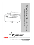
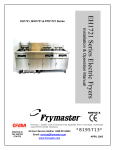
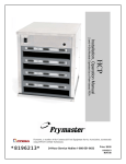
VT SERIES VERTICAL TOASTER
SERVICE MANUAL
This equipment chapter is to be inserted in
the Equipment Manual
MANUFACTURED
EXCLUSIVELY FOR
McDONALD’S®
BY FRYMASTER, L.L.C.
P.O. BOX 51000
SHREVEPORT, LOUISIANA 71135-1000
PHONE 1 (318) 865-1711
1 (800) 24 FRYER
TABLE OF CONTENTS
1.
WARRANTY STATEMENT..............................................................................................................................1
1.1
WARRANTY PROVISIONS – VERTICAL TOASTER............................................................................ 1
1.2
PARTS RETURN.................................................................................................................................... 1
1.3
WARRANTY EXCLUSIONS ................................................................................................................... 1
2.
PARTS ORDERING AND SERVICE INFORMATION .....................................................................................2
3.
VERTICAL TOASTER OPERATIONAL DESCRIPTION ................................................................................3
4.
INSTALLATION/SETUP ..................................................................................................................................3
5.
OPERATION.....................................................................................................................................................3
6.
VIEWING AND ADJUSTING THE SETPOINT ................................................................................................4
7.
ADJUSTING BUN COMPRESSION ................................................................................................................4
8.
CHANGING BELTS .........................................................................................................................................5
9.
OPERATOR TROUBLESHOOTING................................................................................................................6
10. PREVENTIVE MAINTENANCE .......................................................................................................................6
11. SERVICE INFORMATION................................................................................................................................7
11.1 INTRODUCTION .................................................................................................................................... 7
11.2 PARTS LIST ........................................................................................................................................... 8
11.3 SERVICE PROCEDURES.................................................................................................................... 17
11.4 TECHNICIAN TROUBLESHOOTING .................................................................................................. 22
11.5 PROBE RESISTENCE CHART............................................................................................................ 24
11.6 WIRING DIAGRAMS ............................................................................................................................ 25
11.7 SCHEMATIC ........................................................................................................................................ 27
Frymaster L.L.C., 8700 Line Avenue 71106, P.O. Box 51000, Shreveport, Louisiana 71135-1000
TEL 318-865-1711 FAX (Parts) 318-219-7140 (Tech Support) 318-219-7135
Printed in the United States
Service Hotline
1-800-24-FRYER
819-5921 June 2003
FOR YOUR SAFETY:
DO NOT STORE OR USE GASOLINE OR OTHER FLAMMABLE VAPORS AND LIQUIDS IN
THE VICINITY OF THIS OR ANY OTHER APPLIANCE.
DO NOT OPERATE OR SERVICE THE VERTICAL TOASTER WITHOUT FIRST READING
THIS MANUAL
DO NOT OPERATE THE VERTICAL TOASTER UNLESS IT HAS BEEN PROPERLY
INSTALLED AND CHECKED.
DO NOT OPERATE THE VERTICAL TOASTER UNLESS ALL COVERS AND ACCESS
PANELS ARE IN PLACE AND PROPERLY SECURED.
DO NOT ATTEMPT TO REPAIR OR REPLACE ANY COMPONENT OF THE VERTICAL
TOASTER UNLESS ALL POWER TO THE UNIT HAS BEEN DISCONNECTED.
USE CAUTION WHEN SETTING UP, OPERATING, OR CLEANING THE VERTICAL
TOASTER TO AVOID CONTACT WITH HEATED SURFACES.
HAZARD COMMUNICATION STANDARD (HCS) – THE PROCEDURES IN THIS MANUAL
INCLUDE THE USE OF CHEMICAL PRODUCTS. THESE CHEMICAL PRODUCTS WILL
BE PRINTED IN BOLD FACE, FOLLOWED BY THE ABBREVIATION (HCS) IN THE TEXT
PORTION OF THE PROCEDURE. SEE THE HAZARD COMMUNICATION STANDARD
(HCS) MANUAL FOR THE APPROPRIATE MATERIAL SAFETY DATA SHEET(S) (MSDS).
1. WARRANTY STATEMENT
The Frymaster Corporation makes the following limited warranties to the original purchaser only for this
equipment and replacement parts:
1.1 WARRANTY PROVISIONS – VERTICAL TOASTER
A.
The Frymaster Corporation warrants all components against defects in material and workmanship
for a period of 1 year.
B.
All parts, with the exception of belts, are warranted for 1 year after installation date of toaster.
(Belts are consumable items.)
C.
If any parts become defective during the first year after installation date, Frymaster will also pay
straight-time labor costs to replace the part, plus up to 100 miles/160 km of travel (50 miles/80 km
each way).
1.2 PARTS RETURN
All defective in-warranty parts must be returned to a Frymaster Factory Authorized Service Center
within 60 days for credit. After 60 days, no credit will be allowed.
1.3 WARRANTY EXCLUSIONS
This warranty does not cover equipment that has been damaged due to misuse, abuse, alteration, or
accident such as:
• improper or unauthorized repair;
• failure to follow proper installation instructions and/or scheduled maintenance procedures as
prescribed in your MRC cards;
• improper maintenance;
• damage in shipment;
• abnormal use;
• removal, alteration, or obliteration of the rating plate.
This warranty also does not cover:
• transportation or travel over 100 miles/160 km (50 miles/80 km each way), or travel time over
two (2) hours.
• overtime or holiday charges;
• consequential damages (the cost of repairing or replacing other property which is damaged);
loss of time, profits, use or any other incidental damages of any kind.
There are no implied warranties of merchantability or fitness for any particular use or purpose.
For international warranty, the above procedures apply, except that the customer is responsible for
freight and duty charges.
NOTICE
IF, DURING THE WARRANTY PERIOD, THE CUSTOMER USES A PART FOR THIS ENODIS
EQUIPMENT OTHER THAN AN UNMODIFIED NEW OR RECYCLED PART PURCHASED
DIRECTLY FROM FRYMASTER/DEAN, OR ANY OF ITS AUTHORIZED SERVICE CENTERS,
AND/OR THE PART BEING USED IS MODIFIED FROM ITS ORIGINAL CONFIGURATION, THIS
WARRANTY WILL BE VOID. FURTHER, FRYMASTER/DEAN AND ITS AFFILIATES WILL NOT BE
LIABLE FOR ANY CLAIMS, DAMAGES OR EXPENSES INCURRED BY THE CUSTOMER WHICH
ARISE DIRECTLY OR INDIRECTLY, IN WHOLE OR IN PART, DUE TO THE INSTALLATION OF
ANY MODIFIED PART AND/OR PART RECEIVED FROM AN UNAUTHORIZED SERVICE CENTER.
Service Hotline
1-800-24-FRYER
Page 1
2. PARTS ORDERING AND SERVICE INFORMATION
Parts orders may be placed directly with your local Frymaster Factory Authorized Service Center
(FASC)/Distributor. A list of Frymaster FASCs was included with the unit when shipped from the
factory. If you do not have access to this list, contact the Frymaster Service Department at 1-800-24FRYER or 1-318-865-1711.
To speed up your order, the following information is required:
Model Number
Serial Number
Voltage
Part Number
Quantity Needed
Service may be obtained by contacting your local FASC or Distributor. Service information may be
obtained by calling the Frymaster Service Department. The following information will be needed in
order to assist you quickly and efficiently.
Model Number
Serial Number
Nature of Problem
Also include any other information which may be helpful in solving your service problem.
Upper
Compression
Adjustment
Knobs
LED
DISPLAY
REDY
RAISE
SETPOINT
BUTTON
LOWER
SETPOINT
BUTTON
ON/OFF
BUTTON
DISPLAY
TEMPERATURE
BUTTON
Lower
Compression
Adjustment
Knobs
Page 2
Bun Guide for Heel
and Crown Slots
Heated Holding Tray
Service Hotline
1-800-24-FRYER
3. VERTICAL TOASTER OPERATIONAL DESCRIPTION
The Vertical Toaster is designed to produce fresh, uniformly toasted buns on an "as needed” basis.
The countertop-mounted unit consists of a cabinet, a computer, a heating element and a pair of
conveyor assemblies.
When the unit is turned on, an electrical heating element (called a platen) is energized. The platen
heats up to a programmed temperature referred to as the setpoint. At the same time, both conveyor
assemblies are activated. When a bun is placed into one of the slots at the top of the cabinet, the
conveyor belts gently carry it through the unit, with the cut face of the bun passing over the heated
platen. As the bun passes over the platen, it is toasted. At the end of the process, the bun is deposited
onto a heated holding tray that keeps it warm until it is used in a sandwich.
The computer allows the operator to adjust the setpoint to obtain desired toasting characteristics.
Compression adjustment knobs also allow the operator to adjust the compression of heels and crowns
as they pass through the toaster.
4. INSTALLATION/SETUP
Upon arrival, inspect the toaster for concealed damage. Immediately report any damage to the
delivering freight company. Claims must be filed within 15 days after receipt of the unit.
Power Requirements:
ALL ELECTRICALLY OPERATED APPLIANCES MUST BE ELECTRICALLY GROUNDED IN ACCORDANCE WITH LOCAL CODES, OR
IN THE ABSENCE OF LOCAL CODES, WITH THE NATIONAL ELECTRICAL CODE (ANSI/NFPA NO. 70-1990) OR THE
CORRESPONDING NATIONAL CODE OF THE COUNTRY IN WHICH INSTALLED.
THIS APPLIANCE IS EQUIPPED WITH A GROUNDING PLUG FOR YOUR PROTECTION AGAINST SHOCK HAZARD AND MUST BE
PLUGGED INTO A PROPERLY GROUNDED RECEPTACLE. DO NOT CUT OR REMOVE THE GROUNDING PRONG FROM THIS PLUG!
•
•
•
•
Voltage: 208VAC or 240VAC depending on model ordered
Frequency: 60 Hz (non-CE )or 50 Hz (CE and Australian models)
Phase: Single
Service: 20 Amp
Setup:
Setup of the toaster consists of unpacking the unit, placing it on a sturdy table or countertop adjacent to
a properly grounded AC outlet of appropriate voltage, removing the cardboard packing inserts, installing
the bun feeder in the slot on top of the cover, and plugging it in. NOTE: The cover must be closed to
install the bun feeder, and the bun feeder must be removed to open the cover.
The unit is shipped with a programmed setpoint of 550°F (288°C), upper crown compression knob set
to 4, lower crown compression knob set to 5, upper heel compression knob set to D, and lower
compression knob set to E. The operator may change these settings to attain desired toasting.
5. OPERATION
1. Press the ON/OFF
button. The word LOW will appear in the green LED display window. The
unit will take about 10 minutes to reach operating temperature, at which time the display will change
to REDY, indicating the toaster is ready for use.
Service Hotline
1-800-24-FRYER
Page 3
2. Load buns into the appropriate slots (Heel or Crown) one at a time, with the cut faces toward the
rear of the unit. The unit will toast the buns and transfer them to the heated holding tray.
3. Adjust the setpoint and bun compression as necessary to achieve desired toasting.
6. VIEWING AND ADJUSTING THE SETPOINT
To view the platen temperature, press the
button once. The temperature in degrees Fahrenheit will
button twice. The
appear in the green LED display window. To view the current setpoint, press the
setpoint in degrees Fahrenheit will be displayed in the green LED display window. To toggle the
display to Celsius, unplug the unit, then press and hold the
button as the unit is plugged back in.
To change the setpoint:
button). Enter the setpoint programming mode by pressing the
,
1. Turn the unit OFF (press the
,
,
buttons in that order. The current setpoint will appear in the LED display. To increase
the setpoint, press the
button; to decrease it, press the
button.
button once. Press the ON/OFF
button. If
2. When the desired setpoint is displayed, press the
the platen is within 20°F (11°C) of the setpoint, the display will show REDY. Otherwise, the display
will show LOW or HIGH until the platen is within 20°F (11°C) of the setpoint, at which time the
display will change to REDY.
7. ADJUSTING BUN COMPRESSION
1. There are two pairs of compression adjustment knobs (one pair numbered 1-5, the other lettered AE), as shown in the accompanying illustration. Factory settings are circled.
Crown Compression
Adjustment (1-5)
UPPER COMPRESSION LABEL
Heel Compression
Adjustment (A-E)
Crown Compression
Adjustment (1-5)
2. Settings A and 1 cause the greatest bun compression (that is, the thinnest bun after toasting).
Page 4
Service Hotline
1-800-24-FRYER
8. CHANGING BELTS
1. Turn the unit off (press the ON/OFF
button) then unplug it. If the unit has been in operation,
allow it to cool for about 1½ hours. TIP: Change belts in the morning, prior to turning the toaster
on.
2. Remove the bun feeder, and then open the cover.
3. Set the bun compression knobs to positions E and 5.
4. Press down on the top roller and move it to the retracted (down) position. (NOTE: Each side of the
roller must be locked down.)
5. Rotate the tray stabilizer latch upward to unlatch it.
Tray
Stabilizer
Latch
6. Slip the old belt off the rollers and slip the new belt on. When the replacement belt has been
properly positioned between the raised edges of its rollers, rotate the tray stabilizer latch to the
latched position.
7. Press down on the top roller to unlock it and allow it to extend.
8. Close the cover. Return the bun compression knobs to their previous settings.
Service Hotline
1-800-24-FRYER
Page 5
9. OPERATOR TROUBLESHOOTING
PROBLEM
PRO1 in LED display.
PRO2 in LED display.
PROBABLE CAUSES
CORRECTIVE ACTION
A. Indicates failure of main platen probe or A. Call FASC.
associated circuitry.
A. Indicates failure of tray heater probe or
associated circuitry.
A. Cover not properly installed.
Bun conveyors do not start
when ON/OFF button is B. Toaster not plugged in.
pressed. C. Store circuit breaker tripped.
D. Failed cover interlock switch, failed high
limit, failed motor, or failed controller.
A. Call FASC.
A. Make sure cover is correctly positioned so
B.
C.
that the cover interlock switch is
depressed.
Plug toaster in.
Reset circuit breaker.
D. Call FASC.
A. If toasting is too dark, lower the setpoint
and/or compression setting until desired
toasting is achieved.
Toasting is consistently too A. Improper setpoint programmed and/or
dark or too light.
incorrect compression knob setting.
A.
Buns are too thick or too
thin.
Buns are toasting
inconsistently.
A. Compression knobs on an improper
setting for desired compression.
A.
A. Belt slippage.
If toasting is too light, increase setpoint
and/or compression setting until desired
toasting is achieved.
Adjust the compression knobs to achieve
desired compression. Moving them to a
lower setting will increase compression.
Moving them to a higher setting will
decrease compression. Make sure both
pairs of knobs are on the same setting.
Shut down and clean unit, paying
particular attention to grooves in rollers
and condition of belts.
B. Incorrect belt speed, faulty platen heater, B. Call FASC.
or faulty controller.
10. PREVENTIVE MAINTENANCE
A separate set of Maintenance Requirement Cards (MRCs) is furnished with this manual. In addition to the
checks and services contained in the MRCs, Frymaster recommends that this appliance be inspected by a
Frymaster Factory Authorized Service Technician at least annually as follows:
•
Inspect all wiring for signs of chafing, kinking, and/or loose connections.
•
Verify that all mechanical and electronic components are securely mounted (i.e., screws and nuts and bolts are
tight.)
•
Verify that idler roller springs are in serviceable condition (i.e., rollers are held securely in the top of the
J-slots and belts do not slip).
Page 6
Service Hotline
1-800-24-FRYER
11.
SERVICE INFORMATION
11.1 INTRODUCTION
Vertical toasters manufactured for use in the European Union (CE) and those manufactured for use
elsewhere are identical in most respects, but there are some important differences. The paragraphs
that follow summarize the differences and provide a list of the parts that are unique to each model.
The most significant differences are in the electronic components. Units built for the CE and Australian
markets have a 50 Hz motor; all others have a 60 Hz motor. Non-CE and CE/Australian units also use
different transformers, and CE/Australian units have a line filter built into the electrical power supply
system. The line filter and cover are attached to the rear of the cabinet.
Because of the difference in the power cycle frequency (50 Hz vs. 60 Hz), CE and Australian units are
equipped with 10-tooth drive pulleys and a 28-Tooth motor pulley. Standard units have 17-tooth drive
pulleys and an 18-tooth motor pulley. The different pulleys on the CE and Australian units maintain the
correct belt speed even though the RPM of the motor at 50 Hz is slightly slower than that of the motor
at 60 Hz.
The table below identifies the components that are unique to each configuration.
Components Unique to CE andAustralian Units
P/N
807-2191
807-0910
106-0781
807-3472
824-0896
106-2143
810-2300
810-2301
810-2332
Description
Transformer (208-240V/12V)
Transformer Fuse, 250V/3A
Transformer and Bracket Assembly
Line Filter
Line Filter Cover
Tensioner Assembly, Drive Belt
28-Tooth Motor Driven Pulley
10-Tooth Dual Belt Drive Pulley
10-Tooth Toasting Belt Drive Pulley
Components Unique to Non-CE Units
P/N
807-0979
N/A
N/A
N/A
N/A
106-2723
810-2565
810-2566
810-2564
Description
Transformer (208-240V/12V)
Not used.
Not used.
Not used.
Not used.
Tensioner Assembly, Drive Belt
18-Tooth Motor Driven Pulley
17-Tooth Dual Belt Drive Pulley
17-Tooth Toasting Belt Drive Pulley
The illustrations in the parts list that follows also identify the CE/Australian and Non-CE components.
Service Hotline
1-800-24-FRYER
Page 7
11.2 PARTS LIST
16
CABINETRY
17
18
19
20
21
1
27
13
28
14
29
8
11
27
9
16
12
10
23
29
24
7
30
29
6
2
22
26
3
4
30
25
5
Page 8
Service Hotline
1-800-24-FRYER
ITEM
PART #
1
106-2720
2
824-1117
3
816-0573
4
200-4270
5
816-0589
6
823-3988
7
823-2940
8
823-2941
9
210-3434
10
200-2877
11
210-2876
12
810-2331
13
824-0896
14
810-2278
15
106-2158
16
823-3656
17
810-0066
18
810-1683
19
910-9458
20
809-0184
21
809-0107
22
809-0104
23
809-0112
24
809-0247
25
809-0434
26
809-0448
27
826-1330
28
826-1374
29
826-1379
30
826-1389
*
810-1712
* Not illustrated
COMPONENT
Back Cover Assembly
Tray Assembly, Toast
Insulation, Toast Tray
Bottom, Toaster
Seal, Toaster Base
Housing, Component
Bracket, Lower Hinge
Bracket, Upper Hinge
Cover, Air Inlet
Brace, Component Housing
Cover, Component Housing
Knob, Compression Adjustment
Cover, Line Filter (used on CE and Australian units only)
Guide, Bread (Wireform Feeder)
Cover Assembly, Toaster (includes Items 16-21)
Cover (does not include Items 17-21)
Magnet
Handle, Cover
Reinforcement, Cover Side
Washer, #10 Lock
Screw, 8-32 x ⅜-inch Slotted Round Head
Screw, 8-32 x ½-inch Slotted Truss Head
Screw, 8-32 x 1 ¼-inch Slotted Truss Head
Nut, 8-32 Hex
Screw, #10 x ⅜-inch Hex Washer Head
Clip, Tinnerman
Screw, 10-32 x ⅜-inch Slotted Truss Head (Pkg. of 25)
Screw, #10 x ½-inch Hex Head (Pkg. of 25)
Screw, #10 x ½-inch Philips Truss Head (Pkg. of 10)
Screw, ¼-20 x ¾-inch Hex Head (Pkg. of 10)
Clip, Adhesive-backed Wire Routing
Service Hotline
1-800-24-FRYER
Page 9
15
2
11
14
6
13
4
20
23
5
10
7
7
9
1
16
8
17
18
22
5
18
17
24
12
21
19
3
CONVEYOR ASSEMBLY, DUAL BELT
Page 10
Service Hotline
1-800-24-FRYER
ITEM
1
2
3
4
5
6
7
8
9
10
11
12
13
14
15
16
17
18
19
20
21
22
23
24
25
26
PART #
806-9200
806-9318
810-2303
809-0132
826-1374
809-0647
809-0745
810-1672
810-1718
810-1776
810-1802
810-1818
810-2305
816-0389
823-2719
823-3578
823-2722
823-2723
823-2798
823-2838
823-3989
900-8155
910-8254
910-8512
210-4245
210-4246
COMPONENT
Roller Assembly, Dual Belt Idler
Roller Assembly, Dual Belt Drive
Washer, Teflon Crumb
Screw, ¼-20 x ¾-inch Slotted Pan Head
Screw, #10 x ½-inch Hex Head (Pkg. of 25)
E-Ring
Washer, ¼-inch Flat
Spring, Compression Plate
Shaft, Short Dual Belt Roller
Pin, VT Cotter
Bushing, Tray Stabilizer Latch Support
Spring, 3.00-inch Long, 4.6 Lbs./Inch
Bushing
Belt, Dual Conveyor
Plate Assembly, VT Right Pressure
Plate Assembly, VT Left Pressure
Cam Assembly, VT Long
Cam Assembly, VT Short
Cover Assembly, VT Spring
Latch Assembly, VT Tray
Tray Assembly, Dual Belt
Bracket, Guide Rod
Brace, Dual Belt Tray
Bracket, Spring Guide Receiver
Bracket, Left Center Support
Bracket, Right Center Support
Service Hotline
1-800-24-FRYER
Page 11
5
13
27
16
4
17
31
8
15
2
25
28
29
30
10
11
7
19
12
22
18
20
1
3
14
28
6
24
CONVEYOR ASSEMBLY, TOASTING
Page 12
Service Hotline
1-800-24-FRYER
ITEM
PART #
COMPONENT
1
106-2123
Tray with Grommet, VT Platen
2
210-0318
Crumb Shield, Toasting Conveyor
3
806-9195
Roller, VT Toasting Belt Idler
4
806-9196
Platen Assembly, VT
5
810-2017
Roller, VT Toasting Belt Drive
6
810-2103
Washer, Teflon Crumb
7
809-0266
Screw, #10 x ½-inch Philips Truss Head
8
809-0647
E-Ring
9
809-0650
Screw, 10-32 x ⅜-inch Button Socket Head
10
809-0745
Washer, ¼-inch Flat
11
810-1721
Shaft, Long Roller
12
810-1736
Plug, 1.75-inch Stainless Button
13
810-1776
Pin, VT Cotter
14
810-1818
Spring, 3-inches Long, 4.6 Lbs./Inch
15
810-2305
Bushing, Roller
16
816-0379
Belt, Toasting
17
816-0403
Insulation, Platen
18
823-2726
Slide Assembly, Belt Tension
19
910-8246
Guide, Crumb Shield
20
910-8254
Brace, VT Platen Tray
*21*
910-8512
Bracket, Slide Assembly Receiver
22
810-1722
Grommet, .5-inch I.D. x 1.05-inch O.D. (Integral component of Item 1)
23
810-2013
Roller, VT Drive (Integral component of Item 3)
24
810-1810
Bushing, Teflon (Integral component of Item 3)
25
807-3037
Thermostat, High-Limit (Integral component of Item 4)
26
910-8637
Spacer, High-Limit Thermostat (Integral component of Item 4)
27
809-0729
Capscrew, 6-32 x ¼-inch Socket Head (Integral component of Item 4)
28
807-3247
Probe, Heater (Integral component of Item 4)
29
910-8757
Retainer, Heater Probe (Integral component of Item 4)
30
826-1330
Screw, 10-32 x ⅜-inch Slotted Truss Head (Integral component of Item 4)
31
810-1658
Platen, 5000W (Integral component of Item 4)
* Obscured by Item 1. See Item 24 on Page 10 for illustration.
Service Hotline
1-800-24-FRYER
Page 13
9
12
1
13
2
3
8
4
5
6
14
10
11
7
15
16
ELECTRONIC COMPONENTS
Page 14
Service Hotline
1-800-24-FRYER
ITEM
PART #
1
807-3213
2
807-3021
3
826-1562
4
106-0781
*
807-0910
5
807-0979
7
806-9296
8
807-3196
9
807-3064
10
806-9579
11
807-3132
*
816-0573
*
811-0746
12
807-3243
13
807-3198
14
807-3242
15
807-3529
16
807-3850
*Not illustrated.
COMPONENT
Relay, Solid State 5A 3/16 Control Terminals
Relay, 30A 12VDC DPST NO
Relay, Solid State 40A 280V SPST NO
Transformer and Bracket Assembly, CE and Australian
Fuse, 250V 3A (fuse for CE/Australian transformer)
Transformer, 208-240VAC/12VAC, 50/60 Hz, 43VA
Computer Assembly, VT
Heater, 240V 165W Cartridge
Switch, Cover Interlock
Heater Assembly, VT Tray
Probe, VT Tray Heater
Insulation, VT Tray Heater (See Pages 8 and 21 for illustrations.)
Tape, Aluminum (secures probe, tray heater, and insulation to tray)
Cordset, Standard Twist-Lock
Cordset, Hooded Twist-Lock
Cordset, Pin and Sleeve
Cordset, CE VT
Cordset, Australian VT
Service Hotline
1-800-24-FRYER
Page 15
MOTOR, DRIVE TRAIN AND FAN COMPONENTS
See Page 10
8
See Page 12
3
4
7
2
9
1
6
5
ITEM
1
2
3
4
5
PART #
106-3052
106-2841
810-2302
106-2128
826-1368
810-2565
810-2300
6
106-2723
106-2143
7
810-2566
810-2301
8
9
Page 16
810-2564
810-2332
106-2703
COMPONENT
Motor Assembly, 50/60 Hz
200-208V VT Drive
220-250V VT Drive
Drive Belt
Bracket Assembly, VT Idler Pulley
Nut, ¼-20 Serrated Flange (Pkg. of 10)
Pulley, Motor Driven
18-Tooth (Non-CE
28-Tooth (CE and Australian)
Tensioner Assembly, Drive Belt
Non-CE
CE and Australian
Pulley, Dual Belt Drive
17-Tooth (Non-CE)
10-Tooth (CE and Australian)
Pulley, 17-Tooth Toasting Belt Drive
17-Tooth (Non-CE)
10-Tooth (CE and Australian)
Fan Assembly, VT Motor Cooling
Service Hotline
1-800-24-FRYER
11.3 SERVICE PROCEDURES
NOTE: Unless power is necessary for troubleshooting, turn the unit off and unplug it whenever
performing service on this equipment.
Accessing the Electronics
1. Pull the bun compression knobs off their shafts.
2. Remove the screws around the edge of the component housing cover and remove the cover.
Accessing the Drive Motor, Tray Heater, and Auxiliary Transformer
Carefully lay the unit on its back and remove the seven screws that secure the bottom cover in place.
Removing the Conveyor Assemblies
1. Turn off and unplug the unit.
2. Remove the bun feeder then remove the cover by lifting it straight up until it is clear of its hinge
pins.
3. Rotate the bun compression knobs to positions 5 and E.
4. Press down on the top roller(s) of the conveyor assembly to be removed to lock it (them) in the
down position.
5. Rotate the tray stabilizer latch upward, then remove the belt(s). Return the tray stabilizer latch to
the latched position.
6. Pull the bun compression knobs from their shafts.
7. Remove the screws around the edge of the component housing cover and remove the cover.
8. Remove the diagonal brace.
9. Release the tension on the drive belt by pressing down on the belt tensioner arm and remove the
belt from the pulleys.
10. To remove the dual-belt conveyor assembly:
(See illustration on following page.)
a. Loosen the setscrew in the forward-most drive pulley and remove the pulley.
b. Remove the cartridge heater, marking the leads to facilitate reconnection.
c. Remove the four hex-head screws and two flange nuts that secure the conveyor assembly to the
component housing from the inside.
d. Rotate the tray stabilizer latch upward and, while supporting the conveyor assembly, remove the
two hex-head screws securing the top of the conveyor assembly from the outside (conveyor
side) of the component housing and carefully pull the conveyor assembly away from the housing.
e. Reinstall the conveyor assembly by reversing the steps performed, being sure to reattach the
ground wire with the top hex head screw.
Service Hotline
1-800-24-FRYER
Page 17
Step 10d - Remove last two screws
and pull conveyor away from housing.
Step 10c - Remove
these four hex head
screws and two nuts.
Step 10b - Remove
cartridge heater.
Step 10a - Remove drive pulley.
11. To remove the toasting conveyor assembly:
(See illustration on following page.)
a. Detach the platen and probe wiring from the relay, high-limit, and 9-pin connector.
b. Loosen the setscrew in the second drive pulley from the front and remove the pulley.
c. Remove the five flange nuts that secure the idler assembly to the housing and remove the idler
assembly.
d. Remove the two hex head screws shown in Step 11d of the illustration on the following page.
Page 18
Service Hotline
1-800-24-FRYER
e. Rotate the tray stabilizer latch upward and, while supporting the conveyor assembly, remove the
hex-head screw securing the top of the assembly from the outside (conveyor side) of the
component housing and carefully pull the assembly away from the housing.
Step 11e - Remove the last screw and pull
the conveyor away from the housing.
Step 11c - Remove
these five flange nuts
and the idler assembly.
Step 11d - Remove these
two hex head screws.
Step 11b - Remove the drive pulley.
f.
Reinstall the conveyor assembly by reversing the steps performed, being sure to reattach the
two ground wires with the lower of the two hex head screws removed in Step 11d.
Replacing the High-Limit Thermostat or Heater Probe
(See illustration on following page.)
1. Turn off and unplug the unit, and remove toasting conveyor in accordance with the instructions on
Pages 18-19.
2. To replace the high-limit thermostat, remove the platen tray brace to expose the thermostat and
remove the screws securing it in place.
3. To replace the heater probe, remove the plug over the probe to expose the component. Remove
the screw securing the probe retainer and remove the probe.
Service Hotline
1-800-24-FRYER
Page 19
Heater Probe
NOTE: Probe
and high limit
wires must be
routed through
this bushing as
shown by large
arrow.
High Limit
Plug
Platen Tray Brace
4. Replace the failed component, being sure to route the component wires through the bushing as
shown in the illustration above. Reassemble by reversing the steps performed and reconnect the
wiring in accordance with the wiring diagram on the inside of the component housing cover.
Replacing the Drive Motor, Auxiliary Transformer, Tray Heater or Tray Heater Probe
1. Turn off and unplug the unit.
2. Pull the bun compression knobs from their shafts.
3. Remove the screws around the edge of the component housing cover.
4. Disconnect the failed component’s wiring, then carefully lay the unit on its back.
5. Remove the screws that secure the bottom cover in place and remove the cover. NOTE: The two
cap screws that pass through the bottom of the component housing also hold the belt tensioner
assembly in place.
6. To replace the drive motor, remove the screws that secure the diagonal brace to the component
housing. Remove the drive belt. Loosen the setscrew securing the motor pulley to the motor shaft
and remove the pulley. Hold the replacement motor next to the failed motor and transfer the wiring
connections to the replacement. Remove the four screws that secure the motor to the cabinet and
install the replacement.
7. To replace the auxiliary transformer (present only in 200V and 208V units), hold the replacement
next to the failed transformer and, one at a time, disconnect the wires from the failed transformer
and connect them to the replacement. When all wiring has been transferred, remove the screws
Page 20
Service Hotline
1-800-24-FRYER
and nuts that secure the transformer to the back wall of the motor compartment and install the
replacement.
8. To replace the probe, use a sharp knife to cut the aluminum tape that secures the foil-backed
insulation to the bottom of the tray and remove the insulation. Cut the aluminum tape that secures
the heater to the tray and peel back the heater to expose and remove the probe. To replace the
tray heater, peel it completely off.
Use aluminum tape to attach
probe to bottom of tray.
Probe
Tray heater
Foil-backed
insulation
Short screws
Use aluminum tape to attach
tray heater and foil backed
insulation to bottom of tray.
9. Reverse the steps performed to reassemble unit.
Replacing the Dual Belt Conveyor Cartridge Heater
1. Turn off and unplug the unit.
2. Pull the bun compression knobs off their shafts.
3. Remove the screws in the edge of the component housing cover.
4. Disconnect the heater leads. Remove the hex-head screws securing the heater in place and
remove the heater (see illustration on Page 18).
5. Reverse steps 1-4 to reassemble the unit.
Replacing the Transformer or Relays
1. Turn off and unplug the unit.
2. Pull the bun compression knobs from their shafts.
3. Remove the screws in the edge of the component housing cover.
4. Hold the replacement component next to the component to be replaced and, one at a time,
disconnect the wires from the failed component and connect them to the replacement component.
Service Hotline
1-800-24-FRYER
Page 21
5. Remove the screws and/or nuts securing the failed component to the component housing and
install the replacement.
6. Reverse steps 1-3 to reassemble the unit.
11.4 TECHNICIAN TROUBLESHOOTING
PROBLEM
PROBABLE CAUSES
CORRECTIVE ACTION
A. Check for line voltage on the primary
A. Failed transformer.
Display remains blank
when unit turned on.
B.
B. Failed computer.
C. Failed cover interlock switch or failed
C.
high limit.
A. Failed motor.
Computer display is on, but
motor is not running B. Broken/loose wire between computer and
latch relay or failed latch relay.
Motor is running at wrong
speed (i.e. average time for
three individual buns to A. Toaster improperly configured for power
pass through toaster is
supply.
NOT between 15 and 18
seconds).
A. Improper power-supply.
A.
B.
A. Check data plate for voltage rating, and
verify that power supply and toaster
match.
A. Verify that the power supply is 20 amp
B.
B. Failed temperature probe.
Platen heats, but unit does
not reach setpoint.
C.
C. Failed computer.
Page 22
Service Hotline
1-800-24-FRYER
(line) side of transformer and 12VAC on
secondary (load) side of transformer. If
line voltage is present but secondary
voltage is not 12VAC, the transformer has
failed.
Check continuity between right terminal
of secondary (load) side of transformer
and Pin 9 of the 9-pin connector when the
cover interlock switch is closed. If
resistance is zero, replace the computer.
Check continuity between switch
terminals when the switch is closed.
If resistance is infinite, replace switch. If
resistance is zero, replace high limit.
If platen is heating, replace motor.
Check for 12VDC on Pins 6 & 7 of
computer. If present and wiring is intact,
replace latch relay. If not present, replace
computer.
single-phase 200, 208 or 240VAC
(depending upon model).
Use a temperature-measuring device to
determine actual platen temperature. If
measured temperature is within 10 degrees
of the temperature displayed on the
computer and the probe resistance at pins
3 and 5 of the 9-pin connector does not
correspond to the appropriate value in the
probe resistance chart on Pages 24 and 25,
replace the probe.
Use a temperature-measuring device to
determine actual platen temperature. If
measured temperature is within 10 degrees
of the temperature displayed on the
computer and probe resistance at pins 3
and 5 of the 9-pin connector corresponds
to the value in the probe resistance chart
on Pages 24 and 25, replace the computer.
PROBLEM
PROBABLE CAUSES
CORRECTIVE ACTION
A. Check for 12VDC on computer pins 6 &
A. Failed computer.
B. Broken/loose wire between computer and B.
latch relay, or failed latch relay.
C.
Platen does not heat, but
computer display is on. C. Failed main heater probe.
D. Broken/loose wire between computer and
D.
main heater relay, or failed main heater
relay.
E.
E. Failed platen.
A.
A. Failed computer.
B. Broken/loose wire between computer and B.
latch relay, or failed latch relay.
C.
Tray heater does not heat,
but computer display is on.
C. Failed tray heater probe.
D. Broken/loose wire between computer and
D.
tray heater relay, or failed tray heater
relay.
E.
E. Failed tray heater.
Service Hotline
1-800-24-FRYER
7. If NOT present AND motor is running,
replace computer. Check for 5VDC on
terminals 3 & 4 of main heater relay and
pins 1 and 6 of computer. If NOT present
at either point AND motor is running,
replace computer.
Check for 12VDC on computer pins 6 &
7. If present and wiring is intact, replace
latch relay.
Determine temperature of platen then
measure main heater probe resistance at
pins 3 & 5 of 9-pin connector. If the
probe resistance is NOT approximately
equal to the corresponding resistance in
the chart on Pages 24 and 25, replace the
probe.
Check for 5VDC on terminals 3 & 4 of
main heater relay AND on computer pins
1 & 6. If present on pins 1 & 6, but NOT
on terminals 3 & 4, and wiring is intact,
replace the main heater relay.
Check for 5VDC on terminals 3 & 4 of
main heater relay and for line voltage on
terminal 2 of main heater relay and
terminal 4 of latch relay. If expected
voltage is present at all three points,
replace the platen.
Check for 12VDC on computer pins 6 &
7. If NOT present AND motor is running,
replace computer. Check for 5VDC on
terminals 3 & 4 of main heater relay and
pins 2 and 6 of computer. If NOT present
at either point AND motor is running,
replace computer.
Check for 12VDC on computer pins 6 &
7. If present and wiring is intact, replace
latch relay.
Determine temperature of tray heater then
measure tray heater probe resistance at pin
4 of 9-pin connector and ground. If the
probe resistance is NOT approximately
equal to the corresponding resistance in
the chart on Pages 24 and 25, replace the
probe.
Check for 5VDC on terminals 3 & 4 of
tray heater relay AND on computer pins 2
& 6. If present on pins 2 & 6, but NOT on
terminals 3 & 4, and wiring is intact,
replace the tray heater relay.
Check for 5VDC on terminals 3 & 4 of
main heater relay and for line voltage on
terminal 2 of tray heater relay and
terminal 4 of latch relay. If expected
voltage is present at all three points,
replace the tray heater.
Page 23
11.5 PROBE RESISTANCE CHART
Probe Resistance Chart
For use with VT Series toasters manufactured with Minco Thermistor probes only.
F
60
65
70
75
80
85
90
95
100
105
110
115
120
125
130
135
140
145
150
155
OHMS
1059
1070
1080
1091
1101
1112
1122
1133
1143
1154
1164
1174
1185
1195
1204
1216
1226
1237
1247
1258
Page 24
C
16
18
21
24
27
29
32
35
38
41
43
46
49
52
54
57
60
63
66
68
F
160
165
170
175
180
185
190
195
200
205
210
215
220
225
230
235
240
245
250
255
OHMS
1268
1278
1289
1299
1309
1320
1330
1340
1350
1361
1371
1381
1391
1402
1412
1422
1432
1442
1453
1463
C
71
74
77
79
82
85
88
91
93
96
99
102
104
107
110
113
116
118
121
124
F
260
265
270
275
280
285
290
295
300
305
310
315
320
325
330
335
340
345
350
355
OHMS
1473
1483
1493
1503
1514
1524
1534
1544
1554
1564
1574
1584
1594
1604
1614
1624
1634
1644
1654
1664
C
127
129
132
135
138
141
143
146
149
152
154
157
160
163
166
168
171
174
177
179
Service Hotline
1-800-24-FRYER
F
360
365
370
375
380
385
390
395
400
405
410
415
420
425
430
435
440
445
450
455
OHMS
1674
1684
1694
1704
1714
1724
1734
1744
1754
1764
1774
1783
1793
1803
1813
1823
1833
1843
1852
1862
C
182
185
188
191
193
196
199
202
204
207
210
213
216
218
221
224
227
229
232
235
F
460
465
470
475
480
485
490
495
500
505
510
515
520
525
530
535
540
545
550
OHMS
1872
1882
1892
1901
1911
1921
1931
1940
1950
1960
1969
1979
1989
1998
2008
2018
2029
2039
2049
C
238
241
243
246
249
252
254
257
260
263
266
268
271
274
277
279
282
286
288
11.6 WIRING DIAGRAMS
NOTE: These diagrams depict wiring as of the date of manual publication. They may not
reflect design changes made to the equipment after publication. Always refer to the
wiring diagram affixed to the unit when actually troubleshooting or servicing this
equipment.
NON-CE TOASTERS
Service Hotline
1-800-24-FRYER
Page 25
Service Hotline
1-800-24-FRYER
*
*
GRN/YEL
BLK
17C WHT
15C BLK
FILTER
WHT
14C WHT
DRIVE MOTOR
13C BLK
23C BLK
24C WHT
18C BLK
1C BLK
0
4
12
FUSE
24
0
23
0
20
8
8C BLK
3C BLK
20C BLK
FOR 240 VOLT OPERATION
CONNECT TO PROPER
TRANSFORMER TAP.
4C WHT
VS
EC
TR
AN
SF
OR
ME
R
2C
K
BL
2
1
8
6
12C BRN
21C WHT
*
2 3
5 6
4
1
8 9
7
*
TRAY HEATER
TRAY
PROBE
COVER
LOCK OUT
8051358A
MAIN HEATER
CARTRIDGE HEATER
MAIN
HEATER
PROBE
HIGH LIMIT
.250 FEMALE FULL INSULATED TO .250 MALE FULL INSULATED
WHERE INDICATED BY AN *
16C RED
11C WHT
9C ORG
Page 26
5C YEL
POWER IN
CE AND AUSTRALIAN TOASTERS
11.7 SCHEMATIC
LINE VOLTAGE
LINE FILTER (AUSTRALIAN TOASTERS ONLY)
Transformer
COM NO
12Volt
Secondary
Cover
Interlock
8
High
Limit
9
3
COMPUTER
6
Main
Heater
Probe
5
4
1
7
Tray
Heater
Probe
2
Latch 1
Relay
0
6
8
3
4
2
2
4
Tray 3
Heater
Relay
Main
Heater
Relay
4
Main
Heater
1
2
Cartridge
Heater
1
Tray
Heater
Drive Motor
M
Service Hotline
1-800-24-FRYER
Page 27