1
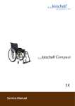
Service Manual
Service Manual
Contents
General ......................................................................................................................... 4
Introduction
4
Spare parts and adaptations
4
Fastening with hexagon socket bolts
4
Torque
5
Checks
5
Identifying and repairing faults
5
Frame ......................................................................................................................... 6
Rear frame
7
Front frame
7
Retaining lever
7
Seat ............................................................................................................................... 8
Seat height front (SHv)
8
Seat height rear (SHh)
9
Seat width (SB)
9
Seat depth (ST)
9
Backrest ...................................................................................................................... 11
Backrest height
11
Adjustable-angle backrest
12
Replacing push handles / push handles and
backrest
14
Footrests..................................................................................................................... 18
One-piece footrest
18
Two-piece footrest
20
Two-piece footrest, adjustable-angle
20
Sideparts .................................................................................................................... 21
Clothes guard/mudguard
21
Siderests
22
Front wheels............................................................................................................... 25
Castor fork
25
Special housing guides
26
Rear wheels ................................................................................................................ 27
Adjusting the seat height rear
27
Tipping stability
27
Wheel camber
28
Adapter plate for drum brake
28
Distance sleeves for rear wheels
28
Brakes ......................................................................................................................... 29
Parking brakes
29
Drum brake
30
Options & accessories ............................................................................................... 31
Antitipper
31
Tipper aid
32
Cane holder
32
Transit wheels
33
3
© Küschall AG, Schweiz | 03/2010
Service Manual
General
Introduction
This Service Manual contains all the technical information necessary for the
inspection, configuration or repair of a Küschall® wheelchair.
To maintain the necessary levels of safety and reliability, every wheelchair
must be thoroughly examined once a year.
Some aspects of the assembly and configuration of the wheelchair require
a high level of expertise. These assembly instructions therefore break the
various tasks down into 3 categories:
Requirement
Symbol
Easy – technical understanding required
z{{
Medium – technical knowledge required
zz{
Difficult – technical knowledge and expertise in assembling wheelchairs required
zzz
The required tools and their sizes are listed before the instructions. The
various torque values with which the nuts are to be tightened are also
specified in the instructions. A torque spanner must be used, in order to
comply with the specified torque values.
Tool
Symbol
Allen key
¥ 3, 4, 5
Torx wrench
Á 10
Phillips head screwdriver
´
Open-end spanner
Socket spanner/Box spanner
8, 9, 10, 18
8, 10, 19, 22
Spare parts and adaptations
All spare parts may be obtained from the Küschall customer service department.
An electronic spare parts catalogue can be found at www.kueschall.
com. Only original spare parts may be used. The written authorisation of
Küschall AG must be obtained before installing additional adaptations on a
Küschall wheelchair.
Fastening with hexagon socket bolts
Hexagon socket bolts are not designed to withstand an excessive application
of force. When tightening or undoing a hexagon socket bolt, force should
be applied to the nut wherever possible to avoid damaging the bolt.
Tightening and undoing
Turn the nut using a socket spanner (only use an open-end spanner if
there is insufficient space), using the Allen key simply to stop the bolt
turning.
Tightening and undoing when no nut is present
If a hexagon socket bolt is screwed directly into a thread, the bolt must be
tightened using the Allen key.
L and not worn.
Ensure that the Allen key is of good quality
4
© Küschall AG, Schweiz | 03/2010
Service Manual
Torque
All bolts must be tightened with the torque specified in the following instructions. If no value
is specified, tighten with 7 Nm.
Checks
Visual check
Check the entire frame for cracks, especially in the vicinity of joints and weld seams (frame,
axle clamp components, back).
Check of the bolts
Check that all bolts have been tightened with the torque specified in the instructions.
M adhesive again. The most important bolts with adhesive are:
Several bolts are secured with adhesive. If these are loosened, they have to be secured with
t
Central bolt on the cross (high-strength adhesive, 3 Nm)
t
Longitudinal stopping bolts on the seat edge (=bolts, which come to rest on either side of the
rear seat locking mechanisms when the seat is unfolded) (low-strength adhesive, 13 Nm)
Identifying and repairing faults
Fault
The wheelchair does not
travel in a straight line
The wheelchair tips too
easily
The brakes are gripping
poorly or asymmetrically
The rolling resistance is very
high
The front wheels wobble
when moving fast
Possible cause
Action
Incorrect tyre pressure on one rear wheel
Correct tyre pressure
One or more spokes broken
Replace broken spoke(s)
Spokes tightened unevenly
Front wheel bearings are dirty or damaged
Support bearings in forks faulty
Tighten loose spokes
Clean or replace the bearings
Replace the support bearings
Steering error or trail angle, left and right, uneven
Adjust steering error or trail angle
Rear wheels are mounted too far forwards
Backrest angle too large
Incorrect tyre pressure in one or both rear tyres
Brake setting incorrect
Mount the rear wheels further back
Reduce backrest angle
Mount the adapter plate lower on the side
profile
Correct tyre pressure
Correct brake setting
Tyre pressure in rear tyres is too low
Correct tyre pressure
Seat angle too large
Rear wheels not parallel
Make rear wheels parallel
Drum brake set too narrow
Bearings are dirty or faulty
Too little tension on the clevis pin housing
Set the drum brake
Replace the bearings
Tighten the nut on the castor fork slightly
Front wheel has worn smooth
Replace front wheel
The front wheel is stiff or
stuck
Bearings are dirty or faulty
Replace the bearings
The wheelchair is very
difficult to unfold
The backrest cover is too tight
Loosen the topmost Velcro band of the backrest
cover a little
Left and right side of the
wheelchair can be moved in
parallel to one another
Longitudinal stopping bolts on the seat edge are loose
Tighten the longitudinal stopping bolts on the
seat edge
5
© Küschall AG, Schweiz | 03/2010
Service Manual
Frame
Frame
8
Rear frame
Retaining lever
Cross
Front frame
7
Upper connecting tube
Lower connecting tube
Seat locking mechanism
Longitudinal stopping bolts
1
2
3
4
8
2
2b
2c
1b
2a
4b
5
1
6
7
2
5
1b
4c
4b
1a
3
4a
1a
6
4
4a
6
© Küschall AG, Schweiz | 03/2010
Service Manual
Frame
Rear frame
Replacing the rear frame
Difficulty: zz{
Tool: ¥ 5
10
Remove backrest.
Loosen and remove bolts 1a and 1b.
Pull out rear frame to the back.
Push the rear frame onto the upper and lower connecting tubes.
Reinsert and tighten bolts 1a and 1b
(torque 1a: 13 Nm, 1b: 7 Nm).
Front frame
Replacing the front frame
Difficulty: zz{
Tool: ¥ 3, 4, 5
10
Disassemble brakes.
Loosen and remove bolts 4a and 4b on both sides. If a flip to back side rest is
fitted, also loosen 4c.
Pull out front frame to the front.
Remove seat locking mechanism with threaded insert from old front
frame and fit it on the new front frame (
Section Seat; Turning the seat
locking mechanism).
Push the front frame onto the upper and lower connecting tube.
Reinsert and tighten bolts 4a, 4b (if required 4c) on both sides (torque 4a:
13 Nm, 4b: 7 Nm, 4c: 7 Nm).
Set the castor fork angle (
Section Front wheels; Castor fork, Setting the
steering error angle).
Retaining lever
Replacing the retaining lever
Difficulty: zz{
Tool: ¥ 3, 4, 5
10
With mudguard or clothes guard, fixed: remove 1a and 4b, with mudguard
or side rest, insertable and siderest, foldable: remove 1a and 1b.
Remove bolt 2a.
Pull the retaining lever from the upper connecting tube .
Remove sleeve 2b.
Push the new retaining lever over the upper connecting tube .
Position sleeve 2b with wide edge in joint 2c.
Secure retaining lever with bolt 2a (4 Nm).
With mudguard or clothes guard, fixed: reinsert and tighten bolts 1a
and 4b, with mudguard or side rest, insertable and side rest, flip to back:
reinsert and tighten bolts 1a and 1b
(torque 1a: 13 Nm, 1b: 7 Nm, 4b: 7 Nm)
7
© Küschall AG, Schweiz | 03/2010
Service Manual
Seat
Seat
Seat height front (SHv)
Options for changing the SHv:
t
Replace front wheel with larger or smaller one or fit it at another position on the castor wheel (
Section Front wheels)
t
Replace castor fork with a larger or a smaller one (
Section Front
wheels)
t
Fit it high/low with the housing guide ‹Hemi› (
Section Front wheels)
Seat height front with respect to fork size, castor fork size and position in the fork
Castor fork [inch]
SHv [cm]
41
3''
42
3''
43/44
4''
3''
45
4''
3''
46
5''
4''
3''
47
5''
4''
3''
48/49
6'' *
5''
4''
3''
50
6'' *
5''
4''
3''
51
7'' *
6'' *
5''
4''
7'' *
6'' *
5''
7'' *
6'' *
52
53/54
(Assumption: Seat depth = 40 cm, seat angle = 5 cm)
fitted high: SHv - 3 cm
fitted low: SHv + 3 cm
* 6’’ and 7’’ front wheels cannot be used on the Ultra-Light dynamic frame (80°), if a 2-part angled footrest is fitted.
8
© Küschall AG, Schweiz | 03/2010
Service Manual
Seat
Seat height rear (SHh)
Options for changing the SHh:
t
Replace rear wheel with a larger or a smaller one
t
Change the position of the adapter plate (
Section Rear wheels)
Seat height rear with respect to the rear wheels and positioning on the frame
SHh [cm]
22’’
Rear wheel size [inch]
24’’
25’’
37
1
38
2
39
3
1
40/41
4
2
26’’
1
2
3
4
5
6
7
8
9
10
11
12
1
42
5
3
2
1
43
6
4
3
2
44
7
5
4
3
45/46
8
6
5
4
47
9
7
6
5
48
10
8
7
6
49
9
8
7
50
10
9
8
Seat width (SB)
SBs range from 28 - 50 cm.
Once the SB is specified, it is very difficult to change it: the cross struts, backrest cover (on standard backs) and, on some configurations, the footrests
must be replaced.
Seat depth (ST)
STs range from 32 - 50 cm.
To reduce the ST, the cross struts must be shortened and a new appropriately sized seat cover fitted. At an ST ≥ 40 cm, the frame can be shortened.
To enlarge the ST, new cross struts, a new appropriately sized seat cover and,
depending on the ST, a new frame must be installed.
9
© Küschall AG, Schweiz | 03/2010
Service Manual
Seat
Replacing the seat cover
Tool: Á 10
Difficulty: zz{
Loosen bolts and remove plug .
Remove seat cover including plastic rods.
Position new seat cover. Adjust seat cover to width SB + 2.5 cm.
Retighten bolts (4 Nm) and plug .
1
2
Turning the seat locking mechanism
If the seat edge can be too easily removed from the seat locking mechanisms, either the front two or all four seat locking mechanisms can be rotated by 180°:
Tool: ¥ 3
Difficulty: z{{
Loosen bolt in seat locking mechanism.
Turn seat locking mechanism by 180°.
Secure bolt with adhesive (low-strength).
Retighten the bolt (4 Nm).
L can be turned as otherwise the threaded insert can move and is then
Screw out the bolt only to the extent that the seat locking mechanism
difficult to re-position.)
1
10
© Küschall AG, Schweiz | 03/2010
Service Manual
Backrest
Backrest
Backrest height
The backrest height can be changed by fitting the telescopic tubes into another position in the backrest tubes. If this setting option is insufficient, the
telescopic tubes can be replaced.
Adjusting the height of standard backrests
Difficulty: z{{
Tool: ¥ 3, 4, 6
8, 10
3
Push the backrest cover upwards and remove the bolt on both
1
sides.
Push the push handles upwards or downwards until you reach the
required height. Replace the bolt and tighten.
L
2
If this setting range is insufficient, use new push handle tubes.
L cover may have to be fitted.
If the backrest height was changed considerably, a new backrest
Adjusting the height of Velcro® adjustable backrests
Difficulty: z{{
Tool: ¥ 3, 4, 6
8, 10
Remove backrest cover and move the Velcro® bands until bolt is
visible.
Remove bolt and move the push handle tube to the required height.
Insert bolt into the appropriate hole and tighten.
4
1
L be replaced. An additional Velcro® band may have to be fitted or one
If the backrest height is changed considerably, the push handles must
may have to be removed.
3
2
11
© Küschall AG, Schweiz | 03/2010
Service Manual
Backrest
Adjustable-angle backrest
In order to make the backrest angle adjustable, an adjustable-angle backrest can be fitted.
Backrest angle
Position
Deviation
from standard
backrests
Angle between
backrest and seat
1
12°
102°
2
8°
98°
3
4°
94°
4
0°
90°
5
-4°
86°
6
-8°
82°
7
-12°
78°
Fitting an adjustable-angle backrest
Difficulty: zz{
Tool: ¥ 3, 4, 5
8, 10
10
Shorter rear frame (variant III) required.
7
Push the lower joint pin into the rear frame and fix it using a bolt.
Secure backrest tube to the upper joint pin using a bolt. Assemble
the upper and lower joint pins and and secure with bolt (13 Nm).
Retighten the bolt (13 Nm).
6
Set the desired backrest angle and secure in the nearest hole using
10
bolt (13 Nm).
Push the single Velcro® band and then the other Velcro® bands 9
and end band over the backrest tube .
Push the push handle into the telescopic tube and fix at the
required height.
Secure end band on the telescopic tube with a bolt.
3
5
4
2
8
1
12
© Küschall AG, Schweiz | 03/2010
Service Manual
Backrest
Setting the backrest angle
Difficulty: zz{
Tool: ¥ 5
10
10
Remove the backrest cushion and push the Velcro® bands upwards, until the backrest joint is invisible.
Remove the bolt .
Set the desired backrest angle, insert the bolts in the nearest hole
and tighten (13 Nm).
Retighten the bolt (13 Nm).
3
Perform the same setting on both sides.
2
1
Visual check
4
5
By looking from the side check that both backrest tubes are level and thus
that the same angle has been set on both sides.
Fitting the joint for a folding backrest
Difficulty: zz{
Tool: ¥ 4, 5
10
Shorter rear frame (variant III) required.
Set the desired backrest angle, insert bolt in the nearest position
(Pos. 1, 2 or 3) and tighten (13 Nm). (With the curved backrest
tubes, other positions can be achieved in addition to the 3 positions
specified.)
1
Fold down upper joint pin with intermediate backrest tube .
Push the joint housing into the rear frame and fit it using a bolt
(13 Nm).
Backrest angle
Position 1 (rear position): 82°, with curved backrest tube 90°
Position 2 (mid position): 86°, with curved backrest tube 94°
Position 3 (front position): 90°, with curved backrest tube 98°
2
3
4
13
© Küschall AG, Schweiz | 03/2010
Service Manual
Backrest
Replacing push handles / push handles and
backrest
If the push handles are replaced with a different type of push handles, e.g.
height-adjustable ones, it can happen that the rear frame must also be replaced.
Changing the backrest height can also mean that the configuration of the
Velcro® bands must be changed.
Fitting standard push handles
Difficulty: zz{
Tool: ´ ¥ 3, 4, 5
8, 10
Secure the telescopic tube to the rear frame at the required height.
4
Push the backrest bands and end band onto the telescopic
tube , end band first.
Secure end band on the telescopic tube with a bolt.
3
2
1
Fitting height adjustable integrated push handles
Difficulty: zz{
Tool: ´ ¥ 3, 4, 5
8, 10
Special rear frame required for RH 30 – 46.5 (variant II)
Push lower telescopic tube and upper telescopic tube into one
3
another and insert bolt.
Secure pre-assembled element (telescopic tubes and ) at the
required height on the rear frame with a bolt (7 Nm).
6
2
7
Push the Velcro® bands and end band onto the telescopic tubes.
Using the clamp bolt secure the height adjustable push handles 5
through the telescopic tube .
Push in push handle completely.
Secure end band on the telescopic tube with a bolt.
14
1
4
© Küschall AG, Schweiz | 03/2010
Service Manual
Backrest
Fitting height adjustable, rear set push handles
Difficulty: zz{
Tool: ´ ¥ 3, 4, 5
8, 10
The Velcro® bands may have to be replaced with narrower ones, as space is
required to secure the holder on the telescopic tube.
Secure the telescopic tube to the rear frame at the required
6
height.
4
Press the cover cap onto the end of the telescopic tube.
Push the Velcro® bands onto the telescopic tube.
Push the holder onto the telescopic tube and fix in place by
2
tightening the clamp bolts (13 Nm).
Fit end band onto the telescopic tube and secure with a bolt.
5
Attach protective cushion.
3
1
Fitting angle-adjustable backrest with height-adjustable push
handles
Difficulty: zz{
Tool: ´ ¥ 3, 4, 5
8, 10
10
7
11
Shorter rear frame (variant III) required.
Push the lower joint pin into the rear frame and fix it using the
bolts.
Fit backrest tube onto the upper joint pin using bolts. Assemble
the upper and lower joint pins and and secure with a bolt (13
Nm).
10
3
Set the desired backrest angle and secure in the nearest hole using a
5
4
Retighten the bolt (13 Nm).
2
nut and bolt (13 Nm).
6
9
Push the single Velcro® band and then the other Velcro® bands and end band over the backrest tube .
1
Push in push handle completely.
Using the clamp bolt D fit the height-adjustable push handles 8
through the telescopic tube .
Fit end band onto the telescopic tube with a bolt.
15
© Küschall AG, Schweiz | 03/2010
Service Manual
Backrest
Backrest with adjustable backs with respect to push handles
Backrest
height
(RH)
Standard
push
handles
Folding
push
handles
Height-adjustable
integrated push
handles
Velcro
bands
30
S
S
S
XXS
S
XXS
S
4B
S
31.5
S
S
S
XS
S
XS
S
4B
S
33
S
S
S
S
S
S
S
4B
S
34.5
S
S
L
M
S
M
L
4B
S
36
S
S
L
M
S
M
L
4B
S
37.5
S
S
L
M
S
M
L
4B
S
39
S/M
S/M
L
M
S
M
L
4B
M
40.5
S/M
S/M
L
M
S
M
L
4B
M
42
S/M
S/M
L
M
S
M
S
6B
M
43.5
M
M
L
L
L
L
S
6B
M
45
M
M
L
L
L
L
S
6B
M
46.5
M
M
L
L
L
L
L
6B
M
48
M
M
L
L
L
L
L
6B
L
49.5
M
M
L
L
L
L
L
6B
L
51
M
M
L
L
L
L
L
6B
L
2B
4B
Assumption: No stabilising bar fitted
Angle-adjustable backrest with adjustable backs with respect to push handles
Folding
push
handles
Height-adjustable
integrated push
handles
Velcro bands
L
1B+2B
S
S
L
1B+2B
S
S
S
1B+4B
S
S
L
S
1B+4B
S
S
L
S
1B+4B
S
S
S
L
L
1B+4B
S
L
1B+4B
M
L
1B+4B
M
30
S
S
S
31.5
S
S
33
S
S
34.5
S
36
S
37.5
39
S/M
S/M
L
40.5
S/M
S/M
L
different for every backrest height
Backrest
height
(RH)
Standard
push
handles
42
S/M
S/M
L
43.5
M
M
L
L
1B+4B
M
S
1B+6B
M
45
M
M
L
S
1B+6B
M
46.5
M
M
L
48
M
M
L
S
1B+6B
M
S
1B+6B
L
49.5
M
M
L
L
1B+6B
L
51
M
M
L
L*
1B+6B*
L
2B
4B
Assumption: No stabilising bar fitted
* For RH51 with height-adjustable integrated push handles: =S, =2x4B
16
© Küschall AG, Schweiz | 03/2010
Service Manual
Backrest
Foldable angle-adjustable backrest with respect to push handles
Backrest
height
(RH)
Standard
push
handles
Folding
push
handles
Height-adjustable
integrated push
handles
Velcro
bands
30
S
S
S
31.5
S
S
S
S
S
33
S
S
S
S
S
34.5
S
S
S
36
S
S
S
37.5
S
S
S
39
S
S
L
40.5
S
S
L
S
S
S
S
S
S
S
different for every backrest height
different for every backrest height
S
L
2B
S
L
2B
S
L*
2B
S
L
2B
M
S
4B
M
S
4B
M
S
4B
M
S
4B
M
42
S
S
L
43.5
M
M
L
45
M
M
L
46.5
M
M
L
L
4B
M
48
M
M
L
L
L
4B
L
S
L
L
49.5
M
M
L
L
L
4B
L
51
M
M
L
L
L
4B
L
2B
4B
Assumption: No stabilising bar fitted
* For RH37.5 with height-adjustable integrated push handles: =S und =2B+4B
Additionally a band is fixed close to the backrest joint. The band is of different length according to the seat
width (SB).
There are 3 lengths: SB 28-36 short, SB 38-44 medium, SB 46-50 long
17
© Küschall AG, Schweiz | 03/2010
Service Manual
Footrests
Footrests
One-piece and two-piece footrests are available.
One-piece footrest
Replacing the footplate
Difficulty: z{{
Tool: ¥ 4
10
Loosen bolts on both sides.
1
Remove footplate and replace with a new one.
Re-insert bolts and tighten (3 Nm).
2
Disassembling/fitting the footrest
Difficulty: z{{
Tool: ¥ 4
8
Remove bolts on both sides.
Pull out the footrest.
1
Insert new footrest.
Tighten bolts on both sides at the same height and in the required
position (4 Nm).
Adjusting the height of the footrest
Difficulty: z{{
Tool: ¥ 4
8
Remove bolts on both sides.
Hold the telescopic tubes with both hands and push the footrest into
the required position.
1
Insert bolts into the nearest hole on both sides and at the same
height and tighten securely (4 Nm).
18
© Küschall AG, Schweiz | 03/2010
Service Manual
Footrests
Centring and adjusting the angle
Difficulty: z{{
Tool: ¥ 4
10
1
Loosen bolts and slightly.
2
Set the same distance from the side tube to the footplate on both sides.
Set the required footplate incline.
Re-tighten bolts (fixed side of the footplate) (13 Nm).
Turn the little tube on the moving side of the footplate such that it
engages properly.
3
Tighten bolts (13 Nm).
Changing the position of the footrest (set to rear – set to front)
Difficulty: z{{
Tool: ¥ 4
10
Loosen bolts on both sides and remove.
1
Turn the footplate with the clamp component.
Re-insert bolts and tighten (13 Nm).
19
© Küschall AG, Schweiz | 03/2010
Service Manual
Footrests
Two-piece footrest
Difficulty: z{{
Tool: ¥ 4
8
Disassembling/fitting footrests
Remove bolts on both sides.
Pull out footrests.
1
Push the new footplates into the frame and at the required height.
Insert bolts into the nearest hole on both sides and at the required
height and tighten (4 Nm).
Adjusting the height of the footrests
Difficulty: z{{
Tool: ¥ 4,
8
Remove bolts .
1
Push the footplates into the required position.
Insert bolts into the nearest hole on both sides and at the required
height and tighten (4 Nm).
Changing the position of the footrests (set to rear –
set to front)
Difficulty: z{{
Tool: ¥ 5
Remove bolts .
Pull the footrests away downwards and replace.
Re-insert bolts and tighten (7 Nm).
1
Two-piece footrest, adjustable-angle
Adjusting the angle
Difficulty: z{{
Tool: ¥ 5
Loosen bolt .
Change the angle of the footrest until it reaches the required position.
Retighten bolt (13 Nm).
1
20
© Küschall AG, Schweiz | 03/2010
Service Manual
Sideparts
Sideparts
Clothes guard/mudguard
1
Fitting the clothes guard/mudguard
Difficulty: zz{
Tool: ¥ 3
8
Fit side fastenings onto the frame.
Fit clothes guard/mudguard with bolts and nuts onto the side
fastenings (4 Nm).
M Fit the mudguard such that it is positioned either < 8 mm or > 25 mm
CAUTION!
2
above the tyres, to avoid the risk of trapping one’s fingers.
Adjusting the clothes guard/mudguard
Difficulty: zz{
Tool: ¥ 3
1
8
Loosen bolts . Move the clothes guard/mudguard .
Retighten bolts (4 Nm).
or
1
Loosen and remove bolts .
2
Re-fit clothes guard/mudguard in another position (4 Nm).
Fitting and adjusting the removable mudguard
Difficulty: zz{
Tool: ¥ 3, 4, 5
1
10
Fit side fastening element with bolts 2a (4 Nm) and 2b (7 Nm).
6
5
Insert mudguard in the side fastening element . Adjust the height
3
by loosening the three bolts on the end stop .
If the edge of the mudguard does not run evenly over the tyre, loosen
4
bolts / and push the mudguard into the required position.
Retighten bolts / (7 Nm).
M Fit the mudguard such that it is positioned either < 8 mm or > 25 mm
CAUTION!
above the tyres, to avoid the risk of trapping one’s fingers.
2a
1
2b
21
© Küschall AG, Schweiz | 03/2010
Service Manual
Sideparts
Siderests
In general a torque of 7 Nm is used to fit the side rests.
Fitting a flip to back side rest in the frame colour
Difficulty: zz{
Tool: ¥ 3, 4, 5
8
10
4
Fit the side fastening element with bolt 1a .
5
6
For bolt 1b, bore a hole with a diameter of 6 mm through the front
3
frame (hole already made in the connecting tube) and fit bolt 1b.
9
Screw the sleeve and bolt onto the rear fastening element .
7
8
2
Fit rear fastening element and clip loosely with bolts and
sleeves (normal rear frame: 1.7 cm beneath the upper edge of the
frame reinforcement, on a shortened rear frame, directly flush with the
upper edge of the frame reinforcement).
1a
1b
Mount the side rest , position rear fastening element precisely.
Attach the wedge and headless bolt .
L and flip to back side rest with engagement mechanism.
To enlarge the distance between the wheels additionally, a different
L adapter sleeve, which is mounted from the inside, has to be applied.
The sleeves are different for flip to back side rest in frame colour
Fitting flip to back side rest with locking mechanism
Difficulty: zz{
Tool: ¥ 3, 4, 5
8
4
10
Fit the side fastening element with bolt 1a .
For bolt 1b, bore a hole with a diameter of 6 mm through the front
frame (hole already made in the connecting tube) and fit bolt 1b.
Screw the sleeve and bolt onto the rear fastening element .
Fit rear fastening element and clip loosely with bolts and
sleeves (normal rear frame: 1.7 cm beneath the upper edge of the
frame reinforcement, on a shortened rear frame, directly flush with the
upper edge of the frame reinforcement).
Mount side rest , position rear fastening element precisely.
5
6
3
9
7
8
2
1a
1b
Attach the wedge and headless bolt .
L and flip to back side rest with engagement mechanism.
To enlarge the distance between the wheels additionally, a different
L adapter sleeve, which is mounted from the inside, has to be applied.
The sleeves are different for flip to back side rest in frame colour
22
© Küschall AG, Schweiz | 03/2010
Service Manual
Sideparts
Fitting side rest insertable, continuously height-adjustable
Difficulty: zz{
Tool ¥ 4, 5
10
Fit the side fastening element with bolts (4 Nm) and (7 Nm).
Insert side rest into the fastening element.
Adjust height by adjusting the clamp component.
1
2
Fitting a simple swivelling armrest
Difficulty: zz{
Tool ¥ 4, 5
Fit the rear fastening element.
Insert the armrest.
Adjust height by adjusting the bolt in the tube of the armrest.
23
© Küschall AG, Schweiz | 03/2010
Service Manual
Sideparts
Size of the clothes guard/mudguard
The clothes guard and mudguard can be adjusted to suit the height of the
rear wheel exactly. Two sizes of each are available:
Clothes guard/mudguard with respect to the position of the rear wheels with standard
adapter plate
Rear wheel 22’’
Rear wheel 24’’
Rear wheel 25’’
Rear wheel 26’’
1
2
3
4
1
2
3
4
1
2
3
4
1
2
3
4
37
L
L
L
L
L
L
L
L
L
L
L
L
L
L
L
L
38
L
L
L
S
L
L
L
L
L
L
L
L
L
L
L
L
39
L
L
L
S
L
L
L
L
L
L
L
L
L
L
L
L
40
L
L
L
S
L
L
L
L
L
L
L
L
L
L
L
L
41
L
L
S
S
L
L
L
S
L
L
L
L
L
L
L
L
42
L
L
S
S
L
L
L
S
L
L
L
L
L
L
L
L
43
L
S
S
S
L
L
L
S
L
L
L
S
L
L
L
L
44
L
S
S
S
L
L
L
S
L
L
L
S
L
L
L
L
45
S
S
S
S
L
L
S
S
L
L
L
S
L
L
L
S
46
S
S
S
S
L
L
S
S
L
L
L
S
L
L
L
S
47
S
S
S
S
L
S
S
S
L
L
S
S
L
L
L
S
48
S
S
S
S
L
S
S
S
L
L
S
S
L
L
L
S
49
S
S
S
S
S
S
S
S
L
S
S
S
L
L
S
S
50
S
S
S
S
S
S
S
S
L
S
S
S
L
L
S
S
SHh
S
S
L
L
Clothes guard/mudguard with respect to the position of the rear wheels with rear wheel
extension
SHh
S
L
S
L
Rear wheel 22’’
Rear wheel 24’’
Rear wheel 25’’
Rear wheel 26’’
5
6
5
6
5
6
5
6
37
L
L
L
L
L
L
L
L
38
S
S
L
L
L
L
L
L
39
S
S
L
L
L
L
L
L
40
S
S
L
L
L
L
L
L
41
S
S
L
L
L
L
L
L
42
S
S
L
L
L
L
L
L
43
S
S
L
L
S
S
S
S
44
S
S
S
S
S
S
S
S
45
S
S
S
S
S
S
S
S
46
S
S
S
S
S
S
S
S
47
S
S
S
S
S
S
S
S
48
S
S
S
S
S
S
S
S
49
S
S
S
S
S
S
S
S
50
S
S
S
S
S
S
S
S
24
© Küschall AG, Schweiz | 03/2010
Service Manual
Front wheels
Front wheels
Replacing the front wheel
Difficulty: z{{
Tool: ¥ 3
Remove bolts , pull out wheel axle .
Remove front wheel and replace with a new one or move to a new
1
position.
(In the case of the Starec wheel, skater wheel, 3’’ sports wheel and the 5’’
soft roll wheel, 2 sleeves must be pushed onto the axle. These sleeves
are already in place on the low-resistance wheel, the sports wheels and
the pneumatic wheels.)
3
1
2
Re-insert axle and tighten bolt (4 Nm).
4
4
Function check
There must be no play in the wheel but it must turn easily.
Castor fork
Replacing the castor fork
Difficulty: zz{
Tool: ¥ 3
19
Remove bolts , wheel axle and front wheel .
Remove nuts and pull the castor fork from the clevis pin.
Replace castor fork and secure with nut such that the fork has no
play.
1
Re-insert the front wheel.
5
2
M Do not overtighten nut , as this can damage the fork bearing.
CAUTION!
4
3
Function check
Tip the wheelchair backwards 90° so that it is lying on the backrest and rear
wheels.
A
Turn the fork up (A) and allow it to swivel down.
The fork is adjusted correctly if it just passes the lowest point and stops there
(B).
B
If the fork moves back when in its lowest position (C), it has not been tightened enough. There is a risk that the front wheels will start to wobble when
travelling at high speeds.
C
25
© Küschall AG, Schweiz | 03/2010
Service Manual
Front wheels
Setting the steering error angle
Difficulty: zz{
Tool: ¥5
10
Loosen bolts and nuts .
1
1
Hold spirit level against the clevis pin housing .
Turn the bolt until the clevis pin housing is vertical.
2
Retighten bolts and nuts (13 Nm).
3
90˚
M It is important that the settings on the left and right are precisely the
4
CAUTION!
same.
Correcting the trail angle
Difficulty: zz{
Tool: ¥5
10
1
Loosen bolts and nuts .
1
Remove clevis pin housing .
Attach adjustment template / (for toe-out: insert template at the
bottom , for toe-in: insert template at the top ).
5
Fit clevis pin housing .
5
Set the angle Manual Castor fork, Adjusting the angle).
2
3
2
4
Special housing guides
Fitting special housing guide for smaller SHv (housing guide,
fitted high)
Difficulty: zz{
Tool: ¥5
10
Remove clevis pin housing .
3
Remove standard housing guide.
Attach bolt .
1
2
Fit special housing guide ‹high› (13 Nm).
Fit clevis pin housing (13 Nm).
Set the angle Manual Castor fork, Adjusting the angle).
Fitting special housing guide for larger SHv
(housing guide, fitted low)
Difficulty: zz{
Tool: ¥5
10
Remove clevis pin housing .
Remove standard housing guide.
Fit special housing guide ‹low› (13 Nm).
1
Fit clevis pin housing (13 Nm).
2
Set the angle Manual Castor fork, Adjusting the angle).
26
© Küschall AG, Schweiz | 03/2010
Rear wheels
Rear wheels
Adjusting the seat height rear
Difficulty: z{{
Tool: ¥ 5
10, 19, 22
Loosen the bolt of the adapter sleeve and bolts .
Remove bolts and move the adapter plate into the required
position.
4
Insert bolts at the appropriate height.
Insert the bolt of the adapter sleeve .
Tighten bolts and (13 Nm).
1
Tighten the bolt of the adapter sleeve (33 Nm).
Perform the same setting on both sides.
2
L (
Manual ‹Castor fork, Adjusting the angle›, Section ‹Front wheels›)
After the SHh is changed, the steering error angle must be checked
3
and with a wheel camber of 3° the angle of the rear wheels must also
be checked (
Manual ‹Changing the wheel camber›, Section ‹Rear
wheels›).
L in order to increase the distance to the rear wheels.
After the SHh is changed, distance sleeves may also have to be fitted
Tipping stability
The tipping stability is influenced by the rear wheel being fitted further forward or further backward on the adapter plate. The further back the adapter
sleeve is fitted, the greater the tipping stability of the wheelchair.
If the rear wheel is to be fitted even further back, a rear wheel extension can
be fitted to increase the tipping stability even more.
1
Adjusting the position of the rear wheel on the adapter plate
Difficulty: z{{
Tool: 19, 22
1
Remove the adapter sleeve .
2
2
Set the adapter sleeve at the required position in the
adapter plate and tighten the nut securely (33 Nm).
Perform the same setting on both sides.
L wheel is changed.
Brakes and mudguard must be repositioned if the position of the rear
Fitting the rear wheel extension
Difficulty: z{{
Tool: ¥ 5
10, 19, 22
Remove the adapter sleeve and adapter plate .
Position the adapter plate for the rear wheel extension at the
required height and tighten securely on the counterpiece using
bolts and (13 Nm). Set the adapter sleeve at the required
position in the adapter plate and tighten the nut securely (33 Nm).
1
4
3
1
2
5
6
Rear wheels
Wheel camber
A wheel camber of either 0° or 3° is possible.
Changing the wheel camber
Difficulty: zzz
0˚
Tool:
18
19, 22
The wheel camber is changed by replacing the adapter sleeve:
Remove adapter sleeve .
Insert new adapter sleeve at the required position on the adapter
3˚
plate and tighten securely (33 Nm).
L using a spirit level to ensure that the rear wheels are parallel to one
To fit a 3° sleeve, the side of the sleeve must be aligned vertically
1
another.
2
3
Visual check
The gap between the wheel and the frame at the front must be the same on
both sides.
The gap between the wheels at the front and rear at axle level must be the
same.
Adapter plate for drum brake
Fitting the adapter plate for the drum brake
Difficulty: z{{
Tool: ¥ 5
4
10
Remove the adapter sleeve and adapter plate .
Position the adapter plate for the drum brake at the required height
1
3
2
and tighten it securely on the counterpiece using bolts and (13
Nm). (
Manual ‹Fitting the drum brake›, Section ‹Brakes›)
5
Distance sleeves for rear wheels
If new side parts are fitted on a wheelchair (side rests, arm rests, clothes
guard or mudguard), the gap between the rear wheels must be increased
by attaching additional distance sleeves. Likewise, distance sleeves may also
have to be fitted if other rear wheels are fitted or if the seat height rear is
altered.
6
Service Manual
Brakes
Brakes
Parking brakes
Fitting/adjusting the parking brake
Difficulty: z{{
Tool: ¥ 5
10
M The parking brakes must be adjusted whenever the rear wheels are
CAUTION!
replaced.
1
Check the air pressure in the rear wheels.
Secure the brake holder loosely to the frame using bolt .
Push the brakes into the brake holder and position, then tighten the
bolt (13 Nm).
L
1
The brake is set correctly if the brake rod presses into the tyre by no
more than 4 mm when the brake is applied and the tyres are properly
pumped.
2
Visual check
Check that the parking brakes are positioned correctly. The brake is set correctly if the brake shoe depresses the tyre by no more than 4 mm when the
brake is applied. (In the case of active brakes and standard brakes this will be
the case when the brake shoe is approx. 25 mm away from the tyre when
released.)
Function check
Place a weighted wheelchair with parking brake engaged facing uphill and
then facing downhill on a ramp with an incline of 7°. The wheelchair should
not move.
29
© Küschall AG, Schweiz | 03/2010
Service Manual
Brakes
Drum brake
2
Fitting the drum brake
Difficulty: zzz
Tool: ¥ 4, ´
9
3
10, 22
Remove standard adapter plate and replace with adapter plate for drum
4
brake (
Manual ‹Fitting adapter plate for drum brake›, Section ‹Rear
wheels›).
Fit the drum brake plate and rotary fixing to adapter plate .
1
Connect the drum brake plate and rotary fixing with bolt (7 Nm).
Fit brake lever on the push handle and secure Bowden cable with
fixing set.
Setting the drum brake
Difficulty: zz{
Tool: 5
Tighten or loosen the brake by turning the setting sleeve .
If the setting sleeve cannot be turned any further, demount brake
cable , loosen clamp bolt using the screwdriver and retighten
the cable.
7
6
30
8
© Küschall AG, Schweiz | 03/2010
Service Manual
Options & accessories
Options & accessories
Antitipper
Fitting an antitipper
Difficulty: z{{
1
Tool: ¥ 5
10
Secure adaptation support with bolt onto the adapter plate (13 Nm).
3
2
Height adjustment
Difficulty: z{{
1
Tool: ¥4
8
3
Loosen bolt and remove the upper end of the antitipper and the
2
holder. Remove the sealing cap (e.g. push it out through the tube
using the screwdriver).
4
Loosen bolt of the antitipper tube and push sleeve into the
correct position.
5
Screw bolt in half way, position spring in sleeve and screw bolt
completely into the tube (7 Nm).
Put all the parts of the antitipper back together; in doing so pull
spring apart, e.g. using a wire hook, and secure it with the top bolt (4 Nm).
Set the antitipper parallel to the wheel chair and tighten the bolts.
1
2
8
7
6
3
7
6
5
Function check
The antitipper should be able to swing underneath the wheelchair without
any difficulty and the distance to the ground must be 4-6 cm.
Tip the wheelchair backwards over the antitipper until the rear wheel axis
is vertically above the support point of the antitipper on the ground. In this
position the distance between the wheel and the ground must be > 3 cm.
31
© Küschall AG, Schweiz | 03/2010
Service Manual
Options & accessories
Tipper aid
Fitting the tipper aid
Difficulty: z{{
1
Tool: ¥ 5
10
Secure adaptation support with bolt onto adapter plate (13 Nm). Push in spring clip and push the tipper aid into the
adaptation support.
4
Make sure that the spring clip is correctly engaged in the adaptation
3
2
support.
Height adjustment
Difficulty: z{{
5
To adjust the height, remove cap and, e.g. using a screwdriver,
4
4
compress the spring inside the tube and push into the required
position..
Cane holder
Fitting a cane holder
Difficulty: z{{
1
Tool: ¥ 5
10
Secure adaptation support with bolt onto adapter plate (13 Nm). Push in spring clip and push the cane holder into the
adaptation support.
4
3
2
Make sure that the spring clip is correctly engaged in the adaptation
support.
Height adjustment
Difficulty: z{{
5
To adjust the height, remove cap and, e.g. using a screwdriver,
4
compress spring inside the tube and push into the required position.
32
4
© Küschall AG, Schweiz | 03/2010
Service Manual
Options & accessories
Transit wheels
Fitting transit wheels
Difficulty: z{{
Tool: ¥ 5,
10 1
Secure adaptation support with bolts onto adapter plate (13 Nm). Push in spring clip and push the transit wheel into the
adaptation support.
4
3
2
Make sure that the spring clip is correctly engaged in the adaptation
support.
4
Height adjustment
Difficulty: z{{
5
To adjust the height, remove cap and, e.g. using a screwdriver,
4
4
compress spring inside the tube and push into the required position..
L spring clip must be pressed in.
To bring the transit wheels into the upper or lower position, the
33
© Küschall AG, Schweiz | 03/2010
Küschall AG
Benkenstrasse 260
CH-4108 Witterswil
[email protected]
www.kueschall.com
Service Manual Ultra Light
ENGLISH | 2010-03
küschall® distributors
Belgium & Luxembourg:*OWBDBSFOWt"VUPCBBOt#-PQQFN
5FM
t'BY
tCFMHJVN!JOWBDBSFDPN
Denmark:*OWBDBSF"4t4ES3JOHWFKt%,#SOECZ
5FM
t'BY
tEFONBSL!JOWBDBSFDPN
Germany:*OWBDBSF"RVBUFD(NC)t"MFNBOOFOTUSBFt%*TOZ
5FM
t'BY
tJOGP!JOWBDBSFBRVBUFDDPN
European Distributor Organisation:*OWBDBSFt,MFJTUTUSBFt%1PSUB8FTUGBMJDB
5FM
t'BY
tFEP!JOWBDBSFDPN
Spain:*OWBDBSF4"tD"SFOZTOt1PMÓHPO*OEVTUSJBMEF$FMSËt&$FMSË(JSPOB
5FM
t'BY
tDPOUBDUTQ!JOWBDBSFDPN
France:*OWBDBSF1PJSJFS4"4t3PVUFEF4U3PDIt''POEFUUFT
5FM
t'BY
tDPOUBDUGS!JOWBDBSFDPN
Ireland:*OWBDBSF*SFMBOE-UEt6OJU4FBUPXO#VTJOFTT$BNQVTt4FBUPXO3PBEt4XPSETt$PVOUZ%VCMJOo*SFMBOE
5FM
tGBY
tJSFMBOE!JOWBDBSFDPN
Italy:*OWBDBSF.FDD4BOTSMt7JBEFJ1JOJt*5IJFOF7*
5FM
t'BY
tJUBMJB!JOWBDBSFDPN
Netherlands:*OWBDBSF#7t$FMTJVTTUSBBUt/-#;&EF
5FM
t'BY
tOFEFSMBOE!JOWBDBSFDPN
Norway:*OWBDBSF"4t(SFOTFTWJOHFOt1PTUCPLTt&UUFSTUBEt/0TMP
5FM
t'BY
tOPSXBZ!JOWBDBSFDPNtJTMBOE!JOWBDBSFDPN
Austria:.PCJUFD.PCJMJUÊUTIJMGFO(NC)t)FS[PH0EJMPTUSBTTFt".POETFF
5FM
t'BY
tPóDF!NPCJUFDBVTUSJBDPNtBVTUSJB!JOWBDBSFDPN
Portugal:*OWBDBSF-EBt3VB&TUSBEB7FMIBtt1-FÎBEP#BMJP
5FM
t'BY
tQPSUVHBM!JOWBDBSFDPN
Sweden & Finland:*OWBDBSF"#t'BHFSTUBHBUBOt44QÌOHB
5FM
t'BY
tTXFEFO!JOWBDBSFDPNtöOMBOE!JOWBDBSFDPN
Switzerland:.PCJUFD3FIBC"(t#FOLFOTUSBTTFt$)8JUUFSTXJM
5FM
t'BY
tTXJU[FSMBOE!JOWBDBSFDPN
United Kingdom:*OWBDBSF6,0QFSBUJPOT-JNJUFEt1FODPFE5FDIOPMPHZ1BSL
1FODPFE#SJEHFOE$');t5FM
'BY
© Küschall AG, Schweiz | 03/2010