1
Service manual
Service manual
Table of contents
General ......................................................................................................................... 4
Introduction
4
Spare parts and adaptations
4
Tightening Allen screws
4
Torque
5
Checks
5
Identifying and alleviating malfunctions
5
Frame ............................................................................................................................ 6
Seat ............................................................................................................................... 7
Seat width (SB)
7
Seat depth (ST)
7
Front seat height (SHv)
7
Rear seat height (SHh)
9
Seat angle (SW)
9
Tipping point adjustment
10
Suspension
10
Backrest ...................................................................................................................... 11
Backrest height (RH)
12
Adjusting the backrest height
12
Replacing the backrest tube
13
Replacing the handle
14
Replacing foldable push handles
14
Backrest angle (RW)
15
Footrests .................................................................................................................... 16
Lower leg length (UL)
16
Replacing footrests
16
Adjusting the footrest height
16
Fitting and adjusting high-mounted footrest
17
Angle-adjustable footplate, adjusting the angle
17
Fit fold-up footrest
17
Side parts ................................................................................................................... 18
Armrest
18
Clothes-guard/mudguard
19
Front wheels............................................................................................................... 21
Replacing a front wheel
21
Replacing a front wheel fork
21
Rear wheels ................................................................................................................ 22
Ensuring the rear wheels are parallel
22
Adjusting the removable axle
22
Fitting and adjusting a rear wheel extension
22
Changing the wheel chamber / Fitting and
adjusting an axle
23
Brakes ......................................................................................................................... 24
Fitting / adjusting the parking brake
24
Options & accessories ............................................................................................... 25
Antitipper
25
Active antitipper
26
Transit wheels
26
3
© Küschall AG, Schweiz | 2010-11
Service manual
General
Introduction
This service manual is part of the instructions and contains the technical
information for servicing, configuring and repairing a Küschall® wheelchair.
In part, assembly and adjustment require extensive experience. For this reason, the following assembly instructions have been split into 3 categories:
Requirement
Symbol
Easy – technical understanding required
z{{
Intermediate – specialist knowledge required
zz{
Difficult – specialist wheelchair assembly knowledgeand
experience required
zzz
GL
SB
The required tools and their respective sizes are listed above each instruction. The instructions include information on the torques with which the
respective screw connections must be tightened. Adhering to the given
torques requires the use of a torque spanner.
Tools
Symbol
Allen key
¥ 3, 4, 5
Phillips screwdriver
´2
Straddle spanner
Socket spanner/ring spanner
10, 11, 19
GB
8, 10
Spare parts and adaptations
All spare parts can be purchased from Küschall's Customer Services.
An electronic spare parts catalog is available by logging onto www.kueschall.com. Only original spare parts may be used. Installing additional
adaptations to a Küschall wheelchair requires the prior written approval of
Küschall AG.
Tightening Allen screws
Allen keys are not designed for greater forces. When tightening or loosening
an Allen screw, it is therefore advisable to apply force to the nut to prevent
the hexagon socket from being damaged.
Tightening and loosening
Turn the nut with a socket spanner (only use a straddle spanner if there
is insufficient space) and merely hold the screw tight with the Allen key.
Tightening and loosening if there is no nut
If an Allen screw is directly screwed into a screw thread, the screw must be
tightened using an Allen key.
L
Ensure that the Allen key is of good quality and it not worn.
4
© Küschall AG, Schweiz | 2010-11
SHv
UL
SHh
To guarantee the required safety and reliability, all wheelchairs must be
comprehensively checked once a year.
RH
Service manual
Torque
All screw connections must be tightened with the torques specified in the following
instructions.
Checks
Visual check
Check the entire frame for cracks, especially the areas around joints and welded seams.
Checking the screw connections
Check all screw connections with the torques specified in the instructions.
M must be secured again using new safety seals.
Several screw connections have been secured with safety seals. If these are opened, they
Identifying and alleviating malfunctions
Malfunction
The wheelchair will not
move in a straight line
Possible cause
Measure
Incorrect tire pressure in a rear wheel
Correct tire pressure
One or more spokes broken
Replace defective spoke(s)
Spoke unevenly tensioned
Dirty or damaged wheel bearings
Rear wheels have been fitted too far forward
The wheelchair tips
Backrest angle too great
backwards too easily
Seat angle too great
The brakes engage poorly or Incorrect tire pressure in one or both rear wheels
asymmetrically
Brake setting incorrect
Tighten excessively loose spokes
Clean or replace bearings
Fit rear wheels further back
Reduce backrest angle
Use longer vertical struts
Correct tire pressure
Correct brake setting
Insufficient tire pressure in the rear wheels
Correct tire pressure
Rear wheels are not parallel
Ensure that the rear wheels are parallel
Insufficient tension in the front wheel bearings block
Lightly tighten the nut in the bearings block
axle
Front wheel is worn flat
Replace front wheel
The front wheel is stiff or
stuck
Dirty or damaged bearings
Clean or replace the bearings
Increased forward tip
tendency
Frame deformed
Replace frame
Roll resistance is too great
The front wheels wobble
when moving fast
5
© Küschall AG, Schweiz | 2010-11
Service manual
Frame
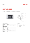
Frame
The K-Series frame is available in aluminium, titanium and carbon. Aluminium and titanium frames come
with frame angles of 75° and 90°; carbon frames come with a frame angle of 75°. Furthermore, the 75° and
the 90° aluminium frames come with adduction and in a short, respective +5 version.
Front seat height
(SHv) in mm
(with a 24” rear
wheel)*
Lower leg length
(UL) with standardmounted bar
Lower leg length (UL) with
standard-mounted fold-up
footrest
Seat depth
(ST)
75° short
450 to 470
SHv -120** to SHv -30
SHv -160** to SHv -30
375 to 450
75° standard
480 to 500
SHv -110** to SHv -30
SHv -150** to SHv -30
375 to 450
75°+5
500 to 520
SHv -110** to SHv -30
SHv -150** to SHv -30
450 to 525
90° short
450 to 470
SHv -140** to SHv -40
SHv -180** to SHv -40
375 to 450
90° standard
480 to 500
SHv -130** to SHv -40
SHv -170** to SHv -40
375 to 450
90°+5
500 to 520
SHv -130** to SHv -40
SHv -170** to SHv -40
450 to 525
75° adduction
480 to 500
SHv -110** to SHv -30
SHv -150** to SHv -30
375 to 450
90° adduction
480 to 500
SHv -130** to SHv -40
SHv -170** to SHv -40
375 to 450
75° standard
480 to 500
SHv -110** to SHv -30
SHv -150** to SHv -30
375 to 450
90° standard
480 to 500
SHv -130** to SHv -40
SHv -170** to SHv -40
375 to 450
75° standard
490 to 500
SHv -110** to SHv -30
SHv -150** to SHv -30
375 to 450
Carbon
Titanium
Aluminium
Frame
*With a 25” rear wheel, the SHv is 10 mm greater in each case. With a 26” rear wheel, the SHv is 20 mm greater
in each case.
**With a 25” rear wheel, deduct 10 mm in each case when calculating the lower leg length. With a 26” rear
wheel, deduct 20 mm in each case from the SHv (see examples in the following Table).
Examples:
Frame
SHv in mm
Lower leg length
(UL) with standardmounted bar
Lower leg length with standardmounted fold-up footrest
75° short, 25” rear wheel
460 to 480
SHv -130 to SHv -30
SHv -170 to SHv -30
75° short, 26” rear wheel
470 to 480
SHv -140 to SHv -30
SHv -180 to SHv -30
For lower leg lengths, the high-mounted footrest must be used. Æ Chapter: Footrests, ‹Assembling and
adjusting high-mounted footrests›
6
© Küschall AG, Schweiz | 2010-11
Service manual
Seat
Seat
Seat width (SB)
Available seat widths: SB 340 to 480 in 20 mm steps.
Changing the seat width is very complicated. The seat module, the backrest, the real wheel axles and the
footrest have to be replaced.
Seat depth (ST)
Available seat depths: ST 375 to 525 in 25 mm steps.
Changing the seat depth requires the replacement of the complete seat module including the seat cover
and the seat rail and potentially also the seat cushion.
Front seat height (SHv)
The front seat height is dependent on several factors that interact with each other. The size of the rear
wheels determines the height of the sub-structure. In addition to the size and the positioning of the
brackets on the seat module, the frame, seat depth and rear seat height influence the seat height.
24''
25''
26''
90° / 90°+5
7
90°short
A
B
C
3''
4''
5''
75° / 75°+5
D
E
75°short
F
© Küschall AG, Schweiz | 2010-11
Service manual
Seat
Possible front and rear wheel combinations
Rear wheel
Frame
24‘‘
25‘‘
3''
4''
5''
75° short
F
E
75° / 75°+5 / 90°short
D
C
B
90° / 90°+5
B
A
--
D
75° short
--
F
E
75° / 75° +5 / 90°short
E
D
C
90° / 90°+5
C
B
--
26‘‘
75° / 75° +5
F
E
D
90° / 90°+5
D
C
B
L is straight and the front wheel supports are perpendicular to the
Only select combinations listed in the Table to ensure that the frame
ground.
1cm
If the rear wheel, front wheel and front wheel fork are defined, the front seat
height can be adjusted by changing the position of the seat module within
the frame. There are 2 brackets available, each with 2 fixing options.
Positioning or replacing the brackets at the front for setting
the front seat height (SHv)
Tools: ¥ 4, 5
Difficulty: zzz
6
Remove the rear wheels, fold the backrest forward and place the
wheelchair on its back.
Loosen the screws c and d that connect the seat brace e to the seat
module or the frame on both sides.
2
1
Remove the screw g and place it in the bracket’s f other hole.
3
If you require a new bracket, remove the screws g and h, replace the
bracket f and fix it using the screws g and h.
4
5
Refit the rear wheels, stand the wheelchair back up and check the
position of the seat braces e. They should be as perpendicular to the
ground as possible.
Tighten the screw connections c and d of the seat braces and g and
h of the front brackets again.
Carry out the same setting on both sides.
c Æ 7 Nm
d Æ 13 Nm
g Æ 7 Nm
h Æ 7 Nm
L to the seat angle. It may be necessary to correspondingly adjust the
Note: ensure that adjusting the front seat height results in a change
rear seat height (SHh) or the backrest angle.
8
© Küschall AG, Schweiz | 2010-11
Service manual
Seat
Rear seat height (SHh)
The seat braces can be repositioned to adjust the rear seat height. The seat
braces are available in three different sizes, covering seat heights of between
380 and 490 mm.
Generally, we recommend fixing the seat braces to the lower hole on the
frame.
Rear seat height based on wheel position and wheel size
SHr
24”
wheel
25”
wheel
26”
wheel
S M L
S M L
S M L
12
11
380 1
8
7
390 1
1
400 2
1
1
410 3 5a
2
1
420 4 5
3 5a
2
430
6
4 5
3 5a
440
7 9a
6
4 5
450
8 9
7 9a
6
460
10
8 9
7 9a
10a
9a
8a
7a
6a
5a
2
1
470
11
10
8 9
480
12
11
10
12
11
490
6
5
4
3
12a
11a
10
9
S
M
L
Adjusting the rear seat height (SHh)
Tools: ¥ 5
Difficulty: zzz
Remove the rear wheels, fold the backrest forward and place the
wheelchair on its back.
Loosen the screw c for the front bracket on both sides.
If you can set the desired seat height using the existing seat brace d,
loosen the screw e and remove the screw f and the connecting
bar g.
If you require a new seat brace, remove the existing one and the
connecting bar g and loosely fix the new seat brace to the frame using
screw e.
Slide the seat brace against the rear bracket so that the required holes
overlap.
5
4
1
2
3
c Æ 7 Nm
e Æ 13 Nm
Insert the connecting bar g and fix it with screw f.
f Æ 7 Nm
Carry out the same setting on both sides.
Refit the rear wheels, stand the wheelchair back up and check the
position of the seat brace e. It should be as perpendicular to the
ground as possible.
Tighten the screws c, e and f.
L to the seat angle. It may be necessary to correspondingly adjust the
Note: ensure that adjusting the rear seat height results in a change
front seat height (SHv) or the backrest angle.
Seat angle (SW)
The seat angle is determined by the difference between the rear seat height
(SHh) and the front seat height (SHv).
9
© Küschall AG, Schweiz | 2010-11
Service manual
Seat
Tipping point adjustment
The tipping point of the wheelchair can be adjusted by changing the horizontal position of the seat module.
4
7
Tools: ¥ 4, 5
Difficulty: zzz
5
Remove the rear wheels, fold the backrest forward and place the
3
1
wheelchair on its back.
2
7
Loosen the screws c, d and g.
Remove the screws e and f and slide the seat module forwards or
c Æ 7 Nm
backwards.
d Æ 7 Nm
Fix the seat module with the screws e and f and tighten the screws
c, d and g again.
e Æ 7 Nm
Carry out the same setting on both sides.
f Æ 7 Nm
There are 3 possible positions for the rear bracket and 5 possible positions
for the front bracket.
g Æ 13 Nm
Note: ensure that the seat brace i is as vertical as possible following
L an adjustment.
2
Suspension
3
A suspension can be fitted for a SHh of between 380 and 460.
1
Fitting a suspension
Tools: ¥ 4, 5
Difficulty: zzz
Remove the rear wheels, fold the backrest forward and place the
wheelchair on its back.
Remove the seat module by removing the brackets at the front c and
5
the rear d.
Removing the seat brace e.
4
Fit the suspension housing f to the frame. Here, slide the screw with
the washer g through the suspension housing and place the lubricated
sleeve with the spacer elements on the screw. Slide the screw g
through the frame into the axle holder stay and tighten it firmly.
6
8
Function check:
It should be possible to rotate the suspension housing f, but it must not be
loose.
4
Insert the suspension seat strut h from above into the suspension
g Æ 7 Nm
7
housing f. Slide the sleeve i from below over the suspension seat
strut h and position it at the desired seat height. Fix it using the screw
and the washer j.
j Æ 4 Nm
9
Carry out the same setting on both sides.
D Æ 7 Nm
10
F Æ 7 Nm
Lubricate the springs k and insert them into the suspension
housing f. Insert the screws l into the suspension housing until they
protrude by 25 mm.
Fix the front and rear spring brackets to the seat module (screws D),
13
12
11
6
insert the lubricated rotating sleeves E and fix the seat module to the
frame (screws F) again.
Reattach the wheels and stand the wheelchair up again.
Check:
Check the front seat height. When fitting the mudguard, ensure that it is at
least 4 mm from the wheel. Check the suspension function.
10
12
13
© Küschall AG, Schweiz | 2010-11
Service manual
Backrest
Backrest
The adjustable back is fitted with velcro bands and a cover. Apart from the
adjustable back there is the light cover, which is produced individually for
each backrest height (RH) and seat width (SB).
Backrest height (RH) to cover, backrest tube, pushhandles and bands
cover
backrest
tubel
pushhandle c
telescopic tube
straight d
bands above
stabilizing bar
270
S
S
S
1-band i
285
S
S
S
1-band i
300
S
S
S
1-band i
315
S
L
S
1-band i
330
S
L
S
2-bands j
345
M
L
S
2-bands j
360
M
L
S
2-bands j
375
M
L
S
2-bands+1-band
390
M
L
L
2-bands+1-band
405
M
L
L
2-bands+1-band
420
L
L
L
2-bands+1-band
435
L
L
L
4-bands k
450
L
L
L
4-bands k
465
L
L
L
4-bands k
480
L
L
L
4-bands k
top
band
10 cm backrestband, 2 parts g
RH
standard pushhandles c
foldable pushhandles d
4
3
2
1
5
7
8
9
Backrest height (RH) to pushhandles, telescopic tubes and bands
height adjustable pushhandles,
rearset f
bands above
stabilizing bar
top
band
telescopic tube
bended e
bands above
stabilizing bar
top
band
1-band i
S
1-band i
285
1-band i
S
1-band i
300
1-band i
S
1-band i
315
1-band i
S
1-band i
330
2-bands j
S
1-band i
345
2-bands j
S
1-band i
360
2-bands j
S
2-bands j
375
2-bands+1-band
M
2-bands j
390
2-bands+1-band
M
2-bands j
405
2-bands+1-band
M
2-bands j
420
2-bands+1-band
M
2-bands+1-band
435
4-bands k
L
2-bands+1-band
450
4-bands k
L
2-bands+1-band
465
4-bands k
L
2x2-bands j
480
4-bands k
L
2x2-bands j
endband, 10 cm h
270
10
6
8
7
endband, 10 cm h
RH
end band,
5 cm h
without pushhandles e
A 1-band strap i is placed beneath the stabilizing bar if there is a clothesguard, and a 2-bands strap j if there is a mudguard
11
© Küschall AG, Schweiz | 2010-11
Service manual
Backrest
Backrest height (RH)
The height of the backrest can be adjusted by moving the backrest tube.
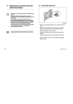
Adjusting the backrest height
Readjusting the push handle/telescopic tube
Difficulty: z{{
Tools: ¥ 3
8
Remove the backrest padding.
Remove the screw connection c and adjust the desired height of the
push handle or the telescopic tube. Insert the screw connection c
again and tighten the nut.
Carry out the same setting on both sides.
Refit the backrest padding.
L telescopic tube or push handle.
If the desired height cannot be achieved, you must use a different
1
c Æ 7 Nm
12
© Küschall AG, Schweiz | 2010-11
Service manual
Backrest
Replacing the backrest tube
Difficulty: z{{
Tools: ¥ 3,4
8, 10
Remove the backrest padding.
Slide the backrest bands upwards or downwards to gain access to the
screws c. Remove the screws and nuts on both sides
Remove the push handles or the telescopic tubes and remove the
upper Velcro® bands
1
Remove the screws d on the backrest joint.
Remove the lower Velcro® bands and the sleeve f with the adjustment
2
screwg from the backrest tube e and fit both to the new backrest
tube.
Fit the backrest tube to the backrest joint with the screws d. Here, first
fit the lower screw followed by the upper screw.
Fit the upper Velcro® bands and the push handles or the telescopic
tubes again and fix them with screws c and nuts.
Carry out the same setting on both sides.
3
Refit the backrest padding.
c Æ 7 Nm
M
d Æ 7 Nm
The excentre plates must be adjusted identically on both sides of the
wheelchair. Æ ‹Adjusting the backrest angle›
h Æ 7 Nm
Check:
Check the settings of the adjustment screws g on both sides. The screw
head should only lightly touch the seat module when the backrest is in the
upright position. If necessary, readjust the length by releasing the counter
nut and tightening or loosening the adjustment screw. Then retighten the
counter nut h.
M backrest joint’s mechanism. Æ ‹Adjusting the backrest joint›
Incorrectly adjusted adjustment screws result in damage to the
13
4
5
6
© Küschall AG, Schweiz | 2010-11
Service manual
Backrest
Replacing the handle
An adhesive (e.g. hair spray) is used in these instructions. When applied to
the handle, this substance works as a lubricant and as an adhesive once dry.
M of 750 N. If in doubt, contact Küschall AG.
After drying, the adhesive used must be able to resist a pull-off force
Difficulty: zz{
Remove the old handle.
Remove any residue (residual adhesive, grease, dust) from the push
handle tube.
Apply a thin layer of hair spray all over the surface of the push handle
tube onto which the handle is to be slid.
Apply a thin layer of hair spray to the inside of the handle.
Slide the new handle onto the push handle tube.
Move the handle into the correct position (grooves facing upwards).
L one, the push handle tube must be shortened by 35 mm. The push
If a long handle has been fitted and this is to be replaced with a short
handle tube must be replaced when switching from a short to a long
handle.
Replacing foldable push handles
Difficulty: z{{
Tools: ¥4
Remove the old foldable push handle and the old threaded sleeve.
3
Slide the new threaded sleeve c onto the telescopic tube d.
M and that the old sleeve is not left in, and reused for, the telescopic
For safety reasons, it is important that a new threaded sleeve is used
1
4
tube.
Slide the new foldable push handle e onto the telescopic tube d.
2
Fix the foldable push handle with the screw f.
L not been fitted and a foldable push handle is to be newly fitted.
The telescopic tube must be replaced if a foldable push handle has
14
f Æ 7 Nm
© Küschall AG, Schweiz | 2010-11
Service manual
Backrest
Backrest angle (RW)
The angle of the backrest can be changed by repositioning the excentre
plate in the backrest joint plate.
The following angles (measured from the seat) can be set:
90°
Adjusting the backrest angle
Difficulty: zz{
78
°
90
°
Tools: ¥ 3,
74
°
82
°
82
°
78
°
82
°
82
°
78
°
90
°
86
°
86
°
86
°
74
°
82
°
82
°
78
°
74
°
82
°
82
°
78
°
74
°
86°
90
°
90
°
86
°
90
°
82
°
82
°
82°
74
°
78°
86
°
74°
10
1
Fold down the backrest and release the counter nut of the adjustment
screw c and screw it in completely.
Remove the screw d on the excentre plate e. Remove the excentre
plate e and reinsert it in the desired position.
4
Reinsert the screw d and tighten it.
Fold the backrest up until the stop bolts f engage and unscrew the
5
adjustment screw c until it touches the frame and the backrest joint
no longer moves.
1
2
Tighten the counter nut g.
M wheelchair.
The excentre plates must be set identically on both sides of the
3
d Æ 4 Nm
g Æ 7 Nm
4
Adjusting the backrest joint
Difficulty: zz{
Tools: 10
Put the backrest up and let the pin c engage.
Press the backrest forwards to ensure the joint cannot move.
Unscrew the screw e until it touches the spigot f of the seat frame.
5
3
Screw the screw back in by between a ¼ and a ½ turn and counter with
the counter nut g.
3
4
g Æ 7 Nm
2
Correctly adjust the backrest joint on both sides.
1
Function check:
Sit in the wheelchair and lean back so that the backrest is strained. Upon
pulling the release cord d, the pin c must be easily removed on both
sides and must fully glide back in upon letting go of the release cord.
15
© Küschall AG, Schweiz | 2010-11
Service manual
Footrests
Footrests
The footrest must be selected in accordance with the seat width. A standard
footrest and an angle-adjustable footrest are available. Furthermore, there is
a choice between a high-mounted footrest and a fold-up footrest.
Lower leg length (UL)
To change the lower leg length, the footrest can be fixed at a higher or lower
position. Æ Chapter: Frame, Table). The shortest lower leg lengths can be
achieved using the high-mounted footrest. Æ ‹Fitting and adjusting highmounted footrest›
1
Replacing footrests
Difficulty: z{{
Tools: ¥ 4
8
Remove the screw connections c on both sides.
Remove the footrest and replace it with a new one.
Tighten the screw connections c on both sides.
Carry out the same setting on both sides.
c Æ 4 Nm
Adjusting the footrest height
Difficulty: z{{
Tools: ¥ 4
8
The height of the footrest can be adjusted in 1-cm steps.
Remove the screw connections c on both sides.
1
Slide the footplate to the desired height.
Tighten the screw connections c on both sides.
c Æ 4 Nm
Carry out the same setting on both sides.
L footrest must be used Æ ‹Fitting and adjusting a high-mounted
If the desired lower leg length cannot be achieved, a high-mounted
footrest›
16
© Küschall AG, Schweiz | 2010-11
Service manual
Footrests
Fitting and adjusting high-mounted footrest
Difficulty: z{{
Tools: ¥ 4, 5
3
8, 10
Fit the frame bar f for the high-mounted footrest to the front frame on
both sides using the screw connections c.
1
2
Fix the clamp set to both sides of the frame e using the screw
connection d. Only tighten lightly.
c Æ 7Nm
Slide the high-mounted footplate g into the clamp set and to the
desired height.
d Æ 7 Nm
4
Tighten the screw connections d on both sides.
5
Angle-adjustable footplate, adjusting the angle
Difficulty: z{{
Tools: ¥ 4
10
To adjust the angle, release the four screw connections c until the
footplate can be moved.
Check and/or adjust the distance between the left and the right sides
by pushing in or pulling out the tubes below the footplate in such a way
that the bearings blocks are perpendicular to the ground.
Tilt the footplate into the desired position and tighten the screw
connections c.
1
M slide off the plate.
The angle of the footplate must be set so that the user’s feet cannot
1
Fit fold-up footrest
Difficulty: zz{
c Æ 13 Nm
Tools: ¥ 4, 5
8, 10
Fix the reinforcing bar c to the frame and position it so that the
bearings blocks are perpendicular to the ground. Then, firmly tighten
the screw connection d.
On both sides, slide the telescopic tubes f into the frame. On both
sides, fix the telescopic tubes at the desired height using the screw
connection e.
1
Carry out the same setting on both sides.
Insert the sleeve g into the mounting part h of the right telescopic
tube. Fix it using the screw i.
9
2
Place the left tube of the footplate j into the mounting part on both
sides of the left telescopic tube, each with a washer. Fix it using the
screw k.
Insert the right tube of the footplate into the mounting part of the right
telescopic tube. Adjust the distance between the left and the right sides
by pushing in or pulling out the tubes below the footplate in such a way
that the bearings blocks are perpendicular to the ground.
Tilt the footplate into the desired position and tighten the footplate
screws. Æ ‹Angle-adjustable footplate, adjusting the angle›
8
3
4
d Æ 7 Nm
5
6
7
e Æ 7 Nm
i Æ 7 Nm
k Æ 7 Nm
L tube fixed, left tube moving).
The footrest can also be fitted the other way around (right footrest
17
© Küschall AG, Schweiz | 2010-11
Service manual
Side parts
Side parts
Armrest
The clothes-guard fitted as standard can be augmented with an armrest.
2
Fitting and adjusting an armrest
Difficulty: zz{
Tools: ¥ 3, 4, 5
8, 10
Fold the backrest forwards.
Remove the backrest spigotsc and replace them with the armrest
holders on both sides d.
Fit the connecting tube on both sides using the screws e.
1
To adjust the height as required, position the sleeve f in the tube so
e Æ 7 Nm
that the screw connection g can be fixed to the appropriate hole in the
tube. Place the armrest in the holder.
g Æ 7 Nm
Set the desired armrest height on both sides.
3
5
4
Fitting and adjusting a height-adjustable armrest
Difficulty: zz{
2
Tools: ¥ 4, 5 ´ 2
Fit the holder c and the bracket d to the seat module on both sides.
4
Tighten the screws e only lightly.
Fit the bar f between the two brackets d using the screws g. Tighten
the screws e.
5
2
1
To adjust the armrest height, insert the armrest h into the holder c.
3
Loosen the screws i for the height adjustment and slide it into the
6
desired position.
Then retighten the screws i for the height adjustment.
e Æ 7 Nm
By tightening or loosening the screws j, you can adjust how easily the
g Æ 7 Nm
armrest can be pulled out or pushed in.
i Æ 4 Nm
7
8
1
18
© Küschall AG, Schweiz | 2010-11
Service manual
Side parts
Clothes-guard/mudguard
The clothes-guard fitted as standard can be replaced by a mudguard.
Clothes-guard/mudguard size
Wheel size
SHh
24‘‘
25‘‘
26‘‘
38
L
—
—
39
L
L
—
40
L
L
L
41
L
L
L
42
L
L
L
43
M
L
L
44
M
L
L
45
M
L
L
46
M
L
L
47
M
M
L
48
M
M
L
49
M
M
L
L
Replacing the clothes-guard
The mounting element c on the backrest should already be fitted.
Difficulty: zz{
Tools: ¥ 3, 4
1
If present, remove the clothes-guard to be replaced by loosening the
screw connection e .
3
Check the correct position of the clothes-guard d with fitted rear
wheel. Here, find the suitable height on the clothes-guard d for fixing
the screw connection e to the backrest mount c.
If necessary, the holder f on the seat module can be replaced. Here,
remove the screw g.
2
e Æ 4 Nm
L the seat module and the holder and the upper edge runs above the
The clothes-guard is correctly positioned if it can be inserted between
g Æ 7 Nm
rear wheel.
4
5
19
© Küschall AG, Schweiz | 2010-11
Service manual
Side parts
Fitting the mudguard
Difficulty: zz{
Tools: ¥ 3, 4
10 ´ 2
Remove the clothes-guard and the mounting elements on the backrest and
the seat.
Fit the holder to the seat module using the screw connections c and
then refit the rear wheel.
Slightly loosen the screws d on the adjustment plate and slide it along
the mudguard carrier until the mudguard is at the right height.
The position of the mudguard can also be adjusted: Here, loosen the
screw connections e and f, position the mudguard as required and
tighten the screw connections e and f again.
c Æ 7 Nm
d Æ 4 Nm
e Æ 7 Nm
f Æ 7 Nm
Tighten the screws d again.
1
Carry out the same setting on both sides.
4
By tightening or loosening the screws g you can adjust how easily the
armrest can be pulled out or pushed in.
3
L between the mudguard and the wheel must be at least 4 cm.
The existing axle may not be sufficiently long for the new
L configuration with mudguard. In this case, a longer axle must be
2
If the wheelchair is equipped with a suspension, the distance
fitted. Æ ‹Changing the wheel chamber / fitting and adjusting an
axle›
M either < 8 mm or > 25 mm to prevent fingers from becoming caught
The distance between the mudguard and the wheel must be
5
between the wheel and the mudguard.
20
© Küschall AG, Schweiz | 2010-11
Service manual
Front wheels
Front wheels
Replacing a front wheel
Difficulty: z{{
Tools: ¥ 2x3
Remove the screw c with disk on one side. Remove the wheel axle d.
Remove the front wheel e.
Place the sleeves f between the new front wheel e and the fork.
Slide the axle d through the fork, sleeves f and the front wheel e and
2
fix the axle using the screw c. Here, use the new screw supplied with
the wheel as this screw comes with a thread-locking device.
1
4
3
Function check:
The wheel must not wobble, but must rotate easily.
4
1
Replacing a front wheel fork
Difficulty: zz{
Tools:
c Æ 4 Nm
1
2
5
10
4
Remove the sealing cap c of the bearings block by inserting two
screwdrivers into the grooves and flipping it off.
Remove the nut d with the washer g.
Remove the front wheel fork e.
4
Check the ball bearings f and replace them if necessary.
Insert the new front wheel fork with the washer g and the nut d and
3
tighten the nut.
Carry out the function check (see below).
Replace the sealing cap c.
Function check:
Tip the wheelchair backwards by 90° so that it is lying on the backrest and
the rear wheels. Turn the fork upwards (position A) and let it tip downwards.
A
The fork has been correctly adjusted if it easily turns to beyond the
bottommost point and remains there (position B).
If the fork turns back to the lower position (position C), it has not been
sufficiently tightened. There is a risk that the front wheels will start to
wobble at high speeds.
B
C
21
© Küschall AG, Schweiz | 2010-11
Service manual
Rear wheels
Rear wheels
Ensuring the rear wheels are parallel
Tools: ¥ 5
Difficulty: zz{
Loosen the screws c on both clamp sets. Rotate the axle tube to set
the correct position.
Tighten the screw c on both sides.
c Æ 13 Nm
L the rear wheels is correct if the distance between the rear wheels is
This setting must be carried out on a horizontal surface. The track of
1
the same at the front and the back (x=y) – measured at the height of
the centre of the axle.
Adjusting the removable axle
2
Difficulty: zz{
Tools: 11, 19
Remove the rear wheel.
Hold the end of the removable axle d using the straddle spanner.
Adjust the length of the removable axle by turning the nut c. The
length is correctly adjusted if the removable axle engages correctly
when fixing the wheel and wheel has just minimal clearance.
L The adjustment must now be checked or carried out again to ensure
The wheels must be replaced after adjusting both removable axles.
1
the wheels can be switched.
Fitting and adjusting a rear wheel extension
Difficulty: zz{
Tools: ¥ 3, 4, 5
8
Remove the screw c on both sides and remove the axle holder d with
the axle.
Remove the screws e and the screw connections f on both sides and
4
1
remove the axle holder.
Fit the axle locking ring g to the desired hole in the rear wheel
2
extension i using the screws h. Here, do not yet tighten the screws.
Slide the two rear wheel extensions onto the axle.
3
L fitted.
The corresponding locking ring must be used if a Vario-Ax is being
Fit the rear wheel extension to both sides of the wheelchair using the
screw c.
8
5
6
Ensuring the rear wheels are parallel. Æ ‹Ensuring the rear wheels are
7
parallel›
Tighten the screw j on the axle locking ring on both sides to fix the
axle.
Tighten the screws h on both sides.
c Æ 13 Nm
h Æ 7 Nm
1
1
j Æ 7 Nm
22
© Küschall AG, Schweiz | 2010-11
Service manual
Rear wheels
Changing the wheel chamber / Fitting and
adjusting an axle
Standard axle
Tools: ¥ 5
Difficulty: zz{
2
A new axle must be used to change the wheel chamber.
1
Remove the screws c on both sides and open up the lower part of the
axle holder d.
Replace the axle e with a new axle with the desired wheel chamber.
3
Open the lower part of the axle holder d on both sides and insert the
screw c.
Ensure the rear wheels are parallel.
‹Ensuring the rear wheels are parallel›
2
Tighten the screws c on both sides.
1
c Æ 13 Nm
Fitting Vario Ax
Difficulty: zz{
Tools: ¥ 3, 5
8
1
Remove the screws c on both sides and remove the axle holder with
the axle.
1
Fit the upper part of the Vario Ax holder d on both sides using the
screw c.
Insert the Vario Ax e and fit the lower part of the Vario Ax holder f on
1
both sides using the screw connections g and h.
Set the desired wheel chamber. ‹Adjusting the Vario Ax›
2
Ensure the rear wheels are parallel for wheel chamber 3° or 7°.
c Æ 13 Nm
‹Ensuring the rear wheels are parallel›
g Æ 4 Nm
5
Tighten the screws h on both sides.
h Æ 13 Nm
3
4
6
Adjusting the Vario Ax
Difficulty: zz{
Tools:
Loosen the knurled screw c on the Vario Ax.
Pull the rear wheel by the wheel hub d until the desired wheel
chamber is set. Possible settings are 1, 3, 7 and 10 degrees.
1
Tighten the knurled screw c again (not too tight).
2
23
© Küschall AG, Schweiz | 2010-11
Service manual
Brakes
Brakes
Fitting / adjusting the parking brake
Difficulty: zz{
Tools: ¥ 5
M changing the wheel chamber) must be readjusted.
The parking brake function is only guaranteed if the tire has the
M corresponding air pressure.
2
Following each positioning, the rear wheel parking brakes (e.g. when
Check that the rear wheels have sufficient air.
1
2
3
Loosely fix the clamping piece d to the frame with the screw c.
Slide the brake e into the correct position and tighten the screw c.
c Æ 13 Nm
4
L
Furthermore, please note that very little force is required for
L activating and deactivating the brake. If necessary, a brake lever
When the brake is on, the brake shoe f should press approx. 4 mm
into the tire.
extension can be fitted.
Visual check
Check that the parking brake is correctly positioned. The brake is correctly
adjusted if the brake shoe does not press more than 4 mm into the tire when
the brake is on.
Function check
Place the loaded wheelchair on a ramp with a 7° slope with the parking
brake on. The wheelchair must not move. Carry out this check with the
wheelchair both facing down the ramp and facing up the ramp.
24
© Küschall AG, Schweiz | 2010-11
Service manual
Options & accessories
Options & accessories
Antitipper
There are two different sizes of antitipper for both the left and the right
sides.
Fit antitipper without rear wheel extension
Difficulty: zz{
Tools: ¥ 3, 5
8
3
2
Loosen the screw c and the screw connection d and remove the
1
lower part of the axle holder e.
Fix the adaptation holder clip f with the screw connection d and the
screw c .
c Æ 13 Nm
Check that the rear wheels are parallel. Chapter: Rear wheels;
1
2
‹Ensuring the rear wheels are parallel›
Fix the antitipper to the adaptation holder f using the threaded
d Æ 4 Nm
h Æ 13 Nm
4
sleeves g and the screws h. Measure the distance between the
antitipper and the ground. ‹Adjusting the height of the antitipper›
7
4
5
6
Fit antitipper with rear wheel extension
Difficulty: zz{
Tools: ¥ 5
3
10
2
The adaptation holder must be fixed to the rear-most position/between the
double axles.
Fix the adaptation holder c to the rear wheel extension f using the
4
1
spacer sleeves d and the screw connections e.
L of 6.1 mm.
It may be necessary to widen the existing holes to a diameter
6
3
5
Using the screw connections h fix the antitipper to the adaptation
holder c. Measure the distance between the antitipper and the
ground. ‹Adjusting the height of the antitipper›
7
1
6
e Æ 13 Nm
h Æ 13 Nm
Adjusting the height of the antitipper
Press the adjustment button i on the antitipper and pull the antitip
tube into the desired position. Let the adjustment button latch into the
adjacent hole.
Function check:
The distance between the antitipper and the ground should be 4-6 cm. It
should be easy to fold up the antitipper.
Tip the wheelchair backwards using the antitipper until the axle is
perpendicular to the antitipper’s point of contact with the ground. In this
position, the distance between the rear wheel and the ground must be at
least 5 cm.
x
x 50 mm
25
© Küschall AG, Schweiz | 2010-11
Service manual
Options & accessories
Active antitipper
Fitting and adjusting an active antitipper
Difficulty: zzz
Tools: ¥ 3, 5
8
Fit the holder c to the axle tube. Here, only lightly tighten the
2
screws d.
5
Remove the QuickPin e, slide the active antitipper over the holder and
1
reinsert the QuickPin.
Turn the antitipper so that it is the desired distance from the ground.
1
Carefully remove the antitipper so that the position of the holder c
d Æ 7 Nm
does not change.
3
g Æ 7 Nm
Tighten the screws d.
For the aluminium axle, not for the Vario axle: Once the holder c is
correctly positioned, drill into the axle from both sides through the
corresponding hole in the holder c and insert the screw connection g.
L
The active antitipper cannot be fitted to the carbon axle.
Transit wheels
Fitting and adjusting transit wheels
Difficulty: zz{
Tools: ¥ 3, 5
8
Loosen the screw c and the screw connection d and remove the lower
part of the axle holder e.
Fix the adaptation holder clip f with the screw connection d and the
screw c .
3
2
1
Check that the rear wheels are parallel. Chapter: Rear wheels;
‹Ensuring the rear wheels are parallel›
Fix the transit wheeli using the threaded sleeves g and the screws h
to the adaptation holder f.
Fit a transit wheel on both sides.
1
2
4
c Æ 13 Nm
d Æ 4 Nm
7
h Æ 13 Nm
4
5
6
26
© Küschall AG, Schweiz | 2010-11
Service manual
Options & accessories
27
© Küschall AG, Schweiz | 2010-11
Küschall AG
Benkenstrasse 260
CH-4108 Witterswil
[email protected]
www.kueschall.com
Service manual K-Series
ENGLISH | 2010-11
küschall® distributors
Belgium & Luxemburg:*OWBDBSFOWt"VUPCBBOt#-PQQFN
5FM
t'BY
tCFMHJVN!JOWBDBSFDPN
Danmark:*OWBDBSF"4t4ES3JOHWFKt%,#SOECZ
5FM
t'BY
tEFONBSL!JOWBDBSFDPN
Deutschland:*OWBDBSF"RVBUFD(NC)t"MFNBOOFOTUSBFt%*TOZ
5FM
t'BY
tJOGP!JOWBDBSFBRVBUFDDPN
Deutschland:6MSJDI"MCFS(NC)t7PSEFN8FJTTFO4UFJOt%"MCTUBEU5BJMöOHFO
5FM
t'BY
tJOGP!VMSJDIBMCFSEF
European Distributor Organisation:*OWBDBSFt,MFJTUTUSBFt%1PSUB8FTUGBMJDB
5FM
t'BY
tFEP!JOWBDBSFDPN
España:*OWBDBSF4"tD"SFOZTOt1PMÓHPO*OEVTUSJBMEF$FMSËt&$FMSË(JSPOB
5FM
t'BY
tDPOUBDUTQ!JOWBDBSFDPN
France:*OWBDBSF1PJSJFS4"4t3PVUFEF4U3PDIt''POEFUUFT
5FM
t'BY
tDPOUBDUGS!JOWBDBSFDPN
Ireland:*OWBDBSF*SFMBOE-UEt6OJU4FBUPXO#VTJOFTT$BNQVTt4FBUPXO3PBEt4XPSETt$PVOUZ%VCMJOo*SFMBOE
5FM
t'BY
tJSFMBOE!JOWBDBSFDPN
Italia:*OWBDBSF.FDD4BOTSMt7JBEFJ1JOJt*5IJFOF7*
5FM
t'BY
tJUBMJB!JOWBDBSFDPN
Nederland:*OWBDBSF#7t$FMTJVTTUSBBUt/-#;&EF
5FM
t'BY
tOFEFSMBOE!JOWBDBSFDPNtDTFEF!JOWBDBSFDPN
Norge:*OWBDBSF"4t(SFOTFTWJOHFOt1PTUCPLTt&UUFSTUBEt/0TMP
5FM
t'BY
tOPSXBZ!JOWBDBSFDPNtJTMBOE!JOWBDBSFDPN
Österreich:*OWBDBSF"VTUSJB(NC)t)FS[PH0EJMPTUSBTTFt".POETFF
5FM
t'BY
tJOGP!JOWBDBSFBVTUSJBDPN
Portugal:*OWBDBSF-EBt3VB&TUSBEB7FMIBtt1-FÎBEP#BMJP
5FM
t'BY
tQPSUVHBM!JOWBDBSFDPN
Sverige & Suomi:*OWBDBSF"#t'BHFSTUBHBUBOt44QÌOHB
5FM
t'BY
tTXFEFO!JOWBDBSFDPNtöOMBOE!JOWBDBSFDPN
Switzerland:*OWBDBSF"(t#FOLFOTUSBTTFt$)8JUUFSTXJM
5FM
t'BY
tTXJU[FSMBOE!JOWBDBSFDPN
United Kingdom:*OWBDBSF-JNJUFEt1FODPFE5FDIOPMPHZ1BSL
1FODPFE#SJEHFOE$');t4XJUDICPBSE5FM
'BY
t
$VTUPNFSTFSWJDFT5FM
t'BY
© Küschall AG, Schweiz | 2010-11