1
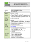
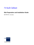
OWNERS AND SERVICE MANUAL
0 1994, INNOVATIVE CONCEPTS IN ENTERTAINMENT, INC.
1501 KENSINGTON AVENUE, BU.FFALO, NEW YORK 14215 PHONE 716-833-0481 FAX 716-833-1342
QUICK TROUBLESHOOTING
PROBLEM
~PROBABLE CAUSE
SOLUTION
NO CAME POWER
ON-OFF SWITCH ON GAME TURNED OFF
A.C. POWER FUSE BLOWN
CAME NOT PLUGGED IN OR CORD DAMAGED
BAD TRANSFORMER
TRANSFORMER HARNESS NOT CONNECTED
BAD POWER MODULE
TURN POWER ON
REPLACE WITH PROPER FUSE
CHECK POWER CORD
CHECK FOR PROPER VOLTAGES
CHECK HARNESS
REPLACE POWER MODULE
CAME WILL NOTTAKE MONEY OR
GIVE CREDITS CORRECTLY.
BAD COIN SWITCH
COIN DISCOUNTING OPTION SET WRONG
COINS PER CREDIT SETTING INCORRECT
BAD COIN MECHANISM
LOOSE OR DAMAGED HARNESSING
BAD MAIN P.C. BOARD
BAD 5 VOLT POWER SUPPLY FUSE
CHECK W/METER OR REPLACE
CHECK PROGRAMMABLE SElTlNC
CHECK PROGRAMMABLE SElTlNC
ADlUST OR REPLACE
CHECK W/METER - REPAIR
REPAIR OR REPLACE MAIN BOARD
CHECK AND REPLACE FUSE
TICKETS DO NOT DISPENSE OR
DISPENSE INCORRECTLY
ZONE VALUES SET UP INCORRECTLY
TICKET RESET BUlTON NOT PUSHED
TICKET DISPENSER OPTICAL SENSOR DIRTY
TICKET DISPENSER HARNESSING BAD
TICKET DISPENSER BAD
BAD MAIN P.C. BOARD
BAD 5 VOLT POWER SUPPLY FUSE
CHECK PROGRAMMABLE SElTINC
PRESS RESET BUlTON
CLEAN OPTICAL SENSOR
CHECK W/METER AND REPAIR
REPLACE DISPENSER
REPLACE MAIN P.C. BOARD
CHECK AND REPLACE FUSE
NEON BULBS DO NOT LIGHT
BAD NEON BULB
BAD NEON P.C. BOARD
BAD MAIN P.C. BOARD
BAD NEON POWER SUPPLY FUSE
BAD NEON HARNESSING
BAD 5 VOLT POWER SUPPLY FUSE
TEST BULB AND REPLACE
REPLACE NEON P.C. BOARD
REPLACE MAIN P.C. BOARD
CHECK AND REPLACE FUSE
CHECK W/METER AND REPAIR
CHECK AND REPLACE FUSE
RING LIGHT BULBS DO NOT LIGHT
BAD LIGHT BULB
BAD UCHT RING P.C. BOARD
BAD INTERCONNECT HARNESSING
BAD MAIN P.C. BOARD
LIGHT RING POWER SUPPLY FUSE BAD
BAD 5 VOLT POWER SUPPLY FUSE
REPLACE LIGHT BULB
REPLACE LIGHT RING P.C. BOARD
CHECK W/METER AND REPAIR
REPAIR OR REPLACE P.C. BOARD
CHECK AND REPL4CE FUSE
CHECK AND REPLACE FUSE
SCORE DISPLAYS DO NOT WORK
BAD 12 VOLT STATION FUSE
BAD 5 VOLT POWER SUPPLY FUSE
BAD SCORE DISPLAY P.C. BOARD
BAD MAIN P.C. BOARD
BAD SCORE DISPLAY HARNESSING
CHECK
CHECK
REPAIR
REPAIR
CHECK
JACKPOT LIGHT DOES NOT LIGHT
BAD 12 VOLT STATION FUSE
BAD 5 VOLT POWER SUPPLY FUSE
BAD SCORE DISPLAY P.C. BOARD
BAD MAIN P.C. BOARD
BAD SCORE DISPLAY HARNESSING
CHECK AND REPLACE FUSE
CHECKAND REPLACE FUSE
REPAIR OR REPLACE P.C. BOARD
REPAIR OR REPLACE P.C. BOARD
CHECK W/METER AND REPAIR
LOW ! NO TICKET INDICATOR
DOES NOT WORK
BAD INDICATOR LE.D.
L.E.D. INSTALLED BACKWARDS
STATION HARNESSING BAD
TICKET MICRO SWITCH BAD
MAIN P.C. BOARD BAD
REPLACE LE.D.
REVERSE L.E.D.
CHECK W/METER AND REPAIR
REPLACE MICRO SWITCH
REPAIR OR REPLACE P.C. BOARD
STORM STOPPER BUITON DOES
NOT STOP LIGHT
BAD BUTTON SWITCH
BAD HARNESSING
BAD MAIN P.C. BOARD
REPLACE SWITCH
CHECK W/METER AND REPAIR
REPAIR OR REPLACE P.C. BOARD
AND REPLACE FUSE
AND REPLACE FUSE
OR REPLACE P.C. BOARD
OR REPLACE P.C. BOARD
W/METER AND REPAIR
GAME REPAIR
WARNING: ALWAYS REMOVE
POWER TO THE GAME BEFORE
AT-I-EMPTINC ANY SERVICE,
UNLESS NEEDED FOR SPECIFIC
TESTING. FAILURE TO OBSERVE
THIS PRECAUTION COULD RESULT
IN SERIOUS INJURY TO YOURSELF
OR OTHERS.
OPERATIONAL
BACKGROUND
The CYCLONEn* coin operated amusement game
has been designed for an absolute minimum of
service. Special circuitry prolon s the life of the
ItIon, the neon
incandescent light bulbs, In adc?*
bulbs used have a life span measured in years.
The Main P.C. Board has been designed with 7
separate P.C. mounted power supplies, to
segregate different areas of the electronics. In
other words, if 1 station goes down, the other 2
stations will continue to work. If the sound goes
down, the rest of the game will continue to play,
etc. Additionally, the power supplies are all fan
forced cooled.
The Light Ring PI. Boards were designed to add
reliability to the game, by eliminating the
massive amount of wiring that would be needed
for the 84 light ring bulbs used. ihe light sockets
on the board were chosen to allow for the least
expensive bulbs possible to be used. The boards
were desi ned to change quickly and easily in
the unlike9y event that something would go
wrong with one of them.
TROUBLESHOOTING
PHILOSOPHY
When trying to find out if specific components
are bad or not, try swapping them with
components from another player station to see if
the problem moves with the component or stays
where it was. This will help you to know if you
have a problem with a specific compone:c or
maybe a problem with either the wiring or the
Main P.C. Board.
Use extreme caution when using probes or volt
meters if the game is powered up. If doing
continuity checks, it is important to disconnect
the harnessing at both ends, as attached they
may yield erroneous results.
If P.C. Boards are suspected as causing problems,
check to see that all of the I.C. chips are firmly
seated on the boards.
If light bulbs are suspected, swap them with one
that is known to work to narrow the problem
down to bulb or P.C. Board.
MAIN KC. BOARD
REPLACEMENT
1. Remove all A.C power from the game.
2. Carefully remove all of the connectors from the
P.C. Board.
3. Remove the 4 long hexagon nuts that secure
the board to the mounting bracket.
4. Gently pull the P.C. board from the mounting
bracket.
5. Re-in&II in the reverse order.
LIGHT RING P.C. BOARD
REPLACEMENT
N O T E: B E
E X T R E M E L Y CAREFUL NOT T O H I T
NEON BULB SOCKET FROM THE BOTTOM, AS
THEY ARE RELATIVELY FRAGILE.
A
1. Remove all A.C power to the game.
To find problems with the game, always first
check what should be obvious. See that the
game is plugged in, and that all of the fuses on
the game are good. This includes the fuse that is
located INSlqE the power module.
2. Remove the harnesses to the suspected bad
P.C. Board.
Nexf check to see that all of the connectors are
firmly seated, and that none of the wires have
pulled out of them.
4. Remove the 4 screws that hold the P.C. board
to the bottom of the playfield.
3. Remove the light bulbs from the bad board.
5. Re-assemble in reverse order.
GAME REPAI R
NEON BULB
REPLACEMENT
WARNING: NEON TRANSFORMERS EMIT HIGH
VOLTAGE.
BE CAREFUL WHEN SERVICING NEON TUBES AS
THEY ARE MADE OF CLASS AND ARE THEREFORE
VERY FRAGILE. ~~
3. Remove the 3,
six pin mate-lock connectors.
4. Remove the 6 single pin mate-lock connectors.
5. Remove the 4 corner screws that hold. the
neon board to the bottom of the playfield.
NOTE: THE 4 SCREWS ( IN THE CENTER OF EACH
SIDE OF THE BOARD) DO NOT COME OUT.
6. Re-assemble in reverse order. NOTE: BE SURE
THE BULBS LIGHT IN THE PROPER SEQUENCE.
BULB SEQUENCE
1. Remove all A.C. power to the game.
2. Remove the 2 single pin mate-lock connectors
that connect the bad bulb to the neon
transformer P.C. board.
3a. For “U” shaped bulbs, remove the 2 nuts that
secure the sockets to the playfield.
3b. For pie shaped neons, unsnap the neon from
the standoffs.
4. Remove the old neon and pull the wires up
through the mounting or access holes.
5. When re-assembling the”U” shaped neon
tubes, be sure to use the foam washer. I
INSTALL THE MOUNTING NUTS LOOSELY. THE
NEON SHOULD ROCK BACK AND FORTH
SLIGHTLY WHEN INSTALLED PROPERLY.
6. When re-assembling the pie shaped neons,
snap the neon into the standoffs evenly, the 2
closest to the outside first+ then the 2 closest to
the center.
7. Reconnect the wires to the neon transformer
P.C. board and test for proper operation.
NEON TRANSFORMER P.C.
BOARD REPIACEMENT
NOTE: BE CAREFUL WHEN SERVtClNC THE
NEON TRANSFORMER P.C. BOARD, AS THE
BOARD CONTAINS SMALL DIAMETER WIRES
THAT COULD BECOME BROKEN WITH ROUGH
HANDLING.
BEFORE REMOVING ANY CONNECTORS, NOTE
EXACTLY WHERE THEY WERE REMOVED FROM,
SO THE LIGHTS WILL LIGHT IN THE PROPER
SEQUENCE WHEN RE-INSTALLED.
1. Remove all A.C. power from the game.
2. Remove the Harnessing from the Main P.C.
Board with the mate-lock connectors.
1. The neon arches at the center of each jackpot
zone should alternately Rash on and off.
2. The neon arches between the 3 player stations
should remain lit
3. When the Jackpot is hit, the neons should
pulse from the far side of the game, to the
jackpot area.
4. The pie shaped neon should light only when
the ring light is lit in its zone.
CONTROL PANEL P.C.
BOARD REPLACEMENT
1. Remove all A.C. power to the game.
2. Remove the 2 mate-lock connectors to the P.C.
board.
3. Remove the 4 long hexagon nuts that hold the
board to the bottom of the control panel.
4. Carefully slide the board from the mounting
studs.
5. Re-assemble in the reverse order.
JACKPOT DISPLAY P.C.
BOARD REPLACEMENT
1. Remove all A.C. power to the game.
2. Remove the Dome.
3. Remove the 4 screws that hold the printed
filter on the Jackpot display housing.
4. Remove the 4 hexagon screws that hold the
Board to the housing, and remove the board.
5. Remove the mate-lock connectors.
6. Re-assemble in reverse order.
PARTS LISTINGS
MECHANICAL PARTS
cc1001
CC1 007
CC1 008
cc1009
cc1010
cc101 1
cc1012
cc101 3
cc1014
cc1015
CC1016
cc101 7
CC1018
cc1 019
cc1021
cc1 022
CC1023
CC1 024
cc1 025
CC1 026
CC1027
CC1 028
CC1 029
cc1 030
CC1 032
cc1033
cc1 034
cc1 035
CC1 036
cc1037
HI-l3001
CC3002X
cc3003
cc3004
cc3005
cc3007
cc301 0
cc301 1
CC301 2
cc301 3
cc301 4
cc301 5
Cabinet speaker panel
Main PC. Board mounting bracket
Cash box enclosure
Power module mounting plate
Top panel overlay (BLUE, LEFT)
Top panel overlay (BLUE, RIGHT)
Top panel overlay (BLUE, CENTER)
Top panel overlay (PINK LEFT)
Top panel overlay (PINK, RIGHT)
Top panel overlay (PINK, CENTER)
Top panel overlay (GREEN, LEFT)
Top panel overlay (GREEN, RIGHT)
Top panel overlay (GREEN, CENTER)
Scoreboard mounting bracket
Coin funnel mounting bracket
Cabinet door frame (BLUE)
Cabinet door frame (PINK)
Cabinet door frame (GREEN)
Cash door frame (BLUE)
Cash door frame (PINK)
Cash door frame (GREEN)
Cabinet coin door (BLUE)
Cabinet coin door (PINK)
Cabinet coin door (GREEN)
Cash box door (BLUE)
Cash box door (PINK)
Cash box door (GREEN)
Scoreboard housing (BLUE)
Scoreboard housing (PINK)
Scoreboard housing (GREEN)
Dome
Control panel assembly
Playfield’
Mirror
Mirror back (Melamine)
Power module enclosure
Cabinet bottom plate (Melamine)
Cabinet top plate (Melamine)
Plastic cash box
Coin funnel
Cabinet vertical member
Top plate support
2110
Transistor, TIP1 20
2117
\c 74HC14
2124
IC LM358
2237
IC 74HC4066 Bilateral Switch
2250
IC 74HC138
2253
ic 74HC374
2254
IC Audio amplifier TDA2002f-i
2262
IC 74HC174
IC 74HC237 Latching Output Decoder
2266
IC 74HCO0
2297
2299
IC 74HC373
IC 74HC165
2301
IC 74HC273
2305
Game Pm ram E-Prom
2320
2364
Heat sink 3an
2368
IC MC68HCllAl P Microprocessor
2411
IC LM78LOSACZ 5%V
2417
IC 74HC164
Bridge Rectifier 35Amp (wire leads)
2444
2519
6800uf Capacitor 25V radial
2520
68OOuf Capacitor 35V radial
2521
22OOOuf Capacitor 3SV radial
208004
IC ULN2003A Driver
IC LM338K Voltage Regulator
208009
Display MAN697 0
276
2518
Display, Dual 7 Segment
2523
IC LM307N OP Amp
PC20224 Counter 12 volt
PC20407 Battery - 3.2 volt (BR2032)
PC20435 IC LM340T-5 (7805) voltage regulator
cc2005x jackpot P.C. Board
cc202ox Neon Transformer P.C. Board
CC2032X Tickets Owed (control panel) P.C. Board
CC203 3X Jackpot Display P.C. Board
CC2034X Main P.C. Board
HARDWARE 61 MISC.
5014
PC6061 SA
FP1004
FP1019
FP2007
HH2027
ELECTRICAL / ELECTRONIC
PARTS
CC2001 Transformer, Neon
CC2002 Transformer, Game
CC7OOSX Storm stopper button
CC2006 Jackpot Ii ht (Housing &Amber cover)
CC2007 Inductor 4.6uH 1 .S amp neon choke
CC2008 Main P.C. Board heat sink
CC201 6 Neon arch socket nut (Plastic)
CC201 7 Neon Arch socket
CC201 8 Neon Arch (PINK)
CC201 9 Neon Arch (GREEN)
CC2020 Neon Arch (BLUE)
CC2021 Neon Triangle (PINK)
CC2022 Neon Triangle (GREEN)
CC2023 Neon Triangle (BLUE)
CC2335 Ring Board Bulb Socket
tight Ring Bulb (playfield) #906
2005
Jackpot light bulb #81
2061
Coin door lock
#2 Square Drive Bit
Leg leveler mounting bracket
Leveler Feet
Speaker
Power Cord
GRAPHICS
cc7001
CC7002
cc7004
cc7005
CC7006
cc7007
CC7008
cc701 1
cc701 2
cc701 3
cc701 4
cc9001
Cyclone - cabinet decal
By I.C.E. - decal
Control panel overlay
Storm Stopper - button decal
Scoreboard overlay
Programming decal
Fuse rating / power disconnect warning
Playfield zone decal - right
Playfield zone decal * left
Playfield JACKPOT decal
Alternate zone number decal sheet
Service Manual
I.C.E. warrants all components in the CYCLONE game, to be free o
defects in material and workmanship for a period of ninety days from the
date of purchase.
This warranty does not cover items damaged due to normal wear ant
tear, subjected to abuse, improperly assembled, modified, repaired, OI
operated in a fashion other that described in the service manual.
If your CYCLONE game fails to conform to the above mentionec
warranty, I.C.E.‘s sole liability shall be, at its’ option, to repair or replace
any defective component with a new or remanufactured component o
equal to or greater O.E.M. specification.
ICE. will assume no liability whatsoever, for costs associated with label
to replace defective parts, or travel time associated therein.
‘.C.E.‘s obli ation will be to ship free of charge, replacement parts by UPS
ground, U. 8 . Mail, or other comparable shipping means. Any Express
Mail or Overnight shipping expense is at the cost of the purchaser.
%ducts will be covered under the warranty only when:
1. The serial number of the game with the defective part is
given.
2. The serial number of the defective part, if applicable, is
given.
3. Defective parts are returned to I.C.E., shipping prepaid,
in a timely fashion, if requested by I.C.E.
4. A copy of the sales receipt is available as proof of
purchase upon request of I.C.E.
.C.E. distributors are independent, privately owned and operated. In their
udgment, they may sell parts or accessories other than those
nanufactured by I.C.E. We can not be responsible for the quality,
;uitability, or safety of any non-I.C.E. part, or any modification, including
abor, which is performed by such distributor.
TRANSFORMER CABLE
Pouer Connector
From Transformer
RED
BLU
BLU
RED
ORG
ORG
Pl
l(
18AC
2(
18W
3<
18AC
9<
5<
“<
18AC
18AC
18cIC
AMP 6 PIN
Cyclone Transformer Specifications
. . . . . . . . . . . . . .. . . . . . . . . . . . . . . . . . . . . . . . . . . . . . . . . . . . . . . . . . . . . . . . . . . . . . . . . . . . . . . . . . . . .
.
.
.
.
1oou
1
BLK
18GA
ou
1oou
WHT
2
3
BLK
18GA
OU
WHT
L+ 1
25u
18GA
5
BLKYWHT
ou
...........
5Q /
WHT/BLK
.............................................................
.
..
..
..
..
..
..
..
..
.
..
.
..
.
.
.
..
.
..
...
..
.
..
..
..
..
..
..
..
.
.
.
..
..
.
..
.
.
..
.
,.....
18UAC
18UAC
2A
+
Neon
5
&Lruu.
Neon 11
Neon 12
rLruu’
xrw
LlYP
LIl
115
II
LE
sic
IK
.LJ3
4
.Ils
r
43
T
-a
RI7
IK
Pl
- 3 .OO”
TABLE OF CONTENTS
l
INTRODUCTION
l
GAME SET UP /TESTING
l
MAINTENANCE
l
QUICK TROUBLESHOOTING
l
GAME REPAIR
l
PARTS LISTINGS
l
SCHEMATICS
0 WARANP/ INFORMATION
-
@:r
a----
-0-WY-
0
’0
D36 0
I
jo.1 0/
DP’
0 0
00 0
+
l
l ee:
l
l
l .
ee
ee
/keel
ieee,
ieee
/’
/’
/
ic
/ -
.“s.
.“c=.
\
0
0
p1
L,
\‘\ \
‘\
\,\
Ii!
I
I
-t
L
3 .OOO” -
1
.LJm
LJ
3
.A
0. .[_J.
.
l
.
%
l
0
.
l
l
Ml l
I -g
.[” .
:.Fl . r
l
:a
0,
.
.
l
.
0
:::
1.
em
:.,l
an
m
.
I
-
~
L
:
‘I0
1
g-g
-.
I
..Q
j
0
l
I
0
.
CD
-I
D
--4
0
D
w
r
rl
RINGCPU CABLE
,
Pl
13u > 1
CLK: > 5
DGNDl >
D(STAb > '5
LATCtil > 6
PGND >
AMP 6 PIN
FlMP 6 PIN
,
0
D
W
r
rl
DISPLAYS INTERCONNECT
:SMALL DISPLAY
P2
:DGND > ’
SJ > f
DATA > ~
IPGND > 5
12u >
CLK > 6
AMP 6 PIN
LClRGE DISPLAY
Pl
’ < DGND
2 < su
3 < DClTA
’ < PGND
5 < 12u
6 < CLK
MlP 6 PIN
~ Coin C o u n t e r H a r n e s s
No Connector This End
P8
CCNT > ;
12u >
INTRODUCTION
GAME FEATURES
This game has many outstanding features
making it the perfect game for just about any
location.
The game was designed with the location in
mind, featuring unparalleled flexibility in regards
to custom game set-up and programming.
Virtually all game play, and ticket dispensing
options are operator adjustable, practically
letting the operator “build his own game”.
CYCLONEnl has many unique features for a
“Ticket Spitter” type of game. Its Centerpiece
design sets it apart from all other games in this
category. Its Game Play, which is ALL SKILL,
having no bounces, rolls, flips, or other chancy
situations, also showcases its creative design.
These, and other features, give the players
something that keep them playing time and time
again.
Reliability - is the key word in the design of this
game. The electronics in the game have been
extensively tested to assure years of trouble free
service. The light ring light bulbs are powered
using special circuitryand voltages togreatly
enhance their life. The neon bulbs used should
last over the life of the game.
The cabinet has been designed using only the
finest materials available. The durable scratch
resistant painted surfaces will last for years. The
dome is made from LEXAN”*‘, an almost
indestructible material.
Game set-up is a snap. Just plug in, set a few
programmable options, and you’re ready to go.
Even the programming options are easy to
understand and adjust.
A “Tickets owed Display” is used for each station
to show tickets owed to the player. More on this
feature is given in the following game play
section.
GAME PLAY
The game begins when the player has inserted
enough money to create 1 “credit”.
The game has a ring of light bulbs encircling the
playfield. A lit bulb circles this ring every second
and a half. The object of the game is to stop the
light between two neon arches located in the
middle of your play zone.
Each light bulb in your zone has a
“ticket” value associated with it. As you get closer
to the 2 neon arches in the center of your zone,
the ticket value increases. Between the two neon
arches described above is the game JACKPOT.
This is where a large number of tickets can be
won.
Once the ame begins you have 1 chance to stop
the light (9or each credit inserted). Wherever the
light stops is how many tickets the game pays
out. Each time the Jackpot is NOT hit, the Jackpot
value increases by 1 or more tickets, (if the
incrementing Jackpot option is selected). When
the jackpot is hit, a Jackpot routine including
special lights and sounds is displayed.
Additional games can be played while tickerts are
dispensing.
The game also has a unique “Tickets Owed”
display. This display has many uses. When
tickets are won, the amount won are displayed,
and then counted down as the tickets are
dispensed. This is a handy feature in the event
that the game runs out of tickets while
dispensing, or if the game is out of tickets. If the
game cannot dispense the tickets it should, it will
keep adding the number it should dispense to
the tickets owed display, and thus allow the
player to continue playing the game until an
attendant can be contacted. This feature is also
very helpful if the “do not dispense tickets on
jackpot” option is chosen. It may be desireable
to NOT dispense tickets if the jackpot is set to a
very high number of tickets. This will be
valuable, as the number of Jackpot tickets won
would then be added to this display, then the
ticket dispenser will lock until an attendant is
located, and he resets the dispenser.
Station 1 [
!%a11
Displw
w
P7
P6
P9
PlO
Lame
Displw
f-l
P12
P3
Neon Board
P2
PI3
Tickot
1
i
\IY
I
m-c -
I
I
II
II
I, I
P3 +
bMna 1 PI
I
Jackpot 2
’
I.
Pl
PI -P3
PI
I
P2
PI
pi!-
huna 2
BMa3
P2
Jackpot 3
P I
I
m
I
PI
w
--i-’
-P3 h-luu Y
P2
I
Pl
Station 3
I
F
I
Station 2
I
I
I--
l
Neon Harness Cable
P7
NIR 9 Pin
P13
NIP 9 Pin
LIGHT RING INTERCONNECT
P2
FlHP 6 P I N
Pl
‘(
2(
3<
9<
5<
6<
9u
CLK
DGND
DATA
LATCH
PGND
AMP 6 PIN
J
I
-
GAME SET-UP / TESTING
SAFE-W
PRECAUTIONS
IMPORTANT: FAILURE TO FOLLOW
THESE DIRECTIONS CLOSELY COULD
CAUSE SERIOUS DAMAGE TO YOU OR
YOUR GAME.
rMARNINC: WHEN !NSTALL!NG TH!S
GAME, A 3 PRONG GROUNDED
RECEPTACLE MUST BE USED. FAILURE
TO DO SO COULD RESULT IN SERIOUS
INJURY TO YOURSELF OR OTHERS.
FAILURE TO USE A GROUNDED
RECEPTACLE COULD ALSO CAUSE
IMPROPER GAME OPERATION, OR
DAMAGE TO THE ELECTRONICS.
DO NOT DEFEAT OR REMOVE THE
GROUNDING PRONG ON THE POWER
CORD FOR THE SAME REASONS AS
GIVEN ABOVE. USING AN IMPROPERLY
GROUNDED GAME COULD VOID YOUR
WARRANTY.
PAY SPECIAL ATTENTION TO THE SET UP
SECTION BELOW, REGARDING VOLTAGE
5Ell-l NGS.
GAME SET-UP
BEFORE PLUGGING THE GAME IN, OR
TURNING IT ON, BE SURE THE GAME
HAS BEEN SETTO THE PROPER
VOLTAGE. YOUR GAME SHOULD COME
PRE-SET FROM THE FACTORY TO THE
CORRECT VOLTAGE, HOWEVER IT IS A
GOOD IDEA TO CHECK THE A.C. WALL
RECEPTACLE VOLTAGE BEFORE
PLUGGING THE GAME IN.
The game comes with 4 available voltage settings
as described below. These settings Should be
used to provide power in the correct range to
the game without over or under powering it
POWER RANGE
VOLTAGE SETTING
90 - 110 V.A.C.
llO- 130V.A.C.
110
120
200- 220 V.A.C.
220- 240 V.A.C.
220
240
The game uses a POWER MODULE to handle all
of the power distribution chores on the game. It
incorporates an ON-OFF switch, primary A.C.
game fusing, and power switching capabilities,
tar using~the game with a wide variety of A.C.
voltages by re-strapping the main transformer.
A.C. LINE VOLTAGE
ADJUSTMENT
To adjust the game for a different A.C. voltage:
1. Unplug the game from the outlet.
2. Disconnect the power cord from the
power module.
3. Using a small flat blade screwdriver,
pry the fuse holder from the power
module.
4. Notice a small window on the fuse
holder with an armw that points to
the voltage the game is presently set
at.
5. Using the small flat blade screwdriver,
lift the retaining tab that holds the
voltage selector in the fuse holder.
6. Rotate the voltage selector until the
voltage you want is displayed in the
voltage select window.
7. Push the voltage selector back into the
fuse holder until it snaps into place.
NOTE: Do not force the selector into
the fuse holder. If it does not go in
easily, it is not being installed
correctly.
8. Snap the fuse holder assembly back
into the power module.
9. Plug the power cord back into the
receptacle in the power module, and
into the wall outlet.
NOTE: WHEN CHANCING FROM 11 O-l 20 TO
220-240, LOWER THE MAIN FUSE VALUE BY l/2.
WHEN CHANCING FROM 220-240 TO 110-l 20,
DOUBLE THE MAIN FUSE VALUE.
GAME SET-UP / TESTING
PROGRAMMING
YOUR GAME
This section will give )ou a detailed explanation
on the functions and operating characteristics of
each of the programming buttons. Please read
this section carefully to avoid problems with your
game.
NOTE: THE PROGRAMMING BUTTONS SHOWN
BELOW MAY BE LOCATED EITHER ON THE MAIN
P.C. BOARD AS ILLUSTRATED, OR ON A
CONTROL BRACKET ATTACHED TO THE BLUE
ACCESS DOOR.
SW1
PROGRAMMING
BUITON
\
SW2
l w
___g&pL
0
’
,
i
y-7
$
I
SELECT BUTTON.
SWA
_._.
SELF TEST BUTTON
SELECT BUlTON
wfw
This button is used to advance through all of the
various programming option modes. Each push
of this button, will move you to the next
programmable option. The option number is
displayed on the large “IACKPOT” display.
STEP Bull-ON
Each push of this button will advance you to the
next available “value” for a particular
programmable option. The value for that option
is shown on the smaller “TICKETS OWED” display
located on the control panel.
SELF TEST MODE
When this button is pressed, the game goes into
“Self Test” mode. In this mode, the game will
advance the lights slowly, so it is easier to see if
any light bulbs have burned out Also, each push
on any of the control panel push buttons will
instigate a sound, to test each game sound, as
well as each push button.
BUTTON
QUICK START
PROGRAMMING BUlTON
(SW1 1
This button is used to enter the “Programming”
mode. It is located on the Main P.C. Board in the
lower left hand corner, or on the blue access
door of the game. Press this button once to
enter the programming mode.
Once in this mode you can push SW2 or SW3 to
make adjustments to the game.
To exit the programming mode and return to
game play, push this button once again.
ww
When this button is pushed, a game will play,
however NONE OF THE TICKET DISPENSERS, OR
ANY COUNTERS WILL WORK. This allows game
testing without affecting the games
accountability. If ticket dispensers must be
tested, then a normal game must be played.
GAME SET-UP / TESTING
OPTION MODES
Please read the setting information carefully
BEFORE makin any adjustments. Failure to set
options prope 1y can yield unexpected results.
PLEASE NOTE: THE VALUES PRE-SET AT THE
FACTORY HAVE BEEN FOUND TO WORK BEST
FOR MOST LOCATIONS.
MODE 1
(COINS PER CREDIT)
The number set in this option, is the number of
coins necessary to earn 1 credit. and play 1
game. Setting a “0” in this mode will set the
game in “Free Play” mode. The default for this
mode is “1”.
MODE 2
(VOLUME)
The number set in this mode controls the relative
volume of the sound. “0” equals minimum, “9”
equals maximum. As this button is pushed, a
sound is played to make it easier to determine
where the volume should be set. The default
value for this mode is “5”.
NOTE: THE SOUND IN THIS GAME CANNOT BE
COMPLETELY TURNED OFF.
MODE 3
(Al-TRACT- MODE)
The attract mode in this game consists of the
theme song being played whenever called to do
so by the game program. The numbers in this
mode represent minutes between attract modes.
Setting a “0” in this mode turns the attract mode
off. The default value in this mode is 3.
MODE 4-29
(ZONE VALUES)
The play-field is broken up into 3 “sections”, 1 for
each player station. Within each section, lies the
center “Jackpot” zone, with a series of 26 lights,
13 to either side of it. Each light has a point value
associated with it. Each light can be
independently set for a point value different from
that set at the factory. Each of these lights is a
separate “zone”.
Below is a table that indicates the 26 zones for
each player station, and the associated “mode”
number for each. Zone 1 is the furthest zone
from the Jackpot to the left, while zone 26 is the
furthest from the Jackpot to the right. Also in this
table, are the default values for each zone.
LIGHT RING ZONE VALUES
MODE
ZONE
DEFAULT
5
4
6
8’
21
3
4
:
2
33
9
10
11
12
13
14
15
16
17
18
19
20
21
22
23
6
7
4
4
5
5
6
7
8
10
10
:
1:
12
13
:5”
16
17
18
:o’
;
6
5
5
4
I:
5:
43
27
26
28
29
23
::
26
:
2
1
Each zone can be set from 0 to 20. If values are
changed from the factory default settings, it will
be necessary to change the numbers indicated
on the game by using the supplied decal overlay
sheets.
MODE 30
(INITIAL JACKPOT VALUE)
The value shown is the value of the jackpot
(zone between the 2 center arches) when the
game is first powered up, or just after a Jackpot is
won. The default value for this mode is “100”.
GAME SET-UP / TESTING
MODE 31
(JACKPOT INCREMENT)
The number shown here, is the amount of tickets
the Jackpot value will increase by each time the
game is played, and the lackpot IS NOT WON.
Setting a “0” for this mode will turn the
incrementing feature off. The default value for
this mode is “1”.
MODE 32
(JACKPOT CAP)
The number shown in this mode is the maximum
amount of tickets the game can dispense when
hitting the Jackpot. Setting a ‘0” turns the cap
off. The default value for this mode is “0”.
MODE 33
(JACKPOT LOCK-UP)
This option allows the operator the choice of
whether or not to dispense tickets when the
jackpot is hit.
If the operator normally sets the jackpot to a very
high value, he may not wish to dispense tickets
when the jackpot is hit. If the game has a lower
Jackpot set it is a good idea to let the game
dispense tickets by itself.
It is usually better to let the ame dispense
tickets, as part of the fun in 9, e game is watching
all those tickets come out when the Jackpot is hit.
Setting a u 1” dispenses tickets. Setting a ‘0” does
not allow ticket dispensing when the jackpot is
hit.
NOTE: WHEN THE GAME IS SET TO NOT
DISPENSE TICKETS, THE TICKET DISPENSER RESET
BUTTON MUST BE PRESSED AGAIN FOR THE
GAME TO RESUME DISPENSING ANY TICKETS AT
THAT STATION. EACH PLAYER STATION HAS A
RESET BUT-TON LOCATED ON THE COIN MECH
HOLDER.
MODE 34
(JACKPOT DIFFICULTY)
To make the game easier or harder to win, this
option should be adjusted.
The value displayed is equal to how many
milliseconds the “WINDOW” to win the Jackpot
is open. (A millisecond is 1 /lOOO of a second.)
A setting of “1” is the hardest, and a setting of
“20” is the easiest. The default value for this
I
mode is “3”.
MODE 35
(JACKPOT WINABILITY)
This mode adds a valuable feature to those
locations that have large variations in age
groups. Under normal circumstances, the
operator sets up MODE 34 for the best payout
for his location. However this may be to difficult
for some age groups. There are also
circumstances where the operator may want the
jackpot to be won on an average of Xxx amount
of games. This option will allow for that. When
this option is selected, no matter what window
value is chosen in MODE 34, the game will open
the window up to 20 milliseconds (easiest) every
KXX games. Every KXX games, is the number you
choose on this setting. A setting of “0” turns this
option off. The default setting for this option is
Yn”
MODE 36
(CREDIT DISCOUNTING)
When this mode is enabled, the game will give
you 1 free credit for every KXX coins inserted into
Gz ear; AT ONCE. A setting of “0” turns this
o?
.
Example: If “2” is chosen, for every 2 coins
inserted, 1 free game will be given. If “4” is
chosen, for every 4 coins inserted, 1 free game
will be given.
The default value for this option is “0”
MODE 37
(JACKPOT MEMORY)
This option allows the game to revert to the
initial Jackpot value, (see mode 17) or keep the
last value shown on the display when the game
is shut off. Setting a “0” resets the value, setting
a “1” retains the value. The default value is “1”.
GAME SET-UP / TESTING
MODE 38
(RESET ALL)
When this mode is selected, the game will revert
to all factory default settings.
SET “1” THEN EXIT PROCRAMMlNC MODE TO
RESET ALL VALUES TO FACTORY DEFAULT.
The default value for this mode is “0”.
6. Insert coins at least ten times into each coin
mech to assure proper operation. An audible
sound should be heard each time a coin is
dropped.
‘7. Check the coin counter (located inside the
blue coin door) and check for proper operation.
8. Run tickets through each ticket dispenser by
playing games at each station. Check that tickets
do not get stuck behind ticket louver.
9. Check each ticket counter for proper
operation.
TESTI N G
After the initial programming adjustments have
been made, it’s time to test your game for proper
operation.
10. Check to see that the proper amount of
tickets are dispensed based on the numbers
shown on the playfield.
11. Check that all door locks work smoothly.
12. Check game volume during busy time at
location to set it at the proper level.
1. Locate the game to it’s permanent location.
2. Be sure the game has been properly plugged
into a 3 prong grounded outlet, and that the
receptacle is in good working order.
3. If using an extension cord, be sure it is a 3
prong grounded type of at least 16 Ga..
materials.
4. Adjust the leg levelers and lock into position.
5. Verify that the game is set up for the proper
voltage, and turn power to the game on.
IF YOU HAVE ANY QUESTIONS OR
COMMENTS REGARDING
INSTALLATION OR PROPER
FUNCTION OF THE GAME, PLEASE
CALL OUR SERVICE DEPARTMENT
AT l-7 16-83 3-044 1
MAINTENANCE
GENERAL
MAINTENANCE
This game has been designed for an absolute
minimum amount of maintenance.
The light ring light bulbs have been designed
into the game in such a fashion as to greatly
extend their iife. However, eventually they will
reach the end of their life span. When this time
comes, you will notice that 2 or 3 bulbs have
burned out within a couple of weeks time from
each other. At this point, it is advisable to
change all of the bulbs. The bulbs are a simple
push in type, very easy to change, and very
inexpensive. Changing all of the bulbs at once,
will save you work in the long run, and keep the
game looking good.
CLEANING
Regular cleaning of the game will keep it looking
new, and greatly enhance its appeal.
Clean the dome with a spray type furniture
polish. “Behold” is a very good cleaner. It will fill
in minor scratches, and give the plastic surface a
A_^^^_
I^^L m”“I”
A..^:-1 usIIIIJ
.._:__ glass
_I___ LledllWS,
_I______
ucc~cl, _l^.._
clc~lcl^_I”“-.
as they dry out the plastic, and give it a hazy
look.
Clean the cabinetry with a good cleaner such as
fantastic or 409. A mold soapy solution can also
be used.
NOTE: DO NOT USE ALCOHOL, THINNERS OF
ANY KIND, OR PINBALL PLAYFIELD CLEANERS
ON ANY OF THE CABINET SURFACES,
ESPECIALLY THE DECALS.