1
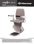
Helix Curved Stair Lift
Installation & Service Manual
www.harmar.com | 800-833-0478
WARNING! Strict adherence to these installation instruction IS required to promote the safety of
those installing this product, as well as that of those ultimately using the lift for its intended purpose. Any deviation
from these instructions will void the Limited Warranty that accompanies the product. Additionally, any party installing the product who deviates from the Installation Instructions shall be taken to agree to INDEMNIFY, SAVE AND
HOLD HARMLESS the manufacturer from any and all loss, liability or damage, including attorney fees, that might arise
out of, or in connection with, such deviation.
P 800-833-0478 | F 866-234-5680 | [email protected]
Contents
PRELIMINARY CHECKS
3
Box Contents............................................3
Tools Required.........................................4
INSTALLATION PROCEDURES
4
Preparation................................................4
Wiring..........................................................8
Chassis........................................................8
FINAL CHECKS
11
Technical Specifications 12
WIRING DIAGRAM
13
This Manual provides instructions for proper installation of this Curved Stair Lift. Please
refer to the Owner’s Manual for operating instructions. Be sure to provide the Owner’s
Manual to the owner of the lift before it is put into service. Any alterations to the
equipment without written authorization by the manufacturer may void the warranty.
Our lifts are designed to install with as little assembly as possible. If you have
questions, concerns or comments, please contact Harmar’s Technical Service
Department at 1-866-378-6848 or email [email protected].
Device Name: Harmar Helix Curved Stair Lift
Indications for Use:
The intended use of the Helix Stair Lift is to assist transfers of patients or mobility
impaired persons up and down flights of stairs
NOTE: The following symbols indicate areas where you should take
special care to avoid danger to individuals or property.
WARNING
Hazardous situation. If not avoided,
could result in serious injury to
installer or user.
2
| www.harmar.com | 800-833-0478
CAUTION!
Hazardous situation. If not
avoided, could result in serious
damage to property.
Part Number: 630-00008- Rev A
Preliminary Checks
Box Contents
Before beginning installation, please check the Curved Stair Lift contents and ensure that all
components are complete and undamaged. Also check the enclosed illustration to verify specific parts
since each lift is customized to the application. Report missing parts or shipping damage to your dealer
or the shipping company.
Contents
• Legs
• Rails
• Complete Seat Assembly
• Power Supply
• Wires
• Bag of Screws
Figure 3-1
• Pipe and Support Caps
Figure 3-2
Part Number: 630-00008- Rev A
Helix Curved Stair Lift - Installation & Service Manual 2014
3
Preparation
Tools Required
•
•
•
•
•
•
•
Ratcheting Allen Wrench (metric)
Snap ring pliers
Drill and Drill Bits
Emery/Sandpaper
Lightweight Grease
Towels for cleaning
Tape Measure (inches and
centimeters)
• Angle Meter
• Mirror for checking charger
•
•
•
•
Wire Stripper/Crimper
•
•
•
•
Shims
Fish Tape
Drill Extension Bit
Mounting Screws could be needed,
based on flooring
Picks
Optional pull strap / Ratcheting Strap
Recommended volt OHM meter
Lifts shall be installed so that means of egress is maintained as required by the
authority having jurisdiction.
The structure which equipment is installed shall be capable of supporting the
loads imposed.
The installation of electrical equipment and wiring shall conform to the requirements of NFPA70
Foot Rest Clearance. At no point in its travel shall the edge of the footrest facing
the upper landing be more than 24 inches (600 mm) above the step or landing as
measured vertically.
4
| www.harmar.com | 800-833-0478
Part Number: 630-00008- Rev A
Installation
Harmar’s Curved Stair Lift is easy to install. The standard installation
will normally take only two installers approximately two hours. The
time will vary depending on the complexity of the lift ordered and
custom designs.
IMPORTANT
Do NOT lay chair on its back.
1. Review Installation Drawing The dimensions on the drawing
show numbers on the stairs. These numbers indicate the
position of the Supports.
2. Carry chair/chassis to the location of the installation.
Usually top of stairs. It's best to be a flat section of rail.
WIRING NOTE: You may complete the wiring while putting the rail
together or use a fish tape on the completed unit to run the wire.
3. Position Stair Supports
Place on the stair based on the installation drawing but
do not bolt anything down at this point. [Figure 5-1]
4. Clean or tap screw threads that hold track together.
Check rail inside burs powder coating.
5. Assemble the Rail
Place the rail in the correct position beginning with the
first section downstairs. Unwrap the rail, checking the
label on the foam packaging for order of placement on
stairs. [Figure 5-3 & 5-4]
Figure 5-1
Figure 5-2
Figure 5-3
Figure 5-4
Follow the drawing included with the rail system.
Run a wire through the lower rail. There is a hole at the
charger location for it to come out. [Figure 5-2]
6. Check both ends of the rail and wipe clean. You may
need to clean the ends with Emery paper and add a
small amount of grease to help slide the pipes together.
[Figure 5-5]
Part Number: 630-00008- Rev A
Figure 5-5
Helix Curved Stair Lift - Installation & Service Manual 2014
5
Installation
7. Slide the pipes together one at a time starting
at the bottom in the order indicated on the
label, in order. Install on the Stair Supports.
[Figure 6-1 – 6-3]
A ratcheting strap can be used to help pull the
rails together.
Figure 6-1
8. Connect parts at the joint with the supplied
screws. Carefully tighten as you assemble the
rail [Figure 6-4 & 6-5]
Figure 6-2
Figure 6-4
Figure 6-5
Figure 6-3
When you arrive upstairs, adjust the position of the Rail and
Supports while you compare with the drawing. [Figure 6-6]
Figure 6-6
6
| www.harmar.com | 800-833-0478
Part Number: 630-00008- Rev A
Installation
9. Rail Leveling/Alignment: Using the angle meter, set the
rail to the correct angles and check the drawing to verify
that all clearances are correct.
10. Supports
Recheck angles then, using the appropriate hardware,
attach the Supports to the stairs, starting at a corner. Firmly
set the supports to the rail with set screw. Repeat the
process at the other corners; recheck angles. Complete all
other legs. [Figure 7-1 & 7-2]
Figure 7-1
Figure 7-2
NOTE: When installing to stair, ensure the hardware is long
enough. If the carpet is very thick, it might require longer
hardware (not supplied).
NOTE: Watch for tack strips. Avoid mounting on them. If you
can't avoid them, shims will be required.
Part Number: 630-00008- Rev A
Helix Curved Stair Lift - Installation & Service Manual 2014
7
Wiring & Chassis
Never lay unit on its back.
WARNING!
11.Drive Unit/Seat
Open front of chassis, by removing 4 allen screws on shroud. Set chassis upright on base. Route
wire of seat thru seat mounting hole. Install seat [Figures 8-1 & 8-2]. Install at 45° from base so the
seat stop does not hit the limit switch. Install snap ring to hold seat.
Seat Cutoff Switch (Lock)
Figure 8-1
Figure 8-2
Figure 8-3
Figure 8-4
Figure 8-5
12.Install seat lock on with snap ring [Figures 8-3 – 8-5]
Install wires for joystick on wiring
block grey wire from seat bottom
[Figures 8-6]
Black 1 on wiring block 4th from end
Green on wiring block 3rd from end
Black 2 on wiring block 2nd from end
Figure 8-6
8
| www.harmar.com | 800-833-0478
Part Number: 630-00008- Rev A
Wiring & Chassis
13. Install batteries.
14.Connect battery wire. [Figure 9-1]
15. Replace Shroud
Use caution when
handling battery.
Figure 9-1
CAUTION
16.Install chassis.
Bottom roller position. Ensure
charging point is on
the bottom. [Figure 9-2]
Ensure charging fingers
are set as low as possible
CAUTION to ensure there is no interference with rail support.
Figure 9-2
Slide on until drive hits the gear rack. Activate the joystick to drive onto rack, watching
the wheels to ensure they go on smoothly.
17.Charging Station
• Route red and black wires through hole provided in pipe by charging station
Determine which end has the AC power for the charger. Connect the charger to the red
and black wires with the connectors provided. [Figures 9-3 & 9-4]
Clip off the green wire. (Not used)
NOTE FOR OUTSIDE INSTALLS : The battery charger
needs to be placed out of the weather.
Battery
Charger
White +
Red +
Black -
Black
+
+
-
Figure 9-3
Figure 9-4
Part Number: 630-00008- Rev A
Helix Curved Stair Lift - Installation & Service Manual 2014
9
Installation
Figure 10-1
+
−
Figure 10-2
Figure 10-3
Mid station landing
The unit will stop on this when driven with the wireless
remote. It will stop for 5 to 6 seconds then continue. It
will not stop with the joystick.
Charging Station Alignment
When assembly is complete, align both Charging
Stations. Pay attention to the Charging Contacts where
the Drive Unit meets the Station. They should be
applying pressure to the charging pins.
[Figure 10-4, Figure 10-5 & Figure 10-6]
Figure 10-4
Adjustment is on the chassis
Drive the unit to the other Charging Station and check
the alignment. Adjust as needed.
Figure 10-5
18.Final Limit
• Install final limit bracket [Figure 10-7]
• Install hard final limit on gear rack [Figure 10-8]
• Pipe end caps and support caps need to be installed
Final limit hard stop [Figure 10-8 & Figure 10-9]
Figure 10-7
10
Figure 10-6
Figure 10-8
| www.harmar.com | 800-833-0478
Part Number: 630-00008- Rev A
Figure 10-9
Final Checks
Wireless Remote Reprogramming
The wireless controllers are shipped preprogrammed for
the seat.
Button
On the wireless press the little button on the board then
hold the up button on the remote for 3 to 4 seconds and
it should learn the remote.
Final Checks
Before putting the lift into operation for the user verify the following:
Figure 11-1
• Check all stops (Top, middle & bottom)
• Foot rest (Both direction of travel)
• Rail (All hardware & mounting hardware are tight)
• Final limit (Both ends of travel)
• Seat swivel (Lift won't run of seat is swiveled)
• Check all clearances to ensure there are no pinch points
• Provide the Owner’s Manual and review the lift’s operation and stops with the customer.
• Charge for 12 hours after testing is complete.
• Test wireless remote (In both direction of travel)
The lift is now ready to use. Remember to leave the Owner’s Manual with the end-user and
answer any questions they may have on the use of the Curved Stair Lift.
Part Number: 630-00008- Rev A
Helix Curved Stair Lift - Installation & Service Manual 2014
11
Technical Specifications
Technical Specifications
Weight capacity: . . . . . . . . . . . . . . . . . . . . . . . . . . . . . . . . . . . . . . . . . . . . . . . . . . . 350 lbs.
Track (rail) Type:. . . . . . . . . . . . . . . . . . . . . . . . . . . . . . . . . . . . . . Steel, Powder Coated
Travel:. . . . . . . . . . . . . . . . . . . . . . . . . . . . . . . . . . . . . . . . 20’ Standard; 164’ Maximum
Average Number of Return Trips per Charge
(varies with load, length):. . . . . . . . . . . . . . . . . . . . . . . . . . . . . . . . . . . . . . . . . . . . . . . . 10
Symmetrical Lift
(Ships and installs non-handed):. . . . . . . . . . . . . . . . . . . . . . . . . . . . . . . . . . . . . . . . No
Control in Armrest:
(left or right hand operation). . . . . . . . . . . . . . . . . . . . . . . . . . . . . . . . . . . . . . . . . . . Yes
Lift Mounts to Steps or Wall:. . . . . . . . . . . . . . . . . . . . . . . . . . . . . . . . . . . . . . . . . . Steps
Minimum Folded Width:. . . . . . . . . . . . . . . . . . . . . . . . . . . . . . . . . . . 14.37” (365 mm)
Minimum Footrest Height: . . . . . . . . . . . . . . . . . . . . . . . . . . . . . . . . . . 5 ½” (140 mm)
Clear Distance
Between Armrests:. . . . . . . . . . . . . . . . . . . . . . . . . . . . . 20.47”- 23.6” (520 - 600 mm)
Floor to Seat Height: . . . . . . . . . . . . . . . . . . . . . . . . . . . . . . . . . . . . . . . . . 24” (610 mm)
Minimum Wall to Stair Side of Rail:. . . . . . . . . . . . . . . . . . . . . . . . . . . . 4.7” (120 mm)
Seat Depth:. . . . . . . . . . . . . . . . . . . . . . . . . . . . . . . . . . . . . . . . . . . . . . . 14.96” (380 mm)
Backrest Height From Top of Seat: . . . . . . . . . . . . . . . . . . . . . . . . . 20.47” (520 mm)
Electrical Requirements:. . . . . . . . . . . . . . . . . . . . . . 120VAC 15A 240 VAC optional
Operation Power:. . . . . . . . . . . . . . . . . . . . . . . . . . . . . . . . . . . . . . . . . . 24V DC Battery
Speed:. . . . . . . . . . . . . . . . . . . . . . . . . . . . . . . . . . . . . . . . . . . . . . . . . . . . . . . . . . . . . 20 fpm
Incline Range: (max. by code):. . . . . . . . . . . . . . . . . . . . . . . . . . . . . . . . . . . . . . . . . . 45˚
Drive System:. . . . . . . . . . . . . . . . . . . . . . . . . . . . . . . . . . . . . . . . . . . Rack & Pinion Gear
Safety Features:. . . . . . . . . . . . . . . . . . . . . . . . . . . . . . . . . . . Direction Limit Switches
Final Limit Switch
Footrest Obstruction Switch
Seat Swivel/Cut-off Switch
Constant Pressure Controls
Seat Belt
Safety Edges Overspeed Governor
Emergency Stop
Safety Design Standards:. . . . . . . . . . . . . . . . . . . . . . . Complies with ASME A18.1,
CAN/CSA B44.1, ASME A17.5
Warranty:. . . . . . . . . . . . . . . . . . . . . . . . . . . . . . . . . . . . . . . . . . . 2-Year on Components
12
| www.harmar.com | 800-833-0478
Part Number: 630-00008- Rev A
Wiring Diagram
E stop
Helix Wiring Diagram
Overspeed
Upper Rollers
Seat
Chassis
Foot Rest
Lower Rollers
Final Limit
on Lower Roller
on / off
Joystick
on seat
Brake
Motor
Relay
L1
L2
L3
up
Gnd
charger
board
down
safety
common
Remote
L4
DU - +
Circuit Board
Bat +
Bat -
L1 - Control
L2 - Direction
L3 - Direction
L4 - Power
Motor Controler
20 A
Toggle Switch on Back
Fuse
On Charging
Light Light
© 2014 Harmar MKT-Harmar Helix Wiring Diagram-30Jan14 Part Number: MKT-000000 Rev A
13
Helix Curved Stair Lift - Installation & Service Manual 2014
Part Number: 630-00008- Rev A
Battery
Battery
+
-
+
-
Notes
14
| www.harmar.com | 800-833-0478
Part Number: 630-00008- Rev A
Notes
Part Number: 630-00008- Rev A
Helix Curved Stair Lift - Installation & Service Manual 2014
15
Wiring Diagram
Helix Curved Stair Lift
Installation & Service Manual
16
www.harmar.com | 800-833-0478
2075 47th Street Sarasota, Florida 34234
| www.harmar.com | 800-833-0478
Part Number: 630-00008- Rev A
© 2014 Harmar MKT-IM-Helix CurvedStairLift-16Apr14 Part Number: 630-00008- Rev A