1
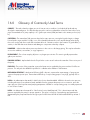
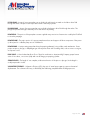
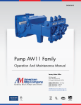
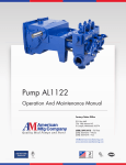
Pump AL0918BCD
Operation And Maintenance Manual
Factory/Sales Office
P.O. Box 640
736 19th Avenue NE
St. Joseph, Minnesota 56374
(888) 299-3412 ~ Toll Free
(320) 363-7273 ~ Phone
(320) 363-7274 ~ Fax
[email protected]
www.american-manufacturing.com
7k-0266
Operation And Maintenance Manual
For AL0918BCD Pump
Summary:
This is a manual for American Mfg Company AL0918BCD triplex piston pump with ball valves.
Alternate model versions:
The standard model comes with left hand pinion shaft and square keyway shaft end.
Model AL0918BCD-R comes with right hand pinion shaft and square keyway shaft end.
Page 2 of 47
Factory/Sales Office
P.O. Box 640
736 19th Avenue NE
St. Joseph, Minnesota 56374
7k-0266
(888) 299-3412 ~ Toll Free
(320) 363-7274 ~ Fax
(320) 363-7273 ~ Phone
[email protected]
www.american-manufacturing.com
AL09 Piston Pump Data
Specifications
11.6 BHP Continuous Duty (13.8 BHP Intermittent Duty)
Pump Model
AL0918
Configuration
Horizontal Triplex Piston
Number of Pistons
3
Stroke Length
2.25 Inches (57.2 mm)
Frame Load Rating
2800 lbs. (1,270 kg)
Pump Weight
200 lbs. (90.7 kg)
Direction of Rotation
Top of Shaft away from head
Internal Gear Rotation
3.6:1
Intermittent Duty Speed Rating
890 RPM (Jackshaft)
Continuous Duty Speed Rating
750 RPM (Jackshaft)
Ball Valve Max Speed Rating
625 RPM
Minimum Speed
360 RPM
Mechanical Efficiency
85%
Lubrication System
Splash, Gravity Return
Lube Oil Capacity
2.25 Quarts
Lube Oil Type
SAE 30
Maximum Fluid Temperature
140 °F (250 °F Capability)
Minimum Fluid Temperature
0 °F (-20 °F Capability)
Standard Suction Size
1.50 Inch NPT (38.1 mm)
Standard Discharge Size
1.00 Inch NPT (25.4 mm)
Fluid End Material
Cast Iron
Valve Type
Disc Valve / Ball Valve
Hydraulic Motor Mount
SAE C - 4 Bolt with 1.25”-14T
Performance Rating
Pump
Model
AL0918
Pump Capacity @ Input Speed (RPM)
Diameter
Displacement/
REV
Maximum
Pressure
Inch
mm
Gallon
Liter
PSI
kg/cm
gpm
lpm
gpm
lpm
gpm
lpm
gpm
lpm
gpm
lpm
2.25
57.2
0.0323
0.122
700
49.2
11.3
43
20.2
76
22.6
86
24.2
92
28.7
109
350 RPM
2
625 RPM
700 RPM
750 RPM
890 RPM
Specifications subject to change without notice.
Horsepower is based on 85 or 90% efficiency. Actual application horsepower
requirements can be calculated using this equation: BHP = (GPM*PSI)/(1714*0.85
or 0.90) Pump capacities listed are based on 100% volumetric efficiency.
This document contains American Mfg Company proprietary and confidential
information. It is loaned for limited purposes only and remains the property of
American Mfg Company. It may not be reproduced in whole or part or disclosed
to third parties without the prior written consent of American Mfg Company. The
document is to be returned to American Mfg Company upon request and in all
events upon completion of the use for which it was used.
Page 3 of 47
Table Of Contents
1.0
Important Safety Instructions................................................................................
6
2.0
AL0918BCD Pump Features.....................................................................................
7
3.0
Storage Instructions...........................................................................................
8
3.1
Short Term Storage...........................................................................................
8
3.2
Short Term Storage for Severe Environments...........................................................
8
3.3
Long Term Storage............................................................................................
8
3.4
Returning a Stored Pump to Operation..................................................................
9
3.5
Precautions during Freezing Weather....................................................................
9
4.0
Installation Guidelines........................................................................................
10
4.1
General Location..............................................................................................
10
4.2
Mounting Pump to Foundation and Power Source...................................................
10
4.3
Suction Piping Recommendations.........................................................................
10
4.4
Discharge Piping Recommendations.....................................................................
11
5.0
How to Start a Pump.........................................................................................
13
6.0
Lubrication of Power End....................................................................................
14
6.1
Recommended Lubricants...................................................................................
14
6.2
Oil Changes...................................................................................................
14
7.0
Inspection and Preventative Maintenance Chart......................................................
16
8.0
Component Parts List.........................................................................................
17
9.0
Service Procedures...........................................................................................
21
9.1
Removing the Fluid Cylinder................................................................................
24
9.2
Replacing Valves..............................................................................................
26
10.0
Servicing the Power End....................................................................................
29
10.1
Replacing Piston Rod Oil Seals............................................................................
29
10.2
Replacing Power End Bearings & Crankshaft.........................................................
30
11.0
Fastener Torque Requirements..............................................................................
35
12.0
Critical Clearances...........................................................................................
36
13.0
Trouble-Shooting Pumps.....................................................................................
37
14.0
Ordering Parts.................................................................................................
41
15.0
Additional Pump Assembly Products.....................................................................
42
16.0
Glossary of Commonly Used Terms......................................................................
44
17.0
Reference Information........................................................................................
46
18.0
Maintenance Log.............................................................................................
47
Page 4 of 47
List of Figures and Charts
Table 1
Pipe Pressure Chart...........................................................................................
11
Table 2
Lubricant Recommendations................................................................................
15
Table 3
Maintenance Chart...........................................................................................
16
Table 4
Component Item Numbers..................................................................................
20
Table 5
Service Tool Item Numbers.................................................................................
21
Table 6
Torque Values for Critical Pump Fasteners...............................................................
35
Table 7
Clearance Chart..............................................................................................
36
Table 8
Replacement Rubber Item Numbers......................................................................
42
Figure 1
AL0918BCD Pump Assembly with Pinion Shaft.............................................................
Figure 2A
Power End Components.....................................................................................
17
Figure 2B
Power End Components.....................................................................................
18
Figure 3
Fluid End Components.......................................................................................
19
Figure 4
Using the Knock Out Tool...................................................................................
27
Figure 5
Additional Pump Assembly Products.....................................................................
42
Figure 6
Pump Mount Bolt Pattern....................................................................................
43
7
Page 5 of 47
1.0
Important Safety Instructions
WARNING: Many accidents occur every year through careless use of mechanical equipment. You can avoid
hazards associated with high pressure equipment by always following the safety precautions listed below.
SHUT DOWN OR DISENGAGE the pump and all accessory equipment before attempting any type of service.
Failure to do this could cause electrical shock or injury from moving pump parts or components under high
pressure. Always adhere to “Lock Out” and “Tag Out” procedures. For mobile equipment, be sure engines and
hydraulics cannot be accidentally started.
BLEED OFF ALL PRESSURE to the pump and piping before performing any maintenance on the pump. Failure to
do so may spray water or chemicals at high pressure or high temperature onto service personnel.
NEVER OPERATE THE PUMP WITHOUT A PRESSURE RELIEF VALVE, rupture disc, or other type of properly sized
over pressure safety device installed.
ALWAYS USE A PRESSURE GAUGE when operating the pump. The pressure must never exceed the maximum
pressure rating of the pump or damage may occur. This damage can cause leakage or structural damage
resulting in injury to personnel.
ENSURE THAT NO VALVES ARE PLACED BETWEEN THE PUMP AND PRESSURE RELIEF VALVE. If the pump is
started with a closed or restricted valve in line before the pressure relief valve, the pump may exceed the rated
or designed pressure limits and rupture causing injury to personnel.
USE SHIELDS OR COVERS AROUND PUMPS when pumping hot water, chemicals, or other hazardous liquids.
This precaution can prevent the exposure of service personnel to these fluids should leakage occur.
ALWAYS USE GUARDS on all belt drives, couplings, and shafts. Guards can prevent personnel from becoming
entangled and injured by rotating and reciprocating parts.
USE EXTREME CAUTION WITH SOLVENTS used to clean or degrease equipment. Most solvents are highly
flammable and toxic. Observe all safety instructions on packaging.
FOLLOW NORMAL ENVIRONMENTAL GUIDELINES WHEN fluids, lubricants, or solvents are disposed of or
spilled.
NEVER MODIFY THE PUMP to perform beyond its rated specifications without proper authorization in writing
from AMERICAN MFG COMPANY.
Page 6 of 47
2.0
AL0918BCD Pump Features
The AL0918BCD pump includes the integral gear reduction pinion shaft and ball valves. Drive shaft standard end
comes with 1-1/8” diameter shaft and 1/4” square keyway.
Preferred Input Shaft Rotation
Figure 1: AL0918BCD Pump Assembly with Pinion Shaft
Page 7 of 47
3.0
Storage Instructions
Proper storage of your American Mfg Company pump will ensure that it is ready for service when needed. Follow
the guidelines below that fit the requirements of your application.
American Mfg Company pumps come from the factory without crankcase oil and are prepared for storage
periods of up to six (6) months in proper environmental conditions. Indoor storage in a dry, temperaturecontrolled location is always recommended. If pumps are to be stored short term (less than six (6) months) in a
severe environment, they should be prepared using the procedures outlined in the “Short Term Storage for Severe
Environments” section 3.2 below. If the pump is to be stored, or is inactive, for periods in excess of six (6) months, it
is necessary to prepare the pump as outlined in the “Long Term Storage” Section 3.3. Remember that any fluid that
poses an environmental hazard or is toxic must be handled and disposed of properly.
3.1
Short Term Storage
If the pump is stored in an indoor, temperature controlled environment for less than six (6) months, no special
steps are required to prepare it for storage. As a general rule for pumps in corrosive fluid applications, the fluid
end should be drained, flushed with water or other non-corrosive cleanser and compressed air used to blow dry
whenever idle.
3.2
Short Term Storage for Severe Environments
If the pump has been in service, drain any fluid from pump fluid end, flush the fluid end with water to clean out any
of the remaining pumpage and blow dry with compressed air. Pour 1/4 to 1/2 cup of internal rust inhibitor oil
described in Table 2 (see Recommended Lubricant Chart, Section 6.0 ), into the suction and discharge ports of fluid
end, and then install pipe plugs in openings. Drain the power end (crankcase) oil and remove the oil fill cap (or
plug). Pour ½ to 1 cup of internal rust inhibitor oil described in Table 2, into the oil fill hole and then install the filler
cap. Coat all exposed, unpainted metal surfaces (for example, Driveshaft) with preservative oil. Replace the oil fill
cap, and then cover the entire pump with a weather resistant covering such as a canvas or plastic tarp.
3.3
Long Term Storage
Long-term storage is defined as any period when the pump is in storage or idle in excess of six (6) months. If the
pump has been in service, drain any fluid from the pump fluid end, flush the fluid end with water to clean out any
of the remaining pumpage, and blow dry using compressed air. Pour 1/4 to 1/2 cup of internal rust inhibitor oil
described in Table 2, into the suction and discharge ports of fluid end, and then install pipe plugs in openings.
Remove the piston cup seals as described in Section 9.0 Service Procedures“Replacing Cup Type Pistons” of
this manual, seal them in a bag to protect against ozone, and store them in a separate location with a controlled
environment where they are protected from UV exposure. Drain the oil from the pump power end. Remove the rear
Page 8 of 47
cover to expose the drive components. Spray all internal parts with a rust preservative that is soluble in lubricating
oil while rotating the driveshaft several turns by hand to ensure complete coverage. Replace the rear cover and
add ½ to 1 cup of internal rust inhibitor described in Table 2. Spray a rust preventative onto all exterior machined
surfaces paying attention to any unpainted areas like the crankshaft extension. Remove the oil fill cap and store with
the piston cup seals. Cap the breather opening with a plug or other suitable means in order to keep the preservative
atmosphere sealed inside the power end. Never store the pump on the floor or ground. Always place it on a shelf
or pallet that is several inches above ground level. Cover the entire pump with a canvas or plastic tarp. Every two
months inspect the unit. Rotate the crankshaft by hand at least 4 turns during each inspection. Drain and replace the
rust inhibitor after every six (6) months of storage.
3.4
Returning a Stored Pump to Operation
Before operating a pump that has been prepared for storage, drain the preservative and lubricating oil mixture
from the power end (crankcase). If the pump has a pinion bearing, remove the rear cover and apply recommended
crankcase lubricant (Refer to Table 2 in Section 6.0) to the pinion bearings. Reinstall the rear cover, drain plug,
breather/filler cap, piston cup seals, and any other components that were removed for storage. Once these steps
have been completed, follow the normal pump start up procedures outlined in this manual.
NOTE: American Mfg Company can factory prepare units for long term storage for a nominal fee if specified at the
time of order.
3.5
Precautions during Freezing Weather
Freezing weather can cause problems for equipment when pumping water-based fluids that expand in volume
when changing from a liquid to a frozen solid state. When water is left in a pump fluid end and exposed to
freezing temperatures, the expansion of the water as it freezes can rupture the fluid cylinder of the pump and
cause equipment damage. Injury may result when starting equipment that has been damaged. Whenever the
pump is stored or idle in conditions that are near or below freezing, any water based fluids should be removed
from the pump. The best way to do this is to run the pump for a few seconds with the suction and discharge lines
disconnected or open to atmosphere. This will clear the majority of the fluid from the pumping chamber as well as
the suction and discharge manifolds. After the run, blow compressed air through the fluid end to remove all traces
of fluid. Remove the bottom plugs and cylinder covers from the fluid cylinder. Drain the liquid from the discharge
valves first and then the suction valves by lifting the valves. This ensures all fluid to be drained from the pumping
chamber between the suction and discharge valves. As an alternative to the previous procedure, a compatible
antifreeze solution can be circulated through the fluid end. RV antifreeze, propylene glycol, is recommended for this
purpose. Remember that any fluid that poses an environmental hazard or is toxic must be handled and disposed of
properly.
Page 9 of 47
4.0
Installation Guidelines
A proper installation is essential to optimal performance, long service life, and reduced maintenance requirements.
Take time to thoroughly plan all aspects of your installation.
4.1
General Location
It is important to position the pump on as flat and level a surface as possible to assist the splash oil lubrication
system. Park mobile equipment, such as sewer cleaner trucks or drilling machines, on as level a surface as possible.
Whenever possible the pump should be mounted in a clean, dry location with sufficient lighting and adequate
space for easy inspection and maintenance. Locate the pump as close to the suction source as possible to allow for
the shortest and most direct routing of the inlet piping.
4.2
Mounting Pump to Foundation and Power Source
The AL0918 pump described in this document must be mounted in a horizontal position only. Secure the pump to
the mounting surface using the four (4) holes provided in the pump base. Check motor or engine rotation direction
to ensure that the top of the pump pinion shaft rotates away from the pump fluid end when in operation. For units
that are V-belt driven, check the alignment of the sheaves after the unit is installed on its permanent mounting.
Tighten belts to the proper tension as recommended by the belt manufacturer. Verify that the sheaves are in line and
parallel to each other with a straight edge.
CAUTION: Never operate the pump without the belt guard securely installed. For direct-coupled units, ensure that
the shafts are centered and parallel when the driver is mounted to the pump. Follow the coupling manufacturer
instructions for installation procedures and tolerances.
CAUTION: Never operate the pump without a shaft guard securely installed.
4.3
Suction Piping Recommendations
Poor suction piping practices are a very common source of pump problems. To ensure proper operation it is very
important to follow good design practice in the installation of the suction system before the pump is operated.
A small amount of additional planning and investment in the piping system usually provides for better pump
performance and longer periods between service requirements. It is difficult to diagnose many pump problems
without the aid of a suction pressure gauge. For this reason, American Mfg Company recommends that a gauge
always be installed in the suction line directly before it enters the pump.
The suction line from the fluid source to the pump should be as short and direct as possible. Use rigid piping,
non-collapsible hose or a combination of both as circumstances require in your installation. The suction pipe size
Page 10 of 47
should be at least equal to or one size larger than the pump inlet. Long piping runs, low suction heads, or indirect
pipe routing may require even greater over sizing of the suction line for proper operation of the pump. A suction
and discharge pulsation dampener is recommended to reduce the effects of acceleration head to help when suction
conditions are not optimal. In some cases it may be necessary to install a booster pump in the suction line of the
pump to obtain sufficient pressure for the pump to operate successfully.
The suction line must be configured so there are no high spots in the line where air pockets can collect. These
pockets may make the pump difficult to prime and cause rough, erratic operation. A drain valve or plug should be
installed at the low point of the suction line to allow for draining before freezing conditions or for maintenance.
American Mfg Company recommends that all piping be supported independently of the pump. By supporting the
piping this way, vibrations are reduced and stress on the pump is kept to a minimum. The use of elbows, nipples,
unions, or other fittings should be minimized. Make sure that all joints and connections are airtight. Air leaks
reduce the capacity of the pump and can result in cavitation, rough operation, and/or loss of prime. To help isolate
mechanical and hydraulic vibrations, American Mfg Company recommends the use of flexible pipe couplings or
hose connections between the pump and any rigid piping.
Always ensure that calculated system Net Positive Suction Head available, NPSHa, exceeds pump Net Positive
Suction Head Required, NPSHr, by at least 5 feet (1.5 meters) of water for proper operation of the pump. NPSH
requirements for each pump model are provided on the product data sheets available through American Mfg
Company or your authorized American Mfg Company reseller. American Mfg Company does not recommend using
the pump in static lift conditions without prior factory approval.
4.4
Discharge Piping Recommendations
1. Route the discharge piping in as short
and direct a route as possible. Use the
same pipe size as the outlet of the pump.
In installations where the discharge
piping is in excess of 50 feet (15 meters)
it is suggested to use the next larger
size pipe to minimize friction losses
downstream of the pump.
CAUTION: Always use pipe or hose
that is designed for your particular
pressure requirements. Inadequate
pressure ratings can allow hose or pipe
to fail, resulting in equipment damage
and possibly personal injury. Normal
hose pressure ratings are clearly
marked on the outer surface of the hose.
Working pressure ratings for steel pipe
can be obtained from the manufacturer
or from the chart shown in Table 1.
Allowable Working Pressure For Steel Pipe (PSI @ 100F)
Pipe Size
(inches)
Pipe Schedule Number
40
80
160
XX
1/2
2,300
4,100
120
7,300
12,300
3/4
2,000
3,500
8,500
10,000
1
2,100
3,500
5,700
9,500
1 1/4
1,800
3,000
4,400
7,900
1 1/2
1,700
2,800
4,500
7,200
2
1,500
2,500
4,600
6,300
2 1/2
1,900
2,800
4,200
6,900
3
1,600
2,600
4,100
6,100
4
1,400
2,300
3,350
4,000
5,300
5
1,300
2,090
2,950
3,850
4,780
6
1,210
2,070
2,850
3,760
4,660
8
1,100
1,870
2,840
3,700
3,560
14.5PSI = 1 BAR
Table1: Pipe Pressure Chart
Page 11 of 47
2. Always use a pressure gauge in the pump discharge line. A properly functioning gauge mounted
at the pump (and before any valves) is required to accurately determine the operating pressure of a pump and
to conduct troubleshooting.
3. Ensure that all piping is supported independently of the pump to reduce vibrations and strain on the pump.
Pulsation dampeners on the discharge are recommended to reduce pressure pulsation and resulting vibration.
The use of elbows, nipples, unions, or other fittings should be kept to an absolute minimum. Avoid short radius
90° elbows; use two long radius 45° elbows instead. To help isolate mechanical and hydraulic vibrations,
American Mfg Company recommends the use of flexible pipe couplings or hose connections between the pump
and any rigid piping or the use of pulsation dampeners.
4. A properly adjusted pressure relief valve or rupture disc must be installed directly downstream of the pump to
prevent damage or injuries resulting from over pressure or deadhead conditions. The relief valve discharge line
must be as large as the pipe outlet of the relief valve. Never install valves in the relief valve discharge line or
between the pump and relief valve. American Mfg Company recommends that the discharge be returned to the
tank or drain, not back into the pump suction line.
5. It is recommended that a start-up bypass line and valve be installed to allow flow to bypass the relief valve.
This allows the pump to start in an unloaded condition (no discharge pressure).
Page 12 of 47
5.0
How to Start a Pump
CAUTION: Always take special precautions when starting a pump for the first time or after any extended
shutdown. Never assume that someone else has properly prepared the pump and system for
operation. Always check each component of the system prior to every start-up. The checklist that follows is
intended to be a general guide for starting a pump in a typical installation. Every installation is different, and
each will have different requirements to ensure safe and successful operation. It is the responsibility of the
operator to determine the correct start-up procedure for each installation.
1. Ensure that the drain plug(s) on the bottom of the pump crankcase have been installed and are tight. Ensure
that the oil level sight glass, if equipped, has been properly installed.
2. Check the oil level to ensure that the pump is properly filled with non-detergent motor oil, gear lube,
or a synthetic oil as described in Table 2 and that the oil has not been contaminated with water or other
contaminants.
NOTE: American Mfg Company pumps are shipped with no oil in the power frame and must be filled to the
proper level with the proper grade of oil prior to start-up.
3. If accessible, check the piston rods to ensure that they are free from abrasive particles or debris.
4. Ensure that the pressure relief valve and all accessory equipment have been installed and properly adjusted.
Verify that all joints are pressure tight.
5. Open the suction line valve to allow fluid to enter pump. Prime the fluid cylinder if necessary on the initial
start up or after the system piping has been drained. The valve covers may have to be cracked open to assist
with priming.
6. Check to ensure that power is locked out and tagged out. Turn the pump over by hand if possible to ensure
free, unobstructed operation.
7. Apply 10 to 20 drops of glycerin, or mineral oil to the pistons, cylinders and piston rods to lubricate the
packing and seals.
8. Make sure that all guards are in place and secure. Verify that all personnel are in safe positions and that
system conditions are acceptable for operation.
9. The pump is now ready to start. NOTICE: Whenever possible, use a bypass in the discharge line to allow the
pump to start in the unloaded condition (no discharge and pressure). Slowly close the bypass line to bring the
pump into full load conditions. Shut down immediately if the flow becomes unsteady, pressure fluctuates, or if
unusual sounds or vibrations are noted.
10. Take temperature readings of the power end and stuffing boxes. Do not exceed 170°F (77°C) on power
end.
Page 13 of 47
6.0
Lubrication of Power End
6.1
Recommended Lubricants
Few factors can influence the life of a pump more than the power end lubricant (oil). Careful selection of the right type
of oil for each particular application will help ensure optimal performance from an American Mfg Company pump.
NOTE: Lubricant temperatures should not exceed 170° F (77° C) for continuous duty or 180° F (82° C) for intermittent
duty applications. Crankcase temperatures that exceed these limits will cause the lubricant to prematurely “break
down”. The result will be poor lubrication and failure of power end components.
6.2
Oil Changes
Oil changes must be carried out after first 100 hours of operation, and subsequently after every 4,000 hours or at
least every 6 months. These intervals may be modified depending on actual operating conditions. This model pump
requires 2-1/4 quarts (2.1 liters) of oil.
Oil should be changed when hot to prevent build up of sludge deposits.
It is advisable to check oil level daily. If more than 10% of the total capacity has to be added, check for oil leaks.
Do not mix oils of different types, even if produced by the same manufacturer.
Never mix mineral and synthetic oils.
To avoid the risk of scalding or burns, pay attention to oil and power end temperature during an oil change.
Follow environmental guidelines when changing and disposing of lubricants.
Page 14 of 47
Recommended Lubricant Chart
Oil Lubricant
Type of
Service
Ambient
Temperature
General
Service
0 F to 100 F
(-18 C to 38 C)
SAE ISO Viscosity
Grade (cSt@40 C)
30
100
Synthetic Lubricant*
SSU
Viscosity
Manufacturer Brand
Name
SAE
Grade
ISO Viscosity
(cSt@40 C)
Manufacturer Brand
Name
550
Texaco® Meropa 100
Shell® Omala 100
Shell® Rotella T SAE 30
Exxon® XD-3 30 wt
Mobil® Trans HD-30
10W-30
90.0@40
15.0@100
Shell® Rotella T
Synthetic SAE 5W-40
5W-40
99.1@40
13.9@100
Mobil® SCH 627
Texaco® Meropa 68
Shell® Omala 220
Shell® Rotella T SAE 50
Exxon® HD-3 50 wt
Mobil® Trans HD-50
5W-40
90.0@40
15.0@100
Shell® Rotella T
Synthetic SAE 5W-40
5W-40
217@40
29.9@100
Mobil® SCH 630
5W-30
90.0@40
15.0@100
Shell® Rotella T
Synthetic SAE 5W-40
5W-40
12.0@100
BP® Vanellus E8
ULTRA 5W-30
10W-30
69.9@100
10.9@100
Mobil® SCH 626
NA
High Ambient
Temperature
Service
100 F to 130 F
(38C to 54 C)
50
220
1,165
NA
Cold Ambient
Temperature
Service
0 F to -30 F
(-18 C to -34 C)
20
68
350
Texaco® Meropa 68
Shell® Omala 68
Shell® Rotella T SAE 20
Exxon® HD-3 20 wt
Mobil® Trans HD-20
NA
Frequent
Start/Stop
Operation
40
150
775
Texaco Meropa®150
Specialty Items
Internal Rust
Inhibitor
Cortec® VCI 329
External Rust
Preventative
Texaco® Metal
Protective Oil L
Table 2: Lubricant Recommendations
*Synthetic lubricants are suggested for high or low temperature service. Cortec® is a registered trademark of Cortec Corporation, St. Paul, MN.
Page 15 of 47
7.0
Inspection and Preventative Maintenance Chart
Routine maintenance is an essential part of any successful pump installation. Properly maintained American Mfg
Company pumps are designed to offer years of trouble-free service.
Regular maintenance and inspection will keep your pump operating at peak performance. American Mfg
Company pumps have been carefully engineered to minimize maintenance requirements and simplify these tasks
when they are required. Regular inspections allow operators to become familiar with normal pump operation so
they can recognize the signals of potential problems and schedule maintenance. The maintenance chart in Table 3
shown below should be used as a guideline only. Many applications will require adjustment of the intervals shown
in this chart for severe or unusual operating conditions.
Interval
Break In Period
Daily
6 Months /
4,000 Hours
Component
Service
Remarks
Crankcase Oil
Change
Drain and refill with new oil after first 100 hours of operation. Ensure that the
magnetic drain plugs are cleaned to remove debris.
Inlet Strainer
Inspect
Clean if required. The amount of material in the strainer will determine the
interval of cleaning.
Complete Pump
Inspect
General inspection of pump and system to check for proper operation of equipment.
Piston Cup Sets
Inspect
Check the cylinder liner area of the pump for signs of leakage. Replace piston
cups if leakage becomes excessive.
Pump System
Flush
Crankcase Oil
Inspect
Ensure that the oil is at proper level and has not been contaminated by pumpage or condensation.
Crankcase Oil
Change
Drain and refill with new oil. Clean magnetic drain plugs.
Stuffing Box
Inspect
Check the stuffing box bolts with a torque wrench to ensure they are within
specification.
Connecting Rod Bolts
Inspect
Check the connecting rod bolts with a torque wrench to ensure they are within
specification. This should be done in conjunction with oil change.
Required for shutdown when pumping fluids that may harden or corrode the
pump if left inside once stopped.
Table 3: Maintenance Chart
Page 16 of 47
8.0
Component Parts List
To order service parts or see exact component configurations for your particular pump, refer to the cross-section
parts drawing. Contact your local American Mfg Company pump distributor or American Mfg Company if you do
not have this information.
30
6
25
20
17
3
26 12
34
24
23
13 14
2
27
18
27
16
Figure 2A: Power End Components
Page 17 of 47
8
22
4
28
21
33
31
1
29
7
15
5
19
10
32
9
11
Figure 2B: Power End Components
Page 18 of 47
53
52
49
46
51
43
44
50
62
56
39
55
40
47
1
61
41
45
60
46
58 59
57
54
47
38
62
48
39
42
Figure 3: Fluid End Components
Page 19 of 47
AL0918BCD Component Item Numbers
Component
Description
Item #
Part #
Qty
Item #
Component
Description
Part #
Qty
1
Power Frame
PPFMC 5260537
1
31
Plate, Inspection
PPFMC 1214260
1
2
Crankshaft
PPFMC 1279071
1
32
Pipe Plug, Power End
PPFMC 1187048
2
3
Pinion Shaft
PPFMC 1265098
1
33
Filler Cap or Vent
PPFMC A5054
1
4
Connecting Rod Assembly
PPFMC 18710
3
34
Screw
PPFMC 1106980
2
5
Rod Bearing
PPFMC P506697
3
38
Fluid Chamber
PPFMC 1255266
1
6
Wrist Pin
PPFMC A5006
3
39
Valve Seat
PPFMC 1225327
6
7
Crosshead Assembly
PPFMC 1250876
3
40
Piston Cup
PPFMC 5260052
3
8
Seal Holder
PPFMC 1283601
3
41
Piston Holder
PPFMC 8495
3
9
Oil Seal, Piston Rod
PPFMC 1283603
6
42
Hex Nut
PPFMC 8309
3
10
Seal Retainer Nut
PPFMC 1283600
3
43
Nut Retainer
PPFMC A5016
3
11
Gasket, Seal Retainer
PPFMC 1283602
3
44
Piston Retainer
PPFMC 1207289
3
12
Bearing Housing, Blind
PPFMC 1279064
2
45
O-Ring, Rod Seal
PPFMC 1101176
3
13
Shim, Bearing Housing
PPFMC 1252594
5
46
Gasket, Fluid Chamber
PPFMC 1280024
6
14
Gasket, Bearing Housing
PPFMC A5025
2
47
Plug, Pipe
PPFMC P501267
6
15
Back Cover
PPFMC 1279063
1
48
Plug, Suction
PPFMC 1105105
2
16
Gasket, Back Cover
PPFMC 1279065
1
49
Valve Cover
PPFMC A5003
3
17
Pinion Housing, Drive
PPFMC A5005
1
50
Gasket, Valve Cover
PPFMC 1280026
3
18
Pinion Housing, Blind
PPFMC 1225769
1
51
Clamp, Valve Cover
PPFMC 1271716
3
19
Petcock
PPFMC 1187039
1
52
Stud, Valve Cover
PPFMC A5012
6
20
Gasket, Pinion
PPFMC A5026
2
53
Hex Nut, Valve Cover
PPFMC 1121511
6
21
Nameplate
PPFMC 5262738
1
54
Cylinder Cover
PPFMC A5002
3
22
Lube Fitting
PPFMC 1100759
3
55
Gasket, Cylinder Cover
PPFMC 1280025
3
23
Bearing Cone, Crank
PPFMC 1101242
2
56
Cylinder
PPFMC 1272060
3
24
Bearing Cup, Crank
PPFMC 1177287
2
57
Clamp, Cylinder
PPFMC 1271415
3
25
Bearing, Pinion
PPFMC 1104444
2
58
Stud, Cylinder Cover
PPFMC A5011
6
26
Key
PPFMC 1187577
1
59
Stud
PPFMC A5009
2
27
Cap Screw, Pinion Bearing
PPFMC 1100068
12
60
Seal Holder
PPFMC 1281655
3
28
Screw
PPFMC 1187413
2
61
Hex, Nut, Cylinder
PPFMC 1121511
8
29
Cap Screw, Back Cover
PPFMC 1106910
14
62
Ball
PPFMC 1101418
6
30
Set Screw
PPFMC 1103470
3
Table 4: Component Item Numbers
Page 20 of 47
9.0
Service Procedures
American Mfg Company pumps are designed to simplify all required maintenance. The following sections illustrate
step-by-step instructions for performing the most common service procedures of a pump. Read each section before
starting service work on the pump. Refer to Figures 2 and 3 for the location of components.
WARNING: Many accidents occur every year through careless use or service of mechanical equipment. You can
avoid hazards associated with high-pressure equipment by always following the safety precautions listed in Section
1.0.
Service Tip -- Press the piston assembly into the liner until
the sealing lip has just entered the front of the liner. Use
a small amount of glycerin on the ID of the liner to help
lubricate the piston during installation. After the liner
has been installed in the pump power frame, drive the
piston assembly fully to its stop using the American Mfg
Company piston tool (PPFMC A5049) and a rubber
mallet.
1. It is recommended that a sufficient quantity of
clean water be pumped through the fluid end before
starting any service procedures that involve fluid end
components. This will remove a significant portion of
contaminants left in the fluid cylinder by the normal
pumpage and improve the ability to work with parts
or see potential problems.
NOTE: The following tools are available and may be
purchased at American Mfg Company’s worldwide
network of distributors.
Component Description
Part #
Tool, Bearing Press For Pinion
PPAM A000387000
Tool, To Tighten Packing Nut
PPAM A000396000
Tool, Ball Seat Driver
PPAM A000398000
Tool, Ball Magnet
PPAM A000239000
Tool, For Housing Cup Press
PPAM A000401000
Tool, Hand Crank Pinion
PPAM A000402000
Tool, Stud Nut
PPAM A000410000
Tool, Piston Nut Remover
PPFMC A5049
2. Bleed off all pressure inside pump fluid end before
starting any service work. Shut the valve off on the
inlet piping, if provided, to prevent flow of liquid from
the source into the pump during service.
Table 5: Service Tool Item Numbers
CAUTION: Check to ensure that the power is locked out and tagged out (motor or engine cannot be started).
3. To service the piston cup seals (40) approximately 2 feet of
clearance is required between the front of the pump cylinder cover
(54) and any obstructions. If there is insufficient clearance, the
pump must be removed and relocated to an area where adequate
clearance exists.
Page 21 of 47
4. To access the piston cup seals (40), the cylinder cover clamps
(57) must be removed . Remove six of the nuts (61) holding the
cylinder cover clamps (57) in place, and then remove the cylinder
covers (54). Do not remove the two nuts (61) on the opposite
corners of the fluid cylinder, as they keep the cylinders (56) and
fluid cylinder mounted on the pump during this operation. Remove
the (55) cylinder cover gaskets.
5. Using a socket wrench with a long extension, remove the hex
piston nut (42) from the piston/crosshead rod (7). This nut secures
the piston assembly to the piston/crosshead rod.
6. Following the hex piston nut (42) removal, use the American
Mfg Company piston tool (PPFMC A5049) to pull the piston
assembly from the cylinder (56). Insert the American Mfg
Company piston tool inside the cylinder until flush with the face of
the slotted piston retainer nut (43). Twist the tool to engage and
lock the tabs of the tool inside the mating slots in the retainer nut.
7. Pull the piston assembly free of the pump using a combination
pulling and twisting motion.
Page 22 of 47
8. Place the flats on the bottom of the piston holder (41) in a
vice or clamp securely. Using the American Mfg Company piston
tool (PPFMC A5049), unscrew the piston retainer nut (43) and
remove. The piston cup (40) and piston retainer (44) may now be
removed. Tool PPFMC A5049 is designed with hex nut for using
torque wrench to appy proper torque as indicated in 11.0.
9. Inspect all parts for damage or unusual wear. Ensure that the
interior surface of the cylinder (56) is smooth and free of cracks
or grooves. New piston cups (40) will fail prematurely if installed
in liners with damaged bores. American Mfg Company strongly
recommends that all three piston cups be replaced, not just those
that show signs of leakage, whenever this type of service is
performed. This will maximize operational time between service
intervals.
10. Reverse steps 3 through 9 to rebuild the pump after worn
or damaged components have been replaced. American Mfg
Company recommends that all seals and gaskets that are
disturbed during the service procedures be replaced. This includes
the rod seal o-ring (45) that is located on the piston/crosshead
rod (shown) directly behind the piston assembly. Some pump
models have the o-ring in a groove in the piston holder instead of
a separate seal holder. Lubricate the piston cups and piston rods
during assembly.
11. Tighten all fasteners to the values specified in Fastener Torque
Requirements, Section 11.0 of this manual.
Page 23 of 47
9.1
Removing the Fluid Cylinder
NOTE: The fluid chamber (56) may be removed to inspect for internal damage, to be repaired, to replace the fluid
cylinder, to replace damaged cylinders, cylinder o-rings, or to service piston rod seals.
Refer to Figure 3 for illustration of parts.
1. It is recommended that a sufficient quantity of clean water be pumped through the fluid end before starting
any service procedures that involve fluid end components. This action will remove a significant portion of
contaminants left in the fluid cylinder by the normal pumpage and improve the ability to work with parts or see
potential problems.
2. Bleed off all pressure inside pump fluid end before starting any service work. Shut the valve on the inlet
piping if provided to prevent flow of liquid from the source into the pump during service.
CAUTION: Check to ensure that the power is locked out and tagged out
3. Remove the cylinder cover clamps (57) and cylinder covers
(54) as described in the previous section. Remove the outside
corner fluid chamber nuts (61) if they are still in place.
4. Rock the fluid cylinder (fluid chamber) to loosen from the
cylinders (liners) (56), and pull free of the fluid end studs. If the
pistons have already been removed, take care to ensure that the
cylinders (liners) do not fall off of the front of the power end and
become damaged.
5. To remove the piston assemblies, refer to the previous section
(9.0).
6. Inspect all parts for signs of wear or damage. Replace parts if required.
Page 24 of 47
7. Always replace the cylinder gaskets (46) when the cylinders
have been moved or replaced.
8. Installation will be the reverse of this procedure.
9. Torque all fasteners as outlined in the Fastener Torque Requirements, Section 11.0 of this manual. Please note that
if the nuts (61) on the fluid cylinder studs (58 and 59) are not properly torqued, a failure is likely.
Page 25 of 47
9.2
Replacing Valves
1. Ball type valves are supplied with the AL0918BCD pump.
2. A minimum of approximately 2 feet of clearance is required above, below, and in front of the pump fluid
cylinder to allow valve service without removal of the fluid end. If sufficient clearance is not available, the fluid
end must be removed as outlined in previous section (9.1) and taken to a work shop for valve service. The
following procedure is written under the assumption that sufficient clearances exist.
3. Remove the three suction plugs (48) from the bottom of the fluid
chamber (38).
4. Remove the six valve cover nuts (53) holding the valve cover
clamps (51) and then remove the three valve covers (49) from the
fluid cylinder.
5. The cylinder covers (54) allow access for inlet valve removal.
Remove the cylinder covers as described in section 9.1, steps 1
through 9.
Page 26 of 47
6. For ball valves, the balls are not retained in the valve seat.
The ball can easily be removed from the valve assembly by
lifting it out of the open cage portion of the valve seat with
American Mfg Company tool PPAM A000239000. Then
remove the valve seat from the fluid chamber.
7. To remove the valve seat use knock out tool PPAM
A000398000. This tool is inserted from the bottom of the fluid
cylinder. The tool has a step at the end that mates with the
valve seat. The tool is then stuck sharply with a hammer and the
valve is loosened. The suction valve seats can be removed first
through the cylinder cover. The discharge valve seats can be
removed through the valve covers.
Discharge Valve
Cylinder Cover hole with
cover & clamp removed
Suction Valve in place
Fluid Cylinder Body
PPAM A000398000
Strike on this end with a hammer
to remove the valve
Figure 4: Using the Knock Out Tool
Page 27 of 47
8. Installation of Ball Valve Seats
The suction valve seats must be installed before the discharge valve seats can be installed. The following
re-assembly procedure is applicable for both.
A. Select a new valve seat and check to ensure the taper on the seat is clean.
B. Carefully clean the taper in the fluid cylinder and on the seat with a cleaning solution and a clean cloth.
Small scratches can be removed with steel wool or 100 grit emery paper. Remove all dirt, grease, oil,
water, or any other contaminants from the surfaces. Do not oil the seats or the seating surfaces in the fluid
cylinder. Confirm that they are dry before installation.
C. Position the valve seat directly over the mating taper in the fluid cylinder.
D. Let the valve seat drop into the taper. Check to see that the seat is sitting in the taper properly and not
cocked to one side. If the seat drops straight, it will seize on the taper. When correctly seated, it cannot be
pulled up by hand.
E. Use tool PPAM A000398000 to install the valve seats. Place the tool on the top surface of the valve seat.
Strike with a hammer three times to set the valve seat.
F. Repeat steps A through E for the discharge valves.
9. After the valves have been replaced, American Mfg Company recommends that the valve cover be replaced.
Install the valve cover with the new gasket (50) in place, and install the valve cover clamps (51) over the valve
cover studs (52). Replace valve cover and valve cover hex nuts (53).
10. Torque the valve cover hex nuts or hex plugs to the recommend values listed in the Fastener Torque
Requirements, Section 11.0, of this manual.
Page 28 of 47
10.0
Servicing the Power End
10.1
Replacing Piston Rod Oil Seals
NOTE: Ensure that all pressure inside the pump fluid cylinder has been bled off before starting any service work.
CAUTION: Check to ensure that the power is locked out and tagged out
The piston rod oil seals (9) retain oil in the power end and prevent contamination from entering the power end by
way of the piston rods. The fluid end and cylinders must be removed as outlined in the previous sections to provide
access to these seals.
1. Rotate the seal retainer (10) counter clockwise until it is unscrewed from the frame, then slide off the rod. Use
a larger flat head screw driver as shown or use tool PPAM A000396000.
2. Pull the seal holder (8) out of the pump frame and slide off of
the rod. It may be necessary to insert a screwdriver or pointed
tool into one of the holes in the seal holder to help extract it from
the power frame.
3. Remove the seal retainer gasket (11) from the power frame.
Inspect the seals (9) and note the orientation of the seals prior to
removal. The seals may now be removed from the seal holder and
discarded.
4. To rebuild, insert new seals (9) in the seal holder (8), taking
care to ensure they are oriented in the same manner as the ones
that were removed. Do not reuse seals that have been removed
from the pump. Replace the seal retainer gasket (11) if it shows
signs of deformation or damage.
5. Wrap tape or other material over the exposed piston rod
threads to protect the new seal lips from damage. Install the
seal retainer gasket then slide the seal holder over the protected
threads and into the pump frame. Care must be taken to ensure
the seal lips are not folded or cut when passing over the ends of
the rod.
6. Ensure that the gasket (11) and seal holder (8) are in place,
install the seal retainer (10) and tighten until it bottoms out. Do not
over tighten as it can damage the seal retainer gasket.
7. Remove the protective material that is covering the rod threads. Rebuild the remainder of the pump as
outlined in previous sections. Torque all fasteners as outlined in the Fastener Torque Requirements, Section 11.0,
of this manual.
Page 29 of 47
10.2
Replacing Power End Bearings & Crankshaft
WARNING: Disconnect the driver from the pump and ensure that suction and discharge lines are disconnected or
blocked and have no pressure applied.
1. Removal of the fluid cylinder simplifies crankshaft removal on AL0918BCD models.
2. Remove magnetic pipe plug (32) to allow all oil to drain from power frame (1).
3. Remove all rear cover cap screws (29). Remove the back cover
(15) and back cover gasket (16) from the power frame.
4. Remove the end cap of each connecting rod (4) by unscrewing
the two hex nuts that hold each cap to the connecting rod body.
The cap can be removed from the body by tapping with a rubber
mallet on the cap screws to remove them and then tapping on the
end cap to loosen it. Take care to not damage the threads on the
cap screws.
5. Slide the two rod bearing halves (5) from each connecting rod
(4). Note that these parts sometimes adhere to the pins (journals)
on the crankshaft (2).
Page 30 of 47
6. NOTE: Connecting rods and caps are matched sets and must
always be re-assembled with their original mate and in the same
orientation. Note the numbered codes stamped on each half of the
connecting rod assemblies and make certain they are installed as
matched set and in the same orientation when re-assembling the
pump.
The AL0918BCD pumps are configured with pinion shafts for internal
gear reduction.
7. For AL0918BCD pumps with the pinion shaft, remove the hex
head cap screws (27), the left and right pinion housings (17 and
18). The gaskets (20) may adhere to the power frame surface and
can be left in place if they are not damaged.
8. The pinion shaft (3) with bearings may then be removed from
the drive side by using a brass rod (or other soft material) and
mallet to drive the shaft out.
Installation Tip: Mark the bearing housings and power frame for
installation in the original position.
9. Remove the hex head cap screws (27), bearing housings (12)
gaskets (14) and shims (13) from both sides of the pump. Count
and record the shims on each side to facilitate assembly. The
gaskets (14) may adhere to the power frame surface and can be
left in place if they are not damaged. The bearing cones (23) will
remain in the bearing housing.
Page 31 of 47
10. To remove the crankshaft on AL0918BCD models work the
crankshaft to the left when viewing from the rear opening of the
power frame. The throws or journals may have to be rotated
as the crank is removed to clear the connecting rods. Slip the
crankshaft end on the right out the back of the power frame and
remove. The crankshaft should be handled carefully to prevent the
critical bearing surfaces from being scratched or damaged.
11. Bearing cups (24) may be removed from the crankshaft. Bearing cones (23) can be removed from the
bearing housing using a puller if a sufficient lip is available for the puller arms to grab. An alternate procedure
involves running a weld bead around the inside surface of the cup. When cool, this will reduce the interference
between the cup and bearing housing enough to free the cup. If either the cup or cone is replaced, the
corresponding cup or cone should be replaced as they are a matched set. Tool PPAM A000401000 can be
purchased to press bearing cones (23) into bearing housing.
12. Pull the connecting rod/crosshead assemblies (7) from the
power frame. Mark each connecting rod and crosshead assembly
to ensure they are reassembled into the same bore from which
they were removed.
13. Remove the set screw (30) and slide the wrist pin (6) out of the crosshead (7) if crosshead or connecting rod
(4) requires service. Keep components matched together.
14. Inspect all components for signs of wear or damage and replace if required. Carefully check the crankshaft
bearing surfaces for pits, scratches, or other signs of wear. The connecting rod bearings should be inspected for
deep scratches or the top metal surface worn away.
15. Thoroughly clean all parts with solvent and apply a thin coat of oil before reassembly.
16. Tapered roller bearing cups (24) must be heated to aid in assembly onto the shaft. Always observe proper
safety procedures and use heat resistant tools and gloves when handling hot parts. There are a number of
recommended methods for heating bearings. Electric ovens or electrically heated oil baths may be used, but
only when accompanied by proper thermostatic control.
Page 32 of 47
17. To replace the tapered roller bearings on the crankshaft, heat the cones to a maximum of 300° F (149° C).
Slide them down the shaft unit they are fully seated against the shoulder. The hot cup may pull away from the
shoulder unless it is held in position until it cools enough to grab the shaft. Use a .001” thick feeler gauge to
ensure the cone is fully seated against the shoulder after the parts have cooled.
18. Use a press to seat the new cones (23) into the bearing housings. Never use new bearing cups with old
bearing cones. Always use matched sets from one manufacturer.
19. Reassemble the crosshead assemblies and connecting rods. Ensure that the set screws (30) retaining the
wrist pin (6) are in place. The set screw must engage the flat on the wrist pin. Refer to Section 11.0 for torque
specifications.
20. Push the crosshead/connecting rod assemblies fully forward in power frame to provide maximum clearance
for the crankshaft. Ensure crosshead assemblies are replaced in the same orientation and in the same cylinder
bore they were originally.
NOTE: The oil cup pocket feeds lubricant to the wrist pin bushing. This is located on the top of the connecting
rod and should be in the up position.
21. Install crankshaft in the power frame. Take care not to scratch the bearing surfaces of the crankshaft.
22. Inspect the gasket (14) that seals the bearing housing and replace if damaged. Reinstall the shims (13)
and bearing housings (12). As a starting point, install the same number of shims that the pump originally had
prior to service work. When tightening the fasteners retaining the bearing cover, use a crisscross pattern for
tightening with a torque wrench.
23. Replace the rod bearings (5) in the connecting rod and connecting rod caps. Ensure that rod caps are
properly assembled with their mating connecting rod. Torque the fasteners holding the end caps to the mating
rod per the values given in Fastener Torque Requirements, Section 11.0 of this manual. Use back and forth
pattern tightening with a torque wrench. After the cap screws are torqued, a light strike to the cap with a rubber
hammer will help properly seat the rod bearings.
24. A dial indicator must be used to properly adjust the endplay of the crankshaft. Improper adjustment may
result in excessive temperature, noise, and reduced bearing life. American Mfg Company recommends between
.002” tight to .003” loose of internal axial clearance (end play) when properly assembled. The final adjustment
must be verified using a dial indicator as indicated in the following steps 29 through 32.
25. Turn the crankshaft at least two (2) revolutions to ensure the connecting rods (4) are loose and that there is
no binding in the rod bearings (5), the wrist pin (6) joints are free, and the crossheads move freely in the power
frame (1). Tool PPAM A000402000 may be purchased to help turn the crankshaft
Page 33 of 47
26. Move the crankshaft to one side of the power frame using a
light tap from a rubber mallet or a pry bar. Rotate the crankshaft
several turns and repeat the light taps from a rubber mallet or the
use of a pry bar to ensure the crankshaft is to one side.
27. Mount indicator base on the power frame with the indicator
tip on a machined shoulder surface of the crankshaft (do not
measure from a cast surface) and the axis of the indicator parallel
to the crankshaft.
28. Set the dial indicator to zero.
29. Move the crankshaft back over to the opposite side and
read the bearing end play as total indicator movement. Rotate
the crankshaft several turns, then repeat moving the crankshaft
in the direction described in this step. Repeat the dial indicator
measurement. Remove or add shims as necessary to achieve
proper endplay (.002” tight to .003” loose). Distribute shims
equally on both bearing housings. Verify the endplay with the dial
indicator per this procedure described before final assembly.
30. Install the piston rod seal holder (9) and seal retainer (8) in the power frame per instructions in section
10.1. The crankshaft should turn freely.
31. Complete reassembly of pump. Tool PPAM A000387000 can be purchased to aid in the assembly of the
pinion bearing if needed.
32. Torque all fasteners as outlined in Fastener Torque Requirements, Section 11.0 of this manual.
Page 34 of 47
11.0
Fastener Torque Requirements
NOTICE: No pump service procedure is complete without applying the proper fastener torque. Failure to properly
tighten the pump bolts could cause the pump to leak or possibly allow the pump to fail. Always use a calibrated
torque wrench during the installation of all critical fasteners listed in Table 6 below. Values are in foot- pounds (Ft-lb)
and Newton meters (N-m). Typical sizes are shown in Table 6 below. Refer to Table 7 for other sizes that may be
used depending on application.
Power End Torque Values
Item #
Component Description
Size
Ft-lb
(N-m)
4
Connecting Rod Bolts
.438 (7/16)
45
61
43
Piston Assembly Nut
.750 (3/4)
35
47
42
Piston Rod Hex Nut
.500 (1/2)
35
47
28
Bearing Housing Screws
.375 (3/8)
25
34
28
Pinion Housing Screws
.375 (3/8)
25
34
29
Back Cover Bolts
.375 (3/8)
20
27
27
Cross Head Set Screw
.313 (5/16)
10
14
61
Cylinder Attach/Clamp Nut
.500 (1/2)
75
102
53
Valve Cover Nut
.500 (1/2)
60
81
Table 6: Torque Values for Critical Pump Fasteners
Page 35 of 47
12.0
Critical Clearances
When maintenance requiring disassembly of the power end is performed, the following clearances should be
checked to see if they are within factory specification or within maximum allowable limits. Additional clearance
is allowed for component wear. This additional clearance is a maximum of .002 inches of total diametral wear
that can be added to the clearance values in Table 7. For radial clearance, use ½ of the total diametral value. All
dimensions are shown in inches.
Description
Clearance
Crankshaft Throw Diameter (Stroke)
2.25
Crankshaft Pin or Journal (OD)
2.8743/2.8748
Connecting Rod / Crank Clearance (Max. Total)
.003
Crosshead Diameter (OD)
2.749/2.750
Crosshead Cylinder Bore (ID)
2.7515/2.7535
Crosshead to Bore Clearance (Max. Total)
.0045
Wrist Pin Bushing Bore (ID)
1.0005/1.0015
Wrist Pin to Bore Clearance (Max. Total)
.002
Table 7: Clearance Chart
Metric Conversion:
1 inch = 25.4 mm
1 mm = 0.03937 inches
NOTE: Clearances shown are total diametral values: For radial clearance use ½ the value shown.
Page 36 of 47
13.0
Trouble-Shooting Pumps
This chart is designed to aid in the solution of pump and pump system problems. Once the problem has been
identified, work through the possible causes and solutions until the problem has been corrected.
Symptom
No flow from
pump
Insufficient
pressure from
pump (ONLY)
Insufficient
flow from
pump (ONLY)
Insufficient
floor or
pressure
AND rough
operation
(pump pounds
or vibrates)
Possible Cause
Possible Solution
• No liquid in reservoir (tank)
• Ensure lines are connected and fill tank
• Inlet line valve closed
• Ensure lines are connected and open valve
• Inlet strainer is totally clogged with debris
• Clean or replace strainer
• Crankshaft is not turning
• Check for power to drive and drive connections
• Pump speed is too low
• Check belt tightness or power to motor
• Relief valve improperly adjusted or worn
• Check relief valve and adjust setting
• Insufficient system resistance (worn nozzle)
• Properly service system
• Worn check valves
• Inspect check valves and repair or replace
• Excessive leakage from pump seals
• Adjust or replace packing or damaged parts
• Pump speed is too low
• Check belt tightness or power to motor
• Relief valve improperly adjusted or worn
• Check relief valve and adjust setting
• Worn pump valves
• Inspect pump valves and repair or replace
• Excessive leakage from pump seals
• Adjust or replace packing or damaged parts
• Plunger or piston worn
• Replace plunger or piston
• Valve seat washed out in fluid cylinder
• Repair or replace fluid cylinder
• All pump cylinders not primed
• Prime all chambers
• By-pass or relief is piped back to suction
• Pipe back to reservoir (tank)
• Inlet line too long or too small in diameter
• Increase suction pipe size
• Insufficient NPSHA
• Provide more NPSH
• Air leaks in suction line or fittings
• Correct installation to stop leaks
• Vortex in tank near inlet pipe opening
• Increase submergence or baffle to stop vortex
• Air entering booster pump
• Correct installation of booster pump
• Pump valve stuck open or closed
• Clean and deburr valve
• Valve assembly damaged or unseated
• Properly seat or repair valve
• Valve seat washed out in fluid cylinder
• Repair or replace fluid cylinder
• Gas pocket formation from high spots in suction
• Correct suction line installation
Page 37 of 47
Symptom
Pump runs
rough,
knocks, or vibrates (ONLY)
Possible Cause
Possible Solution
• Broken or weak valve spring
• Replace valve spring
• Valve damaged or unseated
• Repair/replace valve or re-seat
• Loose plunger, piston, or rod
• Tighten loose components
• Low oil level in power end
• Fill to proper level
• Excessive connecting rod brg clearance
• Check cap torque or replace bearings
• Excessive main bearing clearance
• Adjust end-play
• Worn wrist pin or bearing
• Replace worn components
• Pump running backward
• Correct rotation
• Loose sheaves or bushings (v-belt drive)
• Tighten loose components
• Gear tooth cracked or broken
• Replace gear
• Insufficient NPSHA
• Provide more NPSH
• Excessive acceleration head in suction line
• Install suction stabilizer
• Pulsation dampener improperly charged
• Charge to proper pressure
• Inlet line too long or too small in diameter
• Increase suction pipe size
• Worn piston seal allows air ingress (usually
observed when booster not used)
• Replace piston seal
Rapid suction pressure
fluctuation
• Pump cavitation
• Increase suction size or NPSH
• Air is entering suction line
• Correct installation to stop leaks
Piping vibration
• Same as Pump runs rough above
• See above
• Excessive pressure variation in discharge
• Install discharge pulsation dampener
• Piping inadequately supported
• Install supports at proper locations
• Excessive short-radius elbows or tees
• Correct installation to minimize turns and shortradius fittings
• Discharge pressure too high
• Reduce system back-pressure or adjust relief valve
• Plungers or pistons too large
• Install smaller plungers to reduce flow
• Speed too high
• Reduce speed
• Packing too tight
• Loosen gland (Adjustable packing)
• Misaligned coupling
• Correct alignment
• Belts too tight
• Correctly adjust belt tension
• Power end bearings too tight
• Increase end-play
• Low motor voltage
• Supply correct voltage
Pump requires excessive power
Page 38 of 47
Symptom
Power end
overheats
(over 180°
F) and/
or reduced
power component end
life
Possible Cause
Possible Solution
• Discharge and/or suction pressure too high
• Reduce pressure or reduce plunger size
• Oil level too high or too low
• Adjust to correct oil level
• Contaminated power end oil
• Refill with clean oil & eliminate contamination
• Incorrect oil viscosity or grade
• Fill with correct oil
• Misaligned coupling
• Correct alignment
• Belts too tight
• Correctly adjust belt tension
• Pump running backward
• Correct rotation
• Pump located too close to heat source
• Remove heat source or insulate power end
• Worn or damaged power end bearings
• Replace damaged bearings
Crankshaft
jerks or
starts and
stops rotation
• Drive belts loose and slipping (if equipped)
• Correctly adjust belt tension
• System relief valve pressure set too high
• Reduce relief valve pressure setting
• Discharge line blocked or partially blocked
• Clear obstructions from piping system
Fluid leaking
from pump
• Piston cups are worn
• Replace piston cup
• Piston to rod o-ring damaged
• Replace o-ring
• Fluid cylinder bolts not properly tightened
• Properly tighten and torque bolts
• Fluid cylinder o-rings (or gaskets) damaged
• Replace damaged o-rings or gaskets
• Highly abrasive particles in fluid
• Install strainer or filter
• Packing or piston cups run dry
• Correct problem & replace packing or cup
• Incorrect packing or cups for fluid type
• Change to correct packing or cup
• Inadequate packing lubrication
• Correct problem and replace packing
• Pump was run dry for extended time
• Correct problem and replace cups
• Plunger (or rod) misaligned to stuffing box
• Correct alignment
• Worn plunger or cup holder
• Replace plunger or cup holder
• Worn cylinder liner bore
• Replace cylinder liner
• Packing gland too tight (adjustable)
• Properly adjust gland nut
• Packing gland too loose (adjustable)
• Properly adjust gland nut
• Too much packing in box
• Correct installation problem
• Broken or weak spring
• Replace spring
• Highly abrasive particles in fluid
• Install strainer or filter
• Cavitation damage
• Correct problem and replace damaged valves
• Air leaking into suction line or stuffing box
• Correct problem and replace damaged valves
• Suction inlet insufficiently submerged
• Increase submergence or baffle to stop vortex
• Relief valve or bypass piped to suction
• Pipe back to reservoir (tank)
• Valve damaged by improper installation
• Replace damaged components
Reduced
packing or
piston cup
life
Reduced
valve life
Page 39 of 47
Symptom
Cracked
fluid cylinder
or broken
fluid end
bolts
Broken
crankshaft or
connecting
rod
Power end
oil is contaminated
Possible Cause
Possible Solution
• Discharge pressure too high
• Reduce system back pressure or relief valve
• Hydraulic shock (cavitation or entrained air)
• Correct piping system problem
• Discharge valve stuck closed
• Replace damaged components
• Fluid freezing in fluid cylinder
• Change procedure to drain fluid when cold
• Material or manufacturing defect
• Replace defective component
• Bolt or nut not properly torqued
• Replace fluid cylinder and properly torque
• Excessive piping loads on fluid end
• Add supports to piping
• Discharge pressure too high
• Reduce system back pressure or relief valve
• Suction pressure too high
• Reduce suction pressure or plunger diameter
• Fluid freezing in fluid end
• Change procedure to drain fluid when cold
• Hydraulic shock due to cavitation
• Correct piping system problems
• Material or manufacturing defect
• Replace defective components
• Extended operation with failed piston cup
• Replace piston cup and improve monitoring
• Hi-pressure sprayer nozzle near breather or seals
• Provide shields to protect breather and seals
• Deflector shields are missing or damaged
• Repair or replace deflector shields
• Crosshead extension seals damaged
• Replace oil seals
• Excessive capacity in liner wash system
• Reduce capacity in liner wash system
• Improperly adjusted liner wash nozzle
• Adjust liner wash nozzle
Page 40 of 47
14.0
Ordering Parts
Service parts are available through American Mfg Company ’s worldwide network of distributors or from the
original supplier. If unsure where to purchase parts, contact American Mfg Company customer service for the
location of an authorized parts retailer in your area.
Always insist on genuine American Mfg Company replacement parts.
Use the assembly drawing and bill of material included on pages 17 through 20 with this manual to determine the
components and corresponding part numbers required to service the pump. Make sure that the model number on
the drawing or bill of material matches the model number of the pump requiring parts.
When ordering parts, always reference the model number of the pump with the order. These numbers can be found
stamped on the metal name tag affixed to the power end of every pump. By referencing these numbers you can
ensure that the components you receive work as intended with your pump. Be sure to inquire about any special
service tools or complete maintenance kits.
Page 41 of 47
15.0
Additional Pump Assembly Products
PRESSURE GAUG
E
(P PA M A000380000)
PRESSURE RELIF
E
VALVE (PPFMC 3546492)
DISCHARG E
SURGE CHAMBER
FOR 1" NPT
(P PA M A000524000)
DISCHARGE LINE
1" NPT
INT AKE SURGE CHAMBER
FOR 1.1/2" NPT
(P PA M A000525000)
1.1/2" NPT
INT AKE LINE
Figure 5: Additional Pump Assembly Product Item Numbers
Replacement Rubbers
Component Description
Piston Rubber 2-1/4 (Carbox Nitrile XNBR)
Part #
PPFMC 5260052
Alternates
Component Description
Part #
Piston Rubber 2-1/4 (Neoprene)
PPFMC A3434N
Piston Rubber 2-1/4 (HSN)
PPFMC P513766
Table 8: Replacement Rubber Item Numbers
Page 42 of 47
23.219"
1" NPT DISCHARGE
BOTH SIDES
OI L FILL
PETCOCK OIL
LEVE L
11.375"
8.375"
8.062"
11.875"
5.00"
2X 7/8 C-BORE X 13/64 DEEP
12.687"
4X 1/2-13 TAP 5/8" DEEP
MOUNTING HOL E
4.281"
4.250"
12.500" 8.500"
3X 1-1/2" NPT SUCTIO N
8.563"
8.750"
2.536"
1.812"
15"
1/2-13 TAP, 3/4" DEEP
MOUNTING HOL E
0.25"
5.813"
Figure 6: Pump Mount Bolt Pattern
Page 43 of 47
16.0
Glossary of Commonly Used Terms
CAPACITY -- The total volume throughput per unit of time at suction conditions. It includes both liquid and any
dissolved or entrained gases. For all practical purposes this can be considered the volume flow rate in the suction
pipe. The standard unit of pump capacity is U.S. gallons per minute (GPM) and metric cubic meters per hour (m3/
hr).
CAVITATION -- The state where fluid pressure drops below vapor pressure, causing the liquid to begin to change
from a liquid to a gas and boil. Usually occurs in the chamber between the suction and discharge valves during
the suction stroke, and often sounds like a mechanical knock. Cavitation results in the formation of gas bubbles, or
cavities, in the fluid that cause vibration and damage to components when they collapse.
DAMPENER -- A device that reduces pressure pulsations in the suction or discharge piping. This may be referred to
as a suction stabilizer, accumulator, or surge suppressor.
DISPLACEMENT -- The volume swept by all pistons or plungers per unit time. This term is typically expressed as
gallons per revolution.
FLOODED SUCTION -- Implies that the level of liquid in the suction vessel is above the centerline of the suction port of
the pump.
FLUID END -- The portion of the pump that converts the linear motion supplied by the power end into fluid flow at
pressure. This may also be called the Liquid End. It is called a valve chamber in old literature.
MECHANICAL EFFICIENCY -- Mechanical efficiency (ME) is the ratio, expressed as a percentage, of pump power
output to the pump power input. The mechanical efficiency of reciprocating pumps is very high, typically 85% to
90%.
NPSHa -- An abbreviation that stands for Net Positive Suction Head Available. NPSHA is the total suction pressure,
including allowance for acceleration head, available from the system at the pump suction connection, minus the
vapor pressure of the liquid at actual pumping temperature. NPSHA for a reciprocating pump is normally expressed
in units of feet of water.
NPSHr -- An abbreviation that stands for “Net Positive Suction Head Required”. This is the minimum total inlet
pressure required by the pump for proper operation. This value is a function of pump design and speed and is
determined by the pump manufacturer through a specific NPSH test. NPSHR should exceed NPSHA by at least 5
feet.
Page 44 of 47
PISTON PUMP -- A type of power pump that uses a cylindrical seal (piston) mounted on a holder to drive fluid
through the valves. The piston seal reciprocates within a stationary cylinder.
PLUNGER PUMP -- A type of power pump that uses a cylindrical plunger to drive fluid through the valves. The
plunger reciprocates through a stationary set of seals known as packing.
POWER END -- The portion of the pump that converts supplied rotary motion into linear motion used by the Fluid End
to move the pumpage.
POWER FRAME -- The major portion of a power pump that encloses and supports all other components of the power
(or drive) end. It is called a pump case in old literature.
POWER PUMP -- A reciprocating pump that drives the pumping element(s) using a slider crank mechanism. Power
pumps are piston, plunger, or diaphragm type. All require a driver with a rotating shaft, such as a motor or engine,
as a power source.
PUMP VALVE -- A check valve that allows flow of liquid in one direction. American Mfg Company pumps have a
series of two valves, one suction (inlet) and one discharge, per pumping cylinder.
STROKE LENGTH -- The length of one complete, unidirectional motion of the piston or plunger. Stroke length is
usually expressed in inches.
VOLUMETRIC EFFICIENCY -- Volumetric efficiency (VE) is the ratio of actual pump capacity output to theoretical
displacement. The volumetric efficiency is affected by the fluid being pumped and the discharge pressure.
Page 45 of 47
17.0
Reference Information
Use the following section to record key information about your specific pump model. Information such as part
and serial numbers will be needed when ordering service parts. This data may be found stamped on the metal
nameplate located on the pump power frame. This area may also be used to make notations about special parts,
procedures, phone numbers, or other important information related to your pump.
Pump Model ________________________________________
Serial Number ________________________________________
Rated Pressure ________________________________________
Rated Capacity ________________________________________
Rated Speed ________________________________________
Notes:
Page 46 of 47
18.0
Date
Maintenance Log
Service By
Service Performed
Remarks
Page 47 of 47