1
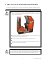
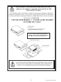
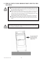
THE SHIPMENT METHOD DESCRIBED BELOW ONLY
APPLIES TO ‘MODEL 3’ BOARDS CONTAINED IN THE
FOLLOWING GAMES:
LOST WORLD, VIRTUA FIGHTER 3, SUPER GT, SEGA BASS FISHING, STRIKER 2
HARLEY DAVIDSON, RALLY 2, DAYTONA 2, DIRT DEVILS, HOUSE OF THE DEAD
2, OCEAN HUNTER, STAR WARS TRILOGY, ZOMBIE REVENGE, CRAZY TAXI, ARILINE PILOTS, 18 WHEELER
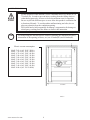
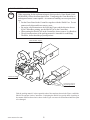
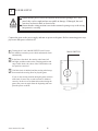
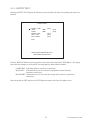
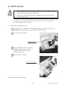
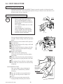
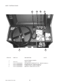
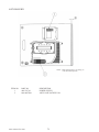
!!NEVER SHIP MODEL 3 / NAOMI GAME BOARDS
OUTSIDE OF CAGE!!
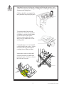
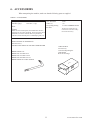
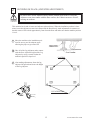
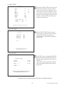
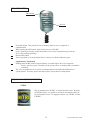
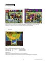
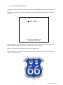
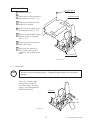
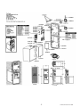
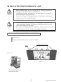
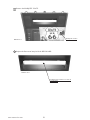
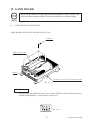
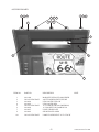
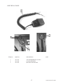
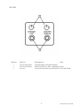
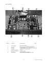
CARTON BOX
601-8928 (1)
Used for transporting the GAME BOARD.
{SUPPLIED WITH YOUR GAME}
DO NOT SHIP GAME BOARD WITHOUT
THIS BOX AS IT MAY DAMAGE THE GAME
BOARD AND VOID YOUR WARRANTY.
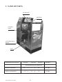
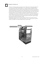
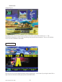
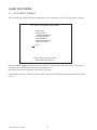
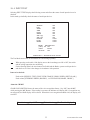
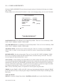
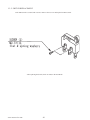
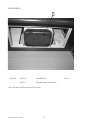
“CHECK SIDE” Display
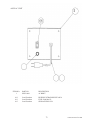
FILTER BOARD
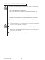
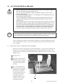
NO OTHER GAMES BOARDS ARE TO BE SHIPPED IN THE CAGE AS
THEY MAY BE DAMAGED BEYOND REPAIR. PLEASE SHIP THEM
WITHOUT CAGE PROPERLY PROTECTED DURING SHIPPING.
13
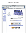
www.seuservice.com


![PLAS A O ]-OR](http://vs1.manualzilla.com/store/data/005852706_1-5db0b7ed584537f0e62af161fb124638-150x150.png)