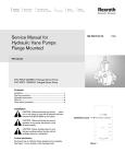
1
SSW40 USER’S MANUAL Spinning Wrench REFERENCE SSW40 REFERENCE DESCRIPTION Spinning Wrenches This document contains proprietary and confidential information which is the property of National Oilwell Varco, L.p, its affiliates or subsidiaries (all collectively referred to hereinafter as "NOV"). It is loaned for limited purposes only and remains the property of NOV. Reproduction, in whole or in part, or use of this design or distribution of this information to others is not permitted without the express written consent of NOV. This document is to be returned to NOV upon request or upon completion of the use for which it was loaned. This document and the information contained and represented herein is the copyrighted property of NOV. DOCUMENT NUMBER 50000835-MAN-001 www.nov.com VarcoBJ BV Nijverheidsweg 45 4879 AP Etten-Leur P.O. Box 17 4870 AA Etten-Leur The Netherlands Tel + 31-76-5083000 Fax + 31-76-5046000 www.nov.com REV A October 2008 User’s Manual SSW40 REFERENCE SSW40 REFERENCE DESCRIPTION Spinning wrench This document contains proprietary and confidential information which is the property of National Oilwell Varco, L.p., its affiliates or subsidiaries (all collectively referred to hereinafter as "NOV"). It is loaned for limited purposes only and remains the property of NOV. Reproduction, in whole or in part, or use of this design or distribution of this information to others is not permitted without the express written consent of NOV. This document is to be returned to NOV upon request or upon completion of the use for which it was loaned. This document and the information contained and represented herein is the copyrighted property of NOV. www.nov.com VarcoBJ BV Nijverheidsweg 45 4879AP Etten-Leur Tel: +31-76-5083000 Fax: +31-76-5046000 document number REV 50000835-MAN-001 A Document number Revision Page 50000835-MAN-001 A 2 of 58 Revision History A 18.12.2007 New Style - 01.08.2006 Issued for Implementation PGF BdP AK Rev Date Reason for issue Prepared Checked Approved Change Description Revision - www.nov.com Change Description First Issue PGF BdP AK Document number Revision Page 50000835-MAN-001 A 3 of 58 Table of Contents General Information . . . . . . . . . . . . . . . . . . . . . . . . . . . . . . . . . . . . . . . . . . . . . . . . . . . 5 Conventions . . . . . . . . . . . . . . . . . . . . . . . . . . . . . . . . . . . . . . . . . . . . . . . . . . . . . . . . . 5 Notes, Cautions, and Warnings . . . . . . . . . . . . . . . . . . . . . . . . . . . . . . . . . . . . . . . . 5 Illustrations . . . . . . . . . . . . . . . . . . . . . . . . . . . . . . . . . . . . . . . . . . . . . . . . . . . . . . . 5 Safety Requirements . . . . . . . . . . . . . . . . . . . . . . . . . . . . . . . . . . . . . . . . . . . . . . . . . . 5 Personnel Training . . . . . . . . . . . . . . . . . . . . . . . . . . . . . . . . . . . . . . . . . . . . . . . . . 6 Recommended Tools . . . . . . . . . . . . . . . . . . . . . . . . . . . . . . . . . . . . . . . . . . . . . . . 6 General System Safety Practices . . . . . . . . . . . . . . . . . . . . . . . . . . . . . . . . . . . . . . 6 Replacing Components . . . . . . . . . . . . . . . . . . . . . . . . . . . . . . . . . . . . . . . . . . . . . . 6 Routine Maintenance . . . . . . . . . . . . . . . . . . . . . . . . . . . . . . . . . . . . . . . . . . . . . . . 6 Proper Use of Equipment . . . . . . . . . . . . . . . . . . . . . . . . . . . . . . . . . . . . . . . . . . . . 6 Identification numbers . . . . . . . . . . . . . . . . . . . . . . . . . . . . . . . . . . . . . . . . . . . . . . . 6 Warning plates and labels . . . . . . . . . . . . . . . . . . . . . . . . . . . . . . . . . . . . . . . . . . . . 7 CE marking . . . . . . . . . . . . . . . . . . . . . . . . . . . . . . . . . . . . . . . . . . . . . . . . . . . . . . . 7 General specifications . . . . . . . . . . . . . . . . . . . . . . . . . . . . . . . . . . . . . . . . . . . . . . . . . 9 Description . . . . . . . . . . . . . . . . . . . . . . . . . . . . . . . . . . . . . . . . . . . . . . . . . . . . 9 Theory of operation . . . . . . . . . . . . . . . . . . . . . . . . . . . . . . . . . . . . . . . . . . . . . . 9 Specifications . . . . . . . . . . . . . . . . . . . . . . . . . . . . . . . . . . . . . . . . . . . . . . . . . . 9 Lubrication and maintenance . . . . . . . . . . . . . . . . . . . . . . . . . . . . . . . . . . . . . . . . . . 11 Recommended General Purpose EP grease . . . . . . . . . . . . . . . . . . . . . . . . . 11 Procedure maintenance & lubrication (in use) . . . . . . . . . . . . . . . . . . . . . . . . . . . 12 Lubrication . . . . . . . . . . . . . . . . . . . . . . . . . . . . . . . . . . . . . . . . . . . . . . . . . . . . 12 Inspection . . . . . . . . . . . . . . . . . . . . . . . . . . . . . . . . . . . . . . . . . . . . . . . . . . . . 12 Lubricator . . . . . . . . . . . . . . . . . . . . . . . . . . . . . . . . . . . . . . . . . . . . . . . . . . . . 13 Filter . . . . . . . . . . . . . . . . . . . . . . . . . . . . . . . . . . . . . . . . . . . . . . . . . . . . . . . . 14 Maintenance DO’s and DONT’s . . . . . . . . . . . . . . . . . . . . . . . . . . . . . . . . . . . 14 Drive Roller Replacement . . . . . . . . . . . . . . . . . . . . . . . . . . . . . . . . . . . . . . . . . . . 15 Procedure . . . . . . . . . . . . . . . . . . . . . . . . . . . . . . . . . . . . . . . . . . . . . . . . . . . . 16 Lower drive roller bearing replacement . . . . . . . . . . . . . . . . . . . . . . . . . . . . . . 16 Installation and commissioning . . . . . . . . . . . . . . . . . . . . . . . . . . . . . . . . . . . . . . . . 17 Installation procedure . . . . . . . . . . . . . . . . . . . . . . . . . . . . . . . . . . . . . . . . . . . . . . 17 Connecting air line. . . . . . . . . . . . . . . . . . . . . . . . . . . . . . . . . . . . . . . . . . . . . . 17 Operation . . . . . . . . . . . . . . . . . . . . . . . . . . . . . . . . . . . . . . . . . . . . . . . . . . . . . . . . . . 19 Normal usage . . . . . . . . . . . . . . . . . . . . . . . . . . . . . . . . . . . . . . . . . . . . . . . . . . . . 19 Tips on operation . . . . . . . . . . . . . . . . . . . . . . . . . . . . . . . . . . . . . . . . . . . . . . . 21 Handling the drill stem; tips and tricks . . . . . . . . . . . . . . . . . . . . . . . . . . . . . . . 21 Assembly and dis-assembly . . . . . . . . . . . . . . . . . . . . . . . . . . . . . . . . . . . . . . . . . . . 23 Gear train . . . . . . . . . . . . . . . . . . . . . . . . . . . . . . . . . . . . . . . . . . . . . . . . . . . . 23 Control Valves . . . . . . . . . . . . . . . . . . . . . . . . . . . . . . . . . . . . . . . . . . . . . . . . . 24 Adjustment Screw . . . . . . . . . . . . . . . . . . . . . . . . . . . . . . . . . . . . . . . . . . . . . . . . . 25 Removal . . . . . . . . . . . . . . . . . . . . . . . . . . . . . . . . . . . . . . . . . . . . . . . . . . . . . 25 Installation . . . . . . . . . . . . . . . . . . . . . . . . . . . . . . . . . . . . . . . . . . . . . . . . . . . . 26 Motor Removal . . . . . . . . . . . . . . . . . . . . . . . . . . . . . . . . . . . . . . . . . . . . . . . . 27 Motor maintenance . . . . . . . . . . . . . . . . . . . . . . . . . . . . . . . . . . . . . . . . . . . . . . . . 30 www.nov.com Document number Revision Page 50000835-MAN-001 A 4 of 58 Table of Contents Clearance . . . . . . . . . . . . . . . . . . . . . . . . . . . . . . . . . . . . . . . . . . . . . . . . . . . . Torque specifications . . . . . . . . . . . . . . . . . . . . . . . . . . . . . . . . . . . . . . . . . . . Bellows assembly & maintenance . . . . . . . . . . . . . . . . . . . . . . . . . . . . . . . . . Trouble shooting . . . . . . . . . . . . . . . . . . . . . . . . . . . . . . . . . . . . . . . . . . . . . . . . . . . . Initial checks, solves most problems . . . . . . . . . . . . . . . . . . . . . . . . . . . . . . . . Solutions . . . . . . . . . . . . . . . . . . . . . . . . . . . . . . . . . . . . . . . . . . . . . . . . . . . . . . . . Appendixes . . . . . . . . . . . . . . . . . . . . . . . . . . . . . . . . . . . . . . . . . . . . . . . . . . . . . . . . Storage, transport & decommissioning. . . . . . . . . . . . . . . . . . . . . . . . . . . . . . . . . Storage . . . . . . . . . . . . . . . . . . . . . . . . . . . . . . . . . . . . . . . . . . . . . . . . . . . . . . Returning to service . . . . . . . . . . . . . . . . . . . . . . . . . . . . . . . . . . . . . . . . . . . . Transport . . . . . . . . . . . . . . . . . . . . . . . . . . . . . . . . . . . . . . . . . . . . . . . . . . . . . Scrapping . . . . . . . . . . . . . . . . . . . . . . . . . . . . . . . . . . . . . . . . . . . . . . . . . . . . Torque values (US) for bolts . . . . . . . . . . . . . . . . . . . . . . . . . . . . . . . . . . . . . . Torque values (metric) for bolts . . . . . . . . . . . . . . . . . . . . . . . . . . . . . . . . . . . ATEX information . . . . . . . . . . . . . . . . . . . . . . . . . . . . . . . . . . . . . . . . . . . . . . . . . Drawings & Parts . . . . . . . . . . . . . . . . . . . . . . . . . . . . . . . . . . . . . . . . . . . . . . . . . . . . Parts lists . . . . . . . . . . . . . . . . . . . . . . . . . . . . . . . . . . . . . . . . . . . . . . . . . . . . . . . Hanger assembly . . . . . . . . . . . . . . . . . . . . . . . . . . . . . . . . . . . . . . . . . . . . . . Hanger assembly . . . . . . . . . . . . . . . . . . . . . . . . . . . . . . . . . . . . . . . . . . . . . . Gear train . . . . . . . . . . . . . . . . . . . . . . . . . . . . . . . . . . . . . . . . . . . . . . . . . . . . Controls and left body . . . . . . . . . . . . . . . . . . . . . . . . . . . . . . . . . . . . . . . . . . . Controls and left body . . . . . . . . . . . . . . . . . . . . . . . . . . . . . . . . . . . . . . . . . . . Filter, regulator, lubricator assembly . . . . . . . . . . . . . . . . . . . . . . . . . . . . . . . . Bellow assembly . . . . . . . . . . . . . . . . . . . . . . . . . . . . . . . . . . . . . . . . . . . . . . . Manifold assembly . . . . . . . . . . . . . . . . . . . . . . . . . . . . . . . . . . . . . . . . . . . . . Pneumatic system assembly . . . . . . . . . . . . . . . . . . . . . . . . . . . . . . . . . . . . . Air motor assembly . . . . . . . . . . . . . . . . . . . . . . . . . . . . . . . . . . . . . . . . . . . . . Control valves . . . . . . . . . . . . . . . . . . . . . . . . . . . . . . . . . . . . . . . . . . . . . . . . . Lift cylinder . . . . . . . . . . . . . . . . . . . . . . . . . . . . . . . . . . . . . . . . . . . . . . . . . . . 30 30 32 33 33 34 35 35 35 35 35 35 37 38 39 41 42 42 43 44 46 47 48 49 50 52 54 56 57 www.nov.com 1: General Information Document number Revision Page 50000835-MAN-001 A 5 of 58 General Information This manual contains installation, operation, maintenance and parts information. Information in this manual should enable qualified personnel to install, operate and troubleshoot this system. Every effort has been made to ensure the accuracy of the information contained herein. National Oilwell Varco (NOV) will not be held liable for errors in this material, or for consequences arising from misuse of this material. Conventions Notes, Cautions, and Warnings Notes, cautions, and warnings provide readers with additional information and advise the reader to take specific action to protect personnel from potential injury or lethal conditions. They may also inform the reader of actions necessary to prevent equipment damage. Please pay close attention to these advisories Note: The note symbol indicates that additional information is provided about the current topics. Caution: The caution symbol indicates that potential damage to equipment or injury to personnel exists. Follow instructions explicitly. Extreme care should be taken when performing operations or procedures preceded by this caution symbol. Warning: The warning symbol indicates a definite risk of equipment damage or danger to personnel. Failure to observe and follow proper procedures could result in serious or fatal injury to personnel, significant property loss, or significant equipment damage. Illustrations Illustrations (figures) provide a graphical representation of equipment components or screen snapshots for use in identifying parts or establishing nomenclature, and may or may not be drawn to scale. For component information specific to your application, see the technical drawings included with your NOV documentation. Safety Requirements NOV equipment is installed and operated in a controlled drilling rig environment involving hazardous situations. Proper maintenance is important for safe and reliable operation. Procedures outlined in NOV manuals are the recommended methods of performing operations and maintenance. Caution: To avoid injury to personnel or equipment damage, carefully observe requirements outlined in this section. www.nov.com Document number Revision Page 50000835-MAN-001 A 6 of 58 1: General Information Personnel Training All personnel performing installation, operations, repair, or maintenance procedures on the equipment, or those in the vicinity of the equipment, should be trained on rig safety, tool operation, and maintenance to ensure their safety. Caution: Personnel should wear protective gear during installation, maintenance, and certain operations. Recommended Tools Service operations may require the use of tools designed specifically for the purpose described. NOV recommends that only those tools specified be used when stated. Ensure that personnel and equipment safety are not jeopardized when following service procedures or using tools not specifically recommended by NOV. General System Safety Practices The equipment discussed in this manual may require or contain one or more utilities, such as electrical, hydraulic, pneumatic, or cooling water. Caution: Read and follow the guidelines below before installing equipment or performing maintenance to avoid endangering exposed persons or damaging equipment. Isolate energy sources before beginning work. Avoid performing maintenance or repairs while the equipment is in operation. Wear proper protective equipment during equipment installation, maintenance, or repair. Replacing Components Verify that all components (such as cables, hoses, etc.) are tagged and labeled during assembly and disassembly of equipment to ensure correct installment. Replace failed or damaged components with genuine NOV parts. Failure to do so could result in equipment damage or injury to personnel. Routine Maintenance Equipment must be maintained on a routine basis. See the service manual for maintenance recommendations. Caution: Failure to conduct routine maintenance could result in equipment damage or injury to personnel. Proper Use of Equipment NOV equipment is designed for specific functions and applications, and should be used only for its intended purpose. Identification numbers You will find the serial number of the tool stamped into the body. www.nov.com Document number Revision Page 1: General Information 50000835-MAN-001 A 7 of 58 Warning plates and labels WARNING: Warning plates and labels must be present on the Spinning Wrench. Do not remove them. When a label or warning plate has disappeared, it must be replaced. CE marking The SSW40 complies with the Machinery Directive 98/37/EC and Directive 94/9/EC “Equipment and protective systems in potentially explosive atmospheres”. The marking is as follows: Ex II 2GT5 WARNING: Care should be taken to avoid creating possible ignition sources, like sparks, due to improper use of the tool in combination with other equipment. www.nov.com Document number Revision Page 50000835-MAN-001 A 8 of 58 1: General Information www.nov.com Document number Revision Page 2: Specifications 50000835-MAN-001 A 9 of 64 General specifications Description The Varco SSW-40 spinning wrench is a pneumatically-powered tool capable of spinning drill pipe and collars from 31/2” to 91/2” (89 - 241 mm) OD. . Theory of operation A typical spinning procedure is as follows: First, position the wrench vertically with the vertical positioning control to a point about one foot above the tool joint, or just above the pipe upset. The spinning wrench is now swung onto the pipe and the clamp control pushed to clamp the drive rollers against the pipe. Next, the throttle control is pushed to spin in or pulled to spin out. Specifications Part numbers 10246 (less rollers) 12035 (3 1/2” rollers) Partnumbers Roller assemblies 12045 (4 1/2” rollers) 12050 (5” rollers) 12055 (5 1/2” rollers) Specifications Range Type Air pressure RPM (5” O.D. pipe) Stall torque (5” O.D. pipe) Weight: 250cfm (118 dm3/ s) 0-120 1,100 ft-lbs (1,493 Nm) 780 lbs. (353 kg) Height 17.2” (437 mm) Length 55” (1397 mm) Width 22.2” (564 mm) Air consumption www.nov.com 31/2” to 91/2” (89-241 mm) O.D. Drill pipe and collars 90-125 psi. (650-860 KPa) Document number Revision Page 50000835-MAN-001 A 10 of 58 2: Specifications Vertical positioning cylinder Level adjustment screw Back up line Throtle control Clamp control Pipe size adjustment Vertical positioning control SSW40 Fig 1-1 www.nov.com Document number Revision Page 3: Lubrication and maintenance 50000835-MAN-001 A 11 of 64 Lubrication and maintenance Recommended General Purpose EP grease Lube code description Above -20° C Below -20° C Castrol MP grease n/a Chevron Avi-Motive Avi-Motive W Exxon Lidok EP2 Lidok EP1 Gulf Gulfcrown EP2 Gulfcrown EP1 Mobil Mobilux EP2 Mobilux EP1 Shell Alvania EP2 Alvania EP1 Texaco Multifak EP2 Multifak EP1 Union Unoba EP2 Unoba EP1 WARNING: Make sure that all pneumatic supply is isolated before ANY work is carried out to the Spinning Wrench. Shut off the Power Unit / Close the valves. WARNING: Do not use casing and tubing lubricant for lubricating the SSW40. Thread compound (pipe dope) must be applied to the tooljoint every time it is made up. www.nov.com Document number Revision Page 50000835-MAN-001 A 12 of 58 3: Lubrication and maintenance Procedure maintenance & lubrication (in use) Lubrication Item Description Lube points Lubricant Frequency 1 2 3 4 5 6 7 (See fig.3.4) Lubricator Air line Gear case Drive roller bearings Adjustment screw Air hose swivel Adjustment handle 1 1 2 8 2 1 1 every trip every rig-up 3 months every trip every trip every trip every trip SAE 10 oil SAE 10 oil Drain and refill with SAE 90 oil* Multipurpose grease Multipurpose grease Multipurpose grease Multipurpose grease *Below 320 F / 0° C, use SAE 10 oil 2 places 2 2 5 1 1 place 6 3 7 2 places 4 Figure 3.4 Inspection Item Description Action Frequency 1 Drive rollers Monthly 2 Drive rollers 3 Quick exhaust valve Check adjustment Check for wear. With the tool clamped on the pipe, see that there is no contact between the bodies and the pipe. Clean muffler Daily When required www.nov.com 3: Lubrication and maintenance Document number Revision Page 50000835-MAN-001 A 13 of 64 Lubricator Procedure Fill lubricator with SAE 10 oil Reservoir can be filled with-out turning of the inlet supply pressure as follows: Close air shut-off valve by turning clock wise Remove self venting fill plug Fill to bottom of sight tube with lubricating oil (appr. 80 to 150 SSU at 10°F e.g. SAE 5 or 10) Drip rate is factory set and must not be changed Replace fill plug hand tight and fully open air valve If replacing filter, set drip rate according to instructions given with unit. CAUTION: Avoid exposing plastic bottles to any chemicals that would deteriorate plastic, such as solvents, thinners and carbon tetrachloride. www.nov.com Document number Revision Page 50000835-MAN-001 A 14 of 58 3: Lubrication and maintenance Filter Procedure Shut off power supply and open cock valve to vent pressure Remove hex nut, base and bowl. Bowl can be cleaned with mild soap and water or kerosene Do not use solvents, thinner or carbon tetrachloride. Unscrew baffle nut and baffle plate and remove element and element retainer. Install new element and element retainer. Screw baffle plate up hand tight and secure with baffle nut, wrench tight. Maintenance DO’s and DONT’s DO’s Lubricate as indicated acc. to procedures Keep adequate air pressure on system Keep roller in adjustment acc. to procedure DONT’s Never paint over moving parts or grease fittings. Avoid contamination of air lines Avoid dry over-oiled lubricator Never restrict air flow Never use equipment that is not operating properly www.nov.com 3: Lubrication and maintenance Document number Revision Page 50000835-MAN-001 A 15 of 64 Drive Roller Replacement 8, 9 10 11 16 17 18 15 14 19 21, 22 20 13 12 11 7 3, 4 5, 6 1, 2 www.nov.com Figure 4.1 Document number Revision Page 50000835-MAN-001 A 16 of 58 3: Lubrication and maintenance Procedure 1. Remove cover (1) right hand or (2) left hand. 2. Only for right side, Disconnect hoses from valve assembly and remove manifold. 3. Remove drain plug (3) right hand or (4) left hand with gear case (5) right hand or (6) left hand and gasket (7). NOTE: All gears are retained by bearing retainers, allowing removal of the gear case with the tool in any position. 4. Remove bearing cover (8) right hand or (9) Left hand and bearing cover gasket (10). 5. Remove bearing retainer (11) on top and bottom, this releases roller gear (12), spacer shield (13), and drive roller gear keys (14) from bottom of drive roller shaft (15). 6. Push drive roller shaft (15) upwards along with upper roller bearing (16), spacer/shield (17), O-ring (18), and drive roller key (19), using a soft mallet if necessary. 7. Slide drive roller (20) out from inside body (21) right hand or (22) left hand. 8. Repeat steps 5. thru 7. for secondroller in each side. 9. Reverse procedure to re-assemble, using care to avoid damaging bearing seals. Torque bolts for bearing retainer (11) to 15-20 ft. Lbs. NOTE: Always use new O-rings and gasket upon Reassembly. Lower drive roller bearing replacement 10. Repeat steps 1. thru 7. 11. Remove lower spacer/shield (1) with O-ring (2). 12. Remove internal retaining ring (3) and push roller bearing (4) upward to remove. 13. Reverse procedure to re-assemble. Use care to avoid damaging the bearing seals 2 1 3 4 www.nov.com 4: Installation and commissioning Document number Revision Page 50000835-MAN-001 A 17 of 64 Installation and commissioning Installation procedure Attach a 1/2” or 5/8” cable to the mast that will allow a free, easy swing around the wellbore. The higher the fixed line, the easier it will be to move the wrench onto the pipe. Attach the cable at a cross member about 2,5 feet from the drill pipe centerline (as shown in fig. 2.1) and position the wrench across from the driller where the chainman would normally stand. With the lift cylinder at the midpoint of its stroke, suspend the SSW-40 approximately 5 feet above the floor. This will allow 12” of vertical travel up or down. Attach TWO back-up cables to the shackles provided at the rear of the wrench to restrict rotational movement to 12” in either direction. Do not cross cables. WARNING: If only one back-up line is attached, the wrench can swing into the operator causing injury. Connecting air line. The SSW-40 requires approximately 250 cfm air flow at 90 to 125 psi air pressure. An air regulator is included with the tool to prevent damage from excessive air pressure. NOTE: During installation, use as few fittings as possible and route the air line direct from the air supply, keeping distance as short as possible. www.nov.com Run a 11/5” air supply line up to the rig floor in a protected area easily accessable for maintenance. Install a 11/5” shutt-off valve to the air supply line (as shown) to allow maintenance of the tool. Attach the filter end of the filter/regulator/ lubricator assembly to shutt-off valve. Connect the 25 foot air hose assembly provided, to the lubricator end of the filter/regulator /lubricator assembly. Blow out air line to remove any trapped moisture and debris. Pour 1/2 pint of SAE 10 oil into 25 foot hose, then connect to spinning wrench swivel fitting. Level tool with the rig floor using the hanger adjustment screw provided. Document number Revision Page 50000835-MAN-001 A 18 of 58 4: Installation and commissioning 21/2 ft Caution The spinning wrench must be level at point of contact with pipe before clamping. Fixed line Hangar adjustment screw* Vertical positioning cylinder* (air) Back-up lines Lubricator* Air regulator* Approx. 5ft. 11/4“ hose Filter* Shutoff valve 11/2” Air line Figure 2.1 * Supplied with spinning wrench www.nov.com Document number Revision Page 5: Operation 50000835-MAN-001 A 19 of 64 Operation Normal usage The spinning wrench is designed to: Spin in and spin out various types of tubing and casing CAUTION: Back up lines must be attached to limit rotational movement to 1 foot (0.3m) in each direction. Adjust the SSW-40 to the appropriate pipe size by pulling the adjustment screw and turning it to engage the socket. Turn the adjustment handle counterclockwise to open the bodies or clockwise to close the distance between the bodies. Proper clearance is 1/2” between the front rollers and the pipe or collar being used. NOTE: Check to be sure that back-up lines are properly attached (see Section 2) Swing the SSW-40 onto the pipe about 12” above the tool joint. Do not run the tool on the pipe upset or tool joint. To clamp onto the pipe: push the clamp control. To spin pipe, position lockout to spin in or spin out as required. The lockout prevents spinning pipe in the wrong direction. Push the throttle control to spin in or pull to spin out. To unclamp from pipe, pull the clamp control and swing wrench away. To position the SSW-40 vertically, push the vertical positioning control to move the tool up or pull to move down. 1 Upset Tool joint Figure 3.3 www.nov.com Document number Revision Page 50000835-MAN-001 A 20 of 58 1 5: Operation /2” Drive roller Drive roller Motor Motor Retractable adjustment arm Figure 3.1 Figure 3.2 Vertical positioning cylinder Level adjustment Back-up Throttle Clamp control Vertical positioning Pipe size www.nov.com 5: Operation Document number Revision Page 50000835-MAN-001 A 21 of 64 Tips on operation 1. Pin should be stabbed into the box as vertical as possible. Spinning wrench can not spin an improperly aligned connection 2. Spin pin into box until pin and box are just shouldered together; at this point stop and torque joint with the torque wrench. Do not use the spinning wrench to torque joints. 3. Keep clamping arms adjusted. Slipping rollers will cause rollers to wear. If drive rollers start to slip on the pipe, check the pressure roller adjustment and adjust equally on both sides. See adjustment procedure. 4. Replace worn Drive rollers. If the drive rollers start to slip and the roller arms have been adjusted to maximum, this may indicate drive rollers require replacement. Handling the drill stem; tips and tricks Picking up and laying down the drill stem Use thread protectors when available. When threads and shoulders are unprotected, do not permit the tool joints to strike steel surfaces such as walks, stairs, steel floors, or machinery. Use wood surfaces where the tool joint may hit. Cleaning and lubrication (thread compounds) Pin and box threads and shoulders should be thoroughly cleaned. Use solvent and wipe dry with a clean rag. Inspect carefully for any burrs or nicks on the shoulders or threads. Damaged connections should never be run in the hole. After cleaning, apply tool joint thread compound to threads and shoulders with a round, stiff bristle brush. Use thread compounds containing 40% to 50% by weight of finely powdered metallic zinc. CAUTION: Never, under any circumstances, use casing and tubing lubricant. Thread compound must be applied to the tool joint every time it is made up. Stabbing and spinning the drill stem Do not allow the ends of the pin to strike the box shoulders. the shoulder must not be nicked or other wise damaged. Before spinning the pipe, make sure connections are in alignment. Do not rotate the pipe too fast, especially when wobbling or binding occurs. Extra care is necessary when a power operated spinner is used. Making up the drill stem (torque) www.nov.com Torque measuring equipment must be used. When using tongs, it is important that line pull be measured when the line is at right angles or 90° to the tong handle. When applying line pull, do not jerk the tongs. Over-torque can be just as damaging as under-torque. Use both tongs (when tongs are used) when making up tool joints. Do not make up pipe using spinners only. Torquing devices must be used. Document number Revision Page 50000835-MAN-001 A 22 of 58 5: Operation Breaking in new connections Initial make up is most critical and extra care is essential for long trouble-free service. Follow these steps: Inspect threads and shoulder for any damage. Clean and lubricate as indicated above. Walk in or slowly rotate joints together. Makeup to recommended torque. Breakout and slowly spin out. Breaking and spinning out the drill stem When breaking out the joint, use both tongs (when using tongs). Always follow these steps: Do not let the end of the pipe strike the box shoulder. Come out of the hole on a different break each trip so that every connection can be periodically broken and its condition and torque checked. When standing the pipe back, be sure the set back area is clean where the pin will rest. www.nov.com 6: Assembly Document number Revision Page 50000835-MAN-001 A 23 of 64 Assembly and dis-assembly WARNING: Make sure that all pneumatic lines are isolated before ANY work is performed on the Spinning wrench NOTE: All assembly and disassembling should be performed in a dry, clean area. NOTE: For assembly, use all new O-rings. seals and gaskets and lubricate at time of assembly only. When applying Locktite to threaded surfaces, all threads must be clean and free of grease and grit. Gear train The Gear Train on the SSW-40 is simple in design requiring only a pair of snap ring pliers to remove gear retaining rings and a bearing press to change needle bearings. Idle gear shafts are screwed into the body. NOTE: Do not use hammer to install needle bearings Figure 4.3 www.nov.com Document number Revision Page 50000835-MAN-001 A 24 of 58 6: Assembly Control Valves The control valves are all of the same basic type requiring no special tools or instruction to service. Use the exploded drawing below and the parts list at the back of the book to replace seals and gaskets. www.nov.com Document number Revision Page 6: Assembly 50000835-MAN-001 A 25 of 64 Adjustment Screw Removal 1. Remove extension spring (1). Obtain a 6"to 8” piece of 3/8"-16"allthread with a hex nut, to use as a tool. Using tool, relax tension on extension spring (1). Pass threaded end of tool through eye of bracket (2) and screw into 3/8"thread on end of the Extension spring (1). Run nut on tool up to bracket (2). Remove screw (3). Loosen nut on tool until extension spring (1) is Relaxed. Now remove remaining hardware. See figure 6.3, remove bellows bolt (18) of Right side , untight screw on bottom of bellow. Disconnect hose from valve quick exhaust muffler. 2. Place the entire tool on bench or where the work has to be done. Remove the 8 screw holding the pivot block covers (4) in place. 3. Remove the hanger rod (5), hanger (6), and lift cylinder (7) as an assembly with their attaching hardware. Motor Lift valve Clamp Figure 4.4 www.nov.com Document number Revision Page 50000835-MAN-001 A 26 of 58 6: Assembly 4. Unfasten capscrew (8) and grease seal cap(9). 5. Remove knurled knob(10). 6. Disconnect hoses of airmotor right side. 7. Using the adjustment handle (11), turn the adjustment screw (12) counterclockwise until it is free of the right pivot block (13). 8. Separate the bodies and continue to turn the adjustment screw (12) until it is free (approx.2 turns). Installation 1. Turn adjustment screw (12) 11/4 turns into the left pivot block (14). 2. Put left and right frame opposite position. Be sure that the adjustment screw (12) is centered between the pivot blocks (13&14). 3. Push right frame against adjustment screw (12). Place adjustment handle(11) in adjustment screw (8), and pull handle (11) as far tru as possible. 4. Turn knurled knob(10) in adjustment handle (11). 5. Be sure that adjustment screw not turns. 6. Turn adjustment handle(11) assembly clockwise so, left and right frame will come together. 7. Be sure that the adjustment screw (12) is centered between the pivot blocks (13&14) within 1/8" maximum. 8. Place the hanger rod (5), hanger (6) and lift cylinder (7) as an assembly with their attaching hardware. Put the 8 screws holding the pivot block covers (4) back in place. Lockwire them by 2. 9. Mount cap screw (8) and grease sealcap(9). 10. Connect hoses to airmotor right side. 11. See figure 6.3, place bellows bolt (18) of Right side , mount screw on bottom of bellow. 12. Place extension spring (1) back on frame. 13. Connect hose to valve quick exhaust muffler. Nut Allthread Figure 4.5 3 2 1 www.nov.com Document number Revision Page 6: Assembly 50000835-MAN-001 A 27 of 64 6 4 5 7 8 11 13 14 12 9 10 Figure 4.6 Motor Removal 1. Refer to adjustment screw removal procedure, step 4.5.1.1, and remove extension spring. 2. Pull out adjustment handle and turn until adjustment screw is fully extended for easy access. 3. Remove and label right motor hose assembly (1) and left motor hose assembly (2). 4. If left motor (3) is to be removed, remove motor valve (4) from inboard and outboard left motor hose assemblies (5 & 6). 5. Remove cover (7) right hand or (8) left hand. 6. Only for right side, disconnect hoses from valve assembly and remove manifold. 7. Remove drain plug (9) right hand or (10) left hand with gear case (11) right hand or (12) left hand and gasket (13). 8. Remove roller compound gear (14) and 9. Motor compound gear (15). This releases moter gear (16) and motor gear key(17). NOTE: Mark orientation of motor gear key (17) for reassembly. The tab on one end should rest on top of motor gear(16). 10. Remove lockwire and 9 screws. Motor (3) is now free to come out through side opening in body, or between the bodies. 11. Reverse procedure to re-install motor (3). 12. Torque screws to 8-10 ft. lbs. Be certain to re-lockwire the 9 screws (See fig 5.3). www.nov.com Document number Revision Page 50000835-MAN-001 A 28 of 58 6: Assembly 1 3 5 2 4 Figure 5.1 Lockwir Screw Figure 5.3 A www.nov.com Document number Revision Page 6: Assembly 50000835-MAN-001 A 29 of 64 3 A 17 16 15 14 13 9, 10 11,12 Figure 5.2 www.nov.com Document number Revision Page 50000835-MAN-001 A 30 of 58 6: Assembly Motor maintenance 1. Motor maintenance is straightforward and requires no special instructions other than the following: 2. The bearing clamp screw (1) has left hand threads. Do not remove unless it is necessary, as the rotor bearing (9) must then be re-shimed. 3. When replacing vanes (2), remove the rotor (3) and liner (4) as a unit, then remove the retaining ring (5), pinion gear (6). Lower end plate (7) and liner to expose the vanes. 4. If the upper end plate (8) is removed, the rotor (3) to rotor bearing (9) clearance must be checked and reset if necessary by shimming between the rotor bearing and the rotor bearing spacer (10). Clearance Rotor to rotor bearing clearance is 0.0015” to 0.0020”. Torque specifications Item Qty Torque 1 1 33-38 ft-lbs / 45 - 52 Nm 11 5 150-175 in-lbs / 203-237 Nm 12 4 18-20 ft-lbs / 25.5 - 27 Nm 13 4 150-175 in-lbs / 203-237 Nm www.nov.com Document number Revision Page 6: Assembly 50000835-MAN-001 A 31 of 64 11 7 12 6 5 1 13 9 8 4 shim 10 3 Figure 5.4 13 www.nov.com 2 Document number Revision Page 50000835-MAN-001 A 32 of 58 6: Assembly Bellows assembly & maintenance Follow the exploded drawing (figure 5.5) when servicing the bellows assembly. NOTE: If clevis link (1) is removed, be sure to re-attach long ends to left hand cap (2). When bolting bellows (3) to end caps, bring all nuts up fingertight, then use criss-cross pattern to tighten bellow bolts. Do not allow any nut to get more than 2 turns ahead of the rest. WARNING: The unit must not be pressurized until it is installed in tool. 1 2 Figure 5.5 3 www.nov.com 7: Trouble shooting Document number Revision Page 50000835-MAN-001 A 33 of 64 Trouble shooting Prior to trouble shooting a problematic Spinning wrench, carry out the following checks to prevent making loopholes in solving the problem. When problems cannot be solved please contact an authorized Varco BJ repair facility. WARNING: Make sure the pressure line valve is fully opened before pressurising the Spinning Wrench Initial checks, solves most problems 1. Is air pressure available? 2. Check that the power supply is at least 90 Psi / 620 KPa. 3. Check the mufflers are not blocked with mud etc. 4. Check the functioning of the control valve www.nov.com Document number Revision Page 50000835-MAN-001 A 34 of 58 7: Trouble shooting Solutions Symptom Probable cause Solution Wrench fails to spin or clamp onto drill pipe No air pressure Check general symptoms Wrench fails to clamp onto drill pipe. No air pressure Check general symptoms Dirty or clogged air exhaust mufflers Clean and/or replace mufflers Faulty clamp valve Replace valve or install seal kit if unit indicates leaky seals. Kit shown in parts list. Pressure arms out of adjustment. Re-adjustment arms as indicated in chapters “installation and Operations” Drive rollers are worn and will not contact pipe adequately Check rollers and replace as required Drive roller gears, idler gears and/or gear is worn excessively Check these gears as noted in the disassembly procedures and inspect all affected parts for excessive wear and replace as required. Wrench is not equipped with check valve. This valve prevents pressure decay in the air lines. Check if wrench is equipped with check valve. If not, install. Insufficient air pressure See general symptoms Throttle control handle is frozen Lubricate control handle front and back Drive shaft or drive key is broken. Possible damage to drive gear and idler gear Disassemble wrench and replace shaft and /or gears. It is recommended to replace all seals and check bearings when replacing gears at all times. Air motor is frozen up. Remove air motor and check internal mechanisms and replace damaged components. Cap screw and lock washer used to retain main drive gear on air motor has come loose and has caused misalignment and damage. Lower gear box as indicated in chapter “ASSEMBLY”. and check drive gear. If the cap screw has come loose it is recommended that the cap screw is replaced. Pressure roller is worn Replace pressure rollers and bearings Pressure rollers arms have a metal fatigue Check both arms for cracks between the drive roller and pressure mounting holes. Spool valve has leaking seals and will not hold required pressure Replace valve and or seals. Wrench drive rollers slip on drill pipe Air motor does not operate or operates slowly and drive rollers will not rotate. Wrench slips on drill pipe but drive rollers and motor operate. www.nov.com 8: Appendixes Document number Revision Page 50000860 A 35 of 64 Appendixes Storage, transport & decommissioning. Storage Main unit should be palletized for indoor storage. A cargo container would be appropriate for indoor/ outdoor storage. Every attempt should be made to avoid wide variations in temperature and high humidity. The preferred environment would be clean and dry at 60°F (16° C) ambient. If high humidity is unavoidable, 70° F (21° C) is recommended. All exposed, not painted metal surfaces, are coated with a rust preventative at the factory prior to shipment. However, these surfaces should be checked periodically (when fulfilling the above conditions once per 3 months is recommended) to be sure that no corrosion is taking place. All openings should be covered to prevent water or dust from entering. We do not recommend the use of silica or a dehydrating agent. When the Spinning wrench is not being used for a longer period (like storage) the following steps should be carried out: Clean Spinning wrench Grease Spinning wrench as described. Grease all blank parts. Use an extreme pressure, multi-purpose, lithium based grease of No. 1 or No. 2 consistency. Clean and cap pneumatic Quick Disconnect Couplings. Recommended rust preventative (slushing compound) for bare metal surfaces is Valvoline Tectyl or equivalent. Pour a pint (1/2 l) of SAE 10 lube oil in hose and run through air motor while actuating air cylinder, to ensure coating internal components with oil. Drain gear case and replace with 2 quarts (1.9 l) of SAE30 oil. Heavy application of grease at all grease nipples Returning to service Check that the lubricator is clean and filled with SAE10 oil. Check filter is clean and water has been drained Check lubricator is located between the regulator and the wrench Drain and refill gear case with 2 quarts (1,9 l) SAE 90 transmission oil. Blow air line out before connecting to wrench Transport The best way of transporting the Spinning wrench is in its original crate. Use oiled paper and seal the box with plastic to prevent leaking when stored outside. Secure the top safely. Scrapping The tool contains grease, steel, rubbers, plastic, stainless steel or mild steel and several assembled components from undefined consistency or mixtures. The tool can be contaminated with mud. When the tool is taken out of service it is recommended to disassemble the tool in a place where drainage for waste fluids is possible www.nov.com Document number Revision Page 50000860 A 36 of 58 8: Appendixes . WARNING: Any fluids, mud and grease are unsafe when touched by the skin. Always wear gloves and safety goggles when disassembling the tool. Clean the tool with a steam cleaner. Remove all other parts. Carry off to proper place for final storage or destruction www.nov.com Document number Revision Page 8: Appendixes 50000860 A 37 of 64 Torque values (US) for bolts Dia. Threads per inch Bolts Lubricated with Light Machine Oil Grade 8 Bolts lubricated with Anti-seize compound Grade 8 Min. Torque (ft lb) Max. Torque (ft lb) Clamp force (lb) Min. Torque (ft lb) Max. Torque (ft lb) Clamp force (lb) Coarse Thread Series, UNC 1 /4 ” 20 11.4 12.6 2860 8.6 9.5 2860 5 /16” 18 24 26 3720 17.8 19.7 3720 3 /8 ” 16 43 47 7000 32 35 7000 7 /16” 14 67 74 9550 50 55 9550 1 /2 ” 13 105 116 12750 78 87 12750 9 /16” 12 143 158 16100 107 118 16100 5/ 8” 11 209 231 20350 157 173 20350 3 /4 ” 10 361 399 30100 271 299 30100 7 /8 ” 9 570 630 41600 428 473 41600 8 855 945 54500 641 709 54400 1 1 /8 ” 7 1216 1344 68700 912 1008 68700 1 1 /4 ” 7 1729 1911 87200 1297 1433 87200 1 3 /8 ” 6 2261 2499 104000 1696 1874 104000 1 6 3002 3318 126500 2252 2489 126500 1” 1 /2 ” Tensile Strength = 150,000 psi to 1” dia. Proof Strength = 120,000 psi Dia. Bolts Lubricated with Light Machine Oil Grade 8 Bolts lubricated with Anti-seize compound Grade 8 Min. Torque (ft lb) Max. Torque (ft lb) Clamp force (lb) Min. Torque (ft lb) Max. Torque (ft lb) Clamp force (lb) 28 13.3 14.7 3280 10 11 3280 Threads per inch Fine Thread Series, UNF 1 /4 ” 5/ 16” 24 24 26 5220 17.8 19.7 5220 3/ 8” 24 48 53 7900 36 39 7900 /16” 20 76 84 10700 57 63 10700 2” 20 114 126 14400 86 95 14400 /16” 18 162 179 18250 121 134 18250 18 228 252 23000 171 189 23000 4” 16 399 441 33600 299 331 33600 /8 ” 7 1/ 9 5/ 8” 3/ 7 14 627 693 45800 470 520 45800 1” 14 950 1050 59700 713 788 59700 1 1 /8 ” 12 1368 1512 77000 1026 1134 77000 1 1 /4 ” 12 1900 2100 96600 1425 1565 96600 3/ 8” 12 2584 2856 118400 1938 2142 118400 1 1 /2 ” 12 3382 3738 142200 2537 2804 142200 1 Tensile Strength = 150,000 psi to 1” dia. Proof Strength = 120,000 psi www.nov.com Document number Revision Page 50000860 A 38 of 58 8: Appendixes Torque values (metric) for bolts Bolts Lubricated with Light Machine Oil Grade 8 Dia meter Threads per Min. inch Torque (Nm) Bolts lubricated with Anti-seize compound Grade 8 Max. Torque (Nm) Clamp force (N) Min. Torque (Nm) Max. Torque (Nm) Clamp force (N) Coarse Thread Series, UNC 1 /4 ” 20 15.5 17.1 12870 11.7 12.9 12870 5 /16” 18 32.6 35.4 16740 24.2 26.8 16740 3 /8 ” 16 58.5 64 32500 43.5 47.6 31500 7 /16” 14 91.1 100.6 42980 68 92.5 42980 1 /2 ” 13 143 158 57380 106 118 57380 9 /16” 12 195 215 72450 145.5 160 72450 5/ 8” 11 284 314 91580 213.5 235 91580 3 /4 ” 10 491 542 135450 368 407 135450 7 /8 ” 9 775 857 187200 582 643 187200 8 1163 1285 245250 872 965 245250 1” 1 1 /8 ” 7 1654 1828 309150 1240 1370 309150 1 1 /4 ” 7 2351 2598 382400 1764 1949 392400 1 3 /8 ” 6 3075 3398 468000 2306 2549 468000 1 6 4082 4512 569250 3062 3385 569250 1 /2 ” Bolts Lubricated with Light Machine Oil Grade 8 Dia meter Threads per Min. inch Torque (Nm) Bolts lubricated with Anti-seize compound Grade 8 Max. Torque (Nm) Clamp force (N) Min. Torque (Nm) Max. Torque (Nm) Clamp force (N) Fine Thread Series, UNF 1 /4 ” 28 18.1 20 14760 13.6 15 14760 5 /16” 24 32.6 35 23490 24.2 26.8 23490 3 /8 ” 24 65.3 72 35550 49 53 35550 7 /16” 20 103 114 48150 77.5 86 48150 1 /2 ” 20 155 171 64800 117 129 64800 9 /16” 18 220 239 82130 165 182 82130 5/ 8” 18 310 343 103500 232 257 103500 3 /4 ” 16 542 600 151200 406 450 151200 7 /8 ” 14 853 943 206100 639 707 206100 14 1292 1428 268650 970 1071 268650 1 1 /8 ” 12 1860 2056 346500 1396 1542 346500 1 1 /4 ” 12 2584 2856 434700 1938 2128 434700 3 1 /8 ” 12 3514 3884 532800 2635 2913 532800 1 12 4599 5083 639900 3450 3813 639900 1” 1 /2 ” www.nov.com Document number Revision Page 8: Appendixes 50000860 A 39 of 64 ATEX information Over a limited period the temperature of the SSW 40 was measured while it was running on the test bench, under normal operation conditions. 4 points where measured (degrees Celcius) The bellow The lift cylinder The spinners while spinning in The spinners while spinning out 45 40 35 30 Bellow Lift Cyl Spin in Spin uit 25 20 15 10 5 36 31 26 21 16 11 6 1 0 Conclusions: The maximum reached temperature is 42°C / 108°C. Most of the lines have reached the point that they are not climbing any longer. The spin in temperature is still increasing. However, this temperature is small compared to the temperature of the bellow, which line has not increased over the 4 last measurements. It is not expected the Spin-in temperature will exceed the Bellow temperature. www.nov.com Document number Revision Page 50000860 A 40 of 58 8: Appendixes www.nov.com 9: Drawings Drawings & Parts www.nov.com Document number Revision Page 50000835-MAN-001 A 41 of 58 Document number Revision Page 50000835-MAN-001 A 42 of 58 9: Drawings Parts lists Hanger assembly 2 1 7 3 6 4 8 5 17 9 6 20 10 21 14 23 7 25 13 15 11 12 16 26 27 Figure 6.1 24 19 18 22 www.nov.com Document number Revision Page 9: Drawings 50000835-MAN-001 A 43 of 58 Hanger assembly Item Qty Description 1 1 Lift cylinder assembly 2 1 3 4 5 6 7 8 1 1 1 2 2 1 1 2 2 8 8 2 2 2 2 2 2 2 2 1 2 2 1 2 2 1 1 1 1 1 1 1 1 2 9 10 11 12 13 14 15 16 17 18 19 20 21 22 23 24 25 26 27 www.nov.com 900 Part no. 75341 0 Elbow, , ext. pipe/37 Filter Hanger Hanger rod Support washer External retaining ring, Adjustment screw, Hex-jam nut Pivot block cover Pivot block cover gasket Hex Head cap screw Regular lock washer Stop Hex head cap screw Regular lock washer Machined hanger block Straight grease fitting Thrust washer Hanger block bushing Top-Counter block Cap screw Socket head cap screw Regular lock washer Grease seal cap Socket Head cap screw Regular lock washer O-Ring O-Ring Adjustment assy. handle Knurled knob Right pivot block Left pivot block Adjustment screw Adjustment screw sleeve External retaining ring 56506-8-4-5 75937 76543 74242 76256 53600-156 50012-24-C8 50312-C 76230 76231 50006-10-C8D 50906- C 74241 50010-10-C8 50910-C 74610 53201 74611 74612 74584 74608 50103-6-C 50903-C 74607 50103-6-C 50903-C 51300-224-B 51300-320-B 75166 75049 76172-1 76172-2 74603 74709 53600-334 Document number Revision Page 50000835-MAN-001 A 44 of 58 9: Drawings Gear train 16 17 18 19 20 34 21 37 22 23 25 24 27 36 26 35 28 31 3 1 32 29 30 2 4 10 11 8 33 5 7 6 9 14 15 18 12 38 13 www.nov.com Document number Revision Page 9: Drawings Item Qty (per side). Description Part no. 1 3 Shoulder ring 75577 2 1 Idler shaft 75541 3 2 Shaft compound 75542 4 6 Thrust washer 73093 5 10 Needle roller bearing 75504 6 1 Roller idler gear 73084 7 1 Motor compound gear 74919 8 1 Roller compound gear 73085 9 3 External retainer ring 53600-100 73449 10 2 Shield spacer 11 2 Roller gear 201522 12 1 Ball bearing 73090 13 1 Right gear cover 73071 * 14 1 Gear cover gasket 73092 15 1 Dowel pin 51206-7 7 Hex head cap screw 50006-7-C8 3 Hex head cap screw 50006-12-C8 10 Regular lock washer 50906-C 16 * 1 Right bearing cover 73067 17 1 Bearing cover gasket 73094-1 5 Hex head cap screw 50006-7-C58 18 5 Regular lock washer 50906-C 4 Bearing retainer 201523 8 Drilled hex-head screw 50006-7-C8D 8 Regular lock washer 50906-C A/R Lock wire 947879-8 19 4 Roller bearing 73091 20 4 Shield spacer 76089 21 4 O-Ring 51300-152-B 22 2 Drive roller shaft 201521 23 2 Drive roller key 73078-1 24 4 Roller gear key 75249 25 * 1 Extension spring 73110 1 Hex head cap screw 50010-20-C8 1 Regular lock washer 50910-C 26 * 1 Spring mountain bracket 75752 * 2 Hex head cap screw 50008-6-C8 * 2 Regular lock washer 50908-C 1 Airmotor 74628 9 Drilled hex head screw 50004-10-C8D 9 Regular lock washer 50904-C 27 A/R Lockwire 947879-8 28 1 Muffler 74233 29 1 External retaining ring 53600-181 30 1 Motor gear 74920 31 1 Motor gear key 74194 32 2 Drive roller 76570 33 2 Internal retaining ring 53500-354 34* 1 Right body 73307 35 1 Locating pin 75821 1 Roll pin 51604-8-C 36 * 1 Nameplate 74954 * 4 U-type drive screw 53301-10-6 1 Shackle with pin 944514-9 38 * 1 Right frame cover 200717 * 3 Hex head cap screw 50008-6-C5 * 3 Regular lock washer 50908-C 37 * Right side only www.nov.com 50000835-MAN-001 A 45 of 58 Document number Revision Page 50000835-MAN-001 A 46 of 58 9: Drawings Controls and left body 1 2 3 15 6 4 5 18 19 8 7 16 10 11 22 9 17 12 23 13 14 21 20 Figure 6.3 www.nov.com Document number Revision Page 9: Drawings 50000835-MAN-001 A 47 of 58 Controls and left body Item Qty Description Part no. 1 2 3 4 5 1 1 1 3 3 1 1 76237 76236 76247 50004-24-C8 50904-C 73614 75623 6 7 3 1 1 Bellows Assembly Modified motor valve Lock-Out bracket assy. Hex head cap screw Regular lock washer Lock-out arm assembly Spin in/Spin out instruction plate U-type drive screw Roll pin Max. operating pressure plate U-ype drive screw Drain plug Fill plug Check valve Caution label U-type drive screw Grease fitting Lift/clamp manifold assy. Bottom guard Hex head cap screw Regular lock washer Left bearing cover Left body Left gear cover Bellows bolt Storage warning decal Cover plate Left side frame cover Hex head cap screw Regular lock washer Mounting plate Valve assembly Hex head cap screw Lockwire 8* 9* 10* 11 12* 13 14 15 16 17 18* 19 20 21 22 23 2 2 2 2 1 4 8 1 1 3 3 1 1 1 4 1 1 1 3 3 1 1 2 A/R * Total for both sides www.nov.com 53301-10-6 51604-8-C 75474 53301-10-6 53002-12-C 74565 74567 19320 53301-10-6 53201 76142 76099 50008-38-C8 50908-C 73066 73306 73070 74862 79227 200718 200716 50008-6-C5 50908-C 200715 200712 50004-14-C8D 947879-8 Document number Revision Page 50000835-MAN-001 A 48 of 58 9: Drawings Filter, regulator, lubricator assembly Item 1 2 3 4 5 6 7 8 Qty Description Part no. 1 1 1 1 1 1 2 1 Filter, regulator, lubricator assembly Filter Regulator Lubricator Filter element kit, Gauge Fill cap sight dome Close nipple 25 foot air hose 74236 74236-1 74236-2 74236-3 74236-4 74236-5 74236-6 53920-G 76157 8 6 3 2 7 1 5 4 www.nov.com Document number Revision Page 9: Drawings 50000835-MAN-001 A 49 of 58 Bellow assembly Item Qty Description Part no. 1 2 3 1 24 24 24 1 1 Bellows actuator Long bolt Regular lock washer Fine thread hex nut Quick exhaust/muffler valve Quick exhaust adapter 73115-1 76539 50905-C 55205-C 74238-2 75553 4 1 5 1 1 1 1 4 8 1 2 2 1 Ext. pipe/370 connector Clevis pin Cotter pin Clevis link Center link Cylindrical bushing Flanged bushing Right end cap Clevis pin Cotter pin Left end cap 75121 51402-8-S 75828 75829 75874 75875 75830 75835 51402-8-S 76234 6 7 8 9 10 11 12 56501-6-8-S 11 2 10 3 4 11 1 5 7 8 6 9 Figure 6.5 www.nov.com 12 Document number Revision Page 50000835-MAN-001 A 50 of 58 9: Drawings Manifold assembly Item Qty Description Part no. 1 3 4 5 6 1 3 3 1 3 3 1 1 1 2 Clamp valve Socket head cap screw Regular lock washer Lift valve Socket head cap screw Regular lock washer Manifold Check valve Ext. pipe countersunk hex plug Ext. pipe countersunk 76140 50104-14-C 50904-C 76141 50104-14-C 50904-C 76101 74731 53000-16-C 53000-2 7 1 Ext. pipe/370 connector 56501-4-4-S 8 1 Ext. pipe/370 connector 56501-8-8-S 2 9 1 10 1 4 1 2 1 1 11 12 13 0 Ext. pipe/37 connector Lift/Lower instruction plate U-type drive screw Clamp/unclamp instruction plate U-type drive screw Close nipple Swivel joint 56501-12-12S 76149 53301-6-4 76143 53301-10-6 53916-B 19159 www.nov.com Document number Revision Page 9: Drawings 50000835-MAN-001 A 51 of 58 13 6 5 12 4 3 9 1 7 6 2 8 10 Figure 6.6 www.nov.com 11 Document number Revision Page 50000835-MAN-001 A 52 of 58 9: Drawings Pneumatic system assembly Item Qty Description Part no. 1 2 1 1 Lift cylinder hose assembly Right motor hose assembly 58572P080051 75924 4* 1 3 1 900 Elbow ext. pipe/370 Left motor hose assembly 75925 4* 1 5 1 6* 1 7 1 6* 1 8 9 1 1 56506-16-12S 900 Elbow ext. pipe/370 Right T-fitting 56506-16-12S 450 Elbow, ext. pipe/370 Left T-fitting 56502-12-12S 450 Elbow ext. pipe/370 Inboard left motor hose assembly Outboard left moter hose assembly 74253 75920 56502-12-12S 76261-1 76261-2 www.nov.com Document number Revision Page 9: Drawings 5 6 1 14 2 50000835-MAN-001 A 53 of 58 4 7 6 9 8 11 6 3 15 10 12 www.nov.com 13 Figure 6.7 Document number Revision Page 50000835-MAN-001 A 54 of 58 9: Drawings Air motor assembly Item Qty Description Part no. 1 2 3 4 5 6 7 8 9 10 11 12 13 14 15 16 17 18 19 20 21 22 23 24 25 26 27 28 29 30 31 32 33 34 35 1 1 1 1 2 4 4 1 1 1 6 1 1 1 1 1 1 4 9 1 1 1 1 1 1 1 1 1 2 1 2 A/R A/R A/R A/R Output shaft Seal Ext retaining ring 19 Teeth gear pinion Ball bearing Hex head cap screw Regular lock washer Motor to gear housing gasket Liner Dowel Rotor blade Rotor Bearing spacer Motor housing cover Hex head cap screw Bearing clamp screw Bearing clamp nut Hex head cap screw Regular lock washer Cover gasket Upper end plate Motor housing Lower end plate Ball bearing Gear housing 50 Teeth gear Housing to cover gasket Gear housing cover Hex head cap screw Ball bearing Hex head cap screw Rotor .001 shim Rotor .002 shim Rotor .003 shim Rotor .005 shim 74555-1 74555-2 74555-3 74555-4 14694-37 50006-8-C5 50906-C 74555-8 14694-35 76187-1 14694-39 76187-2 14694-40 76187-3 50005-18-C5 14694-32 14694-34 50005-9-C5 50905-C 74555-20 14694-33 76187-4 14694-41 74555-24 74555-25 74555-26 74555-27 74555-28 50005-7-C5 74555-30 50005-20-C5 14694-42 14694-43 14694-44 14694-45 www.nov.com Document number Revision Page 9: Drawings 50000835-MAN-001 A 55 of 58 15 23 19 18 5 19 4 14 6 3 20 7 22 16 17 8 10 31 19 5 21 27 25 9 24 26 32,33,34,35 13 11 1 30 2 28 12 19 Figure 6.8 www.nov.com 20 Document number Revision Page 50000835-MAN-001 A 56 of 58 9: Drawings Control valves Seal kit, motor valve Seal kit, lift or clamp valve 13001 75803 Item Description 1 2 3 4 5 6 7 8 Gasket End guide Valve body lift or clamp valve (requires gasket) Valve body motor valve (no gasket) Spool Seal ring (6 in kit) Spacer (1 in kit) End guide 1 2 3 4 5 6 7 8 www.nov.com Document number Revision Page 9: Drawings 50000835-MAN-001 A 57 of 58 Lift cylinder Item Qty Description 1 2 3 4 5 6 7 8 9 10 11 12 13 14 15 16 17 18 19 20 1 1 8 1 1 4 1 1 1 1 1 2 2 1 1 2 1 1 1 1 Shackle with pin Piston rod Tie rod nut Retainer Rod end head Tie rod Gland Gland wiper Gland back-up washer Gland lipseal Gland O-ring Piston lipseal Piston back-up washer Piston Body Body O-ring Cap end head Drilled shank bolt Hex-slotted nut Cotter pin * Included in seal kit part no. 75802-1 **Included in seal kit part no. 75802-2 www.nov.com Part no 944515-2 75341-1 75341-2 75341-3 75341-4 75341-5 75341-6 75341-7 75341-8 75341-9 75341-10 75341-11 75341-12 75341-13 75341-14 75341-15 75341-16 76925 50512-C 51402-10 * * * * ** ** Document number Revision Page 50000835-MAN-001 A 58 of 58 9: Drawings 1 12 8 9 10 13 7 3 14 4 11 5 15 16 17 2 6 19 18 20 www.nov.com