1
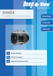
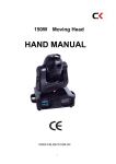
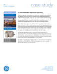
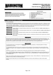
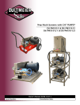
TM
CAVIDYNE , LLC
5077 Fruitville Road
Suite 109 - 157
Sarasota,FL 34234 USA
Phone: (352) 275-5319
www.caviblaster.com
Model 1222-E
CAVIDYNETM LLC is not responsible for damages or
injuries resulting from a failure to comply with instructions
in this manual. Please read entire manual carefully before
use.
The CaviBlaster® 1222-E must only be operated and
maintained by trained personnel.
This equipment generates high pressure water and is
intended for underwater use only. Serious personal
injury or death may result from improper use.
CaviBlaster® 1222-E Specifications
Nominal Pump Flow
12 GPM (45 LPM)
Operating Pressure
2,200-PSI (152 BAR)
Motor
20 HP (15 kW) 60 Hz (Baldor M4106T)
21 HP (16 kW) 50 Hz (Baldor M4107T – Rerate #4)
Installation Environment
Outdoor enclosed or exposed
Electrical Requirements
3-phase, 208-230/460 volts (60 Hz)
3-phase, 208-415 volts (50 Hz)
Water Inlet Pressure Limits
0-PSI (Atmospheric Pressure) to 125-PSI Maximum
(0 BAR to 8.6 BAR)
Overall Unit Dimensions (L x W x H)
45” x 32” x 30” (115 cm x 81 cm x 76 cm)
Maximum Pressure Hose Length
600 LF (200 meters) of ½” diameter thermoplastic hose
Power Unit Weight (Dry)
375 LBS (170 KG) 60 Hz
485 LBS (220 KG) 50 Hz
Zero-Thrust Lance Weight
6 LBS (3 KG)
2
1222-E OPERATING INSTRUCTIONS
WARNING: To ensure operator safety and efficient operation of the
CaviBlaster®, it is essential to follow these instructions.
Preparing the CaviBlaster® system for operation:
1. Inspect the CaviBlaster® power unit, hoses and lance for any signs of damage.
2. Check that the motor is clean and ventilation openings are clear.
3. Inspect inlet strainer (Figure 1) to ensure that it is not clogged. Clean if necessary.
4. Check for proper oil level in pressure pump (Figure 2).
5. Fill lubricating oil to proper level in the pressure pump (yellow cap on pump) (Figure 3) per
manufacturer’s operating manual. Use SAE 30 non-detergent lubricating oil.
Figure 1
Figure 2
Figure 3
6. To supply water to the CaviBlaster® power unit, connect a 1″ (25 mm) diameter feed hose to
the cam-lock plug on the inline strainer inlet (Figure 4). Either fresh water or seawater can be
used with this system. The water source must supply the CaviBlaster® with water at a volume
of greater than 12 gallons (45 liters) per minute at a maximum pressure of 70-psi (5 bar).
Ensure that the feed hose is connected to the pressure pump and the water is on prior to
starting the pressure pump.
7. Connect the 1″ (25 mm) red rubber bypass hose to the cam-lock plug on the pressureregulating unloader (Figure 5). The bypass hose has a cam-lock socket on one end. Direct the
bypass hose away from the working area and secure the hose.
3
Figure 4
Figure 5
Starting the CaviBlaster® power unit:
1. Turn on the water supply to the system.
2. Ensure that the system is primed with water
and that there are no leaks in the system. The
pressure pump is a positive displacement pump
and water must be supplied under pressure.
Failure to pump feed water to the pressure
pump will result in damage to the pump.
3. Once the system is primed, turn off the water
supply to the system.
4. Connect the ½″ (13 mm) high-pressure hose to
the quick-connect plug under the pressureregulating unloader ( Figure 6). The high pressure hose has a brass quick-connect socket
on the end. The 1222-E CaviBlasterTM can
deliver the required pressure utilizing up to 300
feet (100 meters) of ½″ diameter rubber hose or
600 feet (200 meters) of thermoplastic hose.
Using greater lengths or smaller diameters of
hose may degrade performance. If longer hose
lengths are required, ¾” (19 mm) diameter
hose must be used.
Figure 6
5. Connect the lance to the high pressure hose
(Figure 7) and submerge the lance in water.
6. Restart the water supply.
Figure 7
4
7. Connect the power cable for the motor to the
power source.
8. It is recommended that the lance trigger be in the
open or “ON” position (Figure 9) when starting the
motor.
9. Depress the green “START” button on the motor
controller (Figure 8) mounted on top of the motor
to start the motor.
10. The system is now ready to operate (refer to photo
on cover for overall system set-up).
Figure 8
Figure 8
Figure 9
WARNING: Although the CaviBlaster® system is safe to use when
submerged in water, the system generates a highpressure (up to 2,200-psi [150 bar]) water stream,
which can cause injury when the lance is out of the
water. ALWAYS keep the lance submerged when the
pressure pump is engaged.
5
Operating the CaviBlaster® system:
1. When the diver is ready to commence cleaning operations, ensure that the lance is submerged
in water. If the diver is not wearing a helmet, hearing protection is recommended. Cavidyne
recommends “Doc’s Proplugs” vented earplugs, or equivalent, for diver hearing protection.
2. Activate the cleaning cavitation stream by squeezing the trigger to the open or “ON” position
(Figure 9).
3. The most efficient operating technique is to hold the lance 2-3 inches (5-8 cm) away from the
surface to be cleaned and at a 25 to 45 degree angle to the surface being cleaned (Figure 9).
Placing the lance closer than 2-3 inches (5-8 cm) from the surface being cleaned will not
allow for efficient cavitation performance and will degrade the cleaning capability of the
system.
4. Wear neoprene or rubber gloves to protect the hands and follow all safety regulations that
may be applicable to the work being performed.
5. If the diver operating the unit must be replaced or the cleaning operation must be interrupted
for a prolonged period or terminated, shut down the motor by depressing the red “STOP”
button (Figure 8) on the motor controller. Turn off the water supply to the pump, and then
release the water pressure in the hose(s) by squeezing the lance trigger to the open or “ON”
position (Figure 9) while under water. Revert back to step 1 of the operating instructions
when the replacement diver is ready to continue cleaning.
6. Ensure that the lance is submerged any time the motor and pressure pump are operating.
Adjusting the CaviBlaster® system for maximum performance:
1. If using a calibration pressure gauge situated between the pressure hose and the CaviBlaster®
lance, the water pressure should be 2,200-psi (152 bar) with the lance submerged and the
lance trigger in the open or “ON” position. The pressure is adjusted by turning the nuts on the
end of the pressure-regulating unloader to compress or relax the green spring (Figure 10).
This adjustment increases or decreases the flow of water through the bypass hose when the
CaviBlaster® lance trigger is in the open or “on” position. The flow of water through the
bypass hose, in turn, determines the flow of water through the pressure hose and the lance.
Less flow through the bypass hose means more flow through the lance which translates to
higher velocity and pressure. Turn the nuts to compress the spring to decrease the amount of
water passing through the bypass and increase the water flow and pressure at the lance. Turn
the nuts to relax the spring to increase the amount of water passing through the bypass and
decrease the water flow and pressure at the lance. There should always be a trickle of water
through the bypass when the lance trigger is in the open or “ON” position. This ensures that
the bypass will open without a pressure shock wave damaging the pump when the lance
trigger is released to the closed position.
6
2. If using a pressure gauge located on the CaviBlaster® power
unit, the water pressure will need to be higher to account for
sidewall friction loss in the pressure hose. The pressure at the
pump should be 2,200-psi (152 bar) plus 0.75-psi per foot (0.17
bar per meter) of thermoplastic pressure hose. For example, if
using the CaviBlaster® with 100 feet (30 meters) of pressure
hose, the pressure gauge located next to the pump should
indicate 2,275-psi (157 bar). Pressure adjustments are made in
the same manner as described in paragraph 1 above. There
should always be a trickle of water through the bypass when
the lance trigger is in the open or “ON” position.
Figure 10
®
3. If adjusting the CaviBlaster without a pressure gauge, close
the pressure-regulating unloader until there is just a trickle of
water (less than ¼ gallon [1 liter] per minute) coming out of the
bypass with the lance trigger in the open or “ON” position.
Shutting down the CaviBlaster® power unit:
1. Stop the motor by depressing the red “STOP” button (Figure 8) on the motor controller.
2. Shut off the supply of water to the pump.
3. Squeeze the lance trigger to the open or “ON” position (Figure 9) to release the water
pressure remaining in the hose(s) while the lance is submerged.
4. It is now safe to remove the lance from the water.
5. Flush the system and rinse the power unit with fresh water at the end of the day.
Maintenance of the CaviBlaster® unit:
1. Empty and clean the inline strainer every day.
2. Check the pressure pump oil level and consistency every day.
3. Flush the system and rinse the power unit with fresh water after each days use.
4. Inspect the pump drive belt every week and replace the belt when cracking appears.
5. Change the oil in the pressure pump after the first 50 hours and every 500 hours thereafter.
(Use SAE 30 non-detergent lubricating oil.)
6. Check integrity of motor winding insulation with a “Megger” every 500 hours or 3 months.
7. Lubricate motor bearings with high grade ball or roller bearing grease every 3,600 hours.
8. Change the spring for the lance trigger every 12 months or less if required.
7
1.6 Inspection / Maintenance of the Zero-Thrust Gun
In order to minimize potential problems with the Zero-Thrust Gun it is recommended that
the gun be treated at the end of each work period:
1. Flush and rinse the gun with fresh water after each use in sea water.
2. Place the gun in a container of clean, fresh water if it will be used in the next 24
hours. Ensure the gun is completely submerged.
3. If the gun will not be used for a period of several days, remove the super swivel from
the gun handle and, with the gun turned upside-down, pour approx. 5ml of lubricating
oil into the water inlet while opening and closing the trigger. This will allow oil to
reach the positioning pin and valve cone and minimize the possibility of corrosion or
mineral crystals forming that would freeze the pin or valve cone.
4. Do not use WD-40 for long term storage.
Valve Cartridge Assembly
Positioning Pin
Trigger
Water Inlet with Super
Swivel.
Figure 11 – Zero-Thrust Gun
8
Summarizing the operating instructions:
1. Inspect the system for damage.
2. Check and clean the inlet strainer.
3. Check pressure pump oil level.
4. Attach the feed and bypass hoses.
5. Start the water supply and ensure that the system is primed (water should be
coming out of the pressure hose quick-connect plug [Figure 6]).
6. Attach the pressure hose and lance.
7. Connect the power cable to the power source.
8. Make sure that the diver is ready to work and that the lance is submerged in the
water. Hearing protection is recommended if the diver is not wearing a helmet.
9. Start the motor.
10. Activate the cleaning cavitation stream by squeezing the lance trigger to open
or “ON.”
11. Proceed with cleaning.
12. Stop the motor.
13. Shut off the water supply to the pump.
14. Release pressure from the hose(s) by squeezing the lance trigger to the open or
“ON” position while under water.
15. Remove the lance from the water.
16. Disconnect the power cable from the power source.
17. Flush the system and rinse the outside of the power unit with fresh water.
18. Disconnect the feed, bypass and pressure hoses.
9
WARNING
While the CaviBlaster® system is very safe, operators should exercise care when using
the equipment. The cavitation “flame” can be safely passed over the operators’ skin at
normal operating distances of 2” - 3” (5 - 8 cm) from the tip of the nozzle. However, at
very close distances (typically less than 1” [2.5 cm]) both nozzles are capable of causing
harm to the operator, particularly in the initial instant that the system is activated. For that
reason, operators should exercise caution when operating the lance with the nozzles
in close proximity to the body. The operators should also ensure that the reversethrust nozzle guard is secured in the correct position prior to operating the lance.
The operators of the CaviBlaster® system should always wear neoprene or heavy
rubber gloves to provide protection to the hands and, in particular, to the nails. The
gloves will absorb most of the energy produced by bursting cavitation bubbles and
prevent the cavitation bubbles from contacting the operators’ hands. The gloves will also
protect operators’ hands from the initial shockwave when the lance is activated.
Serious harm and injury may result from the misuse of CaviBlaster® system
equipment or improperly selected fittings, hoses or attachments. All components of
the system should be checked against the manufacturers’ instructions to ensure that they
are compatible with the pressures being used and of the correct thread type and pressure
rating for the intended service. Refer to these Operating Instructions and to the motor and
pressure pump manufacturers’ operation manuals for instructions or call CaviDyne™,
LLC at (352) 275-5319 with any questions.
10
APPENDIX - COMPONENT LITERATURE
Baldor Electric
Model M4106T
Motor Spec Sheet
Motor Information
Motor Operation Manual
Baldor Electric
Model M4107T
Motor Spec Sheet
Motor Information
General Pump
Model TSF 2421
CAT Pumps
Pulsation Dampener
Model 6029
General Pump
Pressure Regulating
Unloader Model YU2140
Suttner
Trigger Gun
Model ST-2700
Warranties
Pump Spec Sheet
Pump Service Manual
Crankcase Oil Data Sheet and MSDS
Spec Sheet
Valve Spec Sheet
Gun Schematic Drawing
CaviDyne™
Baldor Electric
General Pump
CAT Pumps
Suttner
11