1
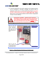
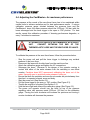
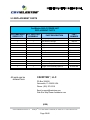
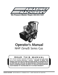
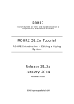
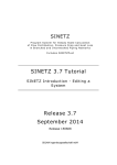
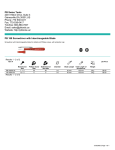
TM CAVIDYNE , LLC P.O. Box 358628 Gainesville, FL 32635 Phone: (352) 275-5319 Web Site: www.caviblaster.com Model 2022-C CaviDyne,TM LLC is not responsible for damages or injuries resulting from a failure to comply with instructions in this manual. Please read entire manual carefully before use. The CaviBlasterTM 2022 must only be operated and maintained by trained personnel. This equipment generates high pressure water and is intended for underwater use only. Serious personal injury or death may result from improper use. Commercial Diver’s gear should be used to operate the CaviBlasterTM system. © 2010 O&M Manual Version 1.2 CaviDyneTM P.O. Box 358628 Gainesville, FL 32635 U.S.A. Phone 352.275 5319 Page 2/40 TABLE OF CONTENTS 1.0 UNIT SPECIFICATIONS ........................................................................................... 5 2.0 GENERAL DESCRIPTION ........................................................................................ 6 2.1 Using this Manual .................................................................................................. 8 2.2 Conventions ........................................................................................................... 9 2.3 Scope .................................................................................................................... 9 2.4 Terms and Abbreviations ....................................................................................... 9 3.0 SAFETY INFORMATION ........................................................................................ 10 3.1 Personal Safety ................................................................................................... 10 3.2 Personal Protective Equipment............................................................................ 11 3.3 Modification to the Equipment.............................................................................. 12 4.0 INSTALLATION....................................................................................................... 13 4.1 Uncrating and Lifting ............................................................................................ 13 4.2 Installation Location ............................................................................................. 14 4.3 Initial Set-Up ........................................................................................................ 15 4.3.1 Connecting the Battery Terminals ................................................................. 15 4.3.2 Connecting the Water Source ....................................................................... 16 5.0 OPERATION ........................................................................................................... 20 5.1 Preparing the CaviBlasterTM for Operation ........................................................... 20 5.2 Startup of the CaviBlasterTM ................................................................................. 21 5.3 Normal Operation ................................................................................................ 22 5.4. Adjusting the CaviBlasterTM for Maximum Performance ...................................... 24 5.5. Recommendations for Effective Results ............................................................. 27 5.6. Shutting Down the CaviBlasterTM ........................................................................ 27 6.0 MAINTENANCE ...................................................................................................... 30 6.1 Preventive Maintenance Recommendations ....................................................... 31 6.2 Diesel Engine Service .......................................................................................... 32 6.3 Pump Service ...................................................................................................... 32 6.4 Inspection/Cleaning of Water Inlet Strainer ......................................................... 32 6.5 Inspection / Maintenance of the Belt Drive System.............................................. 34 7.0 WINTERIZATION .................................................................................................... 37 8.0 TROUBLESHOOTING ............................................................................................ 37 9.0 REPLACEMENT PARTS ........................................................................................ 39 APPENDIX - COMPONENT LITERATURE .................................................................. 40 © 2010 O&M Manual Version 1.2 CaviDyneTM P.O. Box 358628 Gainesville, FL 32635 U.S.A. Phone 352.275 5319 Page 3/40 LIST OF FIGURES & TABLES Figure 1.1 – CaviBlasterTM 2022-C Specifications ........................................................... 5 Figure 2.1 – CaviBlasterTM 2022 General Features ......................................................... 7 Figure 2.2 – CaviBlasterTM 2022 Control Panel ............................................................... 8 Figure 4.1 – Lifting Guidelines ....................................................................................... 13 Figure 4.2 – Installation Guidelines ............................................................................... 14 Figure 4.3 – Reconnecting the Battery Terminals ......................................................... 16 Figure 4.4 – Gravity Feeding Source............................................................................. 17 Figure 5.1 – Engine Emergency Shut-Down and Throttle Control ................................. 23 Figure 5.2 – Lance Pressure Calibration ....................................................................... 23 Figure 5.3 – Lance Position for Best Results ................................................................ 23 Figure 6.1 – Inspection / Cleaning Water Filter ............................................................. 33 Figure 6.2 – Inspection / Belt tension ............................................................................ 35 This space intentionally left blank © 2010 O&M Manual Version 1.2 CaviDyneTM P.O. Box 358628 Gainesville, FL 32635 U.S.A. Phone 352.275 5319 Page 4/40 1.0 UNIT SPECIFICATIONS The CaviBlasterTM 2022-C power unit consists of a 34HP Kohler KDW 1404 diesel power-pack and a CAT 2510 triplex plunger pump. Detailed performance and specifications are listed below: CaviBlasterTM 2022-C Specifications Nominal Pump Flow 20 GPM (75.6 LPM) Operating Pressure 2200-PSI (152 BAR) Engine 34 HP, Diesel Powered (Kohler KDW 1404) Installation Environment Outdoor enclosed or exposed Fuel Requirements Diesel fuel (ASTM Grade No. 1-D or 2-D) Fuel Tank Capacity 6.5 Gallons (24.5 Liters) Water Inlet Pressure Limits 0-PSI (Atmospheric Pressure) to 70-PSI Maximum (0 BAR to 4.8 BAR) See Section 4 for further requirements Overall Unit Dimensions (L x W x H) 47” x 38” x 37” (119 cm x 97 cm x 94 cm) Maximum Pressure Hose Length 600 LF (200 meters) of 3/4” diameter thermoplastic Power Unit Weight (Dry) 820 LBS (370 KG) Zero-Thrust Lance Weight 13 LBS (5.9 KG) See Section 4 for installation requirements Figure 1.1 – CaviBlasterTM 2022-C Specifications This space intentionally left blank (EOS) © 2010 O&M Manual Version 1.2 CaviDyneTM P.O. Box 358628 Gainesville, FL 32635 U.S.A. Phone 352.275 5319 Page 5/40 2.0 GENERAL DESCRIPTION The CaviBlasterTM 2022 high-pressure water power unit allows the operator to use the water flow and pressure to generate cavitation at the end of the proprietary nozzle. The CaviBlasterTM cleans the surface of any underwater structure using the energy released by the implosion of the bubbles during the cavitation process. When directed at the surface being cleaned, the energy released by the collapsing bubbles causes marine growth to be removed from the surface. The system consists of a portable, zero-thrust lance, connecting high-pressure hose and a diesel-powered, high-pressure pumping unit. The zero-thrust lance uses a triggeroperated valve to control the water stream off and on. If the valve is closed, the power unit goes into bypass mode unloading the engine and the pump. FULL LOAD is defined as the engine at full throttle / full speed. If partially throttled, the engine will stall, creating an undesirable running condition for the centrifugal clutch. The CaviBlasterTM 2022 power unit is a complete “plug and play” system built into a selfsupporting frame that allows quick deployment and/or installation of the unit. Water can be supplied from either a pressurized source, directly from the natural source via an electric booster pump supplied with the power unit, or from a gravity storage feed tank. The unit is equipped with many features to maintain operator safety while operating at pressures of 2,200-psi (152 bar). © 2010 O&M Manual Version 1.2 CaviDyneTM P.O. Box 358628 Gainesville, FL 32635 U.S.A. Phone 352.275 5319 Page 6/40 For more information on the CaviBlasterTM system please visit us at: www.caviblaster.com Fuel cap Lifting eyes Fuel tank Pulsation dampener Fuel level gauge Relief valve Control panel – see Figure 2.2 Pressure pump Pressure regulator Suction filter Forklift slots Figure 2.1 – CaviBlasterTM 2022 General Features © 2010 O&M Manual Version 1.2 CaviDyneTM P.O. Box 358628 Gainesville, FL 32635 U.S.A. Phone 352.275 5319 Page 7/40 Feed pump electrical connection Engine ignition / control panel Emergency engine shut down Feed pump switch (pull on / push off) Throttle cable control (push red button to release / twist black knob to lock) Feed or suction hose – 1-¼” cam-lock By-pass hose - 1” cam-lock Pressure hose – ¾” JIC Figure 2.2 – CaviBlasterTM 2022 Control Panel 2.1 Using this Manual (Version 1.2) Every attempt has been made to ensure that this documentation is complete and accurate at the time of publication. It is imperative; however, that anyone attempting to use this manual must have good comprehension of how this equipment operates. Further, this manual can in no way replace the common sense of an individual. If at any time this manual seems to contradict itself, or common sense, discontinue the procedure, re-read the section, and seek assistance from CaviDyneTM or other personnel familiar with the operation of this equipment. © 2010 O&M Manual Version 1.2 CaviDyneTM P.O. Box 358628 Gainesville, FL 32635 U.S.A. Phone 352.275 5319 Page 8/40 2.2 Conventions The first time a component is mentioned, it is typically followed by a figure reference; e.g., Emergency Stop button (See Figure 2.1). Figure numbers and section numbers are always coincident. When other sections are referenced the SECTION NAME will appear in italic caps. The electronic version allows users to click on the section name or figure reference to jump to that section. The words “This space intentionally left blank” will appear where there is more than 3 inches of white space. (EOS) will appear above the page number on the last page of each section. 2.3 Scope This manual covers installation, operation, and maintenance of the CaviBlaster TM 2022. It is essential that personnel who will operate and/or service this equipment familiarize themselves with this manual. Standard components, such as the unit engine and pump, are covered by the manufacturer’s literature found in the Appendix. 2.4 Terms and Abbreviations CCW CW EOS GPM HP LPM PPE PSI Counterclockwise Clockwise End of Section Gallons Per Minute Horsepower Liters Per Minute Personal Protective Equipment Pounds Per Square Inch (without suffix, assumed to be gauge pressure). (EOS) © 2010 O&M Manual Version 1.2 CaviDyneTM P.O. Box 358628 Gainesville, FL 32635 U.S.A. Phone 352.275 5319 Page 9/40 3.0 SAFETY INFORMATION The CaviBlasterTM 2022 power unit is an inherently powerful and potentially dangerous piece of equipment; however, with proper care and training it can be operated safely. The 2022 must only be operated by personnel that have read and understand this manual. It is intended to reinforce and review safety techniques to prevent personal injuries and property damage. Users must comply with all local, state, and national laws concerning high-pressure water jetting equipment as well as all underwater work regulations. It is strongly recommended that this entire manual be reviewed in-depth before operating or servicing this equipment. Service work should only be performed by individuals who are proficient in using this equipment. Refer to the applicable section in this manual for the correct procedures prior to any installation, setup, or maintenance work. 3.1 Personal Safety Operation of the CaviBlasterTM 2022 underwater cleaning system must only be attempted by commercial divers or other personnel who have been trained in its use. Appropriate protective equipment should always be worn. Operation of the system without the proper equipment and training can result in personal injury. CaviDyneTM, LLC is not responsible for damages resulting from a failure to comply with instructions in this manual. Please read carefully before use. If maintenance or repair of the CaviBlasterTM lance is being conducted out of the water, remember that the zero-thrust lance has front and rear jets. Never direct the jet streams at a person or animal. Never direct the jet streams toward power lines or other high voltage equipment. © 2010 O&M Manual Version 1.2 CaviDyneTM P.O. Box 358628 Gainesville, FL 32635 U.S.A. Phone 352.275 5319 Page 10/40 Ensure that there is a safe area to work while operating the CaviBlasterTM 2022. Seek immediate medical attention if the operator suffers an injury as the result of contact with the high-pressure water stream. Serious personal injury can result from an untreated water injection wound. 3.2 Personal Protective Equipment Always wear appropriate Personal Protective Equipment (PPE) when operating this equipment. Personnel operating or working in the vicinity of the power unit should wear appropriate hearing protection when the CaviBlasterTM system is in use. If the diver is not wearing a diving helmet, hearing protection is recommended. CaviDyneTM suggest wearing vented earplugs, such as “Doc’s Proplugs”, for diver hearing protection. The operators of the CaviBlasterTM system should always wear neoprene or heavy rubber gloves to provide protection to the hands and, in particular, to the nails. The gloves will absorb most of the energy produced by bursting cavitation bubbles and prevent the cavitation bubbles from contacting the operators’ hands. The gloves will also protect operators’ hands from the initial shockwave when the lance is activated. Failure to wear appropriate PPE may result in personal injury. © 2010 O&M Manual Version 1.2 CaviDyneTM P.O. Box 358628 Gainesville, FL 32635 U.S.A. Phone 352.275 5319 Page 11/40 3.3 Modification to the Equipment Do not make any unauthorized modifications or repairs to this equipment. Components used throughout this assembly were specifically designed or selected to safely meet the unique high-pressure requirements. Only replace parts with those recommended by or supplied by CaviDyneTM. Any unapproved modifications will void the equipment warranty. Unauthorized modification or part substitution can result in serious personal injury or property damage. Unauthorized replacement of any part may lead to catastrophic equipment failure and serious personal injury. This space intentionally left blank (EOS) © 2010 O&M Manual Version 1.2 CaviDyneTM P.O. Box 358628 Gainesville, FL 32635 U.S.A. Phone 352.275 5319 Page 12/40 4.0 INSTALLATION The CaviBlasterTM 2022 must be installed in accordance with the requirements outlined below. The unit can be installed in a vehicle to allow for maximum mobility and flexibility. 4.1 Uncrating and Lifting Unpack the equipment and inspect for damage. If damage is found, immediately contact CaviDyneTM and the shipping company. If the unit will not be installed immediately, provide adequate indoor storage to protect against damage. The CaviBlasterTM power unit should be lifted from underneath the frame using the forklift channels or by using the lifting eyes provided on top of the frame. Verify that lifting equipment is rated for the weight listed in Section 1.0 UNIT SPECIFICATIONS and that the unit is stable before lifting. Lift unit using lifting eyes Lift Unit from Underneath Frame Figure 4.1 – Lifting Guidelines © 2010 O&M Manual Version 1.2 CaviDyneTM P.O. Box 358628 Gainesville, FL 32635 U.S.A. Phone 352.275 5319 Page 13/40 4.2 Installation Location For maximum flexibility the CaviBlasterTM power unit should be installed in an area where it is capable of reaching both its water source and anticipated cleaning targets within acceptable hose lengths. The CaviBlasterTM power unit can be installed in an enclosed* or open environment. * Enclosed installations will require provisions for adequate engine cooling air flow and for venting of engine exhaust. See Figure 4.2 below. Installation location must be a level surface able to safely support the unit weight listed in Section 1.0 UNIT SPECIFICATIONS. Orient unit to allow unrestricted access to the hose connection plate and control panel, located on the front of the unit. Allow a minimum of three feet behind the unit and access from above to conduct service and repair work. Take note of frequently serviced areas such as the engine and fuel tank. Fuel tank filling port Engine exhaust lower part Allow access to service belts Engine air flow Allow access to front control panel Allow access for general service Figure 4.2 – Installation Guidelines © 2010 O&M Manual Version 1.2 CaviDyneTM P.O. Box 358628 Gainesville, FL 32635 U.S.A. Phone 352.275 5319 Page 14/40 4.3 Initial Set Up After first receiving the CaviBlasterTM power unit, the following must be checked and completed: 1) Connect the battery (See Section 4.3.1). 2) Add engine oil (See Engine Manual located in the APPENDIX). 3) Add engine coolant (See Engine Manual located in the APPENDIX). 4) Add pump oil (See Pump Manual located in the APPENDIX). 5) Connect the feed or suction hose (See Section 4.3.2). 6) Connect the bypass hose (See Figure 2.2). 7) Connect the pressure hose (See Figure 2.2). 8) Connect the electric feed pump (See Section 4.3.2). 9) Fill the fuel tank (See fuel requirements in Engine Manual located in the APPENDIX). Engine and/or pump fluids may have been removed for shipment. Check fluid levels prior to starting. 4.3.1 Connecting the Battery Terminals For shipping purposes, the battery terminals have been disconnected. To reconnect the battery, reference Figure 4.3 and the procedure below: 1. Push IN the Emergency Stop button located on the front control panel (See Figure 2.2). 2. Open the battery box by loosening the strap and removing the cover. 3. Connect the battery terminals as follows: RED to positive terminal BLACK to negative terminal 4. Tighten the terminal screws securely. 5. Replace the battery cover and secure with strap. © 2010 O&M Manual Version 1.2 CaviDyneTM P.O. Box 358628 Gainesville, FL 32635 U.S.A. Phone 352.275 5319 Page 15/40 1. Remove Strap Positive (Red) 2. Lift-Off Cover Negative (Black) Main Battery Location 3. Connect Terminals Figure 4.3 – Reconnecting the Battery Terminals 4.3.2 Connecting the Water Source The CaviBlasterTM power unit can be used with seawater or fresh water. It must be flushed with fresh water for 1-2 minutes after each use in seawater to ensure long service life. The CaviBlasterTM 2022 must be flushed and rinsed with fresh water after every use in seawater. © 2010 O&M Manual Version 1.2 CaviDyneTM P.O. Box 358628 Gainesville, FL 32635 U.S.A. Phone 352.275 5319 Page 16/40 Failure to flush and rinse the power unit after use in seawater will result in increased wear and tear on components and in decreased service life. Failure to flush and rinse the unit can cause the pump valve(s) to stick in the open position. This will prevent the system from producing the correct operating pressure. The feed water inlet connection is located on the control panel (See Figure 2.2). An electric submersible water pump is supplied to provide positive inlet water pressure to the main pressure pump. Two water supply conditions are acceptable for the CaviBlasterTM power unit. Forced inlet water condition using the supplied electric water pump or an outside water source capable of supplying at least 25 GPM (95 LPM) at a maximum pressure of 70-PSI (4.8 BAR). Gravity feeding water source (See Figure 4.4). In this case the electric pump is not required. Use a hose with a diameter of at least 1-1/4” to connect the water tank to the power unit. Pump inlet must be below the tank bottom Water level Figure 4.4 – Gravity Feeding Source © 2010 O&M Manual Version 1.2 CaviDyneTM P.O. Box 358628 Gainesville, FL 32635 U.S.A. Phone 352.275 5319 Page 17/40 To use the feed pump supplied with the system: Turn the engine ignition key to OFF (See Figure 2.2). Push IN the Emergency Engine Shut-Down button to ensure that power to the engine has been disconnected. (See Figure 2.2). Connect the cam-lock socket on the 1-1/4” clear PVC feed hose to the water inlet connection on the control panel (See Figure 2.2). Connect the electrical plug on the feed pump power cable to the matching receptacle on the control panel (See Figure 2.2). Submerse the feed pump into the water source. Release the Emergency Engine Shut-Down button. Pull the feed pump ON/OFF switch out to activate the feed pump (See Figure 2.2). It is important not to operate the feed pump for long periods of time without the engine operating as this will discharge the battery. To use force feed from an alternate source: Turn the engine ignition key to OFF (See Figure 2.2). Push IN the Emergency Engine Shut-Down button to ensure that power to the engine has been disconnected. (See Figure 2.2). When feeding the CaviBlasterTM with an alternate water source, the source must supply water at a volume of greater than 20 gallons (75 liters) per minute at a maximum of 70-psi (4.8 bar). Connect a 1-1/4” cam-lock socket on the water supply hose to the water inlet connection on the control panel (See Figure 2.2). Turn on the alternate water source. Release the Emergency Engine Shut-Down button. Ensure that the feed hose is connected to the inlet connection and the water supply is on prior to starting the pressure pump. Failure to supply to the pressure pump will cause damage to the pump. © 2010 O&M Manual Version 1.2 CaviDyneTM P.O. Box 358628 Gainesville, FL 32635 U.S.A. Phone 352.275 5319 Page 18/40 To use gravity feed: Locate the water supply tank so that the bottom of the tank is higher than the water inlet on the control panel (See Figures 2.2 and 4.4). Turn the engine ignition key to OFF (See Figure 2.2). Push IN the Emergency Engine Shut-Down button to ensure power has been disconnected. (See Figure 2.2). Connect a minimum 1-1/4” hose to the water inlet 1-1/4” cam-lock plug. Connect the other end of the hose to the water supply tank. Make sure the lowest point in the hose line is the connection with the power unit. Release the Emergency Engine Shut-Down button. It is essential that adequate water is supplied to the water supply tank to maintain the water level several inches above the bottom of the tank. Failure to maintain an adequate water level in the supply tank could starve the pressure pump of water causing damage to the seals or other components of the pressure pump. Ensure that the water source can reliably deliver the maximum pump flow of 20 GPM (75 LPM). A minimum flow of 25 GPM (95 LPM) is recommended to ensure that the pump is not starved of water. If connecting to a tank, locate the bottom of the tank above the water inlet connection on the power unit to ensure a flooded suction line (See Figure 4.4). This space intentionally left blank (EOS) © 2010 O&M Manual Version 1.2 CaviDyneTM P.O. Box 358628 Gainesville, FL 32635 U.S.A. Phone 352.275 5319 Page 19/40 5.0 OPERATION The CaviBlasterTM 2022 should be operated by two (2) properly trained individuals. One, the diver, operates the zero-thrust lance, while the other operates the power unit. Both operators should be in audio or visual communication with each other. The CaviBlasterTM 2022 should only be operated by properly trained personnel who are familiar with the contents of the manual. Review the safety requirements found in Section 3 before operating. 5.1 Preparing the CaviBlasterTM for Operation The following checklist should be completed in advance, so that the unit is always ready for immediate use. This should be completed after each use. 1) Inspect the CaviBlasterTM power unit, hoses, JIC fittings and lance for any signs of damage 2) Inspect the inline strainer to ensure that it is not clogged (See Figure 6.1). 3) Check for proper engine oil level (See engine Owner’s Manual found in the Appendix). Add lubricating oil (SAE 10W40) if necessary. 4) Check for proper pressure pump oil level (See pump Owner’s Manual found in the Appendix). Add hydraulic oil (SAE 30 non-detergent) if necessary. 5) Check fuel tank (See Figure 2.1) for proper diesel fuel level. Add diesel fuel (ASTM Grade No. 1-D or 2-D, or EN 590) if necessary. Incorrect fuels should not be used as they may prove hazardous. © 2010 O&M Manual Version 1.2 CaviDyneTM P.O. Box 358628 Gainesville, FL 32635 U.S.A. Phone 352.275 5319 Page 20/40 5.2 Startup of the CaviBlasterTM Before starting the CaviBlasterTM 2022 power unit, review all safety requirements found in Section 3.0 SAFETY INFORMATION. This equipment should only be operated by individuals who have read and understand the CaviBlaster TM Operation and Maintenance Manual. 1) Verify that the unit has been properly prepared for operation as described in Section 4. 2) Verify that the lance is properly connected and the mechanical trigger is released. 3) Verify that the Emergency Engine Shit-Down knob (See Figure 2.2) is released by twisting and pulling it out. 4) Verify that the throttle cable is fully depressed (See Figure 5.1). 5) Apply appropriate hearing protection prior to starting engine. 6) Insert the key into the ignition switch on the ignition panel (See Figure 2.2). Turn the key clockwise one position to heat the glow plugs. Once the plug preheat light (the top right light on the panel) turns off, turn the key farther clockwise to start the engine. If the engine does not start within 10 seconds, return the key to the “OFF” position and wait at least 30 seconds before operating the starter again. Once the engine starts, release the key, allowing it to return to the “ON” or running position. 7) Run the engine at idle speed for a minimum of 20 seconds (20”) at ◦ ◦ operating temperatures above 41 F (5 C). For lower operating temperatures, run engine at idle speed for a minimum of one minute (1’). DO NOT THROTTLE UP THE ENGINE UNTIL THE DIVER IS READY FOR UNDERWATER OPERATION. The engine must be run at full throttle / full speed. If partially throttled, the engine will stall, creating an undesirable running condition for the centrifugal clutch. © 2010 O&M Manual Version 1.2 CaviDyneTM P.O. Box 358628 Gainesville, FL 32635 U.S.A. Phone 352.275 5319 Page 21/40 5.3 Normal Operation Normal operation of the CaviBlasterTM system is defined as user control of water flow via the lance trigger. Control of the power unit from the lance trigger is accomplished by a mechanical shut-off valve in the lance. Should a problem develop with the control valve, discontinue using the CaviBlasterTM until fixed. The CaviBlasterTM 2022 power unit is designed to operate in two modes: idle and full throttle. Less than full throttle will result in malfunction of the belt drive system and the performance of the centrifugal clutch. Review the safety requirements for PPE and safe operation before proceeding. 1) Startup the power unit as described in Section 5.2. 2) Connect the lance to the high-pressure hose and unroll sufficient length of hose to reach the operating location. 3) When the diver is ready to commence cleaning operations, ensure that the lance is submerged in water. Ensure that the power unit operator and other persons working in the vicinity of the power unit wear appropriate hearing protection when the engine is running. If the diver is not wearing a helmet, hearing protection is recommended. CaviDyne suggests vented earplugs such as “Doc’s Proplugs” for diver hearing protection. 4) Wear neoprene or rubber gloves to protect the hands and follow all safety regulations that may be applicable to the work being performed. 5) The lance trigger should be in open or “ON” position (See Figure 5.3) when throttling up the engine to engage the pressure pump. This will prevent the pressure pump from being in a loaded condition which will cause the clutch and belt to slip while they are engaging the pressure pump. 6) Throttle the engine up by completely pulling the black throttle cable knob all the way out and twisting the knob to lock it (See Figure 5.1). 7) Activate the cleaning cavitation stream by squeezing the trigger to the open or “ON” position (See Figure 5.3). Release trigger to stop the water flow and direct to bypass. © 2010 O&M Manual Version 1.2 CaviDyneTM P.O. Box 358628 Gainesville, FL 32635 U.S.A. Phone 352.275 5319 Page 22/40 8) If the diver operating the unit must be replaced or the cleaning operation must be interrupted or terminated, disengage the pressure pump by pushing the throttle lever in to the idle position (See Figure 5.1) and then release the water pressure in the hose(s) by squeezing the lance trigger to the open or “ON” position (See Figure 5.3) while under water. Revert back to step 3 of the operating instructions when the diver or replacement is ready to continue cleaning. Although the CaviBlasterTM system is safe to use when submerged in water, the system generates a high-pressure (up to 2,200-psi [152 bar]) water stream, which can cause injury when the lance is out of the water. ALWAYS keep the lance submerged when the pressure pump is engaged. Emergency engine shut-down knob Push on the red knob for emergency engine shut-down, twist and pull the red knob out to release engine shutdown. Push on the red knob to release, pull the cable all the way out and twist to lock. Throttle cable knob Figure 5.1 – Engine Emergency Shut-Down and Throttle Control © 2010 O&M Manual Version 1.2 CaviDyneTM P.O. Box 358628 Gainesville, FL 32635 U.S.A. Phone 352.275 5319 Page 23/40 5.4. Adjusting the CaviBlasterTM for maximum performance The pressure at the nozzle of the zero-thrust lance has to be maintained within certain limits to achieve cavitation and for best performance results. If using a calibration pressure gauge situated between the pressure hose and the CaviBlasterTM lance, the water pressure should be 2,200-psi (152 bar) with the lance submerged and the lance trigger in the open or “ON” position. For best results, repeat this calibration procedure if cleaning performance degrades, or every 3 months at a maximum. A CALIBRATION GAUGE IS RECOMMENDED WITH EVERY UNIT. CONNECT BETWEAN THE END OF THE THERMOPLASTIC HOSE AND THE WHIP HOSE OR LANCE. To calibrate the pressure at the zero-thrust lance, follow the procedure below: - - Stop the power unit and pull the lance trigger to discharge any residual pressure in the hose lines. Disconnect the lance with its whip hose from the main hose line. Attach the calibration gauge and tighten the JIC connections. Submerge the lance. Because of the danger of the operator coming in contact with either of the water streams from the cavitating or zero-thrust nozzles, Cavidyne does NOT recommend calibrating the lance out of the water. Use extra care to avoid both water streams if doing so. Ensure that both the cavitation and zero-thrust nozzles are pointed away from the diver’s or operator’s hands, arms and body. Start the power unit (See Section 5.2). Pull the lance trigger to the open or “ON” position (See Figure 5.3). Throttle the engine to full speed (See Section 5.3). Hold the lance tight and observe the calibration gauge (See Figure 5.2). The power unit operator should turn the knob on top of the pressure regulating valve until pressure reads 2,200-psi (152 bar) on the calibration gauge. Turning the knob clockwise will increase the pressure and turning it counter clockwise will decrease the pressure. © 2010 O&M Manual Version 1.2 CaviDyneTM P.O. Box 358628 Gainesville, FL 32635 U.S.A. Phone 352.275 5319 Page 24/40 To calibrate the pressure at the CaviBlasterTM power unit, the water pressure at the power unit will need to be higher to account for sidewall friction loss in the pressure hose. The pressure at the pump should be 2,200-psi (152 bar) plus 0.5-psi per foot (0.11 bar per meter) of thermoplastic pressure hose. For example, if using the CaviBlasterTM with 100 feet (30 meters) of pressure hose, the pressure gauge located next to the pump should indicate 2,250-psi (155 bar). Pressure adjustments are made by turning the knob on top of the pressure regulating valve in the same manner as described above. DO NOT ADJUST THE PRESSURE AT THE LANCE TO MORE THAN 2,200-PSI. HIGHER PRESSURE WILL NOT IMPROVE PEFORMANCE. PUMP AND HOSES ARE RATED FOR 2,500-PSI. PRESSURES ABOVE 2,500-PSI COULD RESULT IN PUMP AND/OR HOSE FAILURE. This space intentionally left blank © 2010 O&M Manual Version 1.2 CaviDyneTM P.O. Box 358628 Gainesville, FL 32635 U.S.A. Phone 352.275 5319 Page 25/40 Whip hose Main hose Calibration gauge Whip hose Figure 5.2 – Lance Pressure Calibration © 2010 O&M Manual Version 1.2 CaviDyneTM P.O. Box 358628 Gainesville, FL 32635 U.S.A. Phone 352.275 5319 Page 26/40 5.5. Recommendations for Effective Results Once the engine is throttled up to operating speed and the water trigger is pulled, the diver has to find the most effective distance between the lance nozzle and the surface being cleaned. When the diver is ready to commence cleaning operations, ensure that the lance trigger is in the open or “ON” position (Figure 5.3), the lance is submerged in the water and the feed pump is operating prior to throttling up the engine. Ensure that the power unit operator and other people working in the vicinity of the power unit wear appropriate hearing protection when the engine is running. 1. Engage the pressure pump by pulling the engine throttle lever (Figure 5.1) to the operating speed position (fully extended) to engage the centrifugal clutch. Tighten the thumb screw to hold throttle in operating speed position. 2. The most efficient operating technique is to hold the nozzle 2-5 inches (5-12 cm) away from the surface to be cleaned and at a 25 to 45 degree angle to the surface being cleaned (See Figure 5.3). The diver needs to observe the shape of the cavitating jet cone. At greater depths, the higher ambient pressure will cause the jet cone to be shorter. The widest zone of the cone is the most efficient part of the cavitating jet. Placing the nozzle closer than 2 inches (5 cm) from the surface being cleaned will not allow for efficient cavitation performance and will degrade the cleaning capability of the CaviBlasterTM system. 3. Follow all safety regulations that may be applicable to the work being performed. 4. If the diver operating the CaviBlasterTM unit must be replaced or the cleaning operation must be terminated, disengage the pressure pump by pushing the throttle lever in to the idle position (Figure 5.1) and release the water pressure remaining in the hose(s) by moving the lance trigger to the open or “ON” position while under water. Revert to step 1 of the operating instructions when the diver or replacement is ready to continue cleaning. © 2010 O&M Manual Version 1.2 CaviDyneTM P.O. Box 358628 Gainesville, FL 32635 U.S.A. Phone 352.275 5319 Page 27/40 Figure 5.3 – Lance Position for Best Results This space intentionally left blank © 2010 O&M Manual Version 1.2 CaviDyneTM P.O. Box 358628 Gainesville, FL 32635 U.S.A. Phone 352.275 5319 Page 28/40 5.6 Shutting Down the CaviBlasterTM 1. Adjust the engine speed to idle by pushing on the red throttle cable knob (See Figure 5.1). This will disengage the clutch and pressure pump. 2. Run the engine at idle speed for a few minutes. 3. Push the feed pump ON/OFF switch in to stop the pump (See Figure 2.2). If using force feed from an alternate source or if using gravity feed, shut off the supply of water to the pressure pump. 4. Shut off the engine by turning the key counter- or anti-clockwise or to the “OFF” position (See Figure 2.1). 5. Squeeze the lance trigger to the open or “ON” position (See Figure 5.3) to release the water pressure remaining in the hose(s) while the lance is submerged. 6. It is now safe to remove the lance from the water. 7. Flush the system and rinse the power unit with fresh water at the end of the day. This space intentionally left blank EOS © 2010 O&M Manual Version 1.2 CaviDyneTM P.O. Box 358628 Gainesville, FL 32635 U.S.A. Phone 352.275 5319 Page 29/40 6.0 MAINTENANCE Maintenance on this unit should be restricted to authorized personal that have been properly trained. Review this manual, especially Section 3.0 SAFETY INFORMATION, prior to performing any service on this equipment. Equipment must be OFF prior to performing any service work. Only replace parts with those supplied or approved by CaviDyneTM. Use of any other parts may lead to equipment failure and severe personal injury. CAVIBLASTERTM MUST BE FLUSHED AND RINSED WITH FRESH WATER AFTER EACH USE IN SEA WATER. FAILURE TO FLUSH AND RINSE THE UNIT WILL RESULT IN PREMATURE WEAR AND TEAR ON THE COMPONENTS AND DECREASED SERVICE LIFE. Failure to flush and rinse the unit can cause the pump valve(s) to stick in the open position. This will prevent the system from producing the correct operating pressure. © 2010 O&M Manual Version 1.2 CaviDyneTM P.O. Box 358628 Gainesville, FL 32635 U.S.A. Phone 352.275 5319 Page 30/40 6.1 Basic Preventive Maintenance Recommendations After Every Use Check engine oil level and add if low Check pump oil level and add if low Check coolant level and add if low Check drive belt for wear and replace if worn Check feed pump base plate strainer and clean if necessary Check in-line strainer cartridge and clean if necessary Inspect hoses for wear or 1 damage Check lance trigger for leakage 2 and repair if necessary Replace engine oil and oil filter Every 6 Months or 125 Hours* Every 12 Months or 250 Hours* Every 12 Months or 500 Hours* X X X X X X X X 3 X Replace engine fuel filter X Replace engine air filter X Check rocker arm valve clearance X Clean and set injectors X Replace pump oil Every 1,500 Hours 4 X Check pump seals for wear and change if necessary X * Whichever occurs first. 1) If any hose damage if found, replace hose immediately. 2) Remove lance from water with system at operating pressure and trigger in the closed or “OFF” position. If water is leaking out of barrel or handle, the valve is worn and should be replaced. 3) The initial oil change is after 50 hours of operation. The oil change interval is every 125 hours if oil of a quality lower than prescribed by the manufacturer is used. See engine manufacturer’s literature in the Appendix for additional recommendations. 4) The initial oil change is after 50 hours of operation. The oil change interval is every 300 hours if oil other than CAT Pumps is used. See pump manufacturer’s literature in the Appendix for additional recommendations. © 2010 O&M Manual Version 1.2 CaviDyneTM P.O. Box 358628 Gainesville, FL 32635 U.S.A. Phone 352.275 5319 Page 31/40 6.2 Diesel Engine Service The diesel engine requires routine maintenance. Oil must be checked and changed regularly. Oil, air and fuel filters must be checked and changed regularly. The engine crankcase holds 3.2 qts. (3.0 L) and the oil filter an additional 0.2 qts. (0.2 L) of SAE 10W40 viscosity lubricating oil. For detailed information on these routine maintenance requirements as well as other service recommendations, please see the engine manufacturer’s literature found in the APPENDIX. 6.3 Pump Service The high pressure water pump requires minimal maintenance. The pump oil should be checked on a regular basis. The pump crankcase holds 84 oz. (2.5 L) of ISO 68 (SAE 30) viscosity non-detergent hydraulic oil. See pump manufacturer’s literature found in the APPENDIX for further information. 6.4 Inspection/Cleaning of Water Inlet Strainer The water inlet strainer should be inspected after each use of the CaviBlaster TM 2022. To inspect and clean this strainer, follow the procedure below: 1) Isolate or disconnect the water source from the inlet connection to the power unit. 2) Unscrew the filter housing (turn CCW) (See Figure 6.1). 3) Pull filter bowl DOWN. 4) Remove the strainer. 5) Inspect the strainer and flush any debris clean with clean water. 6) Push strainer back into housing. 7) Push the bowl back onto filter housing. 8) Thread the housing nut CW by hand to tighten. © 2010 O&M Manual Version 1.2 CaviDyneTM P.O. Box 358628 Gainesville, FL 32635 U.S.A. Phone 352.275 5319 Page 32/40 Unscrew filter housing Remove strainer and inspect Water strainer location Figure 6.1 – Inspection / Cleaning Water Filter © 2010 O&M Manual Version 1.2 CaviDyneTM P.O. Box 358628 Gainesville, FL 32635 U.S.A. Phone 352.275 5319 Page 33/40 6.5 Inspection / Maintenance of the belt drive system The CaviBlasterTM 2022 is equipped with belt power transmission. The driver shaft has a centrifugal clutch with 1,400 RPM engagement speed. FULL ENGINE SPEED IS REQUIRED FOR PROPER OPERATION OF BOTH THE CLUTCH AND THE LANCE. To inspect the belts: 1. 2. 3. 4. 5. 6. Remove the belt cover supported by 7 bolts (See Figure 6.2). If belts need tightening, use the tightening nut to adjust (See Figure 6.2). Release the bolts holding the pump rails. Adjust Belt tension. Tighten pump rails bolts. Close belt guard. This space intentionally left blank © 2010 O&M Manual Version 1.2 CaviDyneTM P.O. Box 358628 Gainesville, FL 32635 U.S.A. Phone 352.275 5319 Page 34/40 Tension adjustment nut Belt guard cover – 7 bolts Centrifugal clutch Figure 6.2 – Inspection / Belt tension. (EOS) © 2010 O&M Manual Version 1.2 CaviDyneTM P.O. Box 358628 Gainesville, FL 32635 U.S.A. Phone 352.275 5319 Page 35/40 7.0 WINTERIZATION The power unit should be winterized only if temperatures drop below 32 degrees Fahrenheit (0 degrees Celsius). Total system displacement with 100 ft of hose (optional): Total system displacement without hose: 4.3 gallons. 2.0 gallons. To winterize the CaviBlasterTM 2022 power unit: 1. 2. 3. 4. Fill a 5 gallon or larger tank with appropriate antifreeze solution. Connect the suction of the unit to the antifreeze tank. Start the unit and make sure the pump is primed. Attach a minimal amount of pressure hose and direct the outlet of the hose into the antifreeze tank. 5. Run the unit without lance attached until antifreeze comes out of the end of the hose for 10 seconds. 6. Stop the unit. Following this procedure will ensure that all the critical system components exposed to water have been flushed with antifreeze. This space intentionally left blank (EOS) © 2010 O&M Manual Version 1.2 CaviDyneTM P.O. Box 358628 Gainesville, FL 32635 U.S.A. Phone 352.275 5319 Page 36/40 8.0 TROUBLESHOOTING 1. ENGINE DOES NOT TURN OVER - Verify that the Emergency Stop button is released - Verify that the battery terminals are clean and tight - Verify battery charge - Check the alternator belt tension 2. ENGINE TURNS OVER BUT DOES NOT START - Check fuel level - Check fuel filter - Check fuel line for air lock - Verify that fuel pump solenoid is not stuck 3. ENGINE THROTTLES UP, BUT STALLS AFTER FEW SECONDS - Verify that drive belts are tensioned (follow procedures in Section 6.5) - Check that pressure regulator / unloader switches to by-pass mode - Check mechanical stop on the throttle cable if at end position 4. ENGINE SPEEDS UP, BUT WATER DOES NOT GO OUT THE LANCE - Verify inlet water supply - Ensure that the power unit is not located too far above the water level, exceeding the capacity of the feed pump - Check that feed pump and inlet water strainers are clear - Check for leaks in the water lines - Check for an air-lock in the water inlet lines - Verify that the feed pump is delivering water Pump mechanical failure Bad electrical connections - Check that pressure pump inlet and discharge valves are not stuck open (common problem if not flushed after use with sea water) - Check for water going out of the bypass – pressure regulator failure 5. WATER IN CRANK CASE - Check the pump seals (feeding water at greater than 50-psi can force water past the seals and damage the seals) - Check the plungers for cracks - Check the plunger rod O-ring © 2010 O&M Manual Version 1.2 CaviDyneTM P.O. Box 358628 Gainesville, FL 32635 U.S.A. Phone 352.275 5319 Page 37/40 6. AFTER RELEASING THE MECHANICAL TRIGGER, WATER IS STILL LEAKING OUT OF THE LANCE - Replace the mechanical trigger valve assembly in the lance handle 7. LANCE IS NOT CLEANING PROPERLY - Verify that the system is operating at the correct pressure (2,200-psi) - Remove the lance from water with the system at operating pressure and trigger in the closed or “OFF” position. If water is leaking out of the barrel or handle, the trigger valve assembly should be replaced - Check cavitation and zero-thrust nozzles for foreign particles Visual inspection Insert a small wire into nozzle orifices to check for obstruction(s) Remove trigger valve assembly and “backflush” with compressed air or pressurized water This space intentionally left blank (EOS) © 2010 O&M Manual Version 1.2 CaviDyneTM P.O. Box 358628 Gainesville, FL 32635 U.S.A. Phone 352.275 5319 Page 38/40 9.0 REPLACEMENT PARTS CaviBlaster 2022-C POWER UNIT REPLACEMENT PARTS RECOMMENDED ORDER QTY QTY USED PER ASSEMBLY 1 1 1 2 1 1 1 1 1 1 Feed pump base plate / strainer Inlet strainer cartridge Engine air filter Engine oil filter Engine fuel filter 54274 3260.02 ED2175-165-S ED2175-285-S ED2175-288-S 1 1 2 1 2 1 1 1 1 1 2 1 Timing belt Alternator belt Drive belt Pump seal kit Pump valve kit Pressure regulating unloader repair kit ED2440-338-S ED2440-308-S 2BX47 31280 31285 UB 402 / K 1 1 1 1 Relief valve repair kit Trigger valve assembly repair kit All parts can be ordered from: PART DESCRIPTION PART NUMBER UB 402 / K 20 3300 490 TM CAVIDYNE , LLC PO Box 358628 Gainesville, FL 32635 USA Phone: (352) 275-5319 Email: [email protected] Web Site: http://www.caviblaster.com (EOS) © 2010 O&M Manual Version 1.2 CaviDyneTM P.O. Box 358628 Gainesville, FL 32635 U.S.A. Phone 352.275 5319 Page 39/40 APPENDIX - COMPONENT LITERATURE Kohler Diesel Engine Model KDW 1404 NORAM Centrifugal Clutch Model 3700P008 CAT Pumps Model 2510 Udor Unloader & Relief Valve Model UB 402 Johnson Feed Pump Model L4000 Suttner Trigger Gun Model ST-3300 Warranties Engine Spec Sheet Engine Owner’s Manual Engine Work Shop Manual Engine Troubleshooting Guide Spec Sheet Clutch Drawing Pump Spec Sheet Pump Service Manual Crankcase Oil Data Sheet and MSDS Spec Sheet Instruction Manual Gun Schematic Drawing Cavidyne Kohler Engines CAT Pumps Suttner (EOS) © 2010 O&M Manual Version 1.2 CaviDyneTM P.O. Box 358628 Gainesville, FL 32635 U.S.A. Phone 352.275 5319 Page 40/40