1
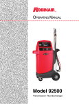
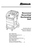
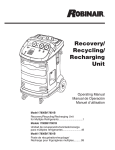
○ ○ ○ ○ ○ ○ ○ ○ ○ ○ ○ ○ ○ ○ ○ ○ ○ ○ ○ ○ ○ ○ ○ ○ ○ ○ ○ ○ ○ ○ ○ ○ ○ ○ ○ ○ ○ ○ ○ ○ ○ ○ ○ ○ ○ ○ ○ ○ ○ ○ ○ ○ ○ ○ ○ ○ ○ ○ ○ ○ ○ ○ ○ ○ ○ ○ ○ ○ ○ ○ ○ ○ ○ ○ ○ ○
Operating Manual
Model 34700Z / 17700Z
Recovery, Recycling, Recharging Unit
Model 34700Z / 17700Z
Recovery, Recycling, & Recharging Unit
SAFETY DEFINITIONS: Follow all WARNING, CAUTION, IMPORTANT, and NOTE messages in this manual. These messages
are defined as follows: WARNING means you may risk serious personal injury or death; CAUTION means you may risk personal
injury, property damage, or unit damage; IMPORTANT means you may risk unit damage; and NOTEs and OPERATING TIPS provide
clarity and helpful tips. These safety messages cover situations ROBINAIR is aware of. ROBINAIR cannot know, evaluate, and advise
you as to all possible hazards. You must verify that conditions and procedures do not jeopardize your personal safety.
DISCLAIMER: Information, illustrations, and specifications contained in this manual are based on the latest information available at
the time of publication. The right is reserved to make changes at any time without obligation to notify any person or organization of
such revisions or changes. Further, ROBINAIR shall not be liable for errors contained herein or for incidental or consequential damages
(including lost profits) in connection with the furnishing, performance, or use of this material. If necessary, obtain additional health
and safety information from the appropriate government agencies and the vehicle, refrigerant, and lubricant manufacturers.
WARNINGS
ALLOW ONLY QUALIFIED PERSONNEL TO OPERATE THE UNIT. Before operating the unit, read and follow
the instructions and warnings in this manual. The operator must be familiar with air conditioning and refrigeration
systems, refrigerants, and the dangers of pressurized components. If the operator cannot read English, operating
instructions and safety precautions must be read and discussed in the operator’s native language.
–Si el operador no puede leer inglés, las instrucciones de operación y las precauciones de seguridad deberán
leerse y comentarse en el idioma nativo del operador.
–Si l’utilisateur ne peut lire l’anglais, les instructions et les consignes de sécurité doivent lui être expliquées
dans sa langue maternelle.
PRESSURIZED TANK CONTAINS LIQUID REFRIGERANT. Do not overfill the internal storage vessel, because
overfilling may cause explosion and personal injury or death. Do not recover refrigerants into nonrefillable
containers; use only federally authorized refillable containers (DOT spec. 4BW or 4BA).
HOSES MAY CONTAIN LIQUID REFRIGERANT UNDER PRESSURE. Contact with refrigerant may cause
personal injury. Wear protective equipment, including safety goggles. Disconnect hoses using extreme caution.
DO NOT BREATHE REFRIGERANT AND LUBRICANT VAPOR OR MIST. Exposure may cause personal
injury, especially to the eyes, nose, throat, and lungs. Use the unit in locations with mechanical ventilation that
provides at least four air changes per hour. If accidental system discharge occurs, ventilate the work area before
resuming service.
DO NOT USE AN EXTENSION CORD. An extension cord may overheat and cause fire. If you must use an
extension cord, use the shortest possible cord with a minimum size of 14 AWG.
TO REDUCE THE RISK OF FIRE, do not use the unit in the vicinity of spilled or open containers of gasoline or
other flammable substances.
DO NOT USE COMPRESSED AIR TO PRESSURE TEST OR LEAK TEST THE UNIT OR VEHICLE AIR
CONDITIONING SYSTEM. Some mixtures of air and R-134a refrigerant are combustible at elevated pressures.
These mixtures are potentially dangerous and may result in fire or explosion causing personal injury or property
damage.
USE THE 34700Z UNIT WITH R-134a REFRIGERANT ONLY. The unit is designed to recover, recycle, and
recharge only R-134a refrigerant. Do not attempt to adapt the unit for another refrigerant. Do not mix refrigerant
types through a system or in the same container; mixing of refrigerants will cause severe damage to the unit
and the vehicle air conditioning system.
USE THE 17700Z UNIT WITH R-12 REFRIGERANT ONLY. The unit is designed to recover, recycle, and
recharge only R-12 refrigerant. Do not attempt to adapt the unit for another refrigerant. Do not mix refrigerant
types through a system or in the same container; mixing of refrigerants will cause severe damage to the unit
and the vehicle air conditioning system.
HIGH VOLTAGE ELECTRICITY INSIDE THE UNIT HAS A RISK OF ELECTRICAL SHOCK. Exposure may
cause personal injury. Disconnect the power before servicing the unit.
OPERATING NOTE: At temperatures exceeding 120° F / 49° C, wait 10 minutes between recovery jobs.
Table of Contents
Introduction . . . . . . . . . . . . . . . . . . . . . . . . . . . . . . . . . . . . . . . . . 2
Technical Specifications . . . . . . . . . . . . . . . . . . . . . . . . . . . 2
Keypad Functions . . . . . . . . . . . . . . . . . . . . . . . . . . . . . . . . 3
Glossary . . . . . . . . . . . . . . . . . . . . . . . . . . . . . . . . . . . . . . . 3
Menu Functions . . . . . . . . . . . . . . . . . . . . . . . . . . . . . . . . . 4
Setup . . . . . . . . . . . . . . . . . . . . . . . . . . . . . . . . . . . . . . . . . . . . . . 5
Select a Language . . . . . . . . . . . . . . . . . . . . . . . . . . . . . . . . 5
Select Operating Units . . . . . . . . . . . . . . . . . . . . . . . . . . . . 5
Add Oil to Vacuum Pump . . . . . . . . . . . . . . . . . . . . . . . . . 5
Fill the Internal Tank . . . . . . . . . . . . . . . . . . . . . . . . . . . . . 6
Operating Instructions . . . . . . . . . . . . . . . . . . . . . . . . . . . . . . . . . 7
Recover Refrigerant . . . . . . . . . . . . . . . . . . . . . . . . . . . . . . 7
Evacuate the A/C System . . . . . . . . . . . . . . . . . . . . . . . . . . 8
Replenish A/C System Oil . . . . . . . . . . . . . . . . . . . . . . . . . 9
Recharge the A/C System . . . . . . . . . . . . . . . . . . . . . . . . . 10
Equalize Hoses Procedure . . . . . . . . . . . . . . . . . . . . . . . . 10
Operating Instructions — Automatic Function . . . . . . . . . . . . . 12
Maintenance . . . . . . . . . . . . . . . . . . . . . . . . . . . . . . . . . . . . . . . . 14
General . . . . . . . . . . . . . . . . . . . . . . . . . . . . . . . . . . . . . . . 14
Replacing the Filter-Drier . . . . . . . . . . . . . . . . . . . . . . . . 14
Electrical Protection . . . . . . . . . . . . . . . . . . . . . . . . . . . . . 14
Changing Vacuum Pump Oil . . . . . . . . . . . . . . . . . . . . . . 15
Checking for Leaks . . . . . . . . . . . . . . . . . . . . . . . . . . . . . 15
Filling the Internal Tank . . . . . . . . . . . . . . . . . . . . . . . . . . 16
Replacement Parts . . . . . . . . . . . . . . . . . . . . . . . . . . . . . . 16
Safety Precautions . . . . . . . . . . . . . . . . . . . . . . Inside Front Cover
Warranty . . . . . . . . . . . . . . . . . . . . . . . . . . . . . . Inside Back Cover
CAUTION : This manual contains important safety procedures concerning the operation, use, and maintenance
of this product. Failure to follow the instructions contained in this manual may result in serious injury.
If you are unable to understand the contents of this manual, please bring it to the attention of your supervisor.
Do NOT operate this equipment unless you have read and understood the contents of this manual.
34700Z Recovery, Recycling, Recharging Unit
1
Introduction
The 34700Z model is used on R-134a vehicles; the 17700Z model is used on R-12 vehicles. Both
models are designed to be compatible with existing service equipment and standard service procedures.
Both models are UL-listed, single-pass systems that meet SAE specifications for recycled refrigerant.
Follow the SAE-J2210 recommended service procedure for the containment of R-134a; follow the
SAE-J1991 recommended service procedure for the containment of R-12.
The unit includes a 6 cfm (142 l/m) Robinair high vacuum pump for fast thorough evacuation. The
recovery compressor is not a vacuum pump. The compressor pulls the A/C system to a partial vacuum
only; use the unit’s vacuum cycle to remove moisture from the A/C system. (We recommend a
minimum 15-minute vacuum, or follow the vehicle manufacturer’s recommendation.)
Note : R-134a systems require special oils. Refer to the A/C system manufacturer’s service manual for
oil specifications.
High-Side Manifold Gauge –
connects to vehicle A/C system and
shows system’s high-side pressure.
Low-Side Manifold Gauge –
connects to vehicle A/C
system and shows system’s
low-side pressure.
Low-Side Flow Indicator –
an illuminated blue light
indicates low-side flow from
the vehicle A/C system
through the unit.
High-Side Flow Indicator – an illuminated
red light indicates high-side flow from the
vehicle A/C system through the unit.
Digital Display – the visual
interface between the operator
and the machine.
Main Power Switch –
supplies electrical
power to the unit.
Technical Specifications
Voltage . . . . . . . . . . . . . . . . . . . . . . . . . 115V, 60 Hz
Pump Free-Air Displacement . . . . 6 cfm (142 l/m)
Operating Range . . . . 50° to 120° F (11° to 49° C)
Dimensions . . . . . . . . . . . . . 50" H x 34" W x 23" D
. . . . . . . . . . . . . . . . . . (127 cm x 86.4 cm x 58.4 cm)
Filter-Drier . . . . . . . . . . . . . . . 43 cu. in. spin-on type
2
© 2003 SPX Corporation
Introduction
Keypad Functions
START
YES
START / YES begins or resumes a
function, or answers a query.
STOP
NO
STOP / NO terminates or pauses a
function, or answers a query.
MENU
MENU displays the selection menu.
START
YES
UP or DOWN arrows are used for
scrolling through menu items.
STOP
NO
AUTOMATIC
RECOVER
RECOVER activates the recovery
sequence.
MENU
VACUUM
VACUUM activates the vacuum and
automatic recycling sequence, followed by
an option to activate a vacuum leak check.
CHARGE
CHARGE charges the vehicle A/C
system with a programmed amount of
refrigerant.
INJECT OIL
AUTOMATIC
1 2 3
4 5 6
7 8 9
0
RECOVER
VACUUM
INJECT OIL
CHARGE
Keypad
INJECT OIL injects oil into the vehicle
A/C system.
AUTOMATIC activates a menu which
prompts the user through setting up an
automatic recover / vacuum / vacuum
leak check / charge sequence.
Glossary
A/C System : The vehicle air conditioning system being serviced.
Internal Storage Vessel : The refillable refrigerant storage vessel
designed specifically for this unit; 30 lb. (14 kg).
Source Tank : A disposable tank of new refrigerant used to refill
the internal storage vessel; not included.
Unit : The 34700Z or the 17700Z.
34700Z Recovery, Recycling, Recharging Unit
3
Introduction
Menu Functions
1. Press the MENU button on the keypad.
2. Press the UP or DOWN arrow key to scroll
through the menu choices shown on the second
line of the display :
SELECT LANGUAGE
VERSION X.XX
CHANGE DEFAULTS
CHANGE VACUUM PUMP OIL
VACUUM OIL TIME
CHANGE FILTER
FILTER CAPACITY
RECYCLE ONLY
TANK REFILL
SELECT UNITS IMPERIAL / METRIC
3. Press START / YES to make a choice from
the menu. Press STOP / NO to pause during
any process, and STOP / NO a second time to
exit a process.
Menu Choice : Select Language
Operator may choose to have prompts displayed in
one of three languages : English, Spanish, or French.
Menu Choice : Version X.XX
Displays the revision level of the software in the unit.
Menu Choice : Change Defaults
For service center use only.
Menu Choice : Change Vacuum Pump Oil
For maximum vacuum pump performance, change
vacuum pump oil after every 10 hours of operation.
Refer to the instructions outlined in the Maintenance
section under Changing Vacuum Pump Oil.
Menu Choice : Vacuum Oil Time
Displays how long the vacuum pump has operated
since the last oil change. The display resets to zero
after a vacuum pump oil change has been completed.
Refer to the instructions outlined in the Maintenance
section under Changing Vacuum Pump Oil.
Menu Choice : Select Units
Operator may choose to have test results displayed
in Imperial (English) or Metric units.
4
Start / Yes
Button
Stop / No
Button
UP
Arrow
Key
START
YES
STOP
NO
AUTOMATIC
Menu
Button
MENU
1 2 3
4 5 6
7 8 9
0
RECOVER
VACUUM
INJECT OIL
CHARGE
DOWN
Arrow Key
Menu Choice : Change Filter
The filter-drier removes acid, particulates, and
moisture from the refrigerant. Change the filter-drier
after 150 lbs. (68 kg) of refrigerant has been filtered.
Refer to the instructions outlined in the Maintenance
section under Replacing the Filter-Drier.
Menu Choice : Filter Capacity
Displays how many pounds or kilograms of refrigerant
have been recovered since the last filter change. The
display resets to zero after a filter-drier change. Refer
to the instructions outlined in the Maintenance section
under Replacing the Filter-Drier.
Menu Choice : Recycle Only
Manual recycling may be necessary if excessive air
and/or moisture has been recovered from the vehicle
A/C system.
Menu Choice : Tank Refill
This menu item is used to transfer refrigerant from
the source tank to the internal storage vessel (ISV).
Refer to the instructions outlined in the Maintenance
section under Filling the Internal Tank.
© 2003 SPX Corporation
Setup
The first time the unit is powered up, it will display the
initial setup mode.
1. Connect the power cord to the back of the unit, and
plug the other end into a correct voltage outlet.
2. Turn on the main power switch.
Select a Language
IMPORTANT : R-134a systems have
special fittings (per SAE specifications)
to avoid cross-contamination with R-12
systems. DO NOT adapt your unit for a
different refrigerant — system failure
will result.
The operator may choose to have prompts displayed in
one of three languages : English, Spanish, or French.
1. Use the UP or DOWN arrow key to toggle through
the choices for English, Spanish, or French. See
Figure 1.
Stop / No
Button
Start / Yes
Button
START
YES
2. Press START / YES to select the displayed
language choice.
Select Operating Units
The operator may choose to have test results displayed
in Imperial (English) units or Metric units.
1. Use the UP or DOWN arrow key to toggle through
the choices for IMPERIAL (English) UNITS or
METRIC UNITS.
2. Press START / YES to select the displayed
operating unit choice.
STOP
NO
AUTOMATIC
Arrow
Keys
MENU
1 2 3
4 5 6
7 8 9
0
RECOVER
VACUUM
INJECT OIL
CHARGE
Figure 1
Keypad
Add Oil to Vacuum Pump
Fill Port
IMPORTANT : The vacuum pump is shipped
without oil in the reservoir. Failure to add oil to
the vacuum pump will damage the pump.
1. Remove the plug from the vacuum pump fill port.
See Figure 2.
2. Attach the flexible tube and cap to the oil bottle, and
pour six (6) ounces of vacuum pump oil into the
vacuum pump fill port.
3. Press and release the START / YES key. While the
vacuum pump is running, slowly add oil until the
level rises to the center of the reservoir’s sight glass.
Sight Glass
Figure 2
Vacuum Pump
4. Press the STOP / NO key to stop the vacuum pump,
and install the plastic plug in the vacuum pump fill
port.
34700Z Recovery, Recycling, Recharging Unit
5
Setup
Fill the Internal Tank
1. Connect the service hoses to the unit, and
press START / YES. See Figure 3.
2. Connect the fill hose to a full source tank.
3. Open the source tank valve.
4. Install the source tank on the unit, and secure
the tank using the tank strap.
Note: If using a refillable tank, install the tank
upside down and connect the fill hose to the
vapor valve.
5. Press START / YES, and the unit will
automatically run a 5-minute vacuum to clear
all internal air.
HighSide
Hose
Low-Side
Hose
HIGH
LOW
Power
Cord
Fill
Hose
6. After the vacuum pump shuts off, the unit
automatically begins filling the internal
storage vessel. Add at least 8 lbs. (3.6 kg) of
refrigerant to ensure enough refrigerant is
available for charging.
Source
Tank
Strap
This process takes 15–20 minutes. The unit
stops when a sufficient amount of refrigerant
has been transferred to the internal tank, or
when the source tank is empty.
Press STOP / NO to pause. Press STOP /
NO again to exit, or START / YES to
resume.
7. When the fill process is complete, press
STOP / NO to exit. The unit is ready for
operation.
Figure 3
Side View
Note: There is no need to calibrate the scale; it
is calibrated at the factory.
6
© 2003 SPX Corporation
Operating Instructions
Recover Refrigerant
1. Empty the oil drain bottle located on the right-hand
side of the unit, if necessary, or make note of the
current oil level. See Figure 4.
2. Connect the high- and low-side hoses to the vehicle
A/C system.
3. Open the coupler valves on the hoses.
Oil Drain
Bottle
4. Press RECOVER.
5. When the system has recovered to a vacuum level of
approximately 13 in. Hg, the compressor
automatically shuts off. The unit goes into an
automatic oil drain—this may require 90 seconds to
complete.
Figure 4
6. After the oil drain is complete, the display alternates
between :
RECOVER COMPLETE
CHECK OIL BOTTLE
RECOVERED XX.XX LBS. (X.XX KG)
Note: The displayed recovered weight can vary
depending on ambient conditions, and should not be
used as an indicator of scale accuracy.
Operating Tips
•
LOW SYSTEM PRESSURE
7. Check the oil drain bottle, and note the amount of oil
that was removed from the A/C system. This is the
amount of oil that must be charged into the A/C
system after evacuation is complete.
8. A pressure rise may occur if there was freezing in
the A/C system during recovery.
until pressure increases, or the START /
YES button is pressed. Verify the high- and
low-side hoses are connected and the
coupler valves are open. Press STOP / NO
to exit at this point.
•
To ensure complete recovery of refrigerant, the unit
will automatically wait 5 minutes and monitor for a
rise in pressure above 0 in. Hg.
Note: The high- and low-side lights on the control
panel will remain ON until the recovery is complete.
9. Press STOP / NO to exit.
Recovery is complete. You are now ready to make
repairs to the A/C system, if necessary, or advance to
the evacuation process.
34700Z Recovery, Recycling, Recharging Unit
After selecting the RECOVER function, if
150 lbs. (68 kg) or more of refrigerant has
been recovered since the last filter-drier
change, the display reads
FILTER WEIGHT XXX LB (XX KG)
CHANGE FILTER NOW?
If a rise occurs, the unit will repeat the recovery
process, and wait another 2 minutes for a pressure
rise above 0 in. Hg.
The unit will continue to recover and wait until it
maintains a vacuum for 2 minutes.
After selecting the RECOVER function, if
system pressure is below 25 psi, the display
reads
Refer to the Filter Change Procedure in
Maintenance section of this manual for
details regarding replacing the filter.
•
After selecting the RECOVER function, if
the unit has refrigerant in the low-side
plumbing, it begins a clearing process and
displays
CLEARING IN PROGRESS
If you wish to skip the clearing operation,
or stop the clearing prematurely, press
START / YES.
7
Operating Instructions
Evacuate the A/C System
1. Ensure service hoses are connected, and the coupler
valves are OPEN.
Operating Tips
•
2. Press VACUUM.
VACUUM OIL TIME XX:XX
CHANGE OIL NOW?
3. Press START / YES to accept the default
evacuation time of 15 minutes, or enter the desired
vacuum time using the number keys, and press
START / YES.
The unit pulls a vacuum on the vehicle A/C system to
remove any air and boil off any moisture that may be
present in the system.
Refer to the Maintenance section of this
manual for instructions regarding Changing
Vacuum Pump Oil.
•
Press any key to exit, and recover refrigerant
before proceeding.
•
4. The unit will give you the option of doing a leak
check after evacuation.
Press STOP / NO to skip the leak check and begin
evacuation.
You are now ready to replenish the A/C system oil, if
necessary, or to recharge the system with refrigerant.
If a leak check was selected at the end of
vacuum, and a leak is detected, the unit
displays
LEAK CHECK FAILED
PRESS ANY KEY TO EXIT
Press START / YES to perform the leak check.
Press STOP / NO to pause the process. Press
START / YES to resume, or STOP / NO again
to exit.
Before the unit begins evacuating the A/C
system, it checks for any pressure in the
system that might damage the vacuum pump.
If pressure is detected, the unit displays
PRESSURE EXISTS
PRESS ANY KEY TO EXIT
IMPORTANT : Evacuate the system for at least
15 minutes, or follow the A/C system
manufacturer’s specifications, to ensure
adequate moisture and contaminant removal.
5. The unit evacuates the A/C system and stops when
the specified time has elapsed.
If the vacuum pump has run for 10 or more
hours without an oil change, the unit displays
Press any key to exit the evacuation, perform
needed repairs, and repeat evacuation.
•
To ensure an accurate leak test, it is
imperative that a thorough recovery and
evacuation of the system has been performed.
During the recovery process, cold spots can
develop in the automotive system. Pockets of
refrigerant in desiccant and in system oil will
continue to vaporize as the A/C system
temperature equalizes toward ambient. As
this occurs, A/C system pressure will
increase, which may be interpreted by the
unit as a leak.
This will vary somewhat with ambient
temperature conditions.
8
© 2003 SPX Corporation
Operating Instructions
Replenish A/C System Oil
Oil may be replenished through the high side after the
vacuum function, or with an oil inject tool after
charging the vehicle.
IMPORTANT : To prevent damage to
equipment, charge only the amount of oil that
was removed from the A/C system during the
recovery process. If no oil was removed from
the A/C system during recovery, DO NOT
charge any oil into the A/C system.
Empty the oil drain bottle before recovering an A/C
system to prevent an inaccurate oil charge.
1. Refer to the vehicle service manual to determine the
correct oil for the A/C system being serviced.
Oil Injector
Bottle
2. Check the oil drain bottle to determine the amount of
oil that was removed. See Figure 5.
3. Adjust the o-ring around the oil injector bottle to the
required oil charge level.
For example, if the bottle’s oil level is at 4 ounces,
and you need 1/2 ounce of oil to replenish the A/C
system, place the o-ring at the 3-1/2 ounce level.
O-ring
4. Attach the oil injector bottle to the unit.
5. Press the INJECT OIL button. The unit looks for
pressure in the hoses, and temporarily displays
EQUALIZING PRESSURE.
6. When prompted, press and hold INJECT OIL until
the oil level in the oil injector bottle reaches the o-ring.
7. Press STOP / NO after the oil inject is complete to
recharge the system with refrigerant. The display
will prompt into the charge mode. (Charge mode
after injecting oil will only allow a high-side charge.)
Oil Drain Bottle
Figure 5
Note: You must recharge the A/C system with
refrigerant at this time to ensure all the oil is
delivered.
34700Z Recovery, Recycling, Recharging Unit
9
Operating Instructions
Recharge the A/C System
If an oil inject has already been performed, you
may skip steps 1 and 2.
1. Press CHARGE.
2. Select START / YES, to perform an oil inject;
select STOP / NO to skip the oil inject.
Operating Tips
After selecting the CHARGE function and
entering a desired weight, if the weight entered
will leave less than 3 lbs. (1.36 kg) of
refrigerant in the internal tank after charge, the
charge function will not start. The display reads
INSUFFICIENT REFRIG.
PRESS ANY KEY TO EXIT
3. Press CHARGE to toggle between a high-side or
low-side charge.
Refer to the Maintenance section of this manual
for instructions on Refilling the Internal Tank.
Note: Charge mode after injecting oil will only allow a
high-side charge.
Slow Charge Procedure
4. Accept either the default weight by pressing START
/ YES, or type in a weight, using the number keys,
and press START / YES.
5. After a valid charge weight is entered, the display
reads
CHARGE IN PROGRESS / DO NOT DISTURB
CHARGED=X.XX LBS. (X.XX KG)
Moving or bumping the unit at this point may result
in an incorrect reading.
6. When the charge is complete, the display reads
EQUALIZE HOSES?
X.XX LBS (KG) CHARGED
Press START / YES to equalize hoses. Press
STOP / NO to resume charging.
Equalize Hoses
After the charge is complete, the user has the option to
equalize the pressure in the hoses to ensure a more
accurate charge. If the pressure in the high side and low
side is not equal after charge, then it may be necessary
to follow this procedure to ensure all the liquid
refrigerant trapped in the service hoses is transferred to
the vehicle A/C system.
If, during the CHARGE cycle, the weight fails
to charge 0.05 lbs. (0.02 kg) in 30 seconds, it
may be necessary to use the vehicle to pull the
charge into the A/C system. The unit “beeps”
while the display alternates between
CHARGE HAS SLOWED
RETRY? (YES/NO)
1. If START / YES is pressed, the unit will
ask if you want to use the vehicle to pull in
the charge.
Selecting START / YES will prompt the
user through the slow charge procedure.
Selecting STOP / NO will resume charging.
2. Place the vehicle gear selector in park or
neutral, with the emergency brake ON.
3. Start the vehicle. Set the A/C system to its
maximum setting.
4. Press START / YES. The unit charges out
of the low-side inlet only, allowing the
vehicle’s compressor to pull the refrigerant
into the A/C system. When the charge is
complete, the display shows
EQUALIZE HOSES?
X.XX LBS (KG) CHARGED
1. After the charge is complete, the user has the option
to equalize the pressure in the hoses.
Selecting START / YES prompts the user through
the EQUALIZE HOSES procedure.
Select STOP / NO to resume charging.
2. Close the high-side coupler valve.
10
© 2003 SPX Corporation
Operating Instructions
Equalize Hoses contd.
3. Place the vehicle gear selector in park or neutral,
with the emergency brake ON.
4. Start the vehicle. Set the A/C system to its maximum
setting.
5. Press START / YES. The unit internally connects
the low- and high-side hoses, allowing the vehicle’s
compressor to pull the refrigerant into the A/C
system. When the charge is complete, the display
shows
WARNING : To prevent personal
injury, verify the vehicle is in park or
neutral with the emergency brake ON
before starting the engine. Never run
a vehicle without adequate ventilation
in the work area.
CLEAR COMPLETE
X.XX LBS (KG) CHARGED
6. Close the low-side coupler valve. Remove the
service hoses from the A/C system. Shut OFF
the vehicle.
The A/C system is now ready for use.
34700Z Recovery, Recycling, Recharging Unit
11
Operating Instructions – Automatic
The automatic function allows a user to program an
automatic recovery, vacuum, leak test, and / or charge
sequence. The user may choose to skip any step in the
automatic operation during the programming. A total
automatic sequence may take an hour to complete.
Note: Oil recovered during the recovery cycle can be
injected by the user before the charge cycle, or can be
manually injected into the vehicle after charge using a
separate oil injection tool.
START
YES
STOP
NO
Automatic
Function
AUTOMATIC
1. Connect the high- and low-side service hoses to
the A/C system, and open the coupler valves on
the hoses.
2. Press AUTOMATIC.
MENU
1 2 3
4 5 6
7 8 9
0
RECOVER
VACUUM
INJECT OIL
CHARGE
3. The unit will ask if a recovery is needed.
Press STOP / NO to skip the recovery cycle.
Press START / YES to accept.
4. The unit will ask if vacuum is needed for evacuation.
Press STOP / NO to skip the vacuum cycle.
Press START / YES to accept.
If START / YES is selected, press the START / YES
key again to accept the default evacuation time of 15
minutes, or enter the desired evacuation time by using
the number keys, and press START / YES again.
5. If vacuum has been selected, the unit will ask if a
leak check is needed.
Press STOP / NO to skip the leak check.
Press START / YES to accept.
6. The unit will ask if a charge is needed.
Press STOP / NO to skip the charge cycle.
Press START / YES to accept a charge. Press
CHARGE to toggle between high- or low-side
charge, or both.
Accept either the default weight by pressing
START / YES, or type in a desired weight using
the number keys, and then press START / YES.
7. The display will show an overview of all the tests
that were selected. Press START / YES to begin the
automatic sequence.
12
Operating Tips
If the weight entered will leave less than 3 lbs.
(1.36 kg) of refrigerant in the internal tank after
charge, the charge function will not start. The
display reads
INSUFFICIENT REFRIG.
PRESS ANY KEY TO EXIT
Refer to the Maintenance section of this manual
for instructions on Refilling the Internal Tank.
© 2003 SPX Corporation
Operating Instructions – Automatic
Automatic Function contd.
Note :
• If a high-side charge has been selected, before
charging, the automatic sequence will pause and
“beep” for 30 seconds to allow the user to inject oil,
if desired. See Replenishing the A/C System Oil
instructions in this manual.
Operating Tips
•
If problems are encountered during the
automatic sequence, the unit will “beep”
three times, and the control panel readout
will pinpoint the problem encountered. The
sequence will remain paused until the user
enters a decision regarding how to proceed.
•
Before the unit begins evacuating the A/C
system during the automatic sequence, it
checks for any pressure in the system that
might damage the vacuum pump. If pressure
is detected, the unit displays
• After charging is complete, the user also has the
option to equalize the hoses. Refer to the Equalize
Hoses Procedure in this manual.
8. When the sequence is complete, the display will
show the amount of refrigerant that was recovered
and charged.
PRESSURE EXISTS
PRESS ANY KEY TO EXIT
9. Close the high- and low-side coupler valves, and
remove the service hoses from the A/C system.
10. If any oil was recovered during the recovery cycle,
and the user did not inject oil before the charge
cycle, manually inject oil into the A/C system at this
time using an oil injection tool.
Press any key to exit the automatic sequence.
•
If a leak check was selected at the end of
vacuum, and a leak is detected, the unit
displays
LEAK CHECK FAILED
PRESS STOP TO EXIT
PRESS START TO CONTINUE
Press stop to exit the automatic sequence,
and perform needed repairs. Press start to
continue the automatic sequence despite the
failed leak check.
•
To ensure an accurate leak test, it is
imperative that a thorough recovery and
evacuation of the system has been
performed. During the recovery process,
cold spots can develop in the automotive
system. Pockets of refrigerant in desiccant
and in system oil will continue to vaporize as
the A/C system temperature equalizes toward
ambient. As this occurs, A/C system pressure
will increase, which may be interpreted by
the unit as a leak.
This will vary somewhat with ambient
temperature conditions.
34700Z Recovery, Recycling, Recharging Unit
13
Maintenance
General Maintenance
1. On a regular basis, wipe off the unit using a clean cloth to remove grease and dirt.
2. Periodically check internal components for leaks; over time, fittings can loosen as the unit is moved.
Open the door panel, and trace lines using a leak detector. Check connections on the back of the unit
also. Tighten any loose fittings or connections you may find.
Replacing the Filter-Drier
The filter-drier on this unit is designed to trap acid and
particulates, and to remove water from refrigerant.
Change the filter-drier after every 150 lbs. (68 kg) of
refrigerant has been recycled to ensure adequate
moisture and contaminant removal. (The unit will
prompt the user to change the filter-drier after 150 lbs.
of refrigerant has been recycled.)
Filter-Drier
IMPORTANT : For best results, use Robinair
filter-driers. All performance tests and claims
are based on using the filter-drier specified for
this unit. Using a different filter-drier may affect
the performance of the unit and test results.
Order Robinair No. 34724.
1. Press MENU.
2. Scroll through the menu to CHANGE FILTER, and
press START / YES. The unit will begin clearing
the filter.
3. When clearing is complete, the display reads TURN
UNIT OFF AND REPLACE FILTER. Turn OFF
main power, and unplug the machine.
4. Open the unit door, and replace the old filter with a
new filter.
5. Close the unit door, plug in the machine, and turn
ON main power.
The filter-drier change is now complete.
Rear View (without shroud)
Operating Tips
The menu item FILTER CAPACITY
displays how many pounds or kilograms of
refrigerant have been recovered since the
last filter change :
FILTERED=XXX LBS (KG).
The amount filtered resets to zero after a
the filter-drier has been changed.
Electrical Protection
The unit is equipped with two circuit breakers (15 amp
and 3 amp) on the back panel. If either breaker trips, its
button will pop out. A tripped 3 amp breaker will
render the fan inoperable; a tripped 15 amp breaker will
cause the unit to lose all power.
Press the circuit breaker button to reset.
14
© 2003 SPX Corporation
Maintenance
Changing Vacuum Pump Oil
Fill Port
For maximum vacuum pump performance, change the
vacuum pump oil after every 10 hours of operation. The
unit will prompt the user to perform a vacuum pump oil
change after 10 hours of operation.
1. Press MENU.
2. Use the arrow keys to select CHANGE VACUUM
PUMP OIL, and press START / YES to begin.
3. Allow the vacuum pump to run until it automatically
stops (about 2 minutes).
4. Remove the plastic plug on the oil fill port of the
vacuum pump.
5. Remove the oil drain cap from the vacuum pump,
and drain the oil into a suitable container for
disposal. Replace the oil drain cap.
6. Attach the flexible tube and cap to the oil bottle,
and pour six (6) ounces of vacuum pump oil into
the fill port.
Oil Drain Fitting
Sight Glass
Operating Tips
The menu item VACUUM OIL TIME
displays how long the vacuum pump has
operated since the last oil change :
OIL TIME=XX:XX
7. Press START / YES. While the vacuum pump is
running, slowly add oil until the level rises to the
center of the reservoir’s sight glass.
The time resets to zero after a vacuum pump
oil change has been completed.
8. Press STOP / NO.
Review current local, state, and
federal statutes, cases, laws, and
regulations to determine the correct
disposal procedure for pump oil. It is
the responsibility of the user to
determine if a material is a hazardous
waste at the time of disposal. Ensure
you are in compliance with all
applicable laws and regulations.
9. Replace the plastic plug on the fill port.
The unit is now ready for operation.
Checking for Leaks
Check the unit for leaks every three months, or as
specified by local or state laws.
1. Turn off MAIN POWER.
2. Disconnect the power cord from the outlet.
3. Open the rear door.
4. Remove the top cover and front panel.
5. Use a leak detector to probe all connections for
refrigerant leaks. Tighten fittings if a leak is
indicated.
6. Reassemble the body panels, and close the rear door.
Inspect the unit periodically for leaks. The
manufacturer does not reimburse for lost
refrigerant.
34700Z Recovery, Recycling, Recharging Unit
15
Maintenance
Filling the Internal Tank
This menu item is used to transfer refrigerant from the
source tank to the internal storage vessel (ISV).
1. Connect the fill hose to a full source tank.
2. Open the source tank valve.
HighSide
Hose
3. Install the source tank on the unit, and secure the
source tank using the tank strap.
Low-Side
Hose
Note: If using a refillable tank, install the tank upside
down and connect the fill hose to the vapor valve.
HIGH
LOW
4. Press Menu, and use the UP or DOWN arrow keys
to select TANK REFILL.
Power
Cord
5. Press START / YES, and the unit will automatically
fill the internal storage vessel until it contains 15 lbs.
of refrigerant, or until the source tank is empty.
Fill
Hose
Press STOP / NO to pause. Press STOP / NO again
to exit, or START / YES to resume.
Source
Tank
Strap
Note : If a refrigerant source tank remains connected
to the unit during normal operation, the correct
amount of refrigerant will be automatically
maintained in the ISV. The ISV may be manually
refilled, if necessary.
6. When the fill process is complete, press STOP / NO
to exit. The unit is ready for operation.
Side View
Replacement Parts
16
Component
34700Z
Replacement
Part No.
17700Z
Replacement
Part No.
96" Red Hose
63096
68396A
96" Blue Hose
62121
68296A
Filter-Drier
34724
34724
Low-Side Coupler
18190A
High-Side Coupler
18191A
Vacuum Pump Oil
(case of 12 quarts)
13203
13203
Vacuum Pump Oil
(case of 4 gallons)
13204
13204
Maintenance Kit
13172
13172
© 2003 SPX Corporation
Robinair Limited Warranty Statement
Rev. November 1, 2005
This product is warranted to be free from defects in workmanship, materials, and components for a
period of one year from date of purchase. All parts and labor required to repair defective products
covered under the warranty will be at no charge. The following restrictions apply:
1. The limited warranty applies to the original purchaser only.
2. The warranty applies to the product in normal usage situations only, as described in the Operating
Manual. The product must be serviced and maintained as specified.
3. If the product fails, it will be repaired or replaced at the option of the manufacturer.
4. Transportation charges for warranty service will be reimbursed by the factory upon verification of the
warranty claim and submission of a freight bill for normal ground service. Approval from the manufacturer must be obtained prior to shipping to an authorized service center.
5. Warranty service claims are subject to authorized inspection for product defect(s).
6. The manufacturer shall not be responsible for any additional costs associated with a product failure
including, but not limited to, loss of work time, loss of refrigerant, cross-contamination of refrigerant,
and unauthorized shipping and/or labor charges.
7. All warranty service claims must be made within the specified warranty period. Proof-of-purchase
date must be supplied to the manufacturer.
8. Use of recovery/recycling equipment with unauthorized refrigerants or sealants will void warranty.
• Authorized refrigerants are listed on the equipment or are available through the Technical Service
Department.
• The manufacturer prohibits the use of the recovery/recycling equipment on air conditioning (A/C)
systems containing leak sealants, either of a seal-swelling or aerobic nature.
This Limited Warranty does NOT apply if:
•
•
•
The product, or product part, is broken by accident.
The product is misused, tampered with, or modified.
The product is used for recovering or recycling any substance other than the specified refrigerant
type. This includes, but is not limited to, materials and chemicals used to seal leaks in A/C systems.
CONVERSION
TABLE
OZ.
0.5
1.0
1.5
2.0
2.5
3.0
3.5
4.0
4.5
5.0
5.5
6.0
6.5
7.0
7.5
8.0
8.5
9.0
9.5
10.0
10.5
11.0
11.5
12.0
12.5
13.0
13.5
14.0
14.5
15.0
15.5
16.0
LBS.
0.03
0.06
0.09
0.13
0.16
0.19
0.22
0.25
0.28
0.31
0.34
0.38
0.41
0.44
0.47
0.50
0.53
0.56
0.59
0.63
0.66
0.69
0.72
0.75
0.78
0.81
0.84
0.88
0.91
0.94
0.97
1 lb.
%
Visit our web site at
www.robinair.com
or
Call our Toll-Free
Technical Support Line at
800-822-5561
in the continental U.S. or Canada.
In all other locations, contact your local distributor. To help us serve
you better, please be prepared to provide the model number, serial
number, and date of purchase of your unit.
To validate your warranty, complete the warranty card attached to
your unit, and return it within ten days from date of purchase.
NATIONWIDE NETWORK OF AUTHORIZED SERVICE CENTERS
If your unit needs repair or replacement parts, contact the service
center in your area. For help in locating a service center, call the
toll-free technical support line.
Due to ongoing product improvements,
we reserve the right to change design,
specifications, and materials without notice.
The 34700Z / 17700Z units are designed to meet all applicable agency certifications, including
Underwriter's Laboratories, Inc., SAE Standards, and CUL.
Certain state and local jurisdictions dictate that using this equipment to sell refrigerant by
weight may not be permitted. We recommend charging for any A/C service by the job
performed.
This weight scale provides a means of metering the amount of refrigerant needed for optimum
A/C system performance as recommended by OEM manufacturers.
SPX Corporation
655 Eisenhower Drive
Owatonna, MN 55060-0995 USA
Tech Services: 1-800-822-5561
Fax: 1-412-690-2001
Customer Service: 1-800-533-6127
Fax: 1-800-322-2890
Web site: www.robinair.com
523040 (Rev. C, November 17, 2005)
© 2003 SPX Corporation