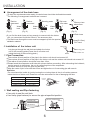
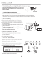
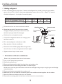
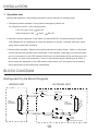
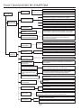
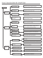
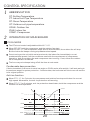
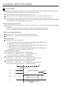
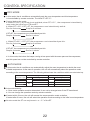
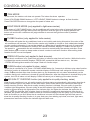
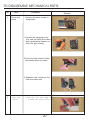
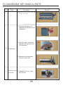
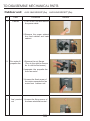
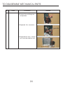
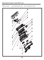
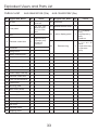
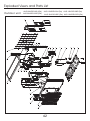
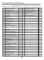
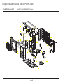
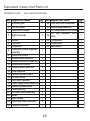
1
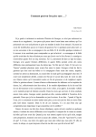
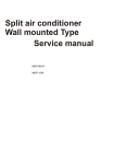
Split air conditioner
Wall mounted Type
Service manual
AUS-09H53R120P*(Db5)
AUS 12H53R120P*(Da4)
AUS-18H53R120C*(Da)
AUS-24H53R230T*(Da)
CONTENTS
Contents
1
Safety precautions
2
Installation
2
Blo ck dia gram
10
Trouble shootin g
11
Trouble solve methods
12
Fault dia gnosis by symptom
16
Control specific atio n
20
To disassemble mechanical parts
26
Exploded views and parts list
32
Wiring diagrams
48
1
SAFETY PRECAUTIONS
The following safety precautions must be taken when using your air
conditioner.
1. Warning: Prior to repair, disconnect the power cord.
2. Use proper parts: use only exact replacement parts. (Also, we recommend replacing parts rather
than repairing them.)
3. Use the proper tools: use the proper tools and test equipment, and know how to use them. Using
defective tools or test equipment may cause problems later-intermittent contact, for example.
4. Power cord: prior to repair, check the power cord and replace it if necessary.
5. Avoid using an extension cord, and avoid tapping into a power cord. This practice may result in
malfunction or fire.
6. After completing repairs and reassembly, check the insulation resistance.
Procedure: prior to applying power, measure the resistance between the power cord and the ground
terminal. The resistance must be greater than 30 megohms.
7. Make sure that the grounds are adequate.
8. Make sure that the installation conditions are satisfactory. Relocate the unit if necessary.
9. Keep children away from the unit while it is being repaired.
10. Be sure to clean the unit and its surrounding area.
INSTALLATION
Selecting area for installation
Select an area for installation that is suitable to the customers needs.
1 Location of indoor unit
Keep the air inlet and outlet at a far distance from the blockage.
Keep the height distance between the indoor and outdoor unit at most 5m.
Mount on the wall solid enough to bear the weight of the unit and not cause any shake.
Avoid direct sunshine.
A place easy for condensate drain and easy for connecting with the outdoor unit.
Keep a far distance away from the fluorescent lamp, it may influence the operation of remote controller.
Keep at least 1m away from the TV radio and other home appliances.
2 Location of outdoor unit
A place solid enough to bear the weight of the unit and not cause any shake.
Good ventilation, less dust, far from direct rain and sunshine.
A place where the air discharged out of the outdoor unit or the operation noise will not annoy your
neighbours.
No blockage near the outdoor unit.
Avoid places close to inflammable gas leakage.
Caution:
It is harmful to the air conditioner if it is used in the following environments: greasy areas (including area
near machines). Salty area such as coastal areas, areas where sulfuric gas is present such as hot spring
areas. Contact your dealer for advice.
2
INSTALLATION
Installation diagram of indoor unit and outdoor unit
Confirm the installation position by the mark of the indoor mounting plate.
105m
above
m
155mm
above 250mm
above
Above 20mm
The copper pipe can be led
from back, right, underside,
or left-back side.
back
right
front
left
back
Underside Left-back
above 500mm
While installing the pipeline on the
thin armor plate or on the wall of
metal mesh, you should use the
wooden board to clamp between
the wall and the pipeline, or wrap
up the pipeline with 7-8 layers of
insulating plastic tape.
a b ov
e 30
a bo
m
上0m
以
30
0vmme
a1b0o
0 mm
ve 5
Notice: do not elevate the
drain hose.
m
00m
abo
ve 5
0
0 mm
3
Cover connecting pipe with
adiabatic material.
Sponge plastic adiabatic
material with the
thickness of 8mm.
INSTALLATION
1 Securing the mounting plate and drill on the wall
Secure the mounting plate
The mounting plate should be attached to the structural part of wall (post etc).
fasten string at the central hole at least 250mm
at least 140mm
40mm
at least 180mm
Center of hole( 65mm)
plumb
120mm
Pipe hole
Center of hole( 65mm)
NOTICE:
The holes at solid arrow position must be secured to avoid the shake of mounting plate.
When the expansion bolts are used, two holes ( 11×20 or 11×26 ) that the distance
between them is 450mm should be adopted.
Confirm the position of holes, and drill holes on the wall.
2 Wiring
Open the front grille;
Remove the screw from electrical box cover, pull the
Screw
electrical box cover away from the unit and set aside.
Remove the screw from fastener, pull the fastener
away from the unit and set aside.
Connect the cable.
Indoor unit terminal
Replace the fastener and electrical box cover.
Diagram
Connecting cable
NOTE:
The appliance shall be installed in accordance with national wiring regulations.
The appliance must not be installed in the laundry.
The appliance must be installed 2.3m above the floor.
The appliance must be positioned so that the plug is accessible.
For some models whose cooling capacity are above 4600W (17000BTU/h),
an all-pole disconnection device which has at least 3mm separation distance in
all pole and a residual current device(RCD)with the rating of above 10mA shall
be incorporated in the fixed wiring according to the national rule.
4
INSTALLATION
3 Installation of the drain hose
Liquid pipe
NOTE:
The drain hose must be arranged beneath the copper pipe.
The drain hose must not be hunched or twisted.
While wrapping up the drain hose, do not pull it.
The drain hose through the room must be wrapped up by the
thermal insulation materials.
The copper pipe and the drain hose must be wrapped up by felt
strip. Adiabatic pad should be used at where the pipe contacts
the wall.
gaspipe
Drain hose
Adiabatic
underlay
felt
ROUTE OF PIPE
If pipe comes out of the right side of the indoor unit, cut part
“1” of the unit;
If pipe comes out of the lower-right side of the indoor unit, cut
part “2” of the unit;
If pipe comes out of the left side of the indoor unit, cut part “3”
of the unit.
1
3
2
REFIT OF DRAIN HOSE
If pipe comes out of the left side of the indoor unit, the drain hose
must be refitted, otherwise water leakage may occur.
Refit methods: Interchange the position of drain hose and drain
rubber plug.
Clearance is not allowed after refit, it would lead to water leakage.
5
drain hose
Drain rubber
plug
INSTALLATION
Arrangement of the drain hose
To drain the condensate water easily, the drain hose should be declined downwards.
The following 5 arrangement methods are incorrect.
Decline
downward
Decline
downward
Dip hose
into water
Standing water
air
Water
leak
(Fig. 1)
Water
leak
(Fig. 2)
50mm or less
above floor
Water
leak
(Fig. 5)
(Fig. 4)
(Fig. 3)
Drain hose
If you find the drain hose not long enough to connect with the indoor
unit, you can extend it with the hoses in the accessory box.
The drain hose through the room must be wrapped up with the special
adiabatic material.
4 Installation of the indoor unit
Hose(ID 15cm)
PVC hard
Indoor unit
Let pipe go through the wall hole and attach the indoor
unit to the mounting plate.(Press the rib of indoor unit
inside the hook of the mounting plate.)
the mounting plate
Bottom
the rib of indoor unit
5 Pipe Connection
The number of bent position of the pipe in the indoor unit should not exceed 10.
The number of bent position of the pipe in the indoor unit and the outdoor unit should not exceed 15.
The radius of bent position should be more than 10cm.
Please break the evaporator craft tube with pincers before connecting. After exhausting the inside air,
use the wrench to twist down the nut of connecting tube of the evaporator.
Put some seal oil to cover the joint and the flare.
Align the centre of joint in line with that of flare and tighten the nut of connecting pipe with wrench.
Attention:
Do not exhaust the inside air just by loosing the nut since there is the air of certain pressure
inside the tube of indoor unit. Please do not make extra effort for fear of damaging the flare.
DIAMETER OF PIPE
6.35mm ( 1/4”)
9.52mm ( 3/8”)
TORQUE(N·m)
13.7---17.6
34.3---41.2
12.7mm ( 1/2”)
15.88mm ( 5/8”)
49.0---56.4
73.0---78.0
Evaporator
craft tube
6 Wall sealing and Pipe fastening
Use putty to seal the wall hole.
Use clamp (pipe fastener) to secure the pipe at specified position.
get rid of unwanted part
clamp
seal with putty
secure the connecting
pipe with clamp
Indoor unit
screw
6
INSTALLATION
Installation diagram of indoor unit and outdoor unit
1 Wiring
Outdoor unit terminal
Connecting
cable
Notice:
If the signal wire has to be bought separately, choose electric wire above 0.75mm.
If the interconnection cord for power supply has to be replaced, please see the
following table for reference.
SPECS (Interconnection cord)
MODEL
≤2700W(10000BTU/h)
≥1.0mm
2
3000W(11000BTU/h) -4000W(15000BTU/h)
≥1.5mm
2
4500W(18000BTU/h) -8000W(28000BTU/h)
≥2.5mm
2
WARNING:
Please take the electric circuit diagram attached to the indoor/outdoor units as major
reference while installing.
The power wire and signal wire between the indoor/outdoor units must be connected
one by one as per corresponding number on the wiring terminal board.
The connecting cables must be clipped together.
Special cable must be used to connect indoor unit and outdoor unit. It should be ensured
that the terminals are not influenced by external force. Poor connection may cause fire.
The electric box cover must be mounted and secured in position, otherwise fire or electrical
shock may occur because of dust or moisture.
The temperature of refrigerant circuit will be high, please keep the interconnection cable away
from the copper tube.
7
INSTALLATION
2 Installation of the drain joint(only for heat pump type)
Insert the outdoor double-channel drain joint in one of the
bottom holes of the suitable size then connect drain hose
and joint together.
Bottom
Double-channel
drain joint
Drain hose
3 Joint of the connecting pipe
Put some seal oil to cover the joint and the flare.
Align the centre of joint in line with that of flare and tighten the nut of connecting pipe
with wrench. ( Adjust the torque by the same method of connecting pipe for indoor unit.)
4 Air exhausting
Screw down the cap of both gas shut-off valve and
liquid shut-off valve as well as the nut of service port.
Connect the centre hose of the manifold gauge to
the vacuum pump.
Manifold Gauge
Connect the manifold gauge to the outdoor unit gas
line port as shown.
Turn the vacuum pump on for about 10-15 minutes
in order to evacuate the air.
Close the manifold valve, then turn off the vacuum
pump and disconnect the hose.
3-Way Valve
Replace the cap on the 3-way valve.
Vacuum Pump
Set both the liquid and gas line valves to fully
open position with the hexagonal wrench for
the unit operation.
Re-install the valve caps.
5 Process of flared tube
Use the pipe cutter to cut off the broken part of flare.
Remove burrs at the cut of the flare.
Copper pipe
90
Insert a nut into the connecting pipe and do flaring
with specified flaring tools, reamers for example.
Remove burrs at the cut of the flare.
Outer diameter
6.35mm ( 1/4”)
9.52mm ( 3/8”)
12.7mm ( 1/2”)
15.88mm(5/8”)
Burr
A(mm)
2.0--2.5
3.0--3.5
3.5--4.0
D
4.0--4.5
Check the quality of flaring technique.
8
A
Oblique
Roughness
Reamer
Burr
INSTALLATION
6 Adding refrigerant
If the connecting pipe is longer than 7 metres, add refrigerant as needed. (Cool only type) added
amount A=(Lm-7m)×15g/m ; (Heat pump type)added amount A= (Lm-7m) ×50g/m. ( A: amount
of added refrigerant, L: the length of connecting pipe)
The length of connecting pipe (m)
7
8
9
10
(Cool only type)added amount (g)
0
15
30
45
(Heat pump type)added amount (g)
0
50
100
150
Exhaust the air as the above-mentioned method.
Manifold gauge
Screw the gas shut-off valve to close, connect
Low pressure
valve
charging hose(low pressure) to the service valve
and then open gas shut-off valve again.
Set the unit to cool operation mode.
Pressure meter
High pressure
valve
Charging line
Connect the refrigerant bottle to the charging hose
and then convert it.
Fill in liquid refrigerant as the above table.
Service port
Stop operation of the air conditioner.
Disconnect the manifold gauge after turning off the
shut-off valve, and then open gas shut-off valve again.
Tighten nuts and caps of each valve.
7 Relocation of the air conditioner.
Refer to this procedure when the unit is relocated.
1. Carry out the pump down procedure.
2. Remove the power cord.
3. Disconnect the assembly cable from the indoor and outdoor units.
4. Remove the flare nut connecting the indoor unit and the pipe.
At this time, cover the pipe of the indoor unit and the other pipe using a cap or vinyl plug to avoid foreign
material entering.
5. Disconnect the pipe connected to the outdoor unit.
6. Make sure you do not bend the connection pipes in the middle and store together with the cables.
7. Move the indoor and outdoor units to a new location.
8. Remove the mounting plate for the indoor unit and move it to a new location.
9
INSTALLATION
8 Operation test
Before test operation, wiring safety inspection must be carried out carefully again.
1. Emergency switch operation: Every press of emergency switch, the
air conditioner runs as in the following order:
Cool only type: Cool
Shut off
Heat pump type: Cool
Heat
Shut off
2. Remote controller operation: If the indoor unit sounds like Di, Di when pressing I/O button,
that indicates the air conditioner is under the operation of remote controller. After that, press
every button to test their functions.
3.Check switch operation: Open the front grille and press the check button. Switch on the power
source and then the operation test is activated. If the indicator lamps light up at first and then
go out in succession or the LED window of the indoor unit illuminates at first and then goes out,
the system is under normal operation. If one of the indicator lamps is flashing at all times, or
failure codes are displayed on the LED window of the indoor unit, the system has something
wrong and please check malfunction immediately.
BLOCK DIAGRAM
Refrigerant Cycle Block Diagram
INDOOR UNIT
OUTDOOR UNIT
Capillary tube
Check valve
2-way valve
Capillary tube
Cross fan
Heat
exchanger
(Evaporator)
Heat
exchanger
(Condenser)
Propeller fan
Liquid side
Gas side
3-way valve
Accumulator
Compressor
10
4-way valve
Cooling
Heating
Gas leak check point
TROUBLE SHOOTING
Items to be checked first
1. Is the voltage of the power correct?
The input voltage shall be rating voltage ±10%.
The air conditioner may not operate properly if the voltage is out of this range.
2. Is the link cable connecting the indoor unit and the outdoor unit linked properly?
Please refer to the wiring diagram
Check the terminals if the indoor unit and outdoor unit are properly linked by the same number of cables.
3. When a problem occurs due to the contents illustrated in the table below, it is symptom not related to the
malfunction of the air conditioner.
Operation of air conditioner
Explanation
In COOL operation mode, the compressor does not operate
at a room temperature higher than the setting temperature
that the indoor fan should operate.
In a HEAT operation mode, the compressor does not
operate at a room temperature lower than the setting
temperature that indoor fan should operate.
It happens after a delay of 3 minutes when the compressor is
reoperated. The same phenomenon occurs when a power is on.
As a phenomenon that the compressor is reoperated after a
delay of 3 minutes, the indoor fan is adjusted automatically with
reference to a temperature of the air blow.
Fan speed setting is not allowed in AUTO or DRY mode.
The speed of the indoor fan is set to low in DRY mode.
Fan speed of 3 steps is selected automatically in AUTO mode.
Compressor stops operation intermittently in DRY mode.
Compressor operation is automatically controlled in DRY mode
depending on the room temperature and humidity.
Compressor of the outdoor unit is operating although it is
turned off in HEAT mode.
When the unit is turned off while de-ice is activated, the
compressor continues operation for up to 10 minutes(maximum)
until the deice is completed.
Timer indicator lamp lights up and the air conditioner does
not operate.
Timer is being activated and the unit is in ready mode.
The unit operates normally if the timer operation is cancelled.
The compressor and indoor fan stop intermittently in HEAT
mode.
The compressor and indoor fan stop intermittently if room
temperature exceeds a setting temperature in order to protect
the compressor from overheated air in HEAT mode.
Indoor fan and outdoor fan stop intermittently in HEAT mode.
The compressor operates in a reverse cycle to remove exterior
ice in HEAT mode, and indoor fan and outdoor fan do not
operate intermittently for within 20% of the total heat operation.
The compressor stops intermittently in COOL mode or DRY
mode, and fan speed of the indoor unit decreases.
The compressor stops intermittently or the fan speed of the
indoor unit decreases to prevent inside/outside air frozen
depending on the inside/outside air temperature.
11
TROUBLE SOLVE METHODS
Indoor unit d isplay and solve methods of protector stop ingredients in indoor
unit and outdoor unit.
1.Press the emergency operation switch for 3 seconds, the buzzer sounds twice and display the
trouble code.
2.The display panel show the relevant protector ingredients, it doesn't display if it hasn't the display
panel.
3.It's show the protector code of indoor unit if the run indication flashed, it doesn't flash if it hasn't run
indication. It's show the protector code of outdoor unit if the time indication flashed, it doesn't flash if
it hasn't time indication. The flash times show the relevant protector code, for example, the time
indication flashed “4#” times, show the over-current protector (count method: 1 time per second,
4 times aggregately → stop for 3 second →1 time per second, 4 times aggregately → stop for 3
second ……flashed circulatory; other code analogous.) it will exit for 3 minutes and resume normal
display status.
protect ingredients
code display
Indication lamp
code display
Protect names
F1
1#(run indication display)
Heat overloading protector
F2
2#(run indication display)
Cool freeze protector
F3
3#(run indication display)
Instantaneous power cut
F4
4#(run indication display)
direct current fan motor
no feedback
1F
1#(time indication display)
cool overloading protector
2F
3F
2#(time indication display) exhaust overheating protector
over or not enough
3#(time indication display)
pressure protector
4F
4#(time indication display)
5F
5#(time indication display)
IPM protector
6F
6#(time indication display)
defrost state
7F
8F
Solve methods
This kind of trouble can
renew automatically.
over-current protector
direct currentcompressor
7#(time indication display) drive exceptional(no feedback)
direct current compressor
8#(time indication display)
cannt start
Indoor unit display and solve methods of troubles in indoor unit and outdoor
unit.
1.The indoor unit and outdoor unit will stop if it has trouble, and display the trouble immediately. (it's
allowed to run at the set speed when the air conditioner at the cooling state.
2.Display mode: the display show the relevant trouble code, it doesn't display if it hasn't the display
panel.
3.It will be the trouble of indoor unit If the run indication of indoor unit flash. it doesn't display if it hasn't
the run indication. It will be the trouble of outdoor unit If the time indication of indoor unit flash. it
doesn't display if it hasn't the time indication. The flash times show the trouble code, for example, the
run indication flashed “5#” times, show the bad communication of indoor unit and outdoor unit.
(count method: 1 time per second, 5 times aggregately → stop for 3 second →1 time per second, 5
times aggregately → stop for 3 second ……flashed circulatory; other trouble code analogous.) the
display renewed if the trouble solved.
12
TROUBLE SOLVE METHODS
Trouble code
display
Indication lamp
code display
E1
6#(run indication display)
The trouble of indoor Inspect the Room temperature sensor
unit room temperature whether short circuit or open circuit. Use the
multimeter to measure the resistance of the
sensor.
room temperature sensor about 5K, if open
circuit, please replace the temperature
sensor.
E2
7#(run indication display)
The trouble of indoor
unit pipe temperature
sensor.
Inspect the pipe temperature sensor
whether short circuit or open circuit. Use the
multimeter to measure the resistance of the
room temperature sensor about 5K, if open
circuit, please replace the temperature
sensor.
E3
8#(run indication display)
The trouble of PG
motor.
Inspect the fan motor of indoor unit whether
mangled, if not, use the remote controller to
turn to fan mode from indoor mode, observe
the fan motor whether running, if it running,
inspect the feedback wiring harness of fan
motor whether open circuit; if not, replace
the control board of indoor unit, if it cannt
running also, please replace the fan motor.
E5
5#(run indication display)
The trouble of bad
communication of
indoor unit and
outdoor unit.
E6
Trouble names
Solve methods
Inspect the AC input terminal of indoor unit
and outdoor unit whether corresponding, if it
is, use the direct current of multimeter to test
whether the communication wire and AC N
phase is 18V, if it is, inspect the connecting
communication wiring harness and module
board is alright, if it is, replace the module
board of outdoor unit, if the trouble cannt
solved also, please replace the electrical
control board.
The EEPRO of indoor Replace the electrical control board.
unit error.
1E
11#(time indication display) The trouble of outdoor Inspect the Room temperature sensor
unit room temperature whether short circuit or open circuit. Use the
multimeter to measure the resistance of the
sensor.
room temperature sensor about 5K, if open
circuit, please replace the temperature
sensor.
2E
12#(time indication display) The trouble of outdoor Inspect the pipe temperature sensor
unit pipe temperature whether short circuit or open circuit. Use the
multimeter to measure the resistance of the
sensor.
room temperature sensor about 5K, if open
circuit, please replace the temperature
sensor.
13#(time indication display) The trouble of exhaust Inspect the exhaust sensor whether short
circuit or open circuit. Use the multimeter to
sensor.
measure the resistance of the room
temperature sensor about 50K, if open
circuit, please replace the temperature
sensor.
3E
4E
14#(time indication display) The EEPRO of indoor Replace the module board of outdoor unit.
unit error.(outdoor unit)
8E
18#(time indication display) The trouble of PFC.
13
Replace the module board of outdoor unit.
TROUBLE SOLVE METHODS
Outdoor unit frequency restrict condition code:
(The red led lamp in module board of outdoor unit display it.)
when the compressor is running normally, the LED lamp flashing show the frequency restrict
condition code. For example, when the lamp flashed “4”times, show the total current restricted.
(Count method: 1 time per second, 4 times aggregately → stop for 3 second →4 times aggregately
→ stop for 3 second ……flashed circulatory; other code analogous.)
1# when the compressor is running normally, no restriction complication.
2# voltage restriction of power supply.
3# outdoor unit heat exchanger temperature restricted when cooling; indoor unit heat exchanger
temperature restricted when heating(overload).
4# the total current restrict.
5# exhaust temperature restrict.
6# indoor unit heat exchanger temperature restricted when cooling (prevent freeze).
7# speed restrict of indoor unit's fan motor.
8# frequency modulation voltage restrict of outdoor unit.
Notice: frequency modulation voltage restrict of outdoor unit means inset an needle, then
connect a potentiometer which can be adjusted, it can adjust the running frequency of compressor.
Protector stop ingredients of outdoor unit and trouble code display
(The red LED lamp in module board of outdoor unit display it.)
If the air conditioner have the protector stop ingredients and some trouble when the compressor
stopped, the LED lamp of outdoor unit flashed and display the protector stop ingredients and
trouble code. The times the lamp flashed shows the relevant code. For example, the lamp
flashed “6”times ,show the over current protect. (count method: 1 time per second, 6 times
aggregately → stop for 3 second →1 time per second,6 times aggregately → stop for 3 second
……flashed circulatory; other code analogous.)
1# short circuit or open circuit in room temperature sensor.
Solve method: Inspect the Room temperature sensor whether short circuit or open circuit. Use
the multimeter to measure the resistance of the room temperature sensor about 5K in the normal
temperature, if open circuit, please replace the temperature sensor.
2# heat exchanger temperature sensor open circuit.
Solve method: Inspect the Room temperature sensor whether short circuit or open circuit. Use
the multimeter to measure the resistance of the room temperature sensor about 5K in the normal
temperature, if open circuit, please replace the temperature sensor.
3# short circuit or open circuit in exhaust temperature sensor.
Solve method: Inspect the exhaust temperature sensor whether short circuit or open circuit. Use
the multimeter to measure the resistance of the room temperature sensor about 50K in the normal
temperature, if open circuit, please replace the temperature sensor.
4# Direct current compressor feedback.
Solve method: cut the power off, connect the power supply again, if there have any trouble also,
replace the module board of outdoor unit.
5# The trouble of bad communication of indoor unit and outdoor unit.
Solve method: 1. inspect the connecting wire between indoor unit and outdoor unit, be sure the
L and N haven't connect in reverse.
2. whether the communication wire connect reliably.
3. replace the module board.
4. replace the electrical control board of indoor unit.
14
TROUBLE SOLVE METHODS
6# Over current.
Solve method: 1. the air conditioner cooling / heating current exceed the initialization.
2. the voltage test loop broken or the component haven't welding tried, replace the
module board.
7# No load.
Solve method: cut the power off, connect the power supply again, if there have any trouble also,
replace the module board of outdoor unit.
8# The pressure over or not enough.
Solve method: 1. whether the voltage exceed 255V or less than 170V.
2. the voltage test loop broken or the component haven't welding tried, replace the
module board.
9# The direct current compress cann't start-up.
Solve method: cut the power off, connect the power supply again, if there have any trouble also,
replace the module board of outdoor unit.
10# Overload when cooling.
Solve method: inspect the radiation of the indoor unit and outdoor unit whether alright or the
outdoor temperature too hot, or adding the Refrigerant again.
11# Deforst state
Solve method: it can be renew automatically.
12# IPM protect
Solve method: replace the module board of outdoor unit.
13# The EEPRO error.
Solve method: replace the module board of outdoor unit.
17# Exhaust over heating protect.
Solve method: adding the Refrigerant or adding the Refrigerant after vacuumized.
15
FAULT DIAGNOSIS BY SYMPTOM
Fan motor or its capacitor faults.
Fan motor
error
Loose connection or badly contact.
No cooling
Control circuit error.
Voltage may appear a little lower or higher.
compressor
does not operate
Loose or wrong connection.
Compressor faults or jumps for overloading.
No cooling
effect at all
Control circuit error.
Leakage of
refrigerant
Recharge the refrigerant at leaking place.
The capillary, pipeline are blocked or the valve
is not open or the connecting tube is folded flat.
Block of the cooling
system
Some leakage in the valve.
Insufficient
refrigerant
Some cracks, welding failure in the system.
Extra fluorin is added during mounting.
Poor cooling
efficiency
No periodical cleaning.
Air filter is
blocked
Accumulated lampblack, dust or contaminated
ambient environment.
Mount ing locat ion is not sui tabl e, such as near the wal l.
Poor efficiency of
heat dissipating on
the outdoor unit
Air outlet is blocked or accumulated lampblack
or dust is attached to the vane.
The outdoor unit gets exposed to the sun for too
long period.
Too high ambient
temperature
Not for residential use.
Air conditioning burden
is not adequate for the
room
The doors and windows are not closed well;
too weak of input cooling power or too many
heat resources in the room.
Low airflow volume
Low fan motor frequency or capacitor is not
functional.
Low fan speed or the fan motor faults.
The four-way
valve error
Blockage in
the system
The distributing air of the four-way valve may have mixed
together; the valve core or solenoid valve faults.
The valve is not completely open; the capillary or
Pipeline is half blocked.
Connecting tube is folded flat.
16
FAULT DIAGNOSIS BY SYMPTOM
Fan motor or its capacitor faults.
Fan motor
error
Loose connection or badly contact.
No heating
Control circuit error.
Voltage may appear a little lower or higher.
compressor
does not operate
Loose or wrong connection.
Compressor faults or jumps for overloading.
No heating
effect at all
Control circuit error.
Leakage of
refrigerant
Recharge the refrigerant at leaking place.
Block of the cooling
system
The capillary, pipeline are blocked or the valve
is not open or the connecting tube is folded flat.
The four-way valve
or solenoid valve faults.
The four-way valve did not commutate or the
distributing air of the four-way valve may
have mixed together.
Some leakage in the valve.
Insufficient
refrigerant
Some cracks, welding failure in the system.
Extra fluorin is added during mounting.
Poor heating
efficiency
No periodical cleaning.
Air filter is
blocked
contaminated ambient environment.
Too low ambient
temperature
Below 0℃.
Too thick frost
generated on the
condenser.
The condenser does not defrost, no smooth air
circulation.
Extra refrigerant or
mixing air in the system
Discharge the redundant refrigerator recharge
the refrigerant after vacuum extraction.
Air conditioning burden
is not adequate for the
room
The doors and windows are not closed well;
too weak of input cooling/heating power.
The condenser is too dirty
Accumulated lampblack or dust is attached
to the vane.
Not satisfy the conditions for electric heater
running.
The electric heater is
not working
Plug cords may be loose.
Low fan motor frequency or capacitor is not
functional.
Low airflow volume
Low fan speed or the fan motor faults.
The four-way
valve error
Blockage in
the system
The distributing air of the four-way valve may have mixed
together; the valve core or solenoid valve faults.
The valve is not completely open; the capillary or
Pipeline is half blocked.
Connecting tube is folded flat.
17
FAULT DIAGNOSIS BY SYMPTOM
Fixing bolts somewhere may loose or rub, some
spare parts may not match very well.
Collision sound
of the machine
Noisy
Flowing sound
of the liquid
Refrigerant circulation or pressure change of
refrigerant while switch on/off.
Sound of the
running fan motor
Vane imbalance or distortion, rupture; loose
screw of vane.
Noise from
indoor unit
Noise from
Outdoor unit
Sound of plastic
pieces rubbing or
deforming
Plastic pieces deform due to expansion when
hot and shrink when cold. Or some spare parts
may not match very well.
Collision sound
of the machine
Collision of the pipeline, fixing screws loose or
deform caused by rubbing.
Oscillation
sound
Inappropriate installation method; the unit
does not match with the installation kit very well
or the compressor quivers acutely.
Sound of running
fan motor
Vane imbalance or distortion.
Sound made by
cooling operation
Refrigerant circulation or vane distortion.
Something wrong with the compressor, such as
oil shortage, valve slice distortion.
Sound of running
compressor
The unit does not match with the installation kit
very well
Resonance sound
The whole unit resonates thedoor and window.
Noise from
the whole
unit
Collision sound of the
machine
Collision of the pipeline, fixing screws loose or
plastic pieces deform.
Sound made by
compressor or motor
The compressor or motor makes abnormal noise.
Flowing sound of
condensed water
Condensed water is attached to the vane.
Sound of running fan
motor
Vane imbalance or distortion.
18
FAULT DIAGNOSIS BY SYMPTOM
Switching on the air conditioner
Junction wire looses and collides with the outer
cover.
The current leakage switch
jumps to turn off
Degraded capability of wire insulation.
Insulation capability of
some components has
lowered.
Che ck the res ist an ce
of every component
by multimeter
Water comes into the plug or electric components.
The fuse is blown
or air limit switch
jumps to turn off
Is the voltage
of power supply lower
than 15% of rated voltage
(220V)?
No
Yes
The voltage is low,
please add manostat.
Short circuit in the
electric wire or
connection wire.
Short circuit
somewhere.
Partially short circuit in
some components.
Yes
Check as the above
-mentioned method.
Fuse capacity
is adequate or not?
No
Replace with adequate
fuse.
Strong circuit breaks
the circulation.
Without any
response
Check whether
the receptacle has
power or not.
The transformer faults.
The main control board
faults.
Power supply error
19
CONTROL SPECIFICATION
1
ABBREVIATION
ST: Setting Temperature
PT: Indoor coil Pipe Temperature
RT: Room Temperature
OT: Outdoor coil pipe temperature
OFAN: Outdoor fan
IFAN: Indoor fan
COMP: Compressor
2
OPERATION OF MAIN BOARD
COOL MODE
The ST at cool mode is adjustable within16℃-31℃.
When RT≥ST, both the compressor and the outdoor fan start;
When RT<ST-1℃, the compressor stops and 18 seconds later, the outdoor fan will stop.
But the indoor fan keeps running at predetermined speed.
Once turning on the unit while set at cool mode, the indoor fan immediately runs at
predetermined speed; if all the conditions meet with the requirement of compressor
operation, both the outdoor fan and compressor start running. If not, either the outdoor
fan or compressor could start.
The four-way valve keeps being off all the time at cool mode.
Condensate dew prevention
If the horizontal air flow louver is set at low angle on COOL mode, after a while, it will auto swing to
its maximum angel for system protection. 3 minutes later, the horizontal air flow louver will resume
to its original position.
Anti-ice function
When PT≤-1℃ for 5 minute, the compressor and outdoor fan stop and indoor fan runs at
high speed. Meanwhile, the anti-ice protection will warning.
When PT≥7℃ for 5 minutes, anti-ice protection deactivates, both the compressor and the
outdoor fan start operation.
7℃
-1℃
5 mins
OFAN
ON
ON
OFF
COMP
ON
3 mins
ON
OFF
High speed
IFAN
Set speed
Set speed
20
CONTROL SPECIFICATION
HEAT MODE
If the air conditioner is off and then turned on while set at COOL ,HEAT or DRY mode, it will
take approximately 3 minutes for the compressor to start.
The ST at heat mode is adjustable within16℃-31℃.
When RT≥ST, the compressor stops; when RT<ST-1℃, the compressor starts.
Once turning on the unit while set at heat mode, if all the conditions meet with the
requirement of compressor operation, the four-way valve gets charged and 8 seconds later,
the compressor and outdoor fan start running.
Strong-wing prevention :
A.PT<27,the indoor fan stops running, the swing louver cannot be controlled by the remote
controller.
B.34>PT≥27,the indoor fan runs at low speed, the sweep louver erects.
C.PT≥34,the indoor fan and the swing louver can be controlled normally.
Heat overload protection:
when Pt≥62℃ for 10 seconds, the compressor stops.
when Pt<48℃, and after 3 minutes, the compressor starts.
Deice control:
Conditions for activating deice:
1. a. The working hours of compressor accumulates to be 40 minutes.
b. When OT≤-3℃ for 5 minute, and Pt≥5℃.
2. a. The working hours of compressor accumulates to be 40 minutes.
b. When OT≤-7℃ for 5 minute, and PT<5℃.
3. a. The working hours of compressor accumulates to be 40 minutes.
b. When OT≤-10℃ for 5 minute, and PT<-3℃.
Electric-heat control:
Conditions for initiating electric-heat function:
a. RT≤23℃; b. RT+3℃≤ST; c. The indoor fan runs;
d. Turn on the electric-heat key; e. PT<50℃
Conditions for terminating electric-heat function:
a. PT≥50℃; b. RT≥26℃; c. The indoor fan stops running;
d. Turn off the electric-heat key; e. Mode change.
Conditions for terminating electric-heat function:
a. PT≥50℃; b. RT≥26℃; c. The indoor fan stops running;
d. Turn off the electric-heat key; e. Mode change.
15℃
OT
-4℃
COMP
ON
OFF
OFAN
ON
OFF
4-way
valve
ON
OFF
30S
30S
15S
TIME
10 minutes at most
21
15S
CONTROL SPECIFICATION
DRY MODE
In this mode, the air conditioner automatically sets the room temperature and this temperature
is incontrollable by remote controller. The initial ST =RT-2℃.
Control during dry mode:
a. When RT<15℃, dry mode is not available; when RT≥15℃, the compressor intermittently
runs under the influence of TS and RT.
b. When RT≥23℃, if RT≥ST, the compressor runs intermittently as this:
Run for 8 minutes
Stop for 3 minutes
If RT<ST, the compressor runs intermittently as this:
Stop for 4 minutes
Run for 1 minute
c. When RT<23℃, if RT≥ST, the compressor runs intermittently as this:
Run for 2 minutes
Stop for 3 minutes
If RT<ST, the compressor runs intermittently as this:
Stop for 4 minutes
Run for 1 minute
d. In this mode, the indoor fan keeps running at low speed with the same pace as the compressor,
and this speed can not be controlled by remote controller.
AUTO MODE
In this mode, the air conditioner can automatically adjust the room temperature to decide the most
suitable temperature. At the start of operation, the unit will automatically select the operation mode
according to the room temperature. The following table shows the conditions which are set at start up.
Room
Temperature (RT)
RT≥26℃
26℃>RT≥25℃
25℃>RT≥23℃
RT<23℃
Heat pump type
Cool only type
Mode
Cool
Dry
Initial Setting Temperature
24℃
RT-2
RT-2
21℃
Mode
Cool
Dry
Heat
Initial Setting Temperature
24℃
RT-2
RT-2
26℃
Auto mode entering
a. Once some operation mode is determined, it can not be changed even if the RT has altered.
b. You can change the operation mode by remote controller.
If restart within 2 hours, the unit will resume the same operation mode as before.
If restart after 2 hours, the unit will select the operation mode according to the initial room temperature.
At auto mode the ST can only be set + or - 2 ℃of the RT.
22
CONTROL SPECIFICATION
FAN MODE
In this mode, the outdoor unit does not operate. The indoor fan alone operates.
Press UP & DOWN SWING button or LEFT & RIGHT SWING button to change air flow direction.
Press FAN SPEED button to change the fan speed of indoor unit.
LIGHT-WAVE MODE (only applied to light-wave series)
Every press of LIGHT-WAVE button, the air conditioner will cycle in the order of enter/quit light-wave
mode. Once entering the light-wave mode, the light-wave icon will light up on display panel of the
indoor unit and the air conditioner will judge whether to connect the light-wave tube by ambient
temperature.
TURBO function (only applied to turbo series)
This function will make the air conditioner heat or cool quickly and during this period, the noise of the
air conditioner will increase. Turbo function can be only started up in heat or cool mode(turbo heating
or turbo cooling) otherwise, it can not be started up. When the air conditioner is in cool or heat mode,
press turbo button to initiate turbo function, the remote controller displays “TURBO” and the icon of
fan speed is“ ”,meanwhile the air conditioner cannot be controlled by the remote controller. Press
turbo button again or start up sleep mode or transit modes to exit turbo function. After exiting turbo
function the fan runs at low speed.
FRESH AIR function (only applied to fresh air series)
When the air conditioner is on, press fresh air button to initiate or stop fresh air function. While this function
is initiated the remote controller displays“ FRESH AIR”,meanwhile the fan starts to run, the letter
“ FRESH AIR”extinguishes and the fan stops if fresh air function stops.
CLEAN function (only applied to clean series)
When the air conditioner is on, press CLEAN/PLASMA button for 3 seconds to initiate or stop clean function.
While this function is initiated the remote controller displays CLEAN and it will extinguish if clean function
stops. Please
” note that after clean function starts up, the evaporator will only clean automatically on the
condition that the air conditioner is turned off normally.Moreover, after the evaporator is checked dirty by the
system, the LED of indoor unit will display CLEAN to remind you of starting up the clean function.
” AIR QUALITY CHECKING function (only applied to air quality checking series)
When the air conditioner is on, air quality checking function starts up automatically, at the same time the air
quality indicator light on the indoor unit will flash once, which shows that the air conditioner starts up air
quality checking function. After the air quality checking function is initiated, if the air quality is good the
indicator light extinguishes; if the air quality is bad the indicator light will flash 5 times then lighten. Air
quality is showed through the lighteness of the indicator light, the lighter the indicator the worse the air
quality. When
” the indicator light is lighten, fresh air function is supposed to be started up. After the air is
renewed, the system will stop or continue fresh air function according to the air quality. You can also stop
fresh air function as you like. When the air conditioner is turned off, the indicator light will flash once to
show the air quality checking function is in gear. And every time starting up inoizer, aux-heat, light-wave,
plasma,clean and turbo function the indicator light will flash once.
23
CONTROL SPECIFICATION
SLEEP mode
Normal sleep
When the air conditioner is in cooling and dry mode, the indoor fan runs at low speed After one hour of
operation the set temperature will increase by 1℃.One hour later, the set temperature will increase by
1℃ once more. The unit will then continue operating at 2℃ above the set temperature.
When the air conditioner is in heating mode , the indoor fan runs at low speed. After one hour of
operation the set temperature will decrease by 2℃. One hour later, the set temperature will decrease
by 2℃ once more. The unit will then continue operating at 4℃ below the set temperature.
Sleep mode 1
1
When the air conditioner is in cooling and dry mode and 23℃≥st≥16℃,during the 3 hours after sleep
mode 1 start up ,the set temperature will increase by 1℃ every hour .The unit will continue operating
at 3℃ above the set temperature. 8 hours later, the set temperature will decrease 2℃.The unit will then
continue operating at this temperature.
When 24℃≥st≥27℃, during the 2 hours after sleep mode 1 start up, the set temperature will increase
by 1℃ every hour .The unit will continue operating at 2℃ above the set temperature.8 hours later, the set
temperature will decrease 2℃,the unit will continue operating at this temperature.
When 28℃≥st≥31℃,the unit will operate at the set temperature all along.
When the air conditioner is in heat mode and18℃≥st≥16℃, the unit will operate at the set temperature
all along.
When 19℃≥st≥25℃, during the 2 hours after sleep mode 1 start up, the set temperature will decrease
by 1℃ every hour. The unit will continue operating at 2℃ below the set temperature.8 hours later, the
set temperature will increase 2℃, the unit will continue operating at this temperature .
When 26℃≥st≥31℃, during the 3 hours after sleep mode 1 start up, the set temperature will decrease
by 1℃ every hour. The unit will continue operating at 3℃ below the set temperature.8 hours later, the
set temperature will increase 2℃.The unit will then continue operating at this temperature.
Sleep mode 2
2
When the air conditioner is in cooling and dry mode and 23℃≥st≥16℃, during the 3 hours after sleep
mode 2 start up ,the set temperature will increase by 1℃ every hour .The unit will continue operating
at 3℃ above the set temperature.7 hours later, the set temperature will decrease 1℃. The unit will
then continue operating at this temperature.
When 24℃≥st≥27℃, during the 2 hours after sleep mode 2 start up, the set temperature will increase
by 1℃ every hour .The unit will continue operating at 2℃ above the set temperature.7 hours later, the
set temperature will decrease 1℃,the unit will continue operating at this temperature .
When 28℃≥st≥31℃,the unit will operate at the set temperature all along.
When the air conditioner is in heat mode and18℃≥st≥16℃, the unit will operate at the set temperature
all along.
When 19℃≥st≥25℃, during the 2 hours after sleep mode 2 start up ,the set temperature will decrease
by 1℃ every hour .The unit will continue operating at 2℃ below the set temperature.7 hours later, the
set temperature will increase 1℃, the unit will continue operating at this temperature .
When 26℃≥st≥31℃, during the 3 hours after sleep mode 2 start up, the set temperature will decrease
by 1℃ every hour. The unit will continue operating at 3℃ below the set temperature. 7 hours later, the
set temperature will increase 1℃.The unit will then continue operating at this temperature.
24
CONTROL SPECIFICATION
Sleep mode 3
3
When the air conditioner is in cooling and dry mode and 23℃≥st≥16℃ , during the 3 hours after sleep
mode 3 start up, the set temperature will increase by 1℃ every hour .The unit will continue operating
at 3℃ above the set temperature.
When 24℃≥st≥27℃, during the 2 hours after sleep mode 3 start up, the set temperature will increase
by 1℃ every hour .The unit will continue operating at 2℃ above the set temperature.
When 28℃≥st≥31℃,the unit will operate at the set temperature all along.
When the air conditioner is in heat mode and18℃≥st≥16℃, the unit will operate at the set temperature
all along.
When 19℃≥st≥25℃, during the 2 hours after sleep mode 3 start up ,the set temperature will decrease
by 1℃ every hour. The unit will continue operating at 2℃ below the set temperature.
When 26℃≥st≥31℃,during the 3 hours after sleep mode 3start up, the set temperature will decrease
by 1℃ every hour. The unit will continue operating at 3℃ below the set temperature.
PLASMA function (only applied to plasma series)
When the air conditioner is on, press CLEAN/PLASMA button to start or stop plasma function.
The LED of the remote controller displays
while it is initiated and extinguishes while it stops.
INOIZER function(only applied to inoizer series)
Press inoizer button to start or stop inoizer function when the air conditioner is on or set timer.
The LED of the remote controller displays
This function can only be stopped by pressing
25
while it is initiated and extinguishes
inoizer button or turning off
the air co
TO DISASSEMBLE MECHANICAL PARTS
Stop operation of the air conditioner and remove the power cord before repairing the unit.
The following pictures taking this model an example are presented just for the purpose of illustration
please take real object as major reference.
Indoor unit
No
Parts
1
Front grille
Procedure
Remark
1.Stop the air conditioner
operation and block the
main power.
2.Contract the second finger
to the left ,and right handle
and pull to open the inlet
grille.
3.Draw away signal line.
4.Take the left and right filter
out.
5. Loosen two fixing screw of
front grille.
6.Put hands at the two ruts
of the body, then pull the
front panel out .
26
TO DISASSEMBLE MECHANICAL PARTS
No
Parts
2
Electrical
parts
Procedure
Remark
1.Loosen the earth screw in
evaporator.
2.Loosen the stepping motor
line, and pull softly the indoor
pipe temperature sensor out
from the pipe casing.
3.Push the hook outside to take
the electrical box out easily.
4.Separate the electrical box
from the indoor unit.
3
Assy tray
drain
1.Push the left and right hooks
to make the assy pulled out.
27
TO DISASSEMBLE MECHANICAL PARTS
No
Parts
Procedure
Remark
2.Separete the assy tray drain
from the body.
1.Push the left hook and
separate the left part out of
evaporator.
2.Push the right hook and
separate the right part out
of evaporator.
4
Evaporator
3.Separate the evaporator
from the indoor unit.
5
Fan motor and 1.Separate the fan motor
from the fan.
cross fan
28
TO DISASSEMBLE MECHANICAL PARTS
Outdoor unit
AUS-09H53R120L*(Db)
AUS-12H53R120L*(Da) AUS-12H53R120P*(Da)
AUS-12H53R120D*(De) AUS-09H53R120P*(Db) AUS-18H53R120D*(Da)
No
Parts
Procedure
Remark
1
Cabinet
1.Turn off the unit and remove
the power cable.
2.Remove the upper cabinet,
the front cabinet and back
cabinet.
2
Fan motor &
propeller fan
1.Remove the nut flange.
(Turn to the right to remove
as it a left turned screw )
2.separate the propeller fan
from fan motor.
3.Loosen the fixed screw of
fan motor,separate the fan
motor from outdoor unit
3
Ass'y control 1.Loosen the fixing screw of
out
the base-electrical control .
2.separate the connector.
3.Separate the ass' y control
out from the outdoor unit.
29
TO DISASSEMBLE MECHANICAL PARTS
Outdoor unit
AUS-18H53R220D*(Da)
No
Parts
Procedure
1
Cabinet
1.Turn off the unit and remove
the power cable.
AUS-24H53R230T*(Da)
Remark
2.Remove the upper cabinet,
the front cabinet and back
cabinet.
2
Fan motor &
propeller fan
1.Remove the nut flange.
(Turn to the right to remove
as it a left turned screw )
2.separate the propeller fan
from fan motor.
3.Loosen the fixed screw of
fan motor,separate the fan
motor from outdoor unit
3
Ass'y control 1.Loosen the fixing screw of
out
the base-electrical control .
30
TO DISASSEMBLE MECHANICAL PARTS
No
Parts
Procedure
2.Loosen the nut flange on
compressor.
3.Separate the connector.
4.Separate the ass' y control
out from the outdoor unit.
31
Remark
Exploded Views and Parts List
AUS-12H53R120L*(Da)
4
3
5
6
8
9
29
10
11
28
12
27
13
26
14
25
15
24
16
23
17
22
21
20
19
18
AUS-09H53R120L*(Db)
1
2
7
Indoor unit
32
Exploded Views and Parts List
Indoor unit
AUS-09H53R120L*(Db)
No. English Part Name
qty.
No.
remark
1 air filter
2
left and right are
sameness
2 Front panel
1
L14、L15、L16
parted as upper
panel and lower
panel
3 LED
1
4 Electrical control box
1
5 Enclosure
1
6 Swing louver
1
7 Water collecting tray
1
8 Evaporator
1
9 Indoor unit fan
1
10 Oil bearing
1
11 Rubber bear support
1
12 Bottom enclosure
1
13 Power supply cord clip
1
14 Electrical control box
1
15 Indoor unit terminal block
1
16 Transformer
1
17 Mounting plate
1
18 Main control board
1
19 Power supply cord
1
20 Room temperature sensor
1
21 Pipe temperature sensor
1
22 Pipe fixing plate
1
23 fan motor
1
24 Electrical holder
1
25 Stepping motor
1
AUS-12H53R120L*(Da)
English Part Name
qty.
26 Drain hose
1
27 Electrical control cover
1
28
Indoor display panel
1
L1、L17(display
piece),
L15(transparency
piece),
L15without
1
L1、L3、L16、L18
without,
L15(decorate tape),
L17(decorate
board)
L14(control box),
L15(display box),
L16 without,
L17without
29
33
Decorate ring
remark
Exploded Views and Parts List
Indoor unit
AUS-12H53R120D*(De)
AUS-18H53R220D*(Da)
34
AUS-18H53R120D*(Da)
Exploded Views and Parts List
Indoor unit
AUS-12H53R120D*(De)
No. English Part Name
AUS-18H53R220D*(Da)
qty. remark
No.
AUS-18H53R120D*(Da)
English Part Name
qty.
1 Mounting plate
1
24 Air filter assembly
2
2 Pipe fixing plate 1
1
25 Evaporator
1
3 Bottom enclosure
1
26 Deflector packing sleeve
6
4 Pipe fixing plate 2
1
27 Drain hose
1
5 Indoor unit fan
1
28 Upper swing louver
1
6 Stepping motor
1
29 Bottom swing louver
1
7 Motor box cover
1
30 Drain hose
1
8 Indoor fan motor
1
31 Rubber bear support
1
9 Connecting cable clip
1
32 Oil bearing
1
10 Indoor unit terminal block
1
33 Screw cover
3
11 Transformer
1
12 Main Control board
1
13 Pipe temperature sensor
1
14 Room temperature sensor
1
15 Electrical control box
1
16 Power supply cord
1
17 Electrical control cover2
1
18 Electrical control cover1
1
19 Enclosure
1
20 LED
1
D15、D17(indoor
display panel)
21 LED plastic support
1
D1(control)
22 Front panel
1
D14、D15、D16
parted as upper
panel and lower
panel
23 Indoor display panel
1
D17,D18(display
piece),D9 without
,D8(glass display
panel)
35
remark
Exploded Views and Parts List
Indoor unit
AUS-09H53R120P*(Db) AUS-09H53R120P*(Db5)
AUS 12H53R120P*(Da4) AUS-12H53R120P*(Da)
36
Exploded Views and Parts List
Indoor unit
AUS-09H53R120P*(Db) AUS-09H53R120P*(Db5)
AUS 12H53R120P*(Da4) AUS-12H53R120P*(Da)
No. English Part Name
1
2
3
Electrical control box with air
sensitive display (optional)
Air
sensitive
display
panel(optional)
Air
sensitive
display
piece(optional)
Quantity No. English Part Name Quantity
1
28 Temperature sensor
1
1
29 Temperature sensor
1
1
30 Terminal block
1
4
Display electrical control box
1
31 Spring piece
2
5
LED
1
32 Grounded terminal
1
6
Display piece
1
33
7
Connecting wire for LED
1
34
8
Connecting wire
1
35
9 Cover for front panel
10 Stepping motor
11 Ionizer(optional)
1
1
1
36
37
38
12 Water collecting tray for P1
1
39
13
14
15
16
Drain cap
Drain hose
Connecting pole
Air leading vane
1
1
2
10
40
41
42
43
17 Air leading plectrum
2
44
18
19
20
21
22
23
1
2
1
2
2
2
45
46
24
25
26
27
Swing louver for P1
Air filter supporter
P1 front panel
Screw cover for B3
Air filter
Supporter for front panel
Front
panel
for
P
series(optional)
Decorating board for front
panel of P series
Power supply cord
Power supply cord clip
1
1
1
1
37
Electrical control box
for P1
Electrical supporter
Rubber
shock
absorption base
Fan motor
Mounting plate
Bottom enclosure
Air
sensitive
detecting
assembly(optional)
Evaporator
Indoor unit fan
Oil bearing
Rubber bear support
Cover of electrical
control box for P1
Transformer
Main control board
1
1
1
1
1
1
1
1
1
1
1
1
1
1
Exploded Views and Parts List
Indoor unit
AUS-18H53R120C*(Da)
38
Exploded Views and Parts List
Indoor unit
AUS-18H53R120C*(Da)
N o . E n g lis h P a rt N a m e
D e c o ra tin g b o a rd fo r
1
fro n t p a n e l(o p tio n a l)
F ro n t p a n e l(th re e typ e s
2
in a ll,o p tio n a l)
q ty . N o .
1
2 5 T ra n s fo rm e r
1
26
3
A ir filte r a s s e m b ly
2
4
D is p la y p ie c e
1
6
7
D is p la y e le c tric a l c o n tro l
box
LED
S u p p o rte r fo r fro n t p a n e l
8
C o ve r fo r fro n t p a n e l
1
9
S w in g lo u ve r
1
5
E n g lis h P a rt N a m e
1
2 9 T e m p e ra tu re s e n s o r
1
6
1
1
1
1 2 A ir le a d in g p le c tru m
1 3 W a te r c o lle c tin g tra y
2
1
1 4 S te p p in g m o to r
1
1 5 D ra in h o s e
1 6 C o ve r fo r s c re w
1 7 F ro n t p a n e l
C o ve r fo r e le c tric a l
18
c o n tro l b o x
1 9 C o n n e c tin g c a b le c lip
2 0 S p rin g p ie c e
2 1 T e rm in a l b lo c k
2 2 M a in c o n tro l b o a rd
2 3 E le c tric a l c o n tro l b o x
2 4 P o w e r s u p p ly c o rd c lip
1
3
1
3 0 T e m p e ra tu re s e n s o r
3 1 C o n n e c tin g w ire fo r L E D
A ir
s e n s itive
d is p la y
32
p ie c e (o p tio n a l)
E le c tric a l c o n tro l b o x
3 3 w ith a ir s e n s itive d is p la y
(o p tio n a l)
A ir
s e n s itive
d is p la y
34
p a n e l(o p tio n a l)
C o n n e c tin g
35
w ire (o p tio n a l)
3 6 P o w e r s u p p ly c o rd
3 7 E va p o ra to r
H o ld e r fo r te m p e ra tu re
38
sensor
3 9 M o to r c o ve r
4 0 In d o o r fa n m o to r
4 1 B o tto m e n c lo s u re
1
42
P ip e fixe d p la te 1
1
1
2
1
1
1
2
43
44
45
46
47
M o u n tin g p la te
P ip e fixe d p la te 2
In d o o r u n it fa n
O il b e a rin g
R u b b e r b e a r s u p p o rt
1
1
1
1
1
1 0 C o n n e c tin g p o le
1 1 A ir le a d in g va n e
1
2
A ir s e n s itive d e te c tin g
b o x(o p tio n a l)
A ir s e n s itive d e te c tin g
27
p a n e l(o p tio n a l)
C o ve r fo r a ir s e n s itive
28
d e te c tin g (o p tio n a l)
q ty .
2
10
39
1
1
1
3
1
1
1
1
1
1
1
1
Exploded Views and Parts List
Indoor unit
AUS-24H53R230T*(Da)
40
Exploded Views and Parts List
Indoor unit
AUS-24H53R230T*(Da)
N o . E n g lis h P a r t N a m e
q ty . N o .
D is p la y e le c tric a l c o n tro l
1
1
25
b o x (o p tio n a l)
A ir s e n s itiv e d is p la y
2
1
26
P C B (o p tio n a l)
A ir s e n s itiv e d is p la y
3
1
27
p ie c e (o p tio n a l)
D is p la y e le c tric a l c o n tro l
4
1
28
b o x (o p tio n a l)
5 In d o o r d is p la y p a n e l
1
29
6
7
8
D is p la y p ie c e
C o n n e c tin g w ire fo r
d is p la y P C B
C o n n e c tin g w ire fo r
d is p la y P C B
C o n n e c tin g c a b le c lip
E n g lis h P a r t N a m e
q ty .
In d o o r
u n it
te rm in a l
2
b lo c k
Room
te m p e ra tu re
1
sensor
C over
of
e le c tric a l
1
c o n tro l b o x
E le c tric a l c o n tro l b o x
1
In d o o r fa n m o to r
L e ft
ru b b e r
a b s o rp tiv e b a s e
R ig h t
ru b b e r
a b s o rp tiv e b a s e
1
shock
1
30
1
31
1
32
M o to r in s ta llin g b o a rd
1
33
34
35
1
1
1
shock
1
1
9
10
11
S te p p in g m o to r
W a te r c o lle c tin g tra y
1
1
1
12
D ra in c a p
1
36
13
14
D ra in h o s e
C o n n e c tin g b a r
1
3
37
38
P ip e fix e d p la te
M o u n tin g p la te
B o tto m e n c lo s u re
A ir
s e n s itiv e
d e te c tin g (o p tio n a l)
E v a p o ra to r
In d o o r u n it fa n
15
39
O il b e a rin g
1
1
40
R u b b e r s u p p o rt fo r m o to r
1
1
41
F a n m o to r c a p a c ito r
1
1
1
1
3
42
43
44
M a in c o n tro l b o a rd
T ra n s fo rm e r
P ip e te m p e ra tu re s e n s o r
1
1
1
15
16
17
18
19
20
21
22
23
24
L e ft a n d rig h t a ir le a d in g
vane
S w in g lo u v e r
P h o tic a c c e le ra n t filte r
a s s e m b ly /s te riliz e
d e o d o riz a tio n s ta tic
filte r(o p tio n a l)
E n c lo s u re
S c re w c o v e r
A ir filte r
F ro n t p a n e l b ra c k e t
F ro n t p a n e l(th re e ty p e s
fo r o p tio n )
D e c o ra te b o a rd fo r fro n t
p a n e l o f T s e rie s
(o p tio n a l)
P o w e r s u p p ly c o rd
1
1
2
41
1
1
1
Exploded Views and Parts List
AUS-09H53R120P*(Db)
AUS-12H53R120P*(Da) AUS-18H53R120D*(Da)
18
16
29
28
13
1
2
3
4
5
6
7
12
30
17
8
9
42
27
26
25
24
23
22
21
20
19
15
14
31
11
AUS-12H53R120L*(Da) AUS-12H53R120D*(De)
10
Outdoor unit
AUS-09H53R120L*(Db)
Exploded Views and Parts List
Outdoor unit
AUS-09H53R120L*(Db)
AUS-12H53R120L*(Da) AUS-12H53R120D*(De)
AUS-09H53R120P*(Db)
AUS-12H53R120P*(Da) AUS-18H53R120D*(Da)
No. English Part Name
qty.
No. English Part Name
qty.
1
air outlet grille
1
28 module board assembly
1
2
fan screw nut M6(left revolve)
1
29 sieve capacitance
1
3
left handle
1
30 filter
1
4
front panel
1
31 sieve board assembly
1
5
outdoor fan
1
6
partition assembly
1
7
top panel
1
8
panel connector
1
9
back cover
1
10 right back side board
11
outdoor electrical control box
cover
1
1
12 condenser
1
13 electrical install board
1
14 oudoor unit terminal block
1
15 Power supply cord clip
1
16 outdoor fan motor supporter
1
17 four way valve
1
18 outdoor fan motor
1
19 capillary
1
20 1/4 high pressure value
1
21 valve board
1
22 1/2 low pressure value
1
23 compressor terminal cover
1
24 compressor
1
25 compressor screw
3
26 compressor feets
3
27 back board
1
43
Exploded Views and Parts List
Outdoor unit
AUS-18H53R220D*(Da)
6
17
10
18
21
7
11
12
2
8
9
3
22
19
13
5
20
25
1
23
26
4
5
16
15
14
27
24
30
28
31
29
32
44
Exploded Views and Parts List
Outdoor unit
No.
1
2
3
AUS-18H53R220D*(Da)
English Part Name
Air outlet grille
Left front plate
Axial flow fan blade
4 Right front plate
5 Handle
6 Top cover
7 Condenser
Outdoor fan motor supporter
8
assembly
9 Outdoor fan motor
10 Module board assembly
11 Electrical control box assembly
12 Temperature sensor
13 Partition board assembly
14 Tube supporter
15 Partition connect board
16 Oil tank fixture
17 Fan motor capacitor
18 Power supply board assembly
19 Outdoor termianl block
20 Cable fixed clip
21 Left back board assembly
22 Reator
23 Right handle
24 Right back board assembly
25 Capillary assembly
qty. No. English Part Name
qty.
1 26 Four way valve component
1
1 27 Suction pipe assembly
1
1 28 1/2 low pressure on-off valve 1
1/4 high pressure on-off
1 29
1
valve
2 30 Compressor
1
1 31 Valve board
1
1 32 Back board
1
1
1
1
1
1
1
1
1
1
1
1
1
1
1
1
1
1
1
45
Exploded Views and Parts List
Outdoor unit
AUS-24H53R230T*(Da)
46
Exploded Views and Parts List
Outdoor unit
AUS-24H53R230T*(Da)
No. English Part Name
Quantity No. English Part Name
1
Right front plate
1
2
Left front plate
1
3
Air outlet grille
1
4
Top cover
1
5
Outdoor unit fan
1
6
Outdoor fan motor
1
7
Outdoor fan motor supporter
1
8
Terminal cover cushion
1
9
Compressor terminal cover
1
10 Condenser
1
11 Partition
1
12 Left back side plate
1
13 Capacitor for compressor
1
14 Capacitor fixing clip
1
15 Fan motor capacitor
1
16 Right back side plate
1
17 Handle
2
18 Electrical install board
1
19 Power supply cord fixing
1
20 Outdoor unit terminal block
1
21 Capillary assembly
1
22 Four way valve
1
47
28 Rubber shock absorption
Wiring Diagrams
AUS-09H53R120L*(Db)
AUS-12H53R120D*(De)
AUS-18H53R220D*(Da)
INDOOR UNIT WIRING DIAGRAM
XLT01-155PE
LOUVER MOTOR
FAN MOTOR
MV
MF
REMOTE
CONTROLLER
LIGHT WAVE
POWER
SOURCE
NEGATIVE ION
YLW/GRN
BRN
L
N
BLU
YLW/GRN
P8
P5
LIGHT
WAVE
CN3-SWING CN1-PG CN6-IFAN
RECEIVER
&DISPLAY
BOARD
P11 P10
NEGATIVE
ION
P1(BRN)
P2(BLU)
CN4-DISP
ELECTRONIC CONTROL
P.C BOARD
TRANIN
CN8
BLK
θ
TO OUTDOOR
UNIT
2
TERMINAL
BLOCK
P7
P6
COMPRESSOR
HEATER
CONNECTOR
θ ROOM THERMISTOR
TRANSFORMER
N
L
BRN
P4
CN2-TEMP
TRAN OUT
YLW/GRN
BLU
P3
P9
CN7
TO COMPRESSOR HEATER
PIPE THERMISTOR
Note: If the wrappage of fan motor is plastic,then no grounded wire.If no
requirement the LIGHT WAVE,NEGATIVE ION and COMPRESSOR HEATER will be canceled
AUS-12H53R120L*(Da)
INDOOR UNIT WIRING DIAGRAM
XLT01-196PE
FAN MOTOR
LOUVER
MOTOR
MV
REMOTE
CONTROLLER
MF
CN3-SWINGCN1-PG
CN6
POWER
SOURCE
LIGHT WAVE NEGATIVE ION
BRN
P6
P5
LIGHT
WAVE
P11 P10
NEGATIVE
ION
TERMINAL
BLOCK
N
L
P2(BLU)
P1(BRN)
ELECTRONIC CONTROL
P.C BOARD
CNW1
RECEIVER
DISPLAY
BOARD
L
N
BLU
YLW/GRN
CN5
RECEIVE
2
UNIT
TO OUTDOOR
YLW/GRN
P9
CN2TEMP
BLK
P12
θ
ROOM THERMISTOR
θ
PIPE THERMISTOR
CONNECTOR
Note: If the wrappage of fan motor is plastic,then no grounded wire. If not require the light wave,negative ion,will be canceled.
AUS-24H53R230T*(Da)
INDOOR UNIT WIRING DIAGRAM
XLT01-274E
STATIC
LOUVER
LIGHT WAVE NEGATIVE ION
MOTOR DUST CATCHER
FAN MOTOR
MF
REMOTE
CONTROLLER
YLW/GRN
Indoor unit
MV
P11 P12
P3
CN-BG
RECEIVER
&DISPLAY
BOARD
ELECTRONIC CONTROL
P4
P.C BOARD
CN9
CN1-TEMP TRANS IN
L
P2(ACN)
CN3-DISP
CN8
TRANS OUT CN6-QM1
P6
P9 P10
CN-BG
L
N
P7 P8
P1(ACL)
CN10-IFAN CN2-SWING CN5-HV
CN-DISP
POWER
SOURCE
BRN
BLU
YLW/GRN
N
2
3
BRN
BLU
TO OUTDOOR
YLW/GRN
BLK
TERMINAL
BLOCK
CONNECTOR
TRANSFORMER
AIR QUALITY DISPLAY
θ
θ
AIR
QUALITY
DETECTOR
TO COMPRESSOR HEATER
ROOM THERMISTOR
PIPE THERMISTOR
Note: COMPRESSOR HEATER, LIGHT WAVE, STATIC DUST CATCHER,
NEGATIVE ION,AIR QUALITY DETECTOR BOARDAND AIR QUALITY
DISPLAY are optional. If not require they can be cancelled.
48
UNIT
Wiring Diagrams
AUS-09H53R120P*(Db)
AUS-12H53R120P*(Da)
AUS-18H53R120C*(Da)
AUS-09H53R120P*(Db5)
AUS 12H53R120P*(Da4)
INDOOR UNIT WIRING DIAGRAM
XLT01-255PE
FAN MOTOR
LOUVER MOTOR
MV
REMOTE
CONTROLLER
MF
STATIC
DUST
NEGATIVE
CATCHER ION
YLW/GRN
Indoor unit
LIGHT
WAVE
POWER
SOURCE
BRN
BLU
YLW/GRN
P7 P8 P11 P12
CN2-SWING CN4-PGCN10-IFAN CN5-HV
P1(AC-L)
CN3-DISP
CN-DISP
P2(AC-N)
ELECTRONIC CONTROLP4
P3
P.C BOARD
CN-BG
RECEIVER&
DISPLAYBOARD
BLU
N
BRN
L
TO OUTDOOR
CN8
TRANS OUTCN6-QM
BLK
P6
YLW/GRN
2
CN9
TRANS IN
CN1-TEMP
CN-BG
P9 P10
CONNECTOR
TRANSFORMER
θ
ROOM THERMISTOR
AIR
QUALITY
DETECTOR
PIPE THERMISTOR
UNIT
TERMINAL
BLOCK
AIR QUALITY DISPLAY
θ
L
N
TO COMPRESSOR HEATER
Note: COMPRESSOR HEATER, LIGHT WAVE, STATIC DUST CATCHER, NEGATIVE ION,
AIR QUALITY DETECTOR BOARDAND AIR QUALITY DISPLAY are optional. If ot require
they can be cancelled.
AUS-09H53R120P*(Db)
AUS-09H53R120P*(Db5)
AUS 12H53R120P*(Da4)
AUS-12H53R120P*(Da)
INDOOR UNIT WIRING DIAGRAM
XLT01-267PE
FAN MOTOR DUST CATCHER AUX
HEATER
STATIC
LOUVER MOTOR
MV
REMOTE
CONTROLLER
MF
POWER
SOURCE
YLW/GRN
Or
BRN
BLU
YLW/GRN
AC-N
HEAT
CN-STM CN-PG CN-IFAN
L
N
YLW/GRN
CN-ES
CN-DISP
CN-DISP
CN-BG
ELECTRONIC CONTROL
AC-N
P.C BOARD
RECEIVER
&DISPLAY
BOARD
L-IN
R/PT
SIG
TRANS2 CN-QM
TRANS1
ROOM THERMISTOR
θ
PIPE THERMISTOR
L
WHT
2
TERMINAL
BLOCK
TRANSFORMER
AIR QUALITY DISPLAY
θ
BRN
TO OUTDOOR
UNIT
3
FL FL-N
CN-BG
N
BLU
AIR
QUALITY NEGATIVE
TEST
ION
Note: COMPRESSOR HEATER, LIGHT WAVE, STATIC DUST CATCHER,
NEGATIVE ION,AIR QUALITY DETECTOR BOARDAND AIR QUALITY
DISPLAY are optional. If ot require they can be cancelled.
AUS-18H53R120D*(Da)
XLT01-250PE
INDOOR UNIT WIRING DIAGRAM
LOUVER MOTOR
FAN MOTOR
MV
MF
REMOTE
CONTROLLER
LIGHT WAVE
POWER
SOURCE
NEGATIVE ION
YLW/GRN
BRN
L
N
BLU
YLW/GRN
P8
P5
LIGHT
WAVE
CN3-SWING CN1-PG CN6-IFAN
RECEIVER
&DISPLAY
BOARD
P11 P10
NEGATIVE
ION
P1(BRN)
P2(BLU)
CN4-DISP
ELECTRONIC CONTROL
P.C BOARD
P3
P4
P9
CN7
TRANIN
BLU
BRN
BLK
YLW/GRN
N
L
TO OUTDOOR
UNIT
2
TERMINAL
BLOCK
CN8
TRAN OUT
CN2-TEMP
CONNECTOR
θ ROOM THERMISTOR
TRANSFORMER
θ
PIPE THERMISTOR
Note: If the wrappage of fan motor is plastic,then no grounded wire.If no
requirement the LIGHT WAVE,NEGATIVE ION and COMPRESSOR HEATER will be canceled
49
Wiring Diagrams
AUS-09H53R120L*(Db) AUS-09H53R120P*(Db)
AUS-12H53R120D*(De) AUS-09H53R120P*(Db5)
AUS 12H53R120P*(Da4) AUS-12H53R120P*(Da)
Outdoor unit
XLT02-75E
OUTDOOR UNIT WIRING DIAGRAM
COMPRESSOR MOTOR
MF
BLU
BLK
P
RED
P14 P15
L
P1
CN1
BLU
P2
YLW/GRN
P6
ELECTRONIC CONTROL
P.C BOARD
CN5
N
2
W
CN2
P8 P7
CN5
YLW/ GR N
TO INDOOR
UNIT
WHT
V
MODULE BOARD
CN2
BRN
RED
U
N
CN14
CN1
EXHAUST
THERMISTOR
θ
CONDENSER HEATER
θ
YLW/GRN
θ
COIL
YLW/GRN
MC
FAN MOTOR
SOLENOIDE
PIPE CONDITIONS
THERMISTOR TMPERATURE
CN7
P3
P4
BLU
P9
P5
BLK
GRY
P10
CONNECTOR
P4 ACIN
P3 ACIN
P6 L
CN4
POWER FACTOR CORRECTION P5 L
P.C.BOARD
P1 DCOUT+
P2 DCOUT-
REACTOR
CN7
RED
BLK
V
U
W
COMPRESSOR HEATER
S(W)
R
C(T)
R(V)
S(U)
C(W)
ON PCB
ON COMPRESSOR
Note:COMPRESSOR HEATER,CONDENSER HEATER,SOLENOIDE COIL are optional
If not require they can be cancelled.
AUS-09H53R120P*(Db)
AUS-12H53R120P*(Da)
AUS 12H53R120P*(Da4) AUS-09H53R120P*(Db5)
OUTDOOR UNIT WIRING DIAGRAM
N
INDOOR
UNIT
MAGNETIC
CORE
STF-L STF-N
GND
BLU
CN518
INDUCTION
CN506
ELECTRONIC CN508
CONTROL
L-IN CN501
P.C BOARD
N-IN CN502
BLU
RECTIFIER
WHT
N
V
W
MODULE BOARD
CN509
WHT CN505
CN503 CN515
BRN
RED
RED
RED
RECTIFIER
Note:The 4-WAY VALVE COIL and ELECTRON BULGE VALVE are optional,
if not required,they can be cancelled.
50
PI PE THERMI STOR
BLU
WHT
CONDI TI ONS TMPERATURE
CN504 CN507
P CN510
YLW/GRN
RED WHT
U
BLU
REACTOR
4
YLW/GRN
WHT
MC
ELECTRON
BULGE
VALVE
EXHAUST THERMI STOR
2
BLU
COMPRESSOR MOTOR
YLW/GRN
CN521
BRN
L
TO
FAN MOTOR
CN522
YLW/GRN
MF
θ
4-WAY VALVE
COIL
θ
XLT02-132E
θ
Or
Wiring Diagrams
Outdoor unit
AUS-12H53R120L*(Da)
OUTDOOR UNIT WIRING DIAGRAM
XLT02-97E
FAN MOTOR
SOLENOIDE
COMPRESSOR MOTOR
YLW/GRN
L
BRN
N
BLU
BRN
P7 P8
P10
YLW/ GRN
BLU
P5
P6
CN2-FAN
P16
P2(BLU)
YLW/GRN
2
P9
P1(BRN)
P14
ELECTRONIC CONTROL
P15
P.C BOARD
P13
P4(GND)
P3(BLK)
BLK
N -
RED
W
MODULE BOARD
P1(DC OUT +)
BLK
WHT
V
U
P4
P3
P +
RED
RED
P2(DC OUT -)
CN1
CN4
CN11
CN1
YLW/GRN
MC
BLU
TERMINAL
BLOCK
TO INDOOR
UNIT
MF
CONDENSER
HEATER
COIL
P5(L) P6(L)
BLK
PIPE
THERMISTOR
θ
CONDITION S
TMPERATURE
θ
CONNECTOR
MIDDLE
TERMINAL
θ
EXHAUST
THERMISTOR
K
COMPRESSOR
PROTECTOR
REACTOR
V
U
W
Note:COMPRESSOR HEATER,CONDENSER HEATER,SOLENOIDE COIL are
optional If not require they can be cancelled.
S(W)
R
C(T)
R(V)
S(U)
C(W)
ON PCB
ON COMPRESSOR
AUS-18H53R220D*(Da) AUS-24H53R230T*(Da)
XLT02-100E
OUTDOOR UNIT WIRING DIAGRAM
COMPRESSOR MOTOR
MF
CONDENSER HEATER
BLU
BLK
CN5
P2
BLU
YLW/GRN
P6
YLW/ GRN
N
2
CN8
CN14
CN1
CN1
ELECTRONIC CONTROL
P.C BOARD CN5
θ
TO INDOOR
UNIT
CN2
P8 P7
P1
BRN
W
MODULE BOARD
CN2
BRN
L
WHT
V
U
N
P
RED
P14 P15
COMPRESSOR HEATER B
RED
EXHAUST
THERMISTOR
K
COMPRESSOR
PROTECTOR
CN7
P3
P4
P5
P9
P10
BLU
GRY
P4 ACIN
POWER FACTOR CORRECTION P5 L
P.C.BOARD
BLK
REACTOR
CN7
P2 DCOUT-
P1 DCOUT+
CONNECTOR
PIPE CONDITIONS
THERMISTOR TMPERATURE
P6 L
CN4
P3 ACIN
θ
YLW/GRN
θ
COIL
YLW/GRN
MC
FAN MOTOR
SOLENOIDE
RED
BLK
V
U
W
COMPRESSOR HEATER A
S(W)
R
C(T)
R(V)
S(U)
C(W)
ON PCB
ON COMPRESSOR
Note: COMPRESSOR HEATER, COMPRESSOR PROTECTOR, SOLENOIDE COIL,LIGHT WAVE, CONDENSER HEATERare
optional. If not require they can be cancelled.
According to ineoor unit diagram choose compressor heater A or B.
AUS-18H53R120D*(Da)
AUS-18H53R120C*(Da)
XLT02-131E
OUTDOOR UNIT WIRING DIAGRAM
SOLENOID
COIL
COMPRESSOR MOTOR
FAN MOTOR
YLW/GRN
MF
MC
BLU
TERMINAL
BLOCK
L
BRN
N
BLU
YLW/GRN
TO INDOOR
UNIT
2
P31 P32
P36
CN29
P21
P23
θ
θ
P34
P33
P
+
P32
+
REACTOR
N
-
ELECTRONIC CONTROL
P.C BOARD
CAPACITOR
CBOARD
P27 P29
CONDITIONS
TMPERATURE
W
CN31
P31
-
CN25
θ
WHT
V
MODULE BOARD
CN21
P24
BLK
PIPE
THERMISTOR
RED
U
P22
CONNECTOR
EXHAUST
THERMISTOR
P35
P25 P26
AC_N AC_L
YLW/GRN
P28 P30
COMPRESSOR CONDENSER
HEATER
HEATER
P104 P102
DCIN- DCIN+
P101 P103
DCOUT+ DCOUT-
V
U
W
ON PCB
R(V)
S(U)
C(W)
S(W)
R
C(T)
ON COMPRESSOR
Note: CONDEN S E R H EATER 、C OMPRE S S O R H EATER a nd S O L E N O I D C OI L
are o p t ional, I f n o requi r e m e n t t hey c an b e c anceled .
51