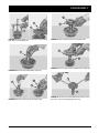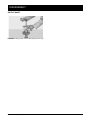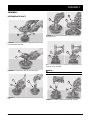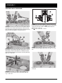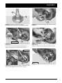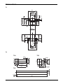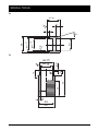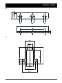
1
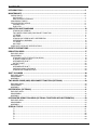
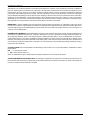
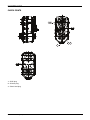
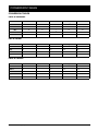
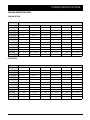
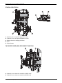
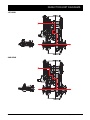
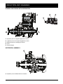
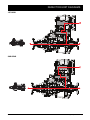
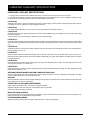
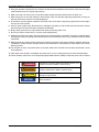
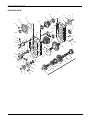
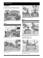
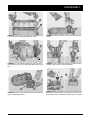
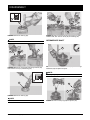
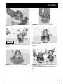
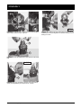
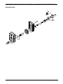
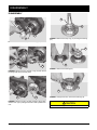
Service Manual Gear Box 360 GSM-0015E January 2014 CONTENTS INTRODUCTION ................................................................................................................................ 5 MAINTENANCE ................................................................................................................................. 6 CHECK POINTS ............................................................................................................................................ 6 DATA PLATE ............................................................................................................................................ 7 MAINTENANCE INTERVALS ................................................................................................................... 7 CONVERSION TABLES ................................................................................................................................ 8 TORQUE SPECIFICATIONS ......................................................................................................................... 9 COARSE PITCH ....................................................................................................................................... 9 FINE PITCH .............................................................................................................................................. 9 REDUCTION UNIT DIAGRAMS ........................................................................................................ 10 STANDALONE VERSION ......................................................................................................................... 10 TWO WHEEL DRIVE (2WD) DISCONNECT FUNCTION .......................................................................... 10 1ST GEAR ................................................................................................................................................ 11 2ND GEAR ............................................................................................................................................... 11 STANDALONE VERSION WITH DIFFERENTIAL ..................................................................................... 12 DIFFERENTIAL ASSEMBLY .................................................................................................................... 12 1ST GEAR ................................................................................................................................................ 13 2ND GEAR ............................................................................................................................................... 13 LUBRICANT & SEALANT SPECIFICATIONS ................................................................................................ 14 SAFETY PRECAUTIONS ................................................................................................................... 15 REDUCTION GEAR ........................................................................................................................... 17 EXPLODED VIEW .......................................................................................................................................... 17 DISASSEMBLY ............................................................................................................................................. 18 STANDARD OUTPUT REDUCTION GEARS ............................................................................................ 18 FLANGED VERSION ONLY ..................................................................................................................... 18 INTERMEDIATE SHAFT ........................................................................................................................... 20 OUTPUT SHAFT ...................................................................................................................................... 22 ASSEMBLY ................................................................................................................................................... 23 INTERMEDIATE SHAFT ........................................................................................................................... 23 CHECKING AXIAL CLEARANCE ............................................................................................................. 24 STANDALONE VERSIONS ONLY ............................................................................................................ 28 SHIFT CYLINDER .............................................................................................................................. 29 EXPLODED VIEW .......................................................................................................................................... 29 DISASSEMBLY ............................................................................................................................................. 30 ASSEMBLY ................................................................................................................................................... 31 TWO WHEEL DRIVE (2WD) DISCONNECT FUNCTION (OPTIONAL) ............................................ 33 EXPLODED VIEW .......................................................................................................................................... 33 DISASSEMBLY ............................................................................................................................................. 34 ASSEMBLY ................................................................................................................................................... 37 DIFFERENTIAL (OPTIONAL) ............................................................................................................ 41 EXPLODED VIEW .......................................................................................................................................... 41 DISASSEMBLY ............................................................................................................................................. 42 ASSEMBLY ................................................................................................................................................... 47 INTEGRATED REDUCTION GEAR (OPTIONAL TOGETHER WITH DIFFERENTIAL) ................... 53 EXPLODED VIEW .......................................................................................................................................... 53 DISASSEMBLY ............................................................................................................................................. 54 ASSEMBLY ................................................................................................................................................... 57 SPECIAL TOOLS ............................................................................................................................... 61 T1 T2 T3 T4 T5 T6 ............................................................................................................................................................. 61 ............................................................................................................................................................. 61 ............................................................................................................................................................. 62 ............................................................................................................................................................. 62 ............................................................................................................................................................. 63 ............................................................................................................................................................. 63 GSM-0015E - 360 Gear Box Service Manual Dana Holding Corporation 3 4 Dana Holding Corporation GSM-0015E - 360 Gear Box Service Manual INTRODUCTION The efficiency and continued operation of mechanical units depend on constant, correct maintenance and also on efficient repair work, should there be a break-down or malfunction. The instructions contained in this manual have been based on a complete overhaul of the unit. However, it is up to the mechanic to decide whether or not it is necessary to assemble only individual components, when partial repair work is needed. The manual provides a quick and sure guide which, with the use of photographs and diagrams illustrating the various phases of the operations, allows accurate work to be performed. All the information needed for correct disassembly, checks and assembly of each individual component is set out below. In order to remove the differential unit from the vehicle, the manuals provided by the vehicle manufacturer should be consulted. In describing the following operations it is presumed that the unit has already been removed from the vehicle. IMPORTANT: In order to facilitate work and protect both working surfaces and operators, it is advisable to use proper equipment such as: trestles or supporting benches, plastic or copper hammers, appropriate levers, pullers and specific spanners or wrenches. Before going on to disassemble the parts and drain the oil, it is best to thoroughly clean the unit, removing any encrusted or accumulated grease. INTRODUCTORY REMARKS: All the disassembled mechanical units should be thoroughly cleaned with appropriate products and restored or replaced if damage, wear, cracking or seizing have occurred. In particular, thoroughly check the condition of all moving parts (bearings, gears, crown wheel and pinion, shafts) and sealing parts (o-rings, oil shields) which are subject to major stress and wear. In any case, it is advisable to replace the seals every time a component is overhauled or repaired. During assembly, the sealing rings must be lubricated on the sealing edge. In the case of the crown wheel and pinion, replacement of one component requires the replacement of the other one. During assembly, the prescribed pre-loading, backlash and torque of parts must be maintained. CLASSIFICATION: This manual classifies units according to part numbers. For a correct interpretation, classification is indicated as follows: = up to the part number = from the part number on When no classification is given, disassembly and assembly operations are the same for all versions. SPECIFIC EQUIPMENT AND SPARE PARTS: The drawings of all specific tools required for maintenance and repair work can be found at the end of this manual; spare parts may be ordered either from the vehicle manufacturer or directly from the Service Centers or Authorized Parts Distributors of DANA. GSM-0015E - 360 Gear Box Service Manual Dana Holding Corporation 5 MAINTENANCE CHECK POINTS 1 3 2 1 3 1 - Oil fill plug 2 - Oil drain plug 3 - Check level plug 6 Dana Holding Corporation GSM-0015E - 360 Gear Box Service Manual CHECK POINTS DATA PLATE R 2 1 3 MFG. BY DANA ITALIA S.P.A. 38062 Arco (Trento) MADE IN ITALY 1 - Model number 2 - Serial number 3 - Lubricant MAINTENANCE INTERVALS OPERATION FREQUENCY Check levels Monthly Oil change Every 1000 hrs * / ** LUBRICANTS ATF DEXRON® III It is recommended to set the oil changes according to the machine maintenance intervals. If working in heavy conditions half intervals should be used. * Initially after 100 working hours ** Clean the sensor contacts at every oil change GSM-0015E - 360 Gear Box Service Manual Dana Holding Corporation 7 CONVERSION TABLES CONVERSION TABLES UNITS OF PRESSURE Atm Atm Bar 1 Bar 1 1 MPa MPa 1 10 10 Pa PSI 0,1 10 5 14,4 0,1 105 14,4 1 106 144 1 - -6 Pa 0,00001 0,00001 PSI - - - - 1 N daN kN kg lbs 10 UNIT OF WEIGHT 1N 1 0,1 0,001 0,102 0,225 1daN 10 1 0,01 1,02 2,25 1kN 1000 100 1 102 225 1kg 9,81 0,981 0,00981 1 2,205 UNITS OF TORQUE N·m daN·m kN·m kg·m lb·in 1N·m 1 0,1 0,001 0,102 8,854 1daN·m 10 1 0,01 1,02 88,54 1kN·m 1000 100 1 102 8854 1kg·m 9,81 0,981 0,00981 1 86,8 1 lb·in 0,1129 0,01129 0,0001129 0,01152 1 8 Dana Holding Corporation GSM-0015E - 360 Gear Box Service Manual TORQUE SPECIFICATIONS TORQUE SPECIFICATIONS COARSE PITCH SIZE OF BOLT TYPE OF BOLT 8.8 8.8 + Loctite 270 10.9 10.9 + Loctite 270 12.9 12.9 + Loctite 270 M6 x 1 mm 9,5 – 10,5 N·m 10,5 – 11,5 N·m 14,3 – 15,7 N·m 15,2 – 16,8 N·m 16,2 – 17,8 N·m 18,1 – 20 N·m M8 x 1,25 mm 23,8 – 26,2 N·m 25,6 – 28,4 N·m 34,2 – 37,8 N·m 36,7 – 40,5 N·m 39 – 43 N·m 43,7 – 48,3 N·m M10 x 1,5 mm 48 – 53 N·m 52 – 58 N·m 68 – 75 N·m 73 – 81 N·m 80 – 88 N·m 88 – 97 N·m M12 x 1,75 mm 82 – 91 N·m 90 – 100 N·m 116 – 128 N·m 126 – 139 N·m 139 – 153 N·m 152 – 168 N·m M14 x 2 mm 129 – 143 N·m 143 – 158 N·m 182 – 202 N·m 200 – 221 N·m 221 – 244 N·m 238 – 263 N·m M16 x 2 mm 200 – 221 N·m 219 – 242 N·m 283 – 312 N·m 309 – 341 N·m 337 – 373 N·m 371 – 410 N·m M18 x 2,5 mm 276 – 305 N·m 299 – 331 N·m 390 – 431 N·m 428 – 473 N·m 466 – 515 N·m 509 – 562 N·m M20 x 2,5 mm 390 – 431 N·m 428 – 473 N·m 553 – 611 N·m 603 – 667 N·m 660 – 730 N·m 722 – 798 N·m M22 x 2,5 mm 523 – 578 N·m 575 – 635 N·m 746 – 824 N·m 817 – 903 N·m 893 – 987 N·m 974 – 1076 N·m M24 x 3 mm 675 – 746 N·m 732 – 809 N·m 950 – 1050 N·m 1040 – 1150 N·m 1140 – 1260 N·m 1240 – 1370 N·m M27 x 3 mm 998 – 1103 N·m 1088 – 1202 N·m 1411 – 1559 N·m 1539 – 1701 N·m 1710 – 1890 N·m 1838 – 2032 N·m M30 x 3,5 mm 1378 – 1523 N·m 1473 – 1628 N·m 1914 – 2115 N·m 2085 – 2305 N·m 2280 – 2520 N·m 2494 – 2757 N·m FINE PITCH SIZE OF BOLT TYPE OF BOLT 8.8 8.8 + Loctite 270 10.9 10.9 + Loctite 270 12.9 12.9 + Loctite 270 M8 x 1 mm 25,7 – 28,3 N·m 27,5 – 30,5 N·m 36,2 – 39,8 N·m 40 – 44 N·m 42,8 – 47,2 N·m 47,5 – 52,5 N·m M10 x 1,25 mm 49,4 – 54,6 N·m 55,2 – 61 N·m 71,5 – 78,5 N·m 78 – 86 N·m 86 – 94 N·m 93 – 103 N·m M12 x 1,25 mm 90 – 100 N·m 98 – 109 N·m 128 – 142 N·m 139 – 154 N·m 152 – 168 N·m 166 – 184 N·m M12 x 1,5 mm 86 – 95 N·m 94 – 104 N·m 120 – 132 N·m 133 – 147 N·m 143 – 158 N·m 159 – 175 N·m M14 x 1,5 mm 143 – 158 N·m 157 – 173 N·m 200 – 222 N·m 219 – 242 N·m 238 – 263 N·m 261 – 289 N·m M16 x 1,5 mm 214 – 236 N·m 233 – 257 N·m 302 – 334 N·m 333 – 368 N·m 361 – 399 N·m 394 – 436 N·m M18 x 1,5 mm 312 – 345 N·m 342 – 378 N·m 442 – 489 N·m 485 – 536 N·m 527 – 583 N·m 580 – 641 N·m M20 x 1,5 mm 437 – 483 N·m 475 – 525 N·m 613 – 677 N·m 674 – 745 N·m 736 – 814 N·m 808 – 893 N·m M22 x 1,5 mm 581 – 642 N·m 637 – 704 N·m 822 – 908 N·m 903 – 998 N·m 998 – 1103 N·m 1078 – 1191 N·m M24 x 2 mm 741 – 819 N·m 808 – 893 N·m 1045 – 1155 N·m 1140 – 1260 N·m 1235 – 1365 N·m 1363 – 1507 N·m M27 x 2 mm 1083 – 1197 N·m 1178 – 1302 N·m 1520 – 1680 N·m 1672 – 1848 N·m 1834 – 2027 N·m 2000 – 2210 N·m M30 x 2 mm 1511 – 1670 N·m 1648 – 1822 N·m 2138 – 2363 N·m 2332 – 2577 N·m 2565 – 2835 N·m 2788 – 3082 N·m GSM-0015E - 360 Gear Box Service Manual Dana Holding Corporation 9 REDUCTION UNIT DIAGRAMS REDU CTION UN IT D IAGRAMS STANDALONE VERSION A D B C E E A - Hydraulic port for 1st gear engagement control B - Hydraulic port for 2nd gear engagement control C - Manual control for changing to neutral D - Drive E - Output flanges TWO WHEEL DRIVE (2WD) DISCONNECT FUNCTION A B A - Hydraulic port to detect four-wheel drive (4WD) mode B - Hydraulic port to detect two-wheel drive (2WD) mode 10 Dana Holding Corporation GSM-0015E - 360 Gear Box Service Manual REDUCTION UNIT DIAGRAMS 1ST GEAR 2ND GEAR GSM-0015E - 360 Gear Box Service Manual Dana Holding Corporation 11 REDUCTION UNIT DIAGRAMS STANDALONE VERSION WITH DIFFERENTIAL A D B C E E A - Hydraulic port for 1st gear engagement control B - Hydraulic port for 2nd gear engagement control C - Manual control for changing to neutral D - Drive E - Output flanges DIFFERENTIAL ASSEMBLY A A - Hydraulic port for differential lock actuation 12 Dana Holding Corporation GSM-0015E - 360 Gear Box Service Manual REDUCTION UNIT DIAGRAMS 1ST GEAR 2ND GEAR GSM-0015E - 360 Gear Box Service Manual Dana Holding Corporation 13 LUBRICANT & SEALANT SPECIFICATIONS LUBRICANT & SEALANT SPECIFICATIONS 1 - Locking, sealing and lubricating materials referred to in this manual are the same used in the shop-floor. 2 - The table below gives an account of the typical applications of each single material, in order to facilitate replacement with similar products marketed by different brand names with different trade marks. LOCTITE 242 Anaerobic product apt to prevent the loosening of screws, nuts and plugs. Used for medium-strength locking. Before using it, completely remove any lubricant by using the specific activator. LOCTITE 243 The oleocompatible alternative to 242. Does not require the activation of lubricated surfaces. LOCTITE 270 Anaerobic product for very-high strength locking of screws and nuts. Before using it, completely remove any lubricant by using the specific activator. To remove parts, it may be necessary to heat them at 80 °C approximately. LOCTITE 275 Anaerobic product suitable for high-strength locking and sealing of large threaded parts, bolts and stud bolts, for pipe sealing and for protecting parts against tampering; suitable for sealing coupling surfaces with a maximum diametrical clearance of 0.25 mm. LOCTITE 510 Anaerobic product for the hermetic sealing of flanged units and screw holes communicating with fluids. Can seal clearances between flanges up to 0.2 mm. LOCTITE 577 Quick anaerobic sealant for sealing threaded portions of conical or cylindrical unions up to M80. Before using it, remove any lubricant with the specific activator. After polymerisation, disassembly may result rather difficult, so heating may be necessary for larger diameters. LOCTITE 638 Anaerobic adhesive for fast and high-strength gluing of cylindrical metal joints (hub on shaft). Can glue together parts with clearance ranging between 0.1 and 0.25 mm. LOCTITE 648 Anaerobic adhesive for fast and medium-strength gluing of cylindrical metal joints (hub on shaft). Can glue together parts with radial clearance below 0.1 mm. AREXONS (REPOSITIONABLE JOINTING COMPOUND FOR SEALS) Solvent-based sealing compound for elastic seals, drying through evaporation. Used for sealing the outer diameter of sealing rings for rotating shafts with outer metal reinforcement. SILICONE Semi-fluid adhesive material used for sealing and filling and to protect components from environmental and physical elements. Polymerises with non-corrosive dampness. TECNO LUBE/101 (SILICONE-BASED GREASE) Highly adhesive synthetic grease, with silicone compounds added. Applied to adjustment screws with hole communicating with oil-type fluids. Used when frequent adjusting is required. MOLIKOTE (DOW CORNING) Lubricating compound containing molybdenum disulphide, used to lubricate articulation pins and to prevent sticking and oxidation of parts that are not lubricated on a regular basis. (LITHIUM-BASED) GREASE Applied to bearings, sliding parts and used to lubricate seals or parts during assembly. 14 Dana Holding Corporation GSM-0015E - 360 Gear Box Service Manual SAFETY PRECAUTIONS 1. During all operations described in this manual, the axle should be fastened onto a trestle, while the other parts mentioned should rest on supporting benches. 2. When removing one of the arms, an anti-tilting safety trestle should be placed under the other arm. 3. When working on an arm that is fitted on the machine, make sure that the supporting trestles are correctly po- sitioned and that the machine is locked lengthways. 4. Do not admit any other person inside the work area; mark off the area, hang warning signs and remove the igni- tion key from the machine. 5. Use only clean, quality tools; discard all worn, damaged, lowquality or improvised wrenches and tools. Ensure that all torque wrenches have been checked and calibrated. 6. Always wear gloves and non-slip rubber shoes when performing repair work. 7. Should you stain a surface with oil, remove marks straight away. 8. Dispose of all lubricants, seals, rags and solvents once work has been completed. Treat them as special waste and dispose of them according to the relative law provisions obtaining in the country where the axles are being overhauled. 9. Make sure that only weak solvents are used for cleaning purposes; avoid using turpentine, dilutants and toluol, xylolbased or similar solvents; use light solvents such as Kerosene, mineral spirits or water-based, environment friendly solvents. 10. For the sake of clarity, the parts that do not normally need to be removed have not been reproduced in some of the diagrams. 11. After repair work has been completed, accurately touch up any coated part that may have been damaged. 12. Follow all safety instructions in the Original Equipment Manufacturer (OEM) manual that came with the vehicle. DANGER Indicates an imminently hazardous situation which, if not avoided, will result in death or serious injury. WARNING Indicates an imminently hazardous situation which, if not avoided, could result in death or serious injury. CAUTION Indicates a situation which, if not avoided, may result in damage to components. NOTICE Indicates information which may make product service easier to perform. GSM-0015E - 360 Gear Box Service Manual Dana Holding Corporation 15 LUBRICANT & SEALANT SPECIFICATIONS 16 Dana Holding Corporation GSM-0015E - 360 Gear Box Service Manual REDUCTION GEAR EXPLODED VIEW 24 25 53 28 15 18 14 13 16 26 27 51 19 23 52 54 3 8 7 5 9 17 50 4 55 36 6 38 35 39 34 57 20 22 1 33 21 47 32 2 37 10 31 11 12 56 30 29 GSM-0015E - 360 Gear Box Service Manual 40 41 42 43 44 46 48 49 45 22 Dana Holding Corporation 17 DISASSEMBLY DISASSEMBLY STANDARD OUTPUT REDUCTION GEARS 12 2 10 11 1 FIGURE 4: Remove fastening nut from output flange (10), then remove o-ring (11) and flange (12). NOTE: FIGURE 1: Remove the screw (1) and speed sensor (2) with o-ring (57). If second flange is provided, remove using the same method. NOTE: Note direction of reference notch installation. 15 4 16 13 14 3 3 5 FIGURE 5: Overturn the reduction gear and position it on two blocks. Loosen and remove screws (13), spring washers (14), cover (15), and shims (16), if applicable. Also remove capscrews (55) and washers (56). FIGURE 2: Remove the position sensor (3) together with oring (4) and retaining ring (5). 6 FLANGED VERSION ONLY 17 7 9 8 FIGURE 3: Remove the gearshift cylinder assembly (6), snap ring (7), piston (8), and guide bushing (9). For details, see SHIFT CYLINDER p. 29. 18 Dana Holding Corporation FIGURE 6: Remove the outermost stud (17) using the nut and lock nut method. Tighten two long-shank eyebolts respectively in the stud hole and flange hole. Connect eyebolts to a hoist and tighten the chains. GSM-0015E - 360 Gear Box Service Manual DISASSEMBLY 18 19 24 FIGURE 7: Remove cover (18) by striking with a plastic hammer. Remove the centering bushings (19) as well. FIGURE 10: Using an extractor, remove non-input side bearing (24). 20 26 25 25 21 20 FIGURE 8: Turn the reduction gear to one side and, with a plastic hammer, remove the output shaft (20) and flow guard (21). FIGURE 11: Remove the input shaft (25) complete with bearing (26). Using a puller, remove bearing (26). 53 28 27 52 23 22 FIGURE 9: Remove the intermediate shaft (22) complete with gears and gearshift fork (23). GSM-0015E - 360 Gear Box Service Manual FIGURE 12: Mark the position between the hydrostatic motor flange (28) and reduction gear cover (52). Remove screws (27) and the hydrostatic cover flange (28). Remove the o-ring (53). Dana Holding Corporation 19 DISASSEMBLY 34 54 33 54 35 36 FIGURE 16: Remove screws (33) and cover (34) from intermediate shaft; then remove shims (35) and bearing (36). FIGURE 13: Remove seal ring (54). NOTE: INTERMEDIATE SHAFT Note direction of installation. 23 32 37 29 30 22 31 FIGURE 14: Remove screws (29) and spring washers (30); then remove cover (31) and bearing (32). FIGURE 17: From the intermediate shaft (22), remove the gearshift fork (23) complete with pads. NOTE: Carefully inspect pads for wear. 37 37 38 39 FIGURE 15: Remove seal ring (37). NOTE: Note direction of installation. 20 Dana Holding Corporation FIGURE 18: Remove snap ring (38) and spacer (39). GSM-0015E - 360 Gear Box Service Manual DISASSEMBLY 46 40 45 41 36 FIGURE 19: Using a puller, remove the inner ring of bearing (36), spacer (40), and gear (41). FIGURE 22: Remove sleeve yoke (45) and sleeve (46). 47 42 48 FIGURE 23: Remove gear (47) and needle bearing cages (48). FIGURE 20: Remove the needle bearing cage (42). 43 43 50 44 49 FIGURE 21: Remove snap ring (43) and spacer (44). GSM-0015E - 360 Gear Box Service Manual FIGURE 24: Overturn the intermediate shaft (49) and, using two levers, remove the bearing (50) inner ring. Dana Holding Corporation 21 DISASSEMBLY OUTPUT SHAFT 51 FIGURE 25: Using a puller, remove the bearing (51) inner ring. 22 Dana Holding Corporation GSM-0015E - 360 Gear Box Service Manual ASSEMBLY ASSEMBLY 40 INTERMEDIATE SHAFT 42 41 47 48 49 FIGURE 29: Install the needle bearing cage (42), gear (41), and spacer (40). FIGURE 26: Install needle bearing cages (48) and gear (47) to the intermediate shaft (49). 46 36 49 49 45 50 FIGURE 30: Using an appropriate driver, install bearing inner rings (36, 50) to shaft (49). FIGURE 27: Install sleeve yoke (45) and sleeve (46). NOTE: Check direction of installation carefully. 43 43 38 44 38 39 FIGURE 28: Install in sequence the spacer (44) and snap ring (43). GSM-0015E - 360 Gear Box Service Manual FIGURE 31: Install the spacer (39) and snap ring (38). Dana Holding Corporation 23 ASSEMBLY CHECKING AXIAL CLEARANCE 35 34 S 34 52 36 FIGURE 32: Introduce only part of the intermediate shaft bearing (36) in the reduction gear body (52). Center the cover (34) on the bearing and fasten (temporarily and without shims) with the screws and tighten to a torque of 50 N·m. FIGURE 35: Calculate the difference between the two measures to determine the thickness "S" of shims to be inserted under the cover (34) to obtain the prescribed clearance between 0.25 - 0.45 mm. E.g.: S= (Y-X) = 86,1-85,2 = 0,9 mm. 34 50 A 35 52 36 22 X FIGURE 33: Overturn the reduction gear body (52) and insert the complete intermediate shaft (22). Using a bar "A" and a depth gauge, measure the distance "X" between the inner ring of bearing (50) and the surface of the reduction gear body (52). e.g.: X = 85,2 mm. FIGURE 36: Assemble an appropriate pack of shims (35) choosing among available shims. E.g.: (S x 0.5) + 0,1 = 0.5 mm. 34 A Y FIGURE 37: Remove intermediate shaft assembly (22) and cover (34). FIGURE 34: Using bar "A" again, measure distance "Y" between the cover surface (18) and the bearing (50) face. e.g.: Y = 86.1 mm. 24 Dana Holding Corporation GSM-0015E - 360 Gear Box Service Manual ASSEMBLY 33 32 FIGURE 38: Apply grease to shims (35) and position them in the cover (34). Apply Loctite 510 to cover face (34). Center shims (35) and bearing (36). Install cover (34) with screws (33) coated with Loctite 510 and tighten to a torque of 50 N·m. FIGURE 41: Using a plastic hammer, install bearing (32). 37 54 31 28 FIGURE 42: Using an appropriate driver, install the new seal ring (37) to cover (31). FIGURE 39: Using an appropriate driver, install the new seal ring (54) to hydrostatic motor flange (28). NOTE: Lubricate the outer surface with oil. Check direction of installation carefully. NOTE: Lubricate the outer surface with oil. Check direction of installation carefully. 31 28 27 29 30 FIGURE 40: Fit the hydrostatic motor flange (28) complete with new o-ring (53) and attach it with screws (27) coated with Loctite 510. Tighten the screws using the criss-cross method to a torque of 50 N·m. GSM-0015E - 360 Gear Box Service Manual FIGURE 43: Coat cover face (31) with Loctite 510 and install with screws (29) and spring washers (30) then tighten to 50 N·m using the criss-cross method. Dana Holding Corporation 25 ASSEMBLY 26 20 25 51 FIGURE 44: Heat bearing (26) to about 194°F [90°C] and install to input shaft (25). FIGURE 47: Using an appropriate driver, install bearing (51) inner ring to output shaft (20). NOTE: Make sure bearing rests properly against shaft. 21 25 52 FIGURE 48: Position the flow guard (21) and ensure it is properly engaged in its seat. FIGURE 45: Using a plastic hammer, install input shaft (25) in reduction gear case (52). 20 22 23 52 52 45 FIGURE 49: Fit the output shaft (20) in the reduction gear body (52) and engage shaft by hitting with a plastic hammer. FIGURE 46: Fit gearshift fork (23) to sleeve yoke (45) and install the complete intermediate shaft (22) in reduction gear case (52). 26 Dana Holding Corporation GSM-0015E - 360 Gear Box Service Manual ASSEMBLY A 18 19 FIGURE 53: Measure the quote “A” as shown in figure. Example: A = 1 mm 21 19 B FIGURE 50: Insert guide bushings (19) and apply Loctite 510 to the coupling surface of the casing. Check position of guard (21) and fit cover (18). 17 18 55 56 FIGURE 51: Attach cover (18) with screws (55) and spring washers (56). Tighten all screws (55) and then torque to 50 N·m using the criss-cross method. Start tightening with central screws. Apply Loctite 510 to the previously removed stud (17) and attach in the cover (18). 24 FIGURE 54: Measure the quote “B” between reductor case (18) and bearing (24). Calculate the shims “S” (16) using the following formula: S = (A - B) - G Where “G” is the predifined gap = 0,15 - 0,35 mm Example: A = 1 mm B = 0,5 mm S = (1 - 0,5) - 0,2 = 0,3 mm S = 0,3 mm 15 13 14 18 FIGURE 55: Apply Loctite 510 to cover (15) and screw (13) threads. Then install spring washers (14) and screws (13) to attach cover (15). Tighten screws to a torque of 50 N·m using the criss-cross method. FIGURE 52: Using an appropriate driver, fit the bearing (24) in the cover (18). GSM-0015E - 360 Gear Box Service Manual Dana Holding Corporation 27 ASSEMBLY STANDALONE VERSIONS ONLY 4 3 3 5 29 15 30 FIGURE 56: Apply Loctite 510 to the face of the second output cover (15), and then fasten with screws (29) and spring washers (30) to a torque of 50 N·m using the criss-cross method. FIGURE 59: Install the position sensor (3) together with o-ring (4) and retaining ring (5). 2 12 B 12 57 10 11 FIGURE 60: Check o-ring (57) for damage and install the speed sensor (2). FIGURE 57: Install o-ring (11) and nut (10), coated with Loctite 242. Install output flange (12) and tighten nut to a torque of 260 - 300 N·m. CAUTION The triangular reference notch "B" must be oriented in the direction of movement of gear teeth. NOTE: Install second flange, using the same procedure. 1 6 FIGURE 61: Lock speed sensor (2) into position tightening the screw (1) to 8 - 10 N·m. FIGURE 58: Install the gearshift cylinder assembly (6) including snap ring (7), piston (8), and guide bushing (9). For additional details, see SHIFT CYLINDER p. 29. 28 Dana Holding Corporation GSM-0015E - 360 Gear Box Service Manual SHIFT CYLINDER EXPLODED VIEW 13 1 9 3 4 6 5 12 2 10 13 GSM-0015E - 360 Gear Box Service Manual 11 8 7 Dana Holding Corporation 29 DISASSEMBLY DISASSEMBLY 9 2 1 1 3 FIGURE 4: Remove complete cylinder (9). NOTE: FIGURE 1: Remove position sensor (1) together with o-ring (2) and retaining ring (3). To remove cylinder, use a plastic hammer. Remove any sealant residue from reduction gear and cylinder surface. 11 10 6 5 4 12 FIGURE 2: Remove dowel (4), spring (5), and ball (6). FIGURE 5: Remove snap ring (10) and pull out whole piston (11) and guide bushing (12). NOTE: Seals must be replaced at each disassembly. 13 7 8 FIGURE 3: Extract screws (7) and spring washers (8). FIGURE 6: Using a screwdriver, remove the dust scraper ring (13). NOTE: The ring must be replaced at each disassembly. 30 Dana Holding Corporation GSM-0015E - 360 Gear Box Service Manual ASSEMBLY ASSEMBLY 9 11 12 13 7 8 FIGURE 7: Replace seals (13) on piston (11), guide bushing (12) and cylinder (9). FIGURE 10: Apply the Loctite 510 to the surface of the cylinder and the screw (7). Install cylinder to reduction gear with screws (7) and washers (8) tightening to a torque of 50 N·m. 9 11 6 5 10 12 FIGURE 8: Lubricate o-rings (13) with oil and install in sequence bushing (12), piston (11), and snap ring (10). 4 FIGURE 11: Install the ball (6), spring (5), and dowel (4) coated with Loctite 242, in the cylinder (9). Tighten dowel so it is flush with the cylinder. 2 1 1 3 13 FIGURE 9: Using a suitable driver, install the new dust scraper ring (13) in the cylinder. GSM-0015E - 360 Gear Box Service Manual FIGURE 12: Install position sensor (1) together with o-ring (2) and retaining ring (3). Tighten to a maximum torque of 54.2 N·m. Dana Holding Corporation 31 ASSEMBLY 32 Dana Holding Corporation GSM-0015E - 360 Gear Box Service Manual TWO WHEEL DRIVE (2WD) DISCONNECT FUNCTION (OPTIONAL) EXPLODED VIEW 6 18 17 7 16 9 12 11 14 13 15 10 19 23 6 8 20 22 21 24 25 5 29 28 27 30 1 2 3 4 32 26 31 25 30 26 31 27 6 5 23 4 3 2 24 21 29 28 20 32 GSM-0015E - 360 Gear Box Service Manual Dana Holding Corporation 33 DISASSEMBLY DISASSEMBLY 14 13 15 6 FIGURE 4: Remove piston (13) complete with o-rings (14, 15). NOTE: FIGURE 1: Remove the microswitch (6) coupling. O-rings must be replaced at each disassembly. 1 7 8 2 3 FIGURE 2: Loosen and remove screws (7) and washers, then remove cylinder assembly (8). FIGURE 5: Remove nut (1), o-ring (2), and flange (3). NOTE: To remove, introduce a lever between cylinder and shaft support. 32 11 9 10 12 FIGURE 6: Loosen and remove check screws (32) and the releasable shaft assembly support (5). NOTE: FIGURE 3: Center fork (10) stop pin (9) in relation to the microswitch hole, then remove the pin using a pin-driver. Loosen and remove the screws (11) and cover (12). 34 Dana Holding Corporation To assist with removal, use a plastic hammer. GSM-0015E - 360 Gear Box Service Manual DISASSEMBLY 22 19 20 25 FIGURE 7: Remove the needle bearing cage (20) from the reduction gear body pinion (19). FIGURE 10: Remove the complete coupling assembly (25) using a plastic hammer. 23 21 26 22 FIGURE 8: Mark the position of flange (21) in relation to the reduction gear body (22). Loosen and remove screws (23) and flange (21). FIGURE 11: Remove the sleeve (26) from the coupling assembly. NOTE: To loosen flange, use a plastic hammer. 27 31 26 30 24 FIGURE 12: Take the coupling assembly apart by removing the bushing (27) and detent balls (30) from the coupling shaft (31). FIGURE 9: Only if reduction gear needs removing: Remove the snap ring (24). GSM-0015E - 360 Gear Box Service Manual Dana Holding Corporation 35 DISASSEMBLY 4 FIGURE 13: Remove the seal ring (4). NOTE: Note down the direction of installation. Replace ring at each disassembly. 29 5 28 FIGURE 14: Remove snap ring (28) from support (5) and, using an appropriate driver, remove the bearing (29). 36 Dana Holding Corporation GSM-0015E - 360 Gear Box Service Manual ASSEMBLY ASSEMBLY 25 29 5 5 29 28 FIGURE 15: Using an appropriate driver, fit the bearing (29) in the support (5) and install snap ring (28). FIGURE 18: Introduce the entire coupling assembly (25) in the support (5) and make it rest against the bearing (29). NOTE: If necessary, use a plastic hammer. 4 5 24 FIGURE 16: Using an appropriate driver, fit the seal ring (4) in the support (5). FIGURE 19: Only if previously removed: Install the snap ring (24). NOTE: Check direction of installation carefully Introduce ring so it is recessed by 1 mm in relation to the surface of the support. 31 22 21 26 27 30 FIGURE 20: Apply Loctite 510 to the surface of reduction gear (22). Install the flange (21) and position it so the marks made during disassembly match up. FIGURE 17: Install the coupling assembly (25) complete with sleeve (26) and bushing (27). NOTE: To hold detent balls (30) in their seats, fill the slots in the coupling shaft (31) with grease. GSM-0015E - 360 Gear Box Service Manual Dana Holding Corporation 37 ASSEMBLY 15 14 13 21 23 FIGURE 21: Attach the flange (21) using screws (23) coated with Loctite 510 using the criss-cross method to a torque of 86 - 89 N·m. 10 16 FIGURE 24: Fit new o-rings (14, 15) onto the piston (13) and lubricate both seal and piston (13) with oil. Introduce piston (13) into cylinder (8) and fork (10); install o-ring (15) and piston (13) fully. 19 11 9 10 13 12 20 FIGURE 22: Grease and insert needle bearing cage (20) in pinion (19). FIGURE 25: Fasten piston (13) and fork (10) with spring pin (9). Apply Loctite 510 to the surface of the cylinder. Fit the cover (12) and secure with screws (11) tightening to a 25 - 26 N·m. 21 7 5 25 32 FIGURE 23: Apply Loctite 510 to the surface of the flange (21) and install the complete support assembly (5). Lock with screws (32) coated with Loctite 510, and tighten using the criss-cross method to a torque of 49 - 51 N·m. 38 Dana Holding Corporation 8 FIGURE 26: Apply Loctite 510 to the surface for the piston assembly (8). Install the piston assembly (8) by centering the reference pins and fasten with screws (7) to a torque of 25 26 N·m. GSM-0015E - 360 Gear Box Service Manual ASSEMBLY 2 3 FIGURE 27: Install flange (3), o-ring (2), and apply Loctite 242 to the threaded portion of the coupling shaft assembly (25). Apply an appropriate counter wrench to the flange and tighten nut to a torque of 260 - 280 N·m. 17 6 18 FIGURE 28: Install coupling sensor (6) complete with o-ring (17) and retaining ring (18) and tighten to a torque of 54 N·m. GSM-0015E - 360 Gear Box Service Manual Dana Holding Corporation 39 ASSEMBLY 40 Dana Holding Corporation GSM-0015E - 360 Gear Box Service Manual DIFFERENTIAL (OPTIONAL) EXPLODED VIEW 40 39 38 46 37 32 34 33 35 31 36 29 30 25 28 9 10 8 24 4 7 5 3 6 26 27 2 1 44 42 43 14 22 15 13 16 14 19 15 17 18 12 13 4 20 12 11 3 21 13 15 14 17 20 43 16 13 15 23 GSM-0015E - 360 Gear Box Service Manual 14 Dana Holding Corporation 41 DISASSEMBLY DISASSEMBLY 5 3 4 FIGURE 4: Disconnect selector (36) from piston (30). While holding the selector up, remove the differential unit. FIGURE 1: Loosen and remove the screws (3) and washers (4). Remove the differential unit cover (5). 36 39 FIGURE 5: Extract selector (36) from the coupling (25). FIGURE 2: Remove the security switch (39) complete with seal washers (37, 38, 46). 35 8 30 FIGURE 6: Using an extractor, remove the bearing (8). FIGURE 3: Using two wrenches, lock piston (30) and remove nut (35). 42 Dana Holding Corporation GSM-0015E - 360 Gear Box Service Manual DISASSEMBLY 25 14 23 FIGURE 7: Remove the coupling (25) and the spheres (23). 10 13 FIGURE 10: Remove the snap rings (14) from the two pins (13) of the satellite gears (17). T1 4 T1 17 17 FIGURE 8: ONLY IF NECESSARY Remove the key (10). 21 FIGURE 11: Insert tool T1 (See drawing T1 p. 61) between the satellite gears (17). 19 11 13 FIGURE 9: Loosen and remove the cover (19) screws (21). Remove the 1st planetary side gear (12) and thrust washer (16). GSM-0015E - 360 Gear Box Service Manual FIGURE 12: Force tool T1 (See drawing T1 p. 61) in-between the satellite gears (17) using two pin-drivers. Dana Holding Corporation 43 DISASSEMBLY T16B T2B T3 T1 5 T1 4 T1 17 T16B T2B 13 11 FIGURE 13: Place the differential carrier (11) under a press, position guide bushing T3 (See drawing T3 p. 62) and insert press tool T2A (See drawing T2 p. 61). Press T2A (See drawing T2 p. 61) pin to limit position. NOTE: 17 FIGURE 16: Leave the released satellite gear (17) in position and again lock tool T1 (See drawing T1 p. 61). Repeat the operations for the extraction of the pin of the 2nd satellite gear (17) and thrust washer (16). Repeat the operations for all other pins. This operation will release the snap ring (15) from the pins (13). 12 T35 T1 T2A T16A 20 6 11 FIGURE 14: Remove press tool T2A (See drawing T2 p. 61) and guide bushing T3 (See drawing T3 p. 62). FIGURE 17: Remove tool T1 (See drawing T1 p. 61) and remove the last two satellite gears (17), thrust washer (16), the 2nd planetary side gear (12), and the relative shim washer (20) from the differential carrier. Using an extractor for inner parts, remove the bushing (9). NOTE: In this photo the tool T1 (See drawing T1 p. 61) contains pin (13). 34 30 11 FIGURE 18: Remove snap ring (34) and complete piston (30). FIGURE 15: Remove tool T1 (See drawing T1 p. 61) together with the pin (13) of the satellite gear and snap rings (15). 44 Dana Holding Corporation GSM-0015E - 360 Gear Box Service Manual DISASSEMBLY 31 42 33 32 1 2 30 FIGURE 19: Remove snap ring (31) and take piston unit (30) apart. Remove all component parts (32, 33). FIGURE 22: Remove the nut (1) and o-ring (2) and pull out the flange (42) with protection plate. 5 26 28 29 FIGURE 20: Remove guide ring (28) and o-ring (29). FIGURE 23: Remove the lower shaft (26). NOTE: The guide ring (28) and o-ring (29) must be replaced each time the unit is disassembled. 7 5 27 5 1 FIGURE 24: Remove the snap ring (7) securing the bearing (27). Remove the bearing (27). FIGURE 21: Loosen the nut (1) from the flange (42). GSM-0015E - 360 Gear Box Service Manual Dana Holding Corporation 45 DISASSEMBLY 6 5 FIGURE 25: Using two levers, remove the seal ring (6). CAUTION Be sure not to damage the sealing surfaces. 22 FIGURE 26: Remove the screws (5) and washers (4) attaching the cover (22). Strike a few times with a plastic hammer to loosen the cover (22). NOTE: Write down the order of assembly. 46 Dana Holding Corporation GSM-0015E - 360 Gear Box Service Manual ASSEMBLY ASSEMBLY 48 - 53 N·m 27 22 FIGURE 27: Coat the machined contact surface of the main body with Loctite 510 and install the support (22). Secure with screws (3) and washers (4) and tightening to a torque of 48 - 53 N·m. 5 7 FIGURE 29: Insert the bearing (27) and secure with the snap ring (7). Carefully check the snap ring (7) is completely inserted. NOTE: Make sure a continuous layer of sealant runs around the locking holes. 26 T6 FIGURE 30: Install the output shaft (26). 6 FIGURE 28: Grease the inner edge of the seal ring (6). Using the special tool T6 (See drawing T6 p. 63), install the seal ring (6) in the cover (5). 42 CAUTION Pay particular attention to the direction of assembly of the rings (6). GSM-0015E - 360 Gear Box Service Manual FIGURE 31: Fit the flange (42) on the shaft (26), seating completely. Dana Holding Corporation 47 ASSEMBLY T4 30 1 2 FIGURE 32: Lubricate the o-ring (2) with grease and fit in the flange (42) seating. Coat the nut (1) with Loctite 270 and install. FIGURE 35: Insert tool T4 (See drawing T4 p. 62) in the central unit (5) and push the piston (30) into the seat. Remove tool T4 (See drawing T4 p. 62). 33 32 30 35 - 50 N·m FIGURE 33: Tighten the nut (1) to a torque of 35 - 50 N·m. FIGURE 36: Install spring (32) and washer (33) on the piston (30). 30 T5 29 28 FIGURE 34: Fit o-ring (29) and guide ring (28) onto the piston (30). 48 Dana Holding Corporation FIGURE 37: Install tool T5 (See drawing T5 p. 63) on the thread of the piston (30) to compress the spring (32) and open the seat for installing the snap ring (34). GSM-0015E - 360 Gear Box Service Manual ASSEMBLY 17 16 T2C T16C 34 FIGURE 38: Install the snap ring (34). Remove tool T5 (See drawing T5 p. 63). FIGURE 41: Position the thrust washer (16) and the first satellite gear (17). Hold them in position using bar T2C (See drawing T2 p. 61). 31 17 T16A T2A 11 16 T2C T16C FIGURE 39: Install the snap ring (31). FIGURE 42: Using press tool T2A (See drawing T2 p. 61), position the second satellite gear (17) and thrust washer (16). 12 T1 4 T1 20 6 11 T16C T2C FIGURE 40: Lubricate and seat the bushing (9). Insert the shim (20) and the differential side gear (12) in the differential carrier (11). GSM-0015E - 360 Gear Box Service Manual FIGURE 43: Insert tool T1 (See drawing T1 p. 61) between the two satellite gears (17). Line up the entire unit by pushing bar T2C (See drawing T2 p. 61) all the way down until press tool T2A (See drawing T2 p. 61) is ejected. Dana Holding Corporation 49 ASSEMBLY T16B T2B T14 T1 T35 T1 T2B T16B 17 17 FIGURE 44: Lock tool T1 (See drawing T1 p. 61) behind the satellite gears (17). After locking, remove bar T2C (See drawing T2 p. 61). 13 FIGURE 47: Put press tool T2B (See drawing T2 p. 61) on top of the planetary wheel pin (13). T16B T2B 15 13 13 T3 T1 5 T16B T2B 13 11 FIGURE 45: Fit the snap rings (15) onto the pins (13). 13 FIGURE 48: Press T2B (See drawing T2 p. 61) pin all the way down. T1 T35 14 11 FIGURE 46: Place the differential carrier (11) under the press, position guide bushing T3 (See drawing T3 p. 62) and insert the planetary pin (13). 13 FIGURE 49: Remove press tool T2B (See drawing T2 p. 61), bushing T3 (See drawing T3 p. 62) and fit the snap ring (14) on the pin (13). CAUTION Make sure the snap ring centers in the seat and that it rests on the surface of the differential carrier. Repeat the operations on the other planetary pins. 50 Dana Holding Corporation GSM-0015E - 360 Gear Box Service Manual ASSEMBLY 12 25 23 11 FIGURE 50: Position the second planetary gear (12) in the differential carrier (11). FIGURE 53: Install spheres (23), and sleeve (25). 19 8 21 Loctite 242 139 - 154 N·m FIGURE 51: Install spacer (18) and the cover (19), secure in position with the screws (21) and tighten to a torque of 139 154 N·m. FIGURE 54: Heat the bearing (8) to a temperature of approximately 230°F [110°C]. Fit onto differential housing, ensuring the bearing (8) is seated completely. 10 11 30 36 5 FIGURE 52: ONLY IF PREVIOUSLY DISASSEMBLED Position the key (10) in the differential unit (11). GSM-0015E - 360 Gear Box Service Manual FIGURE 55: Insert the selector (36) and the differential unit (11) into the central unit (5). Engage the fork (36) in the coupling (25) and on the piston (30). Dana Holding Corporation 51 ASSEMBLY 35 30 39 15 N·m FIGURE 56: Install the lock nut (35) of the fork (36) and tighten with a torque wrench to 90 - 100 N·m. FIGURE 59: Install the security switch (39) complete with seal washers (37, 38, 46) and tighten to a maximum torque wrench setting of 15 N·m. 5 22 FIGURE 57: Insert the differential unit (5) into the central unit (22). 48 - 53 N·m 3 4 FIGURE 58: Secure in position with the screws (3) and washers (4) and tightening to a torque of 48 - 53 N·m. 52 Dana Holding Corporation GSM-0015E - 360 Gear Box Service Manual INTEGRATED REDUCTION GEAR (OPTIONAL TOGETHER WITH DIFFERENTIAL) EXPLODED VIEW 20 19 17 21 13 22 14 15 18 16 12 11 10 9 8 7 6 5 3 1 4 2 GSM-0015E - 360 Gear Box Service Manual Dana Holding Corporation 53 DISASSEMBLY DISASSEMBLY 11 14 18 FIGURE 4: Remove the snap ring (11) securing the bearing (12). 19 FIGURE 1: Loosen the nut (18) from the flange (19). 12 17 14 19 18 FIGURE 5: Remove the bearing (12). FIGURE 2: Remove the nut (18) and o-ring (17) and remove the flange (19) with protection plate. 13 14 16 14 FIGURE 3: Remove screws (16) and washers (15) and then extract cover (14) by hitting a few blows with a plastic hammer. FIGURE 6: Using two levers, remove the seal ring (13). CAUTION Be sure not to damage the sealing surfaces. 54 Dana Holding Corporation GSM-0015E - 360 Gear Box Service Manual DISASSEMBLY 9 10 FIGURE 7: Remove the lower shaft (10) through cover (8). FIGURE 10: Remove the bearing (9). 2 4 6 FIGURE 11: Remove the idler shaft assembly (6) from the reduction gear case (4). FIGURE 8: Remove the snap ring (2). NOTE: Take care not to bend the snap ring (2). 21 3 FIGURE 12: Remove the bearing (3). FIGURE 9: Remove the cover screws (21) and washers (22). GSM-0015E - 360 Gear Box Service Manual Dana Holding Corporation 55 DISASSEMBLY 1 6 FIGURE 13: Using an extractor for inner parts, remove the bushing (1). 9 7 6 FIGURE 14: Remove the thrust block (9). ONLY IF NEEDED: using a puller and a press, remove the gear (7) from the shaft (6). 56 Dana Holding Corporation GSM-0015E - 360 Gear Box Service Manual ASSEMBLY ASSEMBLY 3 6 7 FIGURE 15: Heat the gear (7) to a temperature of approximately 356°F [180°C]. Assemble the gear (7) inline with the shaft (6), as shown in picture. FIGURE 18: Heat the bearing (3) to a temperature of approximately 230°F [110°C]. Install onto idler shaft (6), ensuring the bearing is seated completely. 9 6 FIGURE 19: Fit the idler shaft assembly (6) in the housing. FIGURE 16: Heat the bearing thrust blocks (9) to a temperature of approximately 230°F [110°C]. Assemble onto idler shaft (6), ensuring the thrust blocks are seated completely. WARNING Wear protective garments when handling hot objects. 9 FIGURE 20: Assemble the idler shaft roller bearing (9). 6 1 FIGURE 17: Lubricate and seat the bushing (1). GSM-0015E - 360 Gear Box Service Manual Dana Holding Corporation 57 ASSEMBLY 8 10 4 FIGURE 21: Coat the machined contact surface of the main body (4) with Loctite 510 and install the cover (8). FIGURE 24: Install the output shaft (10). NOTE: Make sure a continuous layer of sealant runs around the locking holes. T6 13 21 14 FIGURE 25: Grease the inner edge of the seal ring (13). Using the special tool T6 (See drawing T6 p. 63), install the seal ring (13) in the cover (14). 48 - 53 N·m FIGURE 22: Install screws (21) and washers (22) and tightening to a torque of 48 - 53 N·m. 2 FIGURE 23: Install the bearing snap ring (2). Carefully check the snap ring is completely inserted. 58 Dana Holding Corporation CAUTION Pay particular attention to the direction of assembly of the rings. 12 FIGURE 26: Insert the bearing (12). GSM-0015E - 360 Gear Box Service Manual ASSEMBLY 11 14 19 FIGURE 27: Install the bearing snap ring (11). Carefully check the snap ring (11) is completely inserted. FIGURE 30: Install the flange (19) on the shaft (10), seating completely. 17 Loctite 510 14 18 FIGURE 28: Apply Loctite 510 to the machined surfaces of the cover (8). Fit the cover (14) onto the housing and align the pins. Tap the cover gently with a mallet to seat correctly. FIGURE 31: Lubricate the o-ring (17) with grease and fit in the flange seating. Coat the threads with Loctite 270 and install the nut (18). 48 - 53 N·m 16 16 35 - 50 N·m 18 FIGURE 32: Tighten the nut (18) to a torque of 35 - 50 N·m. FIGURE 29: Secure in position with the screws (16) and washers (15) and tightening to a torque of 48 - 53 N·m. GSM-0015E - 360 Gear Box Service Manual Dana Holding Corporation 59 ASSEMBLY 60 Dana Holding Corporation GSM-0015E - 360 Gear Box Service Manual SPECIAL TOOLS SPECIAL TOOLS T1 Ø41 Ø25 20 26 31 36 5 R1 Ø5.5 1 x45 ° + 0.2 0 0.8 Ø20 0.8 1 x45 ° 6 10.5 9 22.5 Ø5.5 0.8 33 18 M26X1.5 0.8 6 Ø20 + 0.2 0 Ø25 Ø41 T2 T2A T2B Ø30 46.45 ± 0.1 ± 0.5 10 19.6 56.6 29.6 Ø6 10 Ø19.9 +-- 00.1 2x30° Ø19.9 +-- 00.1 Ø28.5 ± 0.2 3x30° 0.5x45° Ø19.9 +0 -- 0.1 T2C 1x30° 175 GSM-0015E - 360 Gear Box Service Manual Dana Holding Corporation 61 SPECIAL TOOLS T3 24.5 0.0.1 0.8 8.5 5 Ø23 + 0.08 Ø20 + 0.12 -- 0.1 -- 0.2 Ø27 Ø30 15° 0.8 T4 10 3x15 ° 0.8 Ø24 ---- 0.08 0.12 30 50 15 0.8 Ø28 ---- 0.08 0.12 5° Ø26 Ø33 62 Dana Holding Corporation GSM-0015E - 360 Gear Box Service Manual SPECIAL TOOLS 2x45° 25 T5 M10 M12 M10 130 50 5 50 T6 Ø40 7 10 85 97 80 M16 Ø30 Ø55 Ø71,8 GSM-0015E - 360 Gear Box Service Manual Dana Holding Corporation 63 Copyright 2014 Dana Holding Corporation All content is subject to copyright by Dana and may not be reproduced in whole or in part by any means, electronic or otherwise, without prior written approval. THIS INFORMATION IS NOT INTENDED FOR SALE OR RESALE, AND THIS NOTICE MUST REMAIN ON ALL COPIES. For product inquiries or support, visit www.dana.com or call 419-887-6445 For other service publications, visit www.SpicerParts.com/literature.asp For online service parts ordering, visit www.SpicerParts.com/order.asp