1
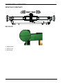
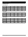
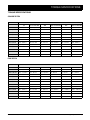
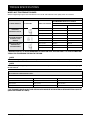
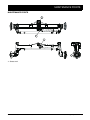
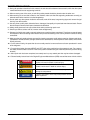
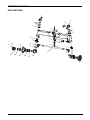
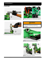
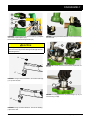
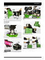
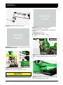
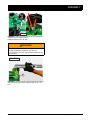
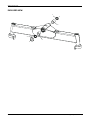
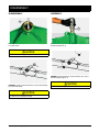
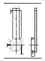
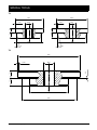
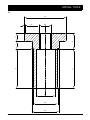
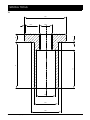
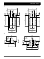
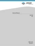
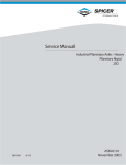
Service Manual
700/211 Axle
ASM-0204E
September 2015
CONTENTS
CONTENTS
INTRODUCTION ................................................................................................................................ 5
MAINTENANCE & LUBRICATION .................................................................................................... 7
DEFINITION OF VIEWPOINTS ...................................................................................................................... 7
DATA PLATE ................................................................................................................................................. 7
CONVERSION TABLES ................................................................................................................................ 8
UNITS OF PRESSURE ............................................................................................................................. 8
UNIT OF WEIGHT .................................................................................................................................... 8
UNITS OF TORQUE ................................................................................................................................. 8
TORQUE SPECIFICATIONS ......................................................................................................................... 9
COARSE PITCH ....................................................................................................................................... 9
FINE PITCH .............................................................................................................................................. 9
WHEEL NUT TIGHTENING TORQUES .................................................................................................... 10
MAINTENANCE POINTS .............................................................................................................................. 11
MAINTENANCE INTERVALS ........................................................................................................................ 12
GREASING FREQUENCY ........................................................................................................................ 12
LUBRICANT & SEALANT SPECIFICATIONS ................................................................................................ 13
SAFETY PRECAUTIONS ................................................................................................................... 15
STEERING KNUCKLE ....................................................................................................................... 17
EXPLODED VIEW .......................................................................................................................................... 17
DISASSEMBLY ............................................................................................................................................. 18
ASSEMBLY ................................................................................................................................................... 21
TRUNNION ......................................................................................................................................... 25
EXPLODED VIEW .......................................................................................................................................... 25
DISASSEMBLY ............................................................................................................................................. 26
ASSEMBLY ................................................................................................................................................... 26
TOE-IN ............................................................................................................................................... 27
ADJUSTMENT .............................................................................................................................................. 27
TROUBLESHOOTING ....................................................................................................................... 29
SPECIAL TOOLS ............................................................................................................................... 31
T1
T2
T3
T4
T5
T6
T7
.................................................................................................................................................................. 31
.................................................................................................................................................................. 32
.................................................................................................................................................................. 32
.................................................................................................................................................................. 33
.................................................................................................................................................................. 34
.................................................................................................................................................................. 35
.................................................................................................................................................................. 35
ASM-0204E - 700/211 Axle Service Manual
Dana Holding Corporation
3
4
Dana Holding Corporation
ASM-0204E - 700/211 Axle Service Manual
INTRODUCTION
The efficiency and continued operation of mechanical units depend on constant, correct maintenance and also on efficient repair work, should there be a break-down or malfunction. The instructions contained in this manual have been based on a complete overhaul of the unit. However, it is up to the mechanic to decide whether or not it is necessary to assemble only individual
components, when partial repair work is needed. The manual provides a quick and sure guide which, with the use of photographs and diagrams illustrating the various phases of the operations, allows accurate work to be performed.All the information
needed for correct disassembly, checks and assembly of each individual component is set out below. In order to remove the
differential unit from the vehicle, the manuals provided by the vehicle manufacturer should be consulted. In describing the following operations it is presumed that the unit has already been removed from the vehicle.
IMPORTANT: In order to facilitate work and protect both working surfaces and operators, it is advisable to use proper equipment such as: trestles or supporting benches, plastic or copper hammers, appropriate levers, pullers and specific spanners or
wrenches. Before going on to disassemble the parts and drain the oil, it is best to thoroughly clean the unit, removing any encrusted or accumulated grease.
INTRODUCTORY REMARKS: All the disassembled mechanical units should be thoroughly cleaned with appropriate products
and restored or replaced if damage, wear, cracking or seizing have occurred. In particular, thoroughly check the condition of
all moving parts (bearings, gears, crown wheel and pinion, shafts) and sealing parts (O-rings, oil shields) which are subject to
major stress and wear. In any case, it is advisable to replace the seals every time a component is overhauled or repaired. During
assembly, the sealing rings must be lubricated on the sealing edge. In the case of the crown wheel and pinion, replacement of
one component requires the replacement of the other one. During assembly, the prescribed pre-loading, backlash and torque
of parts must be maintained.
SPECIFIC EQUIPMENT AND SPARE PARTS: The drawings of all specific tools required for maintenance and repair work can
be found at the end of this manual ; spare parts may be ordered either from the vehicle manufacturer or directly from the Service
Centers or Authorized Distributors of Dana Holding.
ASM-0204E - 700/211 Axle Service Manual
Dana Holding Corporation
5
6
Dana Holding Corporation
ASM-0204E - 700/211 Axle Service Manual
MAINTENANCE & LUBRICATION
DEFINITION OF VIEWPOINTS
DATA PLATE
1 - Model number
2 - Serial number
3 - Axle number
ASM-0204E - 700/211 Axle Service Manual
Dana Holding Corporation
7
CONVERSION TABLES
CONVERSION TABLES
UNITS OF PRESSURE
Atm
Bar
MPa
Pa
PSI
Atm
1
1
0,1
105
14,4
Bar
1
1
0,1
105
14,4
MPa
10
10
1
106
144
Pa
0,00001
0,00001
10-6
1
-
PSI
-
-
-
-
1
N
daN
kN
kg
lbs
UNIT OF WEIGHT
1N
1
0,1
0,001
0,102
0,225
1daN
10
1
0,01
1,02
2,25
1kN
1000
100
1
102
225
1kg
9,81
0,981
0,00981
1
2,205
UNITS OF TORQUE
N·m
daN·m
kN·m
kg·m
lb·in
1N·m
1
0,1
0,001
0,102
8,854
1daN·m
10
1
0,01
1,02
88,54
1kN·m
1000
100
1
102
8854
1kg·m
9,81
0,981
0,00981
1
86,8
1 lb·in
0,1129
0,01129
0,0001129
0,01152
1
8
Dana Holding Corporation
ASM-0204E - 700/211 Axle Service Manual
TORQUE SPECIFICATIONS
TORQUE SPECIFICATIONS
COARSE PITCH
SIZE OF BOLT
TYPE OF BOLT
8.8
8.8 + Loctite 270
10.9
10.9 + Loctite 270
12.9
12.9 + Loctite 270
M6 x 1 mm
9,5 – 10,5 N·m
10,5 – 11,5 N·m
14,3 – 15,7 N·m
15,2 – 16,8 N·m
16,2 – 17,8 N·m
18,1 – 20 N·m
M8 x 1,25 mm
23,8 – 26,2 N·m
25,6 – 28,4 N·m
34,2 – 37,8 N·m
36,7 – 40,5 N·m
39 – 43 N·m
43,7 – 48,3 N·m
M10 x 1,5 mm
48 – 53 N·m
52 – 58 N·m
68 – 75 N·m
73 – 81 N·m
80 – 88 N·m
88 – 97 N·m
M12 x 1,75 mm
82 – 91 N·m
90 – 100 N·m
116 – 128 N·m
126 – 139 N·m
139 – 153 N·m
152 – 168 N·m
M14 x 2 mm
129 – 143 N·m
143 – 158 N·m
182 – 202 N·m
200 – 221 N·m
221 – 244 N·m
238 – 263 N·m
M16 x 2 mm
200 – 221 N·m
219 – 242 N·m
283 – 312 N·m
309 – 341 N·m
337 – 373 N·m
371 – 410 N·m
M18 x 2,5 mm
276 – 305 N·m
299 – 331 N·m
390 – 431 N·m
428 – 473 N·m
466 – 515 N·m
509 – 562 N·m
M20 x 2,5 mm
390 – 431 N·m
428 – 473 N·m
553 – 611 N·m
603 – 667 N·m
660 – 730 N·m
722 – 798 N·m
M22 x 2,5 mm
523 – 578 N·m
575 – 635 N·m
746 – 824 N·m
817 – 903 N·m
893 – 987 N·m
974 – 1076 N·m
M24 x 3 mm
675 – 746 N·m
732 – 809 N·m
950 – 1050 N·m
1040 – 1150 N·m
1140 – 1260 N·m
1240 – 1370 N·m
M27 x 3 mm
998 – 1103 N·m
1088 – 1202 N·m
1411 – 1559 N·m
1539 – 1701 N·m
1710 – 1890 N·m
1838 – 2032 N·m
M30 x 3,5 mm
1378 – 1523 N·m
1473 – 1628 N·m
1914 – 2115 N·m
2085 – 2305 N·m
2280 – 2520 N·m
2494 – 2757 N·m
FINE PITCH
SIZE OF BOLT
TYPE OF BOLT
8.8
8.8 + Loctite 270
10.9
10.9 + Loctite 270
12.9
12.9 + Loctite 270
M8 x 1 mm
25,7 – 28,3 N·m
27,5 – 30,5 N·m
36,2 – 39,8 N·m
40 – 44 N·m
42,8 – 47,2 N·m
47,5 – 52,5 N·m
M10 x 1,25 mm
49,4 – 54,6 N·m
55,2 – 61 N·m
71,5 – 78,5 N·m
78 – 86 N·m
86 – 94 N·m
93 – 103 N·m
M12 x 1,25 mm
90 – 100 N·m
98 – 109 N·m
128 – 142 N·m
139 – 154 N·m
152 – 168 N·m
166 – 184 N·m
M12 x 1,5 mm
86 – 95 N·m
94 – 104 N·m
120 – 132 N·m
133 – 147 N·m
143 – 158 N·m
159 – 175 N·m
M14 x 1,5 mm
143 – 158 N·m
157 – 173 N·m
200 – 222 N·m
219 – 242 N·m
238 – 263 N·m
261 – 289 N·m
M16 x 1,5 mm
214 – 236 N·m
233 – 257 N·m
302 – 334 N·m
333 – 368 N·m
361 – 399 N·m
394 – 436 N·m
M18 x 1,5 mm
312 – 345 N·m
342 – 378 N·m
442 – 489 N·m
485 – 536 N·m
527 – 583 N·m
580 – 641 N·m
M20 x 1,5 mm
437 – 483 N·m
475 – 525 N·m
613 – 677 N·m
674 – 745 N·m
736 – 814 N·m
808 – 893 N·m
M22 x 1,5 mm
581 – 642 N·m
637 – 704 N·m
822 – 908 N·m
903 – 998 N·m
998 – 1103 N·m
1078 – 1191 N·m
M24 x 2 mm
741 – 819 N·m
808 – 893 N·m
1045 – 1155 N·m
1140 – 1260 N·m
1235 – 1365 N·m
1363 – 1507 N·m
M27 x 2 mm
1083 – 1197 N·m
1178 – 1302 N·m
1520 – 1680 N·m
1672 – 1848 N·m
1834 – 2027 N·m
2000 – 2210 N·m
M30 x 2 mm
1511 – 1670 N·m
1648 – 1822 N·m
2138 – 2363 N·m
2332 – 2577 N·m
2565 – 2835 N·m
2788 – 3082 N·m
ASM-0204E - 700/211 Axle Service Manual
Dana Holding Corporation
9
TORQUE SPECIFICATIONS
WHEEL NUT TIGHTENING TORQUES
Wheel nut tightening torques recommended from rim's O.E.M. with reference to the quality of the rim's material.
WHEEL NUT TIGHTENING TORQUES
RECOMMENDED WHEEL NUTS TORQUE
CHARACTERISTICS
ILLUSTRATION
WHEEL STUD THREAD
RIM MATERIAL QUALITY
ST 37
**ST 52
M18 x 1,5 mm
330 N·m
460 N·m
M20 x 1,5 mm
490 N·m
630 N·m
M22 x 1,5 mm
630 N·m
740 N·m
FLAT COLLAR WHEEL
NUTS WITH SEPARATE
SPHERICAL LOCK
WASHER
M18 x 1,5 mm
270 N·m
360 N·m
M20 x 1,5 mm
360 N·m
450 N·m
M22 x 1,5 mm
460 N·m
550 N·m
WHEEL NUTS WITH INTEGRATE SEAT
CAPTIVE WASHER
M18 x 1,5 mm
260 N·m
360 N·m
M20 x 1,5 mm
350 N·m
500 N·m
M22 x 1,5 mm
450 N·m
650 N·m
WHEEL NUTS WITH
INTEGRATE
SPHERICAL COLLAR
**RIM MATERIAL ST 52 IS RECOMMENDED BY DANA ON AXLE APPLICATIONS. IT IS THE OPTIMUM MATERIAL FOR TIGHTENING THE RIM TO THE HUB.
NOTE:
The wheel nut tightening torque is related only on nut thread and stud thread dry (without oil or any lubricant).
NOTE:
The wheel nut tightening torque takes into consideration not only the nut + stud characteristics, but also the quality of
the rim material.
THE DANA OFFICIAL TIGHTENING TORQUE TABLE, INCLUDED IN EACH SERVICE MANUAL, SHOWS THE TORQUE FIGURE RELATED TO THE BOLT CHARACTERISTIC ONLY .
DANA OFFICIAL TIGHTENING TORQUE TABLE
NUT MATERIAL QUALITY 8.8 & 10.9
STUD MATERIAL QUALITY 10.9
*TORQUE RANGE
M18 x 1,5 mm
M18 x 1,5 N·m
442 - 489 N·m
M20 x 1,5 mm
M20 x 1,5 N·m
613 - 677 N·m
M22 x 1,5 mm
M22 x 1,5 N·m
822 - 908 N·m
*THE TORQUE FIGURE ON NUT AND STUD COUPLING MUST BE RELATED ON STUD MATERIAL QUALITY
(DANA AXLES ARE 10.9 ONLY).
10
Dana Holding Corporation
ASM-0204E - 700/211 Axle Service Manual
MAINTENANCE POINTS
MAINTENANCE POINTS
1
1
1
1
1 - Grease zerk
ASM-0204E - 700/211 Axle Service Manual
Dana Holding Corporation
11
MAINTENANCE INTERVALS
MAINTENANCE INTERVALS
GREASING FREQUENCY
In the axle assembly four greasing points have been provided at following parts
2 nos. on kingpin, 1 no. on center pivot tube & 1 no on cylinder fixing pin.
Wheel hub assembly is protected with a cassette seal, which is not to be greased externally.
FOLLOWING GREASING FREQUENCY IS RECOMMENDED
For Pudding Field: Greasing is required to do externally after every 10 hrs of paddy operation at all greasing points.
For Dry /Normal Field: Greasing is required to do externally once in 100 hrs of tractor operation at all greasing points.
Do not take out the hub. But if some impurities or improper hub rotation observed, then disassemble the wheel hub.
It should be noted that once hub is removed from wheel end assembly, cassette seal must be replaced with the new cassette
seal as it gets damaged once disassembled. Also once kingpin seals are removed from their position, they get damaged while
removing & hence they must be replaced.
12
Dana Holding Corporation
ASM-0204E - 700/211 Axle Service Manual
LUBRICANT & SEALANT SPECIFICATIONS
LUBRICANT & SEALANT SPECIFICATIONS
1 - Locking, sealing and lubricating materials referred to in this manual are the same used in the shop-floor.
2 - The table below gives an account of the typical applications of each single material, in order to facilitate replacement with
similar products marketed by different brand names with different trade marks.
LOCTITE 242
Anaerobic product apt to prevent the loosening of screws, nuts and plugs. Used for medium-strength locking. Before using it,
completely remove any lubricant by using the specific activator.
LOCTITE 243
The oleocompatible alternative to 242. Does not require the activation of lubricated surfaces.
LOCTITE 270
Anaerobic product for very-high strength locking of screws and nuts. Before using it, completely remove any lubricant by using
the specific activator.
To remove parts, it may be necessary to heat them at 80°C approximately.
LOCTITE 275
Anaerobic product suitable for high-strength locking and sealing of large threaded parts, bolts and stud bolts, for pipe sealing
and for protecting parts against tampering; suitable for sealing coupling surfaces with a maximum diametrical clearance of 0.25
mm.
LOCTITE 512
Anaerobic product for the hermetic sealing of flanged units and screw holes communicating with fluids. Can seal clearances
between flanges up to 0.2 mm.
LOCTITE 577
Quick anaerobic sealant for sealing threaded portions of conical or cylindrical unions up to M80. Before using it, remove any
lubricant with the specific activator. After polymerisation, disassembly may result rather difficult, so heating may be necessary
for larger diameters.
LOCTITE 638
Anaerobic adhesive for fast and high-strength gluing of cylindrical metal joints (hub on shaft). Can glue together parts with clearance ranging between 0.1 and 0.25 mm.
LOCTITE 648
Anaerobic adhesive for fast and medium-strength gluing of cylindrical metal joints (hub on shaft). Can glue together parts with
radial clearance below 0.1 mm.
AREXONS (REPOSITIONABLE JOINTING COMPOUND FOR SEALS)
Solvent-based sealing compound for elastic seals, drying through evaporation. Used for sealing the outer diameter of sealing
rings for rotating shafts with outer metal reinforcement.
SILICONE
Semi-fluid adhesive material used for sealing and filling and to protect components from environmental and physical elements.
Polymerises with non-corrosive dampness.
TECNO LUBE/101 (SILICONE-BASED GREASE)
Highly adhesive synthetic grease, with silicone compounds added.
Applied to adjustment screws with hole communicating with oil-type fluids.
Used when frequent adjusting is required.
MOLIKOTE (DOW CORNING)
Lubricating compound containing molybdenum disulphide, used to lubricate articulation pins and to prevent sticking and oxidation of parts that are not lubricated on a regular basis.
(LITHIUM-BASED) GREASE
Applied to bearings, sliding parts and used to lubricate seals or parts during assembly.
ASM-0204E - 700/211 Axle Service Manual
Dana Holding Corporation
13
LUBRICANT & SEALANT SPECIFICATIONS
14
Dana Holding Corporation
ASM-0204E - 700/211 Axle Service Manual
SAFETY PRECAUTIONS
1 - During all operations described in this manual, the axle should be fastened onto a trestle, while the other parts
mentioned should rest on supporting benches.
2 - When removing one of the arms, an anti-tilting safety trestle should be placed under the other arm.
3 - When working on an arm that is fitted on the machine, make sure that the supporting trestles are correctly po-
sitioned and that the machine is locked lengthways.
4 - Do not admit any other person inside the work area; mark off the area, hang warning signs and remove the igni-
tion key from the machine.
5 - Use only clean, quality tools; discard all worn, damaged, lowquality or improvised wrenches and tools. Ensure
that all torque wrenches have been checked and calibrated.
6 - Always wear gloves and non-slip rubber shoes when performing repair work.
7 - Should you stain a surface with oil, remove marks straight away.
8 - Dispose of all lubricants, seals, rags and solvents once work has been completed. Treat them as special waste
and dispose of them according to the relative law provisions obtaining in the country where the axles are being
overhauled.
9 - Make sure that only weak solvents are used for cleaning purposes; avoid using turpentine, dilutants and toluol,
xylolbased or similar solvents; use light solvents such as Kerosene, mineral spirits or water-based, environment
friendly solvents.
10 - For the sake of clarity, the parts that do not normally need to be removed have not been reproduced in some
of the diagrams.
11 - For agricultural axles, the terms RIGHT and LEFT refer to the position from the operator's seat. For construc-
tion axles, the terms RIGHT and LEFT refer to the position outside facing the machine (with the input drive facing
forward)
12 - After repair work has been completed, accurately touch up any coated part that may have been damaged.
13 - Follow all safety instructions in the Original Equipment Manufacturer (OEM) manual that came with the vehicle.
DANGER
Indicates an imminently hazardous situation which, if not
avoided, will result in death or serious injury.
WARNING
Indicates an imminently hazardous situation which, if not
avoided, could result in death or serious injury.
CAUTION
Indicates a situation which, if not avoided, may result in
damage to components.
NOTICE
Indicates information which may make product service
easier to perform.
ASM-0204E - 700/211 Axle Service Manual
Dana Holding Corporation
15
LUBRICANT & SEALANT SPECIFICATIONS
16
Dana Holding Corporation
ASM-0204E - 700/211 Axle Service Manual
STEERING KNUCKLE
EXPLODED VIEW
11
13
12
14
3
13
14
16
8
17
6
22
21
15
28
5
18
25
24
29
30
2
4
10
23
1
6
9
20
ASM-0204E - 700/211 Axle Service Manual
Dana Holding Corporation
17
DISASSEMBLY
DISASSEMBLY
4
5
6
3
1
FIGURE 1: Remove the cylinder nut (1).
FIGURE 3: Loosen and remove the grease zerk. Remove the
snap ring (3), the capscrew (4) and the steering cylinder pin
(6).
WARNING
Personal injury can result when removing snap ring.
The appropriate safety equipment must be worn.
To avoid injury to your eyes, wear protective glasses during
this procedure.
2
FIGURE 2: Disconnect the tapered pins of the cylinder (2)
from the steering knuckle using a suitable diameter driver.
6 8
FIGURE 4: Extract the cylinder (2) using a plastic hammer.
Remove the two spacers (8) and the two seals (6)
10
10
9
FIGURE 5: Remove the tie rod nuts (9).
Disconnect the tapered pins of the tie rod (10) using a puller.
18
Dana Holding Corporation
ASM-0204E - 700/211 Axle Service Manual
DISASSEMBLY
12
11
13
14
16
17
15
18
FIGURE 6: Loosen and remove the hex screw (11) complete
with locker (12) and spacer (13).
Remove the complete steering knuckle (20).
FIGURE 9: Using an internal extractor, remove the bushings
from the axle.
21
23
CAUTION
Removing the capscrew (11) the steering case could come
out from its seat, support the steering knuckle (20) with a suitable lifting device.
14
22
23
21
FIGURE 10: Loosen and remove the screws (21) and the cover (23).
17
FIGURE 7: Using an internal extractor, remove the seal rings
(14, 17) from the axle.
25
T1
FIGURE 11: Using special tool T1 (see drawing T1 p. 31), remove the ring nut (25).
16
FIGURE 8: Using an internal extractor, remove the bearing
(16) from the axle.
ASM-0204E - 700/211 Axle Service Manual
Dana Holding Corporation
19
DISASSEMBLY
24
28
29
30
FIGURE 12: Disassemble wheel hub (24) components:
Outer bearing (28)
Inner bearing (29)
Seal ring (30).
20
Dana Holding Corporation
ASM-0204E - 700/211 Axle Service Manual
ASSEMBLY
ASSEMBLY
21
24
23
22
23
21
28
9 - 11 N·m
29
30
FIGURE 13: Using a press and suitable tools (see drawings
T2 p. 32 and T3 p. 32) install wheel hub (24) components:
Outer bearing (28)
Inner bearing (29)
Seal ring (30).
FIGURE 16: Install the cover in its seat, and tighten the capscrews (21) complete with washers (22) to a torque of 9 - 11
N·m.
50 - 70 N·m
25
T1
FIGURE 17: Using special tool T6 (see drawing T6 p. 35), install the bushings in their seats.
FIGURE 14: Install the ring nut (25), and using the special tool
T1 (see drawing T1 p. 31), tighten to a torque of 50 - 70 N·m.
T7
T7
23
17
14
FIGURE 18: Using special tool T7 (see drawing T7 p. 35), install the seal rings (14, 17) in their seats.
Anabond 676
FIGURE 15: Spread the cover with Anabond sealant 676 or
equivalent.
ASM-0204E - 700/211 Axle Service Manual
Dana Holding Corporation
21
ASSEMBLY
MISSING
IMAGE
16
FIGURE 19: Install the bearing (16) in its seat.
MISSING
IMAGE
FIGURE 22: Check vertical gap using a lever.
King pin Preload Draw = 0,1 - 0,3 mm
S = First step shim - Measured Backlash - Preload Draw =
Example
First step Shim = 2.5 mm
Measured Backlash = 1 mm
S = 2.5 mm - 1 mm - 0,2 mm = 1,3 mm
S = 1,3 mm
120 - 130 N·m
9
FIGURE 20: Prepare a series of shims (13) of 2.5 mm to be
assembled under the locker.
12
11
16
17
15
18
FIGURE 23: Insert the tie rod pins in the steering knuckle (20)
and lock nuts (9) into position using a torque of 120 - 130
N·m.
13
14
180 - 220 N·m
FIGURE 21: Install the steering knuckle (20).
Install the spacer (13) and the locker (12).
Tighten the screw (11) to a torque of 180 - 220 N·m.
6 8
CAUTION
Pay attention not to damage the sealing rings.
FIGURE 24: Install the two spacers (8) and the two seals (6)
Fit the steering cylinder (2) into its seat.
22
Dana Holding Corporation
ASM-0204E - 700/211 Axle Service Manual
ASSEMBLY
4
5
6
3
25 N·m
FIGURE 25: Install the steering cylinder pin (6), and tigten the
capscrew (4) to a torque of 25 N·m.
Install the snap ring (3) in its seat.
WARNING
Personal injury can result when removing snap ring.
The appropriate safety equipment must be worn.
To avoid injury to your eyes, wear protective glasses during
this procedure.
120 - 135 N·m
1
FIGURE 26: Insert the cylinder rod in the steering knuckle (20)
and lock nuts (9) into position using a torque of 120 - 135
N·m.
ASM-0204E - 700/211 Axle Service Manual
Dana Holding Corporation
23
ASSEMBLY
24
Dana Holding Corporation
ASM-0204E - 700/211 Axle Service Manual
TRUNNION
EXPLODED VIEW
1
2
4
3
ASM-0204E - 700/211 Axle Service Manual
Dana Holding Corporation
25
DISASSEMBLY
DISASSEMBLY
ASSEMBLY
1
3
FIGURE 1: Using a screwdriver, remove the seal rings (1, 4)
from their seats.
FIGURE 3: Using special tool T4 (see drawing T4 p. 33), install the bushings (2, 3).
CAUTION
1
Be careful to not damage the seats.
2
3
FIGURE 2: Using an internal extractor, remove the bushings
(2, 3) from their seats.
4
FIGURE 4: Using special tool T5 (see drawing T5 p. 34), install the sealing rings (1, 4).
CAUTION
Assemble in correct position.
CAUTION
Be careful to not damage the seats.
26
Dana Holding Corporation
ASM-0204E - 700/211 Axle Service Manual
TOE-IN
ADJUSTMENT
1 - Supporting the axle with a hoist and install axle into vehicle. Install front wheels.
NOTE:
The toe-in adjustment must be performed on the vehicle.
2 - Jack up front axle so tires are off floor.
3 - Rotate tire by hand and scribe a line near the center of each of the front tires.
NOTE:
One of the tie rod ends and jam nut has left-hand threads.
4 - Measure and record the distance between the lines at the front and the rear of the tire at about axle height. The front measurement should be less than the rear measurement.
5 - If measurement is not correct, loosen jam nuts on both ends of tie rod and turn the tie rod using a wrench to increase or
decrease the amount of toe until the measured dimension is 0–0.125 in. [0–2 mm] between the front and rear.
6 - Apply Loctite 262 and tighten the jam nuts to 85–96 lbs. ft. [200– 220 N•m].
ASM-0204E - 700/211 Axle Service Manual
Dana Holding Corporation
27
ADJUSTMENT
28
Dana Holding Corporation
ASM-0204E - 700/211 Axle Service Manual
TROUBLESHOOTING
SNO.
1)
CONDITION
POSSIBLE CAUSES
REMEDY
Wheel Hub bearing preload not correct.
Check the preload, bearing condition.
Bearing failure, Oil seal failure.
Replace the bearing, ring nut and Seals.
Excessive king pin radial play.
Replace the bushes, kingpin bottom
and top seal
Excessive play in drop arm.
Adjust the endplay.
Center tube thrust washer worn out.
Replace the thrust washer.
Excessive Wheel Wobbling
2)
Hitting Noise from front axle support
3)
Hitting noise from kingpin side
4)
Incorrect Steering function
Excessive play in center tube bushes,
Replace the bush and seals
worn out bushes
Excessive axial float in king pin tube.
Replace the Kingpin thrust washer of
required thickness
Ball joint failure
Replace the ball joints.
Incorrect toe-in
Adjust the toe-in setting.
NOTE:
If in doubt please contact authorized person for more details and clarifications.
Continuous improvement is always a part of process, please refer proper documents for better results.
ASM-0204E - 700/211 Axle Service Manual
Dana Holding Corporation
29
ADJUSTMENT
30
Dana Holding Corporation
ASM-0204E - 700/211 Axle Service Manual
SPECIAL TOOLS
SPECIAL TOOLS
T1
10
300
5X45°
30
ø5
5
ø6
4,8
6,5
2,8
7
17,5
ASM-0204E - 700/211 Axle Service Manual
Dana Holding Corporation
31
SPECIAL TOOLS
T2
ø72,5
ø64
1x45°
M16
12
12
10
M16
10
1x45°
ø57
ø67
15°
13°
T3
ø90
M16
10
10
0,5
1x45°
ø56
ø79
32
Dana Holding Corporation
ASM-0204E - 700/211 Axle Service Manual
SPECIAL TOOLS
T4
ø54
M16
49
50
9
20
10
1x45°
ø25
ø32
ø35.5
ASM-0204E - 700/211 Axle Service Manual
Dana Holding Corporation
33
SPECIAL TOOLS
T5
ø54
M16
48
57
10
1
1x45°
ø25
ø31
ø39
34
Dana Holding Corporation
ASM-0204E - 700/211 Axle Service Manual
SPECIAL TOOLS
T6
ø50
1x45°
10
40,5
50
40,5
50
10
M16
0,5
M16
0,5
1x45°
ø44
ø25
ø25
ø35
ø35
ø38.5
ø38.5
T7
ø60
ø35
8
15
7
M16
10
1x45°
1,5
M16
10
1x45°
ø90
ø44,5
ø60
ø74
ASM-0204E - 700/211 Axle Service Manual
Dana Holding Corporation
35
Copyright 2015 Dana Holding Corporation
All content is subject to copyright by Dana and may not
be reproduced in whole or in part by any means,
electronic or otherwise, without prior written approval.
THIS INFORMATION IS NOT INTENDED FOR SALE OR
RESALE, AND THIS NOTICE MUST REMAIN ON ALL
COPIES.
For product inquiries or support,
visit www.dana.com or call 419-887-6445
For other service publications,
visit www.SpicerParts.com/literature.asp
For online service parts ordering,
visit www.SpicerParts.com/order.asp