1
Black plate (3,1)
Foreword
GUID-723F5C4A-DB40-4277-9BA9-8E30459C80BE
Welcome to the growing family of new NISSAN
owners. This vehicle has been delivered to you with
confidence. It has been produced using the latest
techniques and strict quality control.
When readingGUID-C8DEAFE3-8206-4E85-B889-D50C840BCAE8
the manual
This manual was prepared to help you understand the
operation and maintenance of your vehicle so that you
may enjoy many kilometers (miles) of driving pleasure.
Please read through this manual before operating your
vehicle.
All information, specifications and illustrations in this
manual are those in effect at the time of printing.
NISSAN reserves the right to change specifications or
designs without notice and without obligation.
A separate Warranty Information & Maintenance Booklet explains details about the warranties covering your
vehicle.
Your NISSAN dealer knows your vehicle best. When
you require any service or have any questions, we will
be glad to assist you with the extensive resources
available for you.
IMPORTANT SAFETY
INFORMATION
GUID-C059A185-90B0-4BF8-811E-FE132C05C8E8
Reminders for GUID-8B0D871A-F054-40DF-9989-9BE49595AF34
safety!
Follow these important driving rules to help ensure a
safe and complete trip for you and your passengers!
.
.
.
.
.
NEVER drive under the influence of alcohol
or drugs.
ALWAYS observe posted speed limits and
never drive too fast for conditions.
ALWAYS use your seat belts and appropriate
child restraint systems. Preteen children
should be seated in the rear seat.
ALWAYS provide information about the
proper use of vehicle safety features to all
occupants of the vehicle.
ALWAYS review this Owner’s Manual for
important safety information.
Condition:
This manual includes information for all options
available on this model. Therefore, you may find some
information that does not apply to your vehicle.
MODIFICATION
OF YOUR VEHICLE
GUID-3E2048D4-8318-4062-B859-25EA5478F382
This vehicle should not be modified. Modification could
affect its performance, safety or durability, and may
even violate governmental regulations. In addition,
damage or performance problems resulting from
modifications may not be covered under NISSAN
warranties.
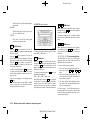
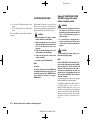
Read first — then
drive safely
GUID-321D95F2-3395-4FF5-AC5D-5024161D0CD8
Before driving your vehicle, read this Owner’s Manual
carefully. This will ensure familiarity with controls and
maintenance requirements, assisting you in the safe
operation of your vehicle.
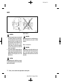
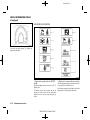
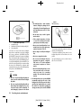
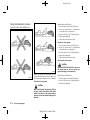
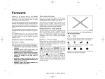
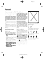
Throughout this manual we have used the symbol
followed by the word WARNING. This is used
to indicate the presence of a hazard that could cause
death or serious personal injury. To avoid or reduce the
risk, the procedures must be followed precisely.
The symbol
followed by the word CAUTION is
also used throughout this manual to indicate the
presence of a hazard that could cause minor or
moderate personal injury or damages to your vehicle.
To avoid or reduce the risk, the procedures must be
followed carefully.
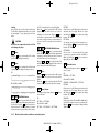
[ Edit: 2013/ 2/ 25 Model: K13-A ]
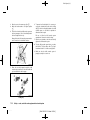
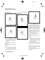
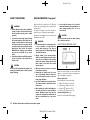
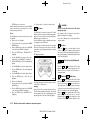
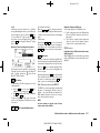
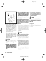
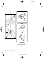
SIC0697
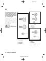
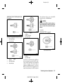
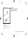
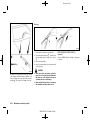
If you see this symbol, it means “Do not do this” or
“Do not let this happen”.
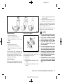
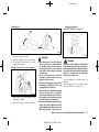
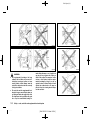
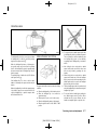
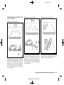
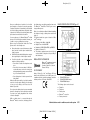
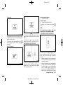
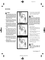
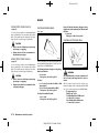
NOS1274
If you see a symbol similar to these in an illustration, it
means the arrow points to the front of the vehicle.
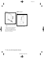
NOS1275
Arrows in an illustration that are similar to these
indicate movement or action.
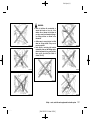
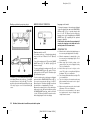
NOS1276
Arrows in an illustration that are similar to these call
attention to an item in the illustration.
Black plate (4,1)
Bluetooth® is a trademark owned
by Bluetooth SIG, Inc. and licensed to Clarion Co., Ltd. and
Daewoo IS Corp.
C 2013 NISSAN MOTOR CO., LTD.
*
Condition:
[ Edit: 2013/ 2/ 25 Model: K13-A ]
Black plate (2,1)
Black plate (1,1)
Table of
Contents
Illustrated table of contents
0
Safety — seats, seat belts and supplemental
restraint system
1
Instruments and controls
2
Pre-driving checks and adjustments
3
Monitor, Heater and air conditioner, and audio
system
4
Starting and driving
5
In case of emergency
6
Appearance and care
7
Maintenance and do-it-yourself
8
Technical information
9
10
Index
Condition:
[ Edit: 2013/ 2/ 25 Model: K13-A ]
Black plate (2,1)
Black plate (5,1)
0 Illustrated table of contents
Seats, seat belts and supplemental restraint system (SRS) .......
.... 0-2
Exterior front ..............................................................................................
....
0-3
Exterior rear ...............................................................................................
....
0-5
Passenger compartment ........................................................................
....
0-7
Instrument panel ....
...................................................................................... 0-8
Left-Hand Drive (LHD) model ......................................................
....
0-8
Right-Hand Drive (RHD) model (Type A) ...................................
....
0-9
Right-Hand Drive (RHD) model (Type B) ....
............................... 0-10
Condition:
Right-Hand Drive (RHD) model (Type C) .............................
....
Meters and gauges .............................................................................
....
Engine compartment ....
.........................................................................
HR12DDR engine model ..........................................................
....
HR12DE engine model ..............................................................
....
HR15DE engine model ..............................................................
....
K9K engine model .......................................................................
....
[ Edit: 2013/ 2/ 25 Model: K13-A ]
0-11
0-12
0-15
0-15
0-16
0-17
0-18
Black plate (6,1)
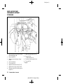
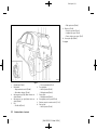
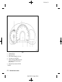
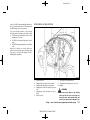
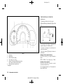
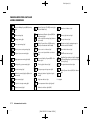
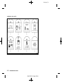
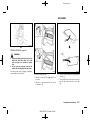
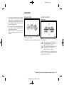
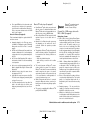
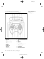
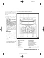
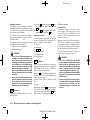
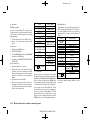
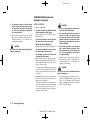
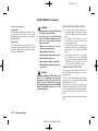
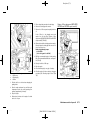
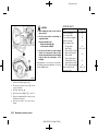
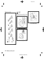
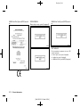
SEATS, SEAT BELTS AND
SUPPLEMENTAL RESTRAINT
SYSTEM (SRS)
GUID-9F4D2D75-FC90-4B85-A981-539364187A6D
JVC0101X
1.
2.
3.
4.
5.
6.
7.
8.
0-2
Condition:
Child restraint anchor point (for top tether strap
child restraint)* (Page 1-18)
Rear seat belts (P.1-7)
Supplemental curtain side-impact air bags*
(P.1-25)
Head restraints (P.1-5)
Front seat belts (P.1-7)
Supplemental side-impact air bags* (P.1-25)
Supplemental front-impact air bags* (P.1-25)
Rear center seat belts (for three-point type seat
belts)* (P.1-7)
9.
10.
11.
12.
ISOFIX child restraint system* (P.1-17)
Rear seats (P.1-4)
— Child restraints (P.1-13)
Pre-tensioner seat belt system* (P.1-31)
Front seats (P.1-2)
*: if equipped
Illustrated table of contents
[ Edit: 2013/ 2/ 25 Model: K13-A ]
Black plate (7,1)
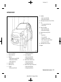
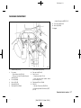
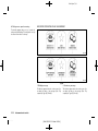
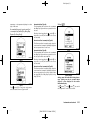
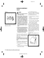
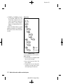
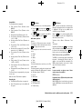
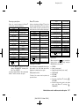
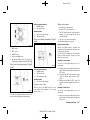
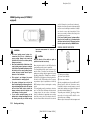
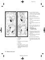
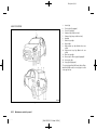
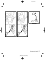
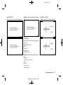
EXTERIOR FRONT
GUID-4F29C80F-8CE1-4BF1-906C-3DF45BAC934D
10.
11.
12.
13.
14.
15.
16.
Headlights
— Switch operation (P.2-33)
— Bulb replacement (P.8-29)
Parking space measurement sensors* (P.5-34)
Tires
— Tires and wheels (P.8-42, P.9-8)
— Flat tire (P.6-2)
Side turn signal lights
— Switch operation (P.2-35)
— Bulb replacement (P.8-30)
Outside rearview mirrors (P.3-22)
Doors
— Keys (P.3-2)
— Door locks (P.3-5)
— Intelligent Key system* (P.3-9)
— Remote keyless entry system* (P.3-7)
— Security system* (P.3-17)
Child safety rear door lock (P.3-7)
*: if equipped
JVC0469X
Type A
1.
2.
3.
4.
5.
6.
Recovery hook (P.6-13)
Engine hood (P.3-19)
Windshield
— Wiper and washer switch (P.2-37)
— Wiper replacement (P.8-21)
— Washer fluid (P.8-23)
Antenna* (P.4-19)
Windows (P.2-40)
Fog lights*
— Switch operation (P.2-36)
7.
8.
9.
— Bulb replacement (P.8-29)
Front turn signal lights
— Switch operation (P.2-35)
— Bulb replacement (P.8-30)
Clearance lights (for Micra Active)
— Switch operation (P.2-33)
— Bulb replacement (P.8-29)
Clearance lights (except for Micra Active)
— Switch operation (P.2-33)
— Bulb replacement (P.8-29)
Illustrated table of contents
Condition:
[ Edit: 2013/ 2/ 25 Model: K13-A ]
0-3
Black plate (8,1)
10.
11.
12.
13.
14.
Tires
— Tires and wheels (P.8-42, P.9-8)
— Flat tire (P.6-2)
Side turn signal lights
— Switch operation (P.2-35)
— Bulb replacement (P.8-30)
Outside rearview mirrors (P.3-22)
Doors
— Keys (P.3-2)
— Door locks (P.3-5)
— Intelligent Key system* (P.3-9)
— Remote keyless entry system* (P.3-7)
— Security system* (P.3-17)
Child safety rear door lock (P.3-7)
*: if equipped
JVC0450X
Type B
1.
2.
3.
4.
5.
6.
0-4
Condition:
Recovery hook (P.6-13)
Engine hood (P.3-19)
Windshield
— Wiper and washer switch (P.2-37)
— Wiper replacement (P.8-21)
— Washer fluid (P.8-23)
Antenna (P.4-19)
Windows (P.2-40)
Front turn signal lights
— Switch operation (P.2-35)
7.
8.
9.
— Bulb replacement (P.8-30)
Fog lights*
— Switch operation (P.2-36)
— Bulb replacement (P.8-29)
Clearance lights
— Switch operation (P.2-33)
— Bulb replacement (P.8-29)
Headlights
— Switch operation (P.2-33)
— Bulb replacement (P.8-29)
Illustrated table of contents
[ Edit: 2013/ 2/ 25 Model: K13-A ]
Black plate (9,1)
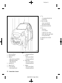
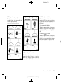
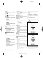
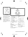
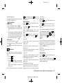
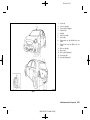
EXTERIOR REAR
GUID-5B9FAF64-0C18-4ABA-84B2-68CDBE51010C
10.
— Intelligent Key system* (P.3-9)
— Remote keyless entry system* (P.3-7)
License plate light (P.8-30)
*: if equipped
JVC0007X
Type A
1.
2.
3.
4.
5.
Stop/tail lights (P.8-30)
Rear window
— Wiper and washer switch* (P.2-38)
— Rear window defogger* (P.2-39)
High-mounted stop light (Model without rear
spoiler) (P.8-30)
High-mounted stop light (Model with rear
spoiler) (P.8-30)
Fuel
— Fuel filler lid (P.3-20)
6.
7.
8.
9.
— Fuel recommendation (P.9-4)
Turn signal lights
— Switch operation (P.2-35)
— Bulb replacement (P.8-30)
Reverse lights/Rear fog light*
— Switch operation (P.2-36)
— Bulb replacement (P.8-30)
Sonar (parking sensor) system* (P.5-34)
Back door (P.3-20)
— Back door operation (P.3-20)
Illustrated table of contents
Condition:
[ Edit: 2013/ 2/ 25 Model: K13-A ]
0-5
Black plate (10,1)
11.
12.
— Bulb replacement (P.8-30)
Back door (P.3-20)
— Back door operation (P.3-20)
— Intelligent Key system* (P.3-9)
— Remote keyless entry system* (P.3-7)
License plate light (P.8-30)
*: if equipped
JVC0451X
Type B
1.
2.
3.
4.
5.
0-6
Condition:
Stop/tail lights (P.8-30)
Rear window
— Wiper and washer switch* (P.2-38)
— Rear window defogger* (P.2-39)
High-mounted stop light (Model without rear
spoiler) (P.8-30)
High-mounted stop light (Model with rear
spoiler) (P.8-30)
Fuel
— Fuel filler lid (P.3-20)
6.
7.
8.
9.
10.
— Fuel recommendation (P.9-4)
Turn signal lights
— Switch operation (P.2-35)
— Bulb replacement (P.8-30)
Reverse lights
— Bulb replacement (P.8-30)
Sonar (parking sensor) system* (P.5-34)
Rearview camera for rearview monitor* (P. 4-2)
Rear fog light*
— Switch operation (P.2-36)
Illustrated table of contents
[ Edit: 2013/ 2/ 25 Model: K13-A ]
Black plate (11,1)
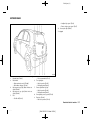
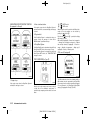
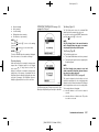
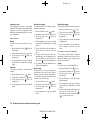
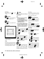
PASSENGER COMPARTMENT
GUID-025177D1-6641-4E78-A6B5-38C0062346DC
12.
13.
— Manual Transmission (MT) (P.5-17)
Front cup holder (P.2-44)
Glove box (P.2-44)
*: if equipped
JVC0102X
1.
2.
3.
4.
5.
6.
Tonneau board* (P.2-45)
Door armrest
— Power window switch* (P.2-40)
— Power door lock switch* (models with power
windows) (P.3-6)
Fuse box (P.8-28)
Sun visor (P.2-45)
Sunshade* (P.2-42)
Room light (P.2-46, P.8-31)
7.
8.
9.
10.
11.
Inside rearview mirror (P.3-21)
Rear cup holder (P.2-44)
Center console
— Heated seats switch* (P.1-3)
— Power door lock switch* (models without
power windows) (P.3-6)
Parking brake (P.3-24, P.8-18)
Shift lever
— Automatic Transmission (AT) (P.5-11)
— Continuously Variable Transmission (CVT)
(P.5-14)
Illustrated table of contents
Condition:
[ Edit: 2013/ 2/ 25 Model: K13-A ]
0-7
Black plate (12,1)
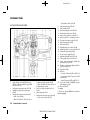
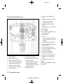
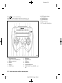
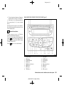
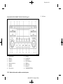
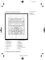
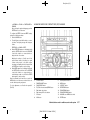
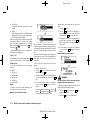
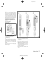
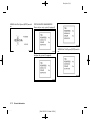
INSTRUMENT PANEL
GUID-98DDFB8E-C28C-4AF8-9161-BB7348069090
LEFT-HAND DRIVE (LHD) MODEL
8.
9.
10.
11.
12.
13.
14.
15.
16.
17.
18.
19.
20.
21.
22.
23.
GUID-8485E838-E199-4C0F-B363-975F75B28CC4
24.
25.
26.
JVI0261X
Example
1.
2.
3.
4.
0-8
Condition:
Vehicle Dynamic Control (VDC) OFF switch*
(P.5-24) or Electronic Stability Program (ESP)
OFF switch* (P.5-27)
Parking space measurement switch* (P.5-34)
Headlight, fog light* and turn signal switch
(P.2-33)
Steering-wheel-mounted controls (left side)*
— Audio control* (P.4-63)
— Bluetooth® Hands-Free Phone System con-
5.
6.
7.
trol (without navigation system)* (P.4-64)
— Bluetooth® Hands-Free Phone System control (with navigation system)**
Driver’s front-impact air bag/Horn (P.1-25,
P.2-40)
Meters and gauges (P.2-6)
Steering-wheel-mounted controls (right side)*
— Cruise control switches* (P.5-30)
Illustrated table of contents
[ Edit: 2013/ 2/ 25 Model: K13-A ]
27.
28.
— Speed limiter switches* (P.5-28)
Wiper and washer switch (P.2-37)
Center ventilator (P.4-5)
Rear window defogger switch* (P.2-39)
Hazard indicator flasher switch (P.6-2)
Heater and air conditioner* control (P.4-6)
Audio system* (P.4-11 or Navigation system**)
Passenger’s front-impact air bag* (P.1-25)
Upper instrument box* (P.2-44)
Side ventilator (P.4-5)
Headlight aiming control switch* (P.2-34)
Outside rearview mirror control switch* (P.3-22)
Fuel filler lid release handle (P.3-20)
Hood lock release handle (P.3-19)
Stop/Start System OFF switch* (P.5-23)
Tilting steering wheel lock lever (P.3-21)
Ignition switch (model without Intelligent Key
system)/steering lock (P.5-5)
Push-button ignition switch (model with Intelligent Key system) (P.5-6)
Cup holder (P.2-44)
Shift lever
— Automatic Transmission (AT) model (P.5-11)
— Continuously Variable Transmission (CVT)
model (P.5-14)
— Manual Transmission (MT) model (P.5-17)
Power outlet* (P.2-43) or USB/AUX connector
(with navigation system)**
Glove box (P.2-44)
*: if equipped
**: Refer to the separate NISSAN Connect Owner’s
Manual (if equipped).
Black plate (13,1)
11.
12.
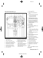
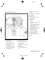
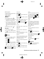
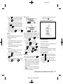
RIGHT-HAND DRIVE (RHD) MODEL (Type A)
GUID-78858CCA-AACD-49C5-9B5E-3B2F2704C1E4
13.
14.
15.
16.
17.
18.
19.
20.
21.
22.
JVI0262X
23.
24.
Example
1.
2.
3.
4.
5.
6.
7.
8.
Side ventilator (P.4-5)
Upper instrument box* (P.2-44)
Passenger’s front-impact air bag* (P.1-25)
Audio system* (P.4-11 or Navigation system**)
Rear window defogger switch* (P.2-39)
Hazard indicator flasher switch (P.6-2)
Heater and air conditioner* control (P.4-6)
Center ventilator (P.4-5)
9.
10.
Wiper and washer switch (P.2-37) or Headlight,
fog light and turn signal switch (P.2-33)
Steering-wheel-mounted controls (left side)*
— Audio control* (P.4-63)
— Bluetooth® Hands-Free Phone System control (without navigation system)* (P.4-64)
— Bluetooth® Hands-Free Phone System control (with navigation system)**
25.
26.
27.
28.
29.
Meters and gauges (P.2-6)
Driver’s front-impact air bag*/Horn (P.1-25,
P.2-40)
Steering-wheel-mounted controls (right side)*
— Cruise control switches* (P.5-30)
— Speed limiter switches* (P.5-28)
Headlight, fog light* and turn signal switch
(P.2-33) or Wiper and washer switch (P.2-37)
Parking space measurement switch* (P.5-34)
Vehicle Dynamic Control (VDC) OFF switch*
(P.5-24, P.5-25) or Electronic Stability Program
(ESP) OFF switch* (P.5-27)
Fuse box (P.8-28)
Glove box (P.2-44)
Power outlet* (P.2-43) or USB/AUX connector
(with navigation system)**
Shift lever
— Automatic Transmission (AT) model (P.5-11)
— Continuously Variable Transmission (CVT)
model (P.5-14)
— Manual Transmission (MT) model (P.5-17)
Cup holder (P.2-44)
Push-button ignition switch (model with Intelligent Key system) (P.5-6)
Tilting steering wheel lock lever (P.3-21)
Ignition switch (model without Intelligent Key
system)/steering lock (P.5-5)
Stop/Start System OFF switch* (P.5-23)
Hood lock release handle (P.3-19)
Fuel filler lid release handle (P.3-20)
Outside rearview mirror control switch* (P.3-22)
Headlight aiming control switch* (P.2-34)
*: if equipped
**: Refer to the separate NISSAN Connect Owner’s
Manual (if equipped).
Illustrated table of contents
Condition:
[ Edit: 2013/ 2/ 25 Model: K13-A ]
0-9
Black plate (14,1)
12.
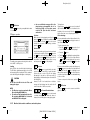
RIGHT-HAND DRIVE (RHD) MODEL (Type B)
GUID-49CE9F94-E9C6-4D5D-A4A3-7B097C7E9802
13.
14.
15.
16.
17.
18.
19.
20.
21.
22.
23.
JVI0170X
Example
1.
2.
3.
4.
5.
6.
7.
8.
Side ventilator (P.4-5)
Upper instrument box* (P.2-44)
Passenger’s front-impact air bag* (P.1-25)
Audio system* (P.4-11 or Navigation system**)
Rear window defogger switch* (P.2-39)
Hazard indicator flasher switch (P.6-2)
Heater and air conditioner* control (P.4-6)
Center ventilator (P.4-5)
0-10
Condition:
9.
10.
11.
Wiper and washer switch (P.2-37)
Steering-wheel-mounted controls (left side)*
— Audio control* (P.4-63)
— Bluetooth® Hands-Free Phone System control (without navigation system)* (P.4-64)
— Bluetooth® Hands-Free Phone System control (with navigation system)**
Meters and gauges (P.2-6)
Illustrated table of contents
[ Edit: 2013/ 2/ 25 Model: K13-A ]
24.
25.
26.
27.
28.
Driver’s front-impact air bag*/Horn (P.1-25,
P.2-40)
Steering-wheel-mounted controls (right side)*
— Cruise control switches* (P.5-30)
— Speed limiter switches* (P.5-28)
Headlight, fog light* and turn signal switch
(P.2-33)
Outside rearview mirror control switch* (P.3-22)
Fuse box (P.8-28)
Glove box (P.2-44)
Power outlet* (P.2-43) or USB/AUX connector
(with navigation system)**
Cup holder (P.2-44)
Shift lever
— Automatic Transmission (AT) model (P.5-11)
— Continuously Variable Transmission (CVT)
model (P.5-14)
— Manual Transmission (MT) model (P.5-17)
Push-button ignition switch (model with Intelligent Key system) (P.5-6)
Tilting steering wheel lock lever (P.3-21)
Ignition switch (model without Intelligent Key
system)/steering lock (P.5-5)
Hood lock release handle (P.3-19)
Fuel filler lid release handle (P.3-20)
Parking space measurement switch* (P.5-34)
Vehicle Dynamic Control (VDC) OFF switch*
(P.5-24)
Headlight aiming control switch* (P.2-34)
*: if equipped
**: Refer to the separate NISSAN Connect Owner’s
Manual (if equipped).
Black plate (15,1)
13.
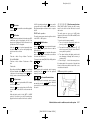
RIGHT-HAND DRIVE (RHD) MODEL (Type C)
GUID-9BAFCD9F-77F5-47BB-BDFD-D12FA3B67B88
14.
15.
16.
17.
18.
19.
20.
21.
22.
23.
24.
25.
26.
27.
Headlight, fog light* and turn signal switch
(P.2-33)
Outside rearview mirror control switch* (P.3-22)
Fuse box (P.8-28)
Glove box (P.2-44)
USB/AUX connector* (P. 4-41, P. 4-48)
Power outlet* (P. 2-43)
Cup holder (P.2-44)
Shift lever
— Continuously Variable Transmission (CVT)
model (P.5-14)
— Manual Transmission (MT) model (P.5-17)
Push-button ignition switch (model with Intelligent Key system) (P.5-6)
Tilting steering wheel lock lever (P.3-21)
Ignition switch (model without Intelligent Key
system)/steering lock (P.5-5)
Hood lock release handle (P.3-19)
Fuel filler lid release handle (P.3-20)
Idling Stop OFF switch* (P. 5-19)
Headlight aiming control switch* (P.2-34)
*: if equipped
JVC0449X
Example
1.
2.
3.
4.
5.
6.
7.
8.
Side ventilator (P.4-5)
Upper instrument box* (P.2-44)
Passenger’s front-impact air bag* (P.1-25)
Audio system* (P.4-11)
Rear window defogger switch* (P.2-39)
Hazard indicator flasher switch (P.6-2)
Heater and air conditioner* control (P.4-6)
Center ventilator (P.4-5)
9.
10.
11.
12.
Wiper and washer switch (P.2-37)
Steering-wheel-mounted controls (left side)*
— Audio control* (P.4-63)
— Bluetooth® Hands-Free Phone System control* (P.4-64)
Meters and gauges (P.2-6)
Driver’s front-impact air bag*/Horn (P.1-25,
P.2-40)
Illustrated table of contents
Condition:
[ Edit: 2013/ 2/ 25 Model: K13-A ]
0-11
Black plate (16,1)
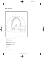
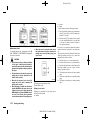
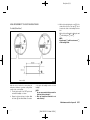
METERS AND GAUGES
GUID-065ED8FC-7483-4045-BD76-0E5802E9C7D3
JVC0453X
Type A
1.
2.
3.
4.
5.
6.
Speedometer (P.2-8)
Trip odometer reset switch/trip computer mode
switch (P.2-8)
Clock adjusting knob (P.2-42)
Automatic Transmission (AT) position indicator*
(P.2-10, P.5-11)
Odometer/twin trip odometer/trip computer
(P.2-8)/clock (P.2-42)
Fuel gauge (P.2-10)
*: if equipped
0-12
Condition:
Illustrated table of contents
[ Edit: 2013/ 2/ 25 Model: K13-A ]
Black plate (17,1)
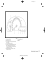
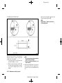
JVC0454X
Type B
1.
2.
3.
4.
5.
6.
Tachometer (P.2-10)
Speedometer (P.2-8)
Trip odometer reset switch/trip computer mode
switch (P.2-8)
Clock adjusting knob (P.2-42)
Automatic Transmission (AT)/Continuously Variable Transmission (CVT) position indicator*
(P.2-10, P.5-11)/Cruise control and speed limiter display* (P.5-30, P.5-28)
Odometer/twin trip odometer/trip computer
(P.2-8)/clock (P.2-42)
7.
Fuel gauge (P.2-10)
*: if equipped
Illustrated table of contents
Condition:
[ Edit: 2013/ 2/ 25 Model: K13-A ]
0-13
Black plate (18,1)
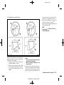
JVC0455X
Type C
1.
2.
3.
4.
5.
6.
Tachometer (P.2-10)
Speedometer (P.2-8)
Vehicle information display (P.2-10, P.2-20)
Trip odometer reset switch (P.2-8)
Automatic Transmission (AT)/Continuously Variable Transmission (CVT) position indicator*
(P.2-10, P.5-11)
Odometer/twin trip odometer/clock (P.2-8)
*: if equipped
0-14
Condition:
Illustrated table of contents
[ Edit: 2013/ 2/ 25 Model: K13-A ]
Black plate (19,1)
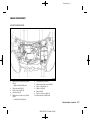
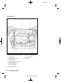
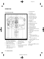
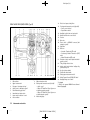
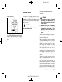
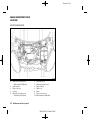
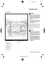
ENGINE COMPARTMENT
GUID-095DCB79-DC2C-4D0E-9537-1ACFFB10F6C9
HR12DDR ENGINE MODEL
GUID-15DFFEDB-5D04-4613-8FE8-4FF21F03A9C1
JVO0032X
1.
2.
3.
4.
5.
Brake and clutch* fluid reservoir (P.8-19,
P.8-20)
— Right-Hand Drive (RHD) model
Engine drive belts (P.8-16)
Engine oil filler cap (P.8-11)
Air cleaner (P.8-21)
Brake and clutch* fluid reservoir (P.8-19,
P.8-20)
— Left-Hand Drive (LHD) model
6.
7.
8.
9.
10.
11.
Fuse/fusible link box (P.8-27)
Window washer fluid reservoir (P.8-23)
Engine oil dipstick (P.8-11)
Radiator cap (P.8-9)
Battery (P.8-24)
Engine coolant reservoir (P.8-10)
*: For Manual Transmission (MT) Model
Illustrated table of contents
Condition:
[ Edit: 2013/ 2/ 25 Model: K13-A ]
0-15
Black plate (20,1)
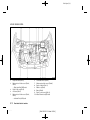
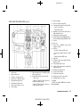
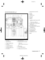
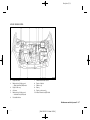
HR12DE ENGINE MODEL
GUID-EEE0B27B-AFE5-494C-8F7A-24BC07449160
JVC0452X
1.
2.
3.
4.
5.
Engine drive belts (P.8-16)
Brake and clutch* fluid reservoir (P.8-19,
P.8-20)
— Right-Hand Drive (RHD) model
Engine oil filler cap (P.8-11)
Air cleaner (P.8-21)
Brake and clutch* fluid reservoir (P.8-19,
P.8-20)
— Left-Hand Drive (LHD) model
0-16
Condition:
6.
7.
8.
9.
10.
11.
Fuse/fusible link box (P.8-27)
Window washer fluid reservoir (P.8-23)
Engine oil dipstick (P.8-11)
Radiator cap (P.8-9)
Battery (P.8-24)
Engine coolant reservoir (P.8-10)
*: For Manual Transmission (MT) Model
Illustrated table of contents
[ Edit: 2013/ 2/ 25 Model: K13-A ]
Black plate (21,1)
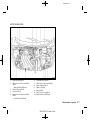
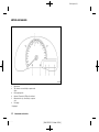
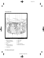
HR15DE ENGINE MODEL
GUID-BE6F299A-3379-4686-A8D8-F56ABA3A72F6
JVC0118X
1.
2.
3.
4.
5.
Engine drive belts (P.8-16)
Brake and clutch* fluid reservoir (P.8-19,
P.8-20)
— Right-Hand Drive (RHD) model
Engine oil filler cap (P.8-11)
Air cleaner (P.8-21)
Brake and clutch* fluid reservoir (P.8-19,
P.8-20)
— Left-Hand Drive (LHD) model
6.
7.
8.
9.
10.
11.
Fuse/fusible link box (P.8-27)
Window washer fluid reservoir (P.8-23)
Engine oil dipstick (P.8-11)
Radiator cap (P.8-9)
Battery (P.8-24)
Engine coolant reservoir (P.8-10)
*: For Manual Transmission (MT) Model
Illustrated table of contents
Condition:
[ Edit: 2013/ 2/ 25 Model: K13-A ]
0-17
Black plate (22,1)
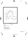
K9K ENGINE MODEL
GUID-8CE2311C-63B0-4636-A916-9EC2BD9653CF
SDI2711
1.
2.
3.
4.
5.
6.
7.
8.
Brake and clutch fluid reservoir (P.8-19, P.8-20)
Air cleaner (P.8-21)
Fuse/Fusible link holders (P.8-27)
Priming pump (P.8-16)
Window washer fluid reservoir (P.8-23)
Engine drive belts (P.8-16)
Engine oil filler cap (P.8-11)
Engine oil dipstick (P.8-11)
0-18
Condition:
9.
10.
Engine coolant reservoir (P.8-10)
— Vehicle overheat (P.6-11)
Battery (P.8-24)
Illustrated table of contents
[ Edit: 2013/ 2/ 25 Model: K13-A ]
Black plate (23,1)
1 Safety — seats, seat belts and supplemental
restraint system
Seats ...........................................................................................................
....
1-2
Front seats ..........................................................................................
....
1-2
Rear seats ...........................................................................................
....
1-4
Head restraints (if equipped) .........................................................
....
1-5
Armrest (if equipped) .......................................................................
....
1-6
Seat belts ..................................................................................................
....
1-7
Precautions on seat belt usage ....
.................................................... 1-7
Child safety .........................................................................................
....
1-8
Pregnant women ...............................................................................
....
1-9
Injured persons ..................................................................................
....
1-9
Center mark on seat belts ..............................................................
....
1-9
Three-point type seat belts ............................................................
....
1-9
Two-point type seat belts (if equipped) ...................................
....
1-12
Seat belt maintenance ..................................................................
....
1-13
Condition:
Child restraints .....................................................................................
....
Precautions on child restraint usage ......................................
....
Universal child restraints for front seat and rear seats
(for Europe and Ukraine) ...........................................................
....
ISOFIX child restraint system (if equipped) .........................
....
Child restraint anchorage (if equipped) ....
................................
Child restraint installation using ISOFIX ................................
....
Child restraint installation using seat belt .............................
....
Supplemental Restraint System (SRS) (if equipped) ................
....
Precautions on Supplemental Restraint System (SRS) ....
....
Supplemental air bag systems .................................................
....
Pre-tensioner seat belt system (if equipped) .......................
....
Repair and replacement procedure ........................................
....
[ Edit: 2013/ 2/ 25 Model: K13-A ]
1-13
1-13
1-14
1-17
1-18
1-19
1-21
1-25
1-25
1-29
1-31
1-32
Black plate (24,1)
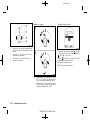
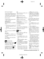
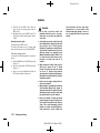
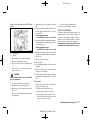
SEATS
GUID-0436B542-879E-4ABF-B2D7-322787F22D25
SSS0133A
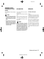
WARNING:
.
.
Do not drive and/or ride in the vehicle with
the seatback reclined. This can be dangerous. The shoulder belt will not be properly
against the body. In an accident, you and
your passengers could be thrown into the
shoulder belt and receive neck or other
serious injuries. You and your passengers
could also slide under the lap belt and
receive serious injuries.
For the most effective protection while the
vehicle is in motion, the seatback should be
upright. Always sit well back in the seat and
adjust the seat belt properly. (See “Seat
belts” (P.1-7).)
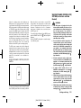
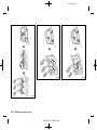
FRONT SEATS
GUID-4D1E7B4E-F45E-48AA-B4C0-016C3D114635
WARNING:
Do not adjust the driver’s seat while driving so
that full attention may be given to vehicle
operation.
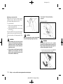
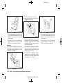
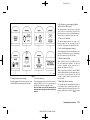
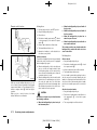
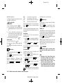
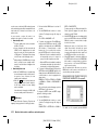
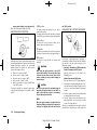
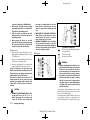
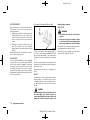
Manual seat adjustment
GUID-A841D004-994E-4CE4-9B43-88401CB148B9
WARNING:
After adjusting a seat, gently shake the seat to
confirm that the seat is locked securely. If the
seat is not locked securely, it may move
suddenly and could cause the loss of control of
the vehicle.
CAUTION:
When adjusting the seat positions, be sure not
to contact any moving parts to avoid possible
injuries and/or damages.
1-2
Condition:
Safety — seats, seat belts and supplemental restraint system
[ Edit: 2013/ 2/ 25 Model: K13-A ]
Black plate (25,1)
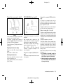
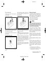
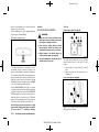
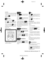
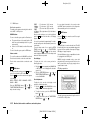
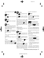
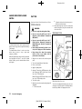
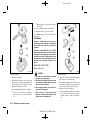
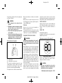
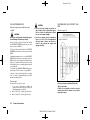
* will illuminate when low
. The indicator light 3
or high is selected.
3.
To turn off the heater, return the switch to the level
position. Make sure the indicator light turns off.
The heater is controlled by a thermostat, automatically
turning the heater on and off. The indicator light will
remain on as long as the switch is on.
When the vehicle’s interior is warmed, or before you
leave the vehicle, be sure to turn off the switch.
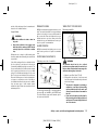
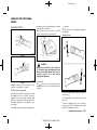
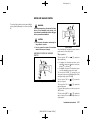
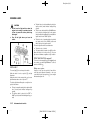
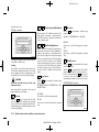
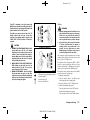
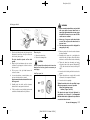
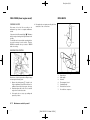
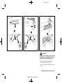
JVR0217X
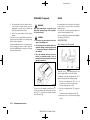
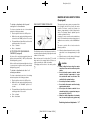
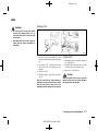
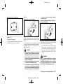
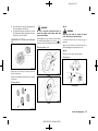
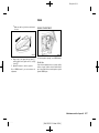
Forward and backward:
GUID-9E14C2E6-2E9C-4731-980B-C45B899B977B
1 .
1. Pull up the adjusting lever *
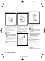
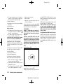
Heated seatsGUID-D36C2EDC-C2E9-421C-A77D-9679495487D3
(if equipped)
CAUTION:
.
The battery could run down if the seat heater
is operated while the engine is not running.
2.
Slide the seat to the desired position.
.
3.
Release the adjusting lever to lock the seat in
position.
Do not use the seat heater for extended
periods or when no one is using the seat.
.
Do not put anything on the seat which
insulates heat, such as a blanket, cushion,
seat cover, etc. Otherwise, the seat may
become overheated.
.
Do not place anything hard or heavy on the
seat or pierce it with a pin or similar object.
This may result in damage to the seat heater.
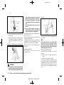
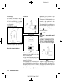
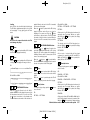
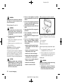
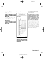
Reclining:
GUID-9E14C2E6-2E9C-4731-980B-C45B899B977B
2 .
1. Pull up the adjusting lever *
2.
Tilt the seatback to the desired position.
3.
Release the adjusting lever to lock the seatback in
position.
The reclining feature allows the adjustment of the
seatback for occupants of different sizes to help obtain
the proper seat belt fit. (See “Seat belts” (P.1-7).)
The seatback may be reclined to allow occupants to
rest when the vehicle is parked.
Seat lifter (if equipped):
GUID-9E14C2E6-2E9C-4731-980B-C45B899B977B
3 to adjust
Pull up or push down the adjusting lever *
the seat height until the desired position is achieved.
SIC2770
.
The seats can be warmed by built-in heaters. The
switches located on the center console can be
operated independently of each other.
Any liquid spilled on the heated seat should
be removed immediately with a dry cloth.
.
When cleaning the seat, never use gasoline,
thinner, or any similar materials.
1.
Start the engine.
.
2.
Select heat range.
. For high heat, push the HI (High) side of the
1 .
switch *
. For low heat, push the LO (Low) side of the
2 .
switch *
If any malfunctions are found or the heated
seat does not operate, turn the switch off
and have the system checked by a NISSAN
dealer.
Safety — seats, seat belts and supplemental restraint system
Condition:
[ Edit: 2013/ 2/ 25 Model: K13-A ]
1-3
Black plate (26,1)
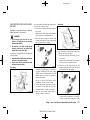
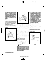
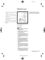
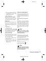
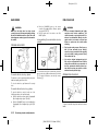
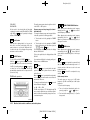
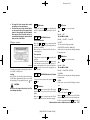
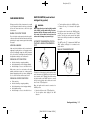
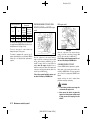
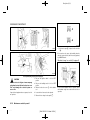
REAR SEATSGUID-437AE5ED-D0FB-48A6-AAC6-03CA1D7D09A0
Adjustment
Folding (Type A):
GUID-9E14C2E6-2E9C-4731-980B-C45B899B977B
GUID-D2DC58C7-3096-4AFC-BECC-96E4D8B84335
Do not fold down the rear seats when
occupants are in the rear seat area or any
luggage is on the rear seats.
.
Properly secure all luggage to help prevent it
from sliding or shifting. Do not place luggage higher than the seatbacks.
.
*
Never allow anyone to ride in the luggage
area or on the rear seats when they are in
the fold-down position. Use of these areas
by passengers without proper restraints
could result in serious injury in an accident
or sudden stop.
.
SSS0789
1.
Store the seat belts in the proper position. (See
“Three-point type seat belts” (P.1-9).)
2.
Pull the knob to fold the seatback down.
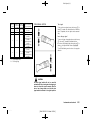
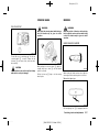
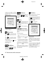
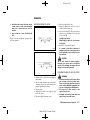
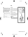
Passing the seat belt through the path (if equipped):
JVR0006X
CAUTION:
.
Condition:
.
After returning the rear seatback to its
original position, pass the seat belt through
the path A .
.
When operating the seatback, be careful not
to scratch or damage the seat belt.
*
When returning the seatbacks to the upright
position, be certain they are completely
secured in the latched position. If they are
not completely secured, passengers may be
injured in an accident or sudden stop.
1-4
When loading the luggage in the luggage
room, be careful not to scratch or damage
the seat belt.
If the rear seatback needs to be folded without
passing the seat belt through the path A , be
sure to observe the following items.
WARNING:
.
.
Fold down the rear seatback with the rear
center seat belt passed through the path A
on the seatback.
*
Safety — seats, seat belts and supplemental restraint system
[ Edit: 2013/ 2/ 25 Model: K13-A ]
Black plate (27,1)
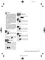
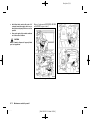
Folding (Type B):
GUID-9E14C2E6-2E9C-4731-980B-C45B899B977B
removed for any reason.
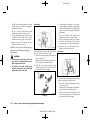
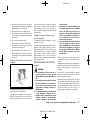
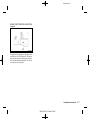
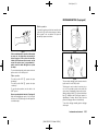
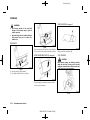
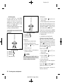
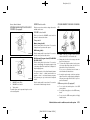
HEAD RESTRAINTS
(if equipped)
GUID-11A4B2B7-3A2F-4541-97C6-81111CF51199
JVR0007X
SSS0287
1.
Secure the seat belt on the clip.
2.
1 and fold the seatback down.
Pull up the knob *
3.
2 and lift the rear of the seat
Pull the strap *
cushion and the seatback.
WARNING:
.
Securing of the GUID-9E14C2E6-2E9C-4731-980B-C45B899B977B
folded rear seat (if equipped):
.
1 from the anchor on the
Remove the hook *
underside of the cushion.
2.
2 on the stalk as illustrated.
Secure the hook *
Do not fold down the rear seats when
occupants are in the rear seat area or any
luggage is on the rear seats.
.
Properly secure all luggage to help prevent it
from sliding or shifting. Do not place luggage higher than the seatbacks.
.
When returning the seatbacks to the upright
position, be certain they are completely
secured in the latched position. If they are
not completely secured, passengers may be
injured in an accident or sudden stop.
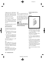
.
Head restraints should be adjusted properly
as they may provide significant protection
against whiplash injury. Always replace and
adjust them properly if they have been
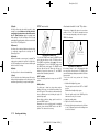
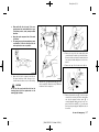
JVR0008X
1.
Never allow anyone to ride in the luggage
area or on the rear seats when they are in
the fold-down position. Use of these areas
by passengers without proper restraints
could result in serious injury in an accident
or sudden stop.
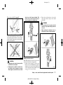
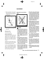
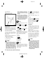
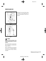
WARNING:
Do not drive and/or ride in the vehicle with the
head restraint removed. This can be dangerous.
Head restraints should be adjusted properly as
they may provide significant protection against
injury in an accident. Check the height after
someone else uses the seat.
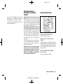
The proper adjustment of the head restraint is as
illustrated.
Adjust the head restraint so that the head restraint’s
center is level with the center of the ears.
Safety — seats, seat belts and supplemental restraint system
Condition:
[ Edit: 2013/ 2/ 25 Model: K13-A ]
1-5
Black plate (28,1)
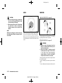
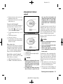
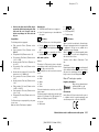
Adjustment
GUID-D2BCC152-0C29-4A82-9C64-EAADE1FB59C4
ARMREST (if GUID-71B3306C-F0A6-4C46-A2E7-9CAF89BBB64F
equipped)
Front
GUID-B38464E9-F919-461C-89AD-A1F686A7B4F3
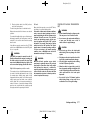
SSS0288
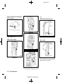
1.
Pull up the head restraint to raise to the proper
position.
2.
1 and push down the
Push in the lock knob *
head restraint to lower to the proper position.
SSS0970
Pull the armrest down until it is horizontal.
The rear head restraint (if equipped) should only be
used in the notched stem positions. The lowest head
restraint position is the stowed position.
1-6
Condition:
Safety — seats, seat belts and supplemental restraint system
[ Edit: 2013/ 2/ 25 Model: K13-A ]
Black plate (29,1)
SEAT BELTS
GUID-2EFFD13E-EFC3-484F-A5C7-BF2B9C98523D
PRECAUTIONS
ON SEAT BELT USAGE
GUID-71F040D1-F941-48AD-8BEC-D377E168D168
If you are wearing the seat belt properly adjusted and
sitting upright and well back in the seat, chances of
being injured or killed in an accident and/or the severity
of injury may be greatly reduced. NISSAN strongly
encourages you and all of your passengers to buckle
up every time you drive, even if your seating position
includes the supplemental air bag systems.
SSS0134A
SSS0136A
SSS0014
SSS0016
Safety — seats, seat belts and supplemental restraint system
Condition:
[ Edit: 2013/ 2/ 25 Model: K13-A ]
1-7
Black plate (30,1)
WARNING:
.
Seatbelts are designed to bear upon the
bony structure of the body, and should be
worn low across the front of the pelvis or the
pelvis, chest and shoulders, as applicable;
wearing the lap section of the belt across
the abdominal area must be avoided. Serious injury may occur if a seat belt is not
worn properly.
.
Position the lap belt as low and snug as
possible around the hips, not the waist. A
lap belt worn too high could increase the
risk of internal injuries in an accident.
.
Do not allow more than one person to use
the same seat belt. Each belt assembly must
only be used by one occupant; it is dangerous to put a belt around a child being carried
on the occupant’s lap.
.
Never carry more people in the vehicle than
there are seat belts.
.
Never wear seat belts inside out. Belts
should not be worn with straps twisted.
Doing so may reduce their effectiveness.
.
Seatbelts should be adjusted as firmly as
possible, consistent with comfort, to provide
the protection for which they have been
designed. A slack belt will greatly reduce the
protection afforded to the wearer.
.
Every person who drives or rides in this
vehicle should use a seat belt at all times.
Children should be properly restrained in the
rear seat and, if appropriate, in a child
restraint system.
1-8
Condition:
.
.
.
.
.
Do not run the belt behind your back or
under your arm. Always route the shoulder
belt over your shoulder and across your
chest. The belt should be away from your
face and neck, but not falling off your
shoulder. Serious injury may occur if a seat
belt is not worn properly.
No modifications or additions should be
made by the user which will either prevent
the seat belt adjusting devices from operating to remove slack, or prevent the seat belt
assembly from being adjusted to remove
slack.
Care should be taken to avoid contamination of the webbing with polishes, oils and
chemicals, and particularly battery acid.
Cleaning may safely be carried out using
mild soap and water. The belt should be
replaced if webbing becomes frayed, contaminated or damaged.
It is essential to replace the entire assembly
after it has been worn in a severe impact
even if damage to the assembly is not
obvious.
All seat belt assemblies including retractors
and attaching hardware should be inspected
after any collision by a NISSAN dealer. It is
essential to replace the entire assembly
after it has been worn in a severe impact
even if damage to the assembly is not
obvious. NISSAN recommends that all seat
belt assemblies in use during a collision be
replaced unless the collision was minor and
the belts show no damage and continue to
operate properly.
Safety — seats, seat belts and supplemental restraint system
[ Edit: 2013/ 2/ 25 Model: K13-A ]
.
Seat belt assemblies not in use during a
collision should also be inspected and, when
necessary, replaced if either damage or
improper operation is noted.
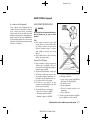
CHILD SAFETY
GUID-0EDF4D59-9339-4F34-8CC3-5C059CD8A308
WARNING:
.
Infants and children need special protection.
The vehicle’s seat belts may not fit them
properly. The shoulder belt may come too
close to the face or neck. The lap belt may
not fit over their small hipbones. In an
accident, an improperly fitted seat belt could
cause serious or fatal injury.
.
Always use an appropriate child restraint
system.
Children need adults to help protect them. They need
to be properly restrained. The proper restraint depends
on the child’s size.
Infants and small
children
GUID-F874539D-BF07-4E30-9724-A1BBD4664E5F
SSS0099
NISSAN recommends that infants and small children
be seated in a child restraint system. You should
choose a child restraint system that fits your vehicle
Black plate (31,1)
and the child, and always follow the manufacturer’s
instructions for installation and use.
Large childrenGUID-82E17BFE-8C77-4F84-8B5D-5C9ECF85DB40
WARNING:
.
Never allow children to stand or kneel on
any seats.
.
Never allow children in the luggage area
while the vehicle is moving. A child could be
seriously injured in an accident or sudden
stop.
Children who are too large for a child restraint system
should be seated and restrained by the seat belts that
are provided.
If the child’s seating position has a shoulder belt that
fits close to the face or neck, the use of a booster seat
(commercially available) may help overcome this. The
booster seat should raise the child so that the shoulder
belt is properly positioned across the top, middle
portion of the shoulder and the lap belt is low on the
hips. The booster seat should also fit the vehicle seat.
Once the child has grown so that the shoulder belt is
no longer on or near the face or neck of the child, use
the shoulder belt without the booster seat. In addition,
there are many types of child restraint systems
available for larger children that should be used for
maximum protection.
PREGNANT WOMEN
GUID-2934E8FD-892B-48B9-BF5D-7F4D8806C946
THREE-POINTGUID-587D3870-B384-4ED3-9B46-1A5F84E2E683
TYPE SEAT BELTS
NISSAN recommends that pregnant women use seat
belts. The seat belt should be worn snug, and always
position the lap belt as low as possible around the
hips, not the waist. Place the shoulder belt over your
shoulder and across your chest. Never run the lap/
shoulder belt over your abdominal area. Contact your
doctor for specific recommendations.
Fastening seatGUID-37885057-A75F-446F-839F-6D4B36780C01
belts
INJURED PERSONS
GUID-3DEC69F2-9359-473C-A918-01CCDE818F3C
NISSAN recommends that injured persons use seat
belts. Contact your doctor for specific recommendations.
SSS0292
CENTER MARK
ON SEAT BELTS
GUID-AE7303B6-E2B9-47FF-B56E-1DA57461158F
Selecting correct
set of seat belts
GUID-81AE2CC2-41C3-4ABA-BC06-EC384336CF2C
WARNING:
The seatback should not be in a reclined
position any more than needed for comfort. Seat
belts are most effective when the passenger sits
well back and straight up in the seat.
SSS0616
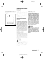
A or both the buckle and
The center seat belt buckle *
B are identified by the CENTER mark.
the tongue *
The center seat belt tongue can be fastened only into
the center seat belt buckle.
1.
Adjust the seat. (See “Seats” (P.1-2).)
2.
Slowly pull the seat belt out of the retractor and
insert the tongue into the buckle until you hear and
feel the latch engage.
. The retractor is designed to lock during a
sudden stop or on impact. A slow pulling
motion permits the seat belt to move, and
allows you some freedom of movement in
the seat.
. If the seat belt cannot be pulled from its
fully retracted position, firmly pull the belt
and release it. Then smoothly pull the belt
out of the retractor.
Safety — seats, seat belts and supplemental restraint system
Condition:
[ Edit: 2013/ 2/ 25 Model: K13-A ]
1-9
Black plate (32,1)
entire restraint system and increase the
chance or severity of injury in an accident.
SSS0467
3.
Position the lap belt portion low and snug on the
hips as shown.
4.
Pull the shoulder belt portion toward the retractor
to take up extra slack. Be sure the shoulder belt is
routed over your shoulder and is snug across your
chest.
Shoulder belt height
adjustment (if equipped)
GUID-83062340-ACA2-43E8-806F-AAAB9342A42E
.
The shoulder belt should rest on the middle
of the shoulder. It must not rest against the
neck.
.
Be sure that the seat belt is not twisted in
any way.
.
Be sure that the shoulder belt anchor is
secured by trying to move the shoulder belt
anchor up and down after adjustment.
Belt hook
The shoulder belt anchor height should be adjusted to
the position best for you.
SSS1090
The belt should be away from your face and neck, but
not falling off your shoulder.
Hook the seat belt at the belt hook when folding down
the rear seat.
1 and move the
To adjust, pull the release button *
2 , so that
shoulder belt anchor to the proper position *
the belt passes over the center of the shoulder.
NOTE:
Release the button to lock the shoulder belt anchor
into position.
Unfastening seat
belts
GUID-3C11CC3A-CF3D-4558-A2AD-A2E7FFF41769
Push the button on the buckle. The seat belt
automatically retracts.
Before folding down the rear seatback, make
sure that the seat belt tongue is securely
fastened to the belt clip. Also, make sure that
the seat belt does not get caught in the seatback
when folding down the rear seat.
Checking seatGUID-EE4C779F-FDBB-4398-A2DB-5182A125ACA4
belt operation
Seat belt retractors are designed to lock seat belt
movement:
.
When the seat belt is pulled quickly from the
retractor.
. When the vehicle slows down rapidly.
To increase your confidence in the seat belts, check
the operation by grasping the shoulder belt and pulling
forward quickly. The retractor should lock and restrict
further belt movement. If the retractor does not lock
during this check, contact a NISSAN dealer immediately.
SSS0351A
WARNING:
.
The shoulder belt anchor height should be
adjusted to the position best for you. Failure
to do so may reduce the effectiveness of the
1-10
Condition:
GUID-EEF454FF-D065-493D-9B95-9ED80C2F30CA
Safety — seats, seat belts and supplemental restraint system
[ Edit: 2013/ 2/ 25 Model: K13-A ]
Black plate (33,1)
Rear center seat
belt (if equipped)
GUID-FF1750A3-673C-439B-BE92-3FB160B83584
only the seat belt tongue attached. This
could result in serious personal injury in
case of an accident or a sudden stop.
2.
Retract the seat belt and store the seat belt
tongue and connector tongue on the stowed
3 .
position *
.
Do not unfasten the rear center seat belt
connector except when folding down the
rear seat.
.
When returning the seatback, be sure to
attach the rear center seat belt connector.
WARNING:
SSS0391
1
The rear center seat belt has a connector tongue *
2 . Both the connector tongue
and a seat belt tongue *
and the seat belt tongue must be securely latched for
proper seat belt operation.
JVR0003X
SSS0241
WARNING:
.
Always fasten the connector tongue and the
seat belt in the order shown.
.
Always make sure both the connector tongue and the seat belt tongue are secured
when using the seat belt. Do not use it with
Stowing rear center
seat belt:
GUID-9E14C2E6-2E9C-4731-980B-C45B899B977B
When folding down the rear seat, the rear center seat
belt can be retracted into a stowed position.
1.
1 so that the seat
Hold the connector tongue *
belt does not retract suddenly when the tongue is
released from the connector buckle. Release the
connector tongue by inserting a suitable tool such
2 into the connector buckle.
as key *
JVR0004X
Safety — seats, seat belts and supplemental restraint system
Condition:
[ Edit: 2013/ 2/ 25 Model: K13-A ]
1-11
Black plate (34,1)
TWO-POINT TYPE SEAT BELTS (if
equipped)
GUID-2FB960F8-8B9C-45CE-BAE9-DE55ABB61FE5
Attaching rear center
seat belt:
GUID-9E14C2E6-2E9C-4731-980B-C45B899B977B
Always be sure the rear center seat belt connector
tongue and connector buckle are attached. Disconnect only when folding down the rear seat.
Fastening seatGUID-E896C968-617B-429B-94B3-487B6F28060F
belts
To connect the buckle:
1.
Pull the seat belt tongue and connector tongue
1 .
from the stowed position *
2.
Pull the seat belt and secure the connector buckle
2 .
until it clicks *
The center seat belt connector tongue can be attached
only into the rear center seat belt connector buckle.
To fasten the seat belt, see “Fastening seat belts” (P.19).
WARNING:
.
.
JVR0006X
CAUTION:
Make sure to wear the rear center seat belt with
the seat belt passing through the path A .
SSS0448
*
WARNING:
When attaching the rear center seat belt
connector, be certain that the seatbacks are
completely secured in the latched position
and the rear center seat belt connector is
completely secured.
The seatback should not be in a reclined
position any more than needed for comfort. Seat
belts are most effective when the passenger sits
well back and straight up in the seat.
If the rear center seat belt connector and the
seatbacks are not secured in the correct
position, serious personal injury may result
in an accident or sudden stop.
1.
Insert the tongue into the buckle marked CENTER
until you hear and feel the latch engage.
SSS0541
1-12
Condition:
Safety — seats, seat belts and supplemental restraint system
[ Edit: 2013/ 2/ 25 Model: K13-A ]
Black plate (35,1)
CHILD RESTRAINTS
2.
Adjust the seat belt length. To shorten, hold the
1 .
tongue and pull the upper belt as illustrated *
To lengthen, hold the tongue and pull the under
2 .
belt as illustrated *
GUID-D1B3B6D7-C7D7-4753-91EE-75DF2C345A8F
PRECAUTIONS ON CHILD RESTRAINT
USAGE
GUID-84539F71-07B4-4992-B051-160D792D0591
.
Child restraint systems specially designed
for infants and small children are available
from several manufacturers. When selecting
any child restraint systems, place your child
in the child restraint system and check the
various adjustments to be sure that the child
restraint system is compatible with your
child. Always follow the manufacturer’s instructions for installation and use.
.
NISSAN recommends that the child restraint
system be installed in the rear seat. According to accident statistics, children are safer
when properly restrained in the rear seat
rather than in the front seat.
.
Follow all of the child restraint system
manufacturer’s instructions for installation
and use. When purchasing a child restraint
system, be sure to select one which will fit
your child and vehicle. It may not be possible
to properly install some types of child
restraint systems in your vehicle.
.
For a front-facing child restraint system,
check to make sure the shoulder belt does
not fit close to child’s face or neck. If it does,
put the shoulder belt behind the child
restraint system.
.
Never install a rear-facing child restraint
system in the front seat. An inflating supplemental front-impact air bag could seriously
injure or kill your child. A rear-facing child
restraint system must only be used in the
rear seat.
.
Adjustable seatbacks should be positioned
to fit a child restraint system, but as upright
as possible.
SSS0099
SSS0450
3.
Position the lap belt portion low and snug on the
hips as shown.
WARNING:
.
Unfastening seat
belts
GUID-83362DBC-05D2-4411-A0F9-92FAFF26E5F2
Push the button on the buckle.
SEAT BELT MAINTENANCE
GUID-3C96CF89-85AF-428C-8071-11B0DAEFED38
Periodically check that the seat belt and all the metal
components, such as buckles, tongues, retractors,
flexible wires and anchors, work properly. If loose parts,
deterioration, cuts or other damage on the seat belt
webbing is found, the entire seat belt assembly should
be replaced.
.
If dirt builds up in the shoulder belt guide of the seat
belt anchors, the seat belts may retract slowly. Wipe
the shoulder belt guide with a clean, dry cloth.
To clean the seat belt webbing, apply a mild soap
solution or any solution recommended for cleaning
upholstery or carpet. Then wipe with a cloth and allow
the seat belts to dry in the shade. Do not allow the seat
belts to retract until they are completely dry.
.
Infants and small children should never be
carried on your lap. It is not possible for even
the strongest adult to resist the forces of a
severe accident. The child could be crushed
between the adult and parts of the vehicle.
Also, it is dangerous to put a seat belt
around a child being carried on the occupant’s lap.
Infants and children need special protection.
The vehicle’s seat belts may not fit them
properly. The shoulder belt may come too
close to the face or neck. The lap belt may
not fit over their small hip bones. In an
accident, an improperly fitting seat belt
could cause serious or fatal injury.
Infants and small children should always be
placed in an appropriate child restraint
system while riding in the vehicle. Failure
to use a child restraint system can result in
serious injury or death.
Safety — seats, seat belts and supplemental restraint system
Condition:
[ Edit: 2013/ 2/ 25 Model: K13-A ]
1-13
Black plate (36,1)
.
.
If the seat belt in the position where a child
restraint system is installed requires a locking clip and if it is not used, injuries could
result from a child restraint system tipping
over during normal vehicle braking or cornering.
After attaching a child restraint system, test
it before you place the child in it. Tilt it from
side to side. Try to tug it forward and check if
it is held securely in place. The child restraint
system should not move more than 25 mm (1
in). If the restraint is not secure, tighten the
belt as necessary, or install the restraint in
another seat and test it again.
.
Check the child restraint system in your
vehicle to be sure that it is compatible with
the vehicle’s seat belt system.
.
If a child restraint system is not anchored
properly, the risk of a child being injured in a
collision or a sudden stop greatly increases.
.
Improper use of a child restraint system can
increase the risk or severity of injury for both
the child and other occupants in the vehicle.
.
Always use an appropriate child restraint
system. An improperly installed child restraint system could lead to serious injury
or death in an accident.
.
installation and use. In addition, there are many types
of child restraint systems available for larger children
that should be used for maximum protection.
CAUTION:
Remember that a child restraint system left in a
closed vehicle can become very hot. Check the
seating surface and buckles before placing your
child in a child restraint system.
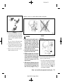
UNIVERSAL CHILD RESTRAINTS FOR
FRONT SEAT AND REAR SEATS (for Europe
and Ukraine) GUID-D5C9B1DE-3E97-4308-9494-C83310B63EDB
When selecting any child restraint, keep the following
points in mind:
.
.
.
.
Choose a child restraint that complies with the
latest European safety standard, ECE Regulation
44.04.
Place your child in the child restraint and check
the various adjustments to be sure the child
restraint is compatible with your child. Always
follow all of the recommended procedures.
Check the child restraint in your vehicle to be sure
it is compatible with vehicle’s seat belt system.
Refer to the tables later in this section for a list of
the recommended fitment positions and the
approved child restraints for your vehicle.
When the child restraint system is not in use,
keep it secured with the ISOFIX child
restraint system (if equipped) or a seat belt
to prevent it from being thrown around in
case of a sudden stop or accident.
NISSAN recommends that infants and small children
be seated in a child restraint system. You should
choose a child restraint system that fits your vehicle
and always follow the manufacturer’s instructions for
1-14
Condition:
Safety — seats, seat belts and supplemental restraint system
[ Edit: 2013/ 2/ 25 Model: K13-A ]
Black plate (37,1)
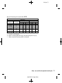
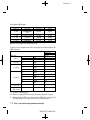
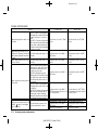
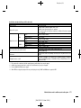
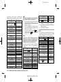
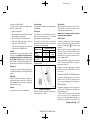
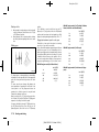
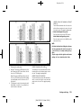
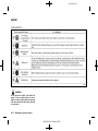
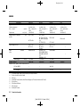
Approved child restraint positions (models without ISOFIX)
GUID-4B47FC71-C923-4A4B-BA9B-60CBF9C83F5E
Seating position
Weight group
Front passenger
0 (<10 kg)
Rear (Single folding)
Rear (Tumble)
Right
Centre
Left
Right
Centre
Left
X
L
L
L
L
L
L
0 +(<13 kg)
X
L
L
L
L
L
L
I (9 to 18 kg)
UF
L
X
L
L
L
X
II (15 to 25 kg)
UF
L
L
L
L
L
III (22 to 36 kg)
UF
L
L
L
L
L
L
L
X:
Not suitable for child restraint system.
UF: Suitable for forward-facing (FWF) universal category child restraint system approved for this group.
L:
Suitable for the particular child restraints provided in the following table.
Safety — seats, seat belts and supplemental restraint system
Condition:
[ Edit: 2013/ 2/ 25 Model: K13-A ]
1-15
Black plate (38,1)
List of approved child restraints
GUID-070BD51F-02D9-4526-A915-CE48597D6CFA
Weight group
Name of CRS
Facing position
Category
0 to 13 kg
Britax/RÖMER BABYSAFE
Rear-facing
Universal
9 to 18 kg
Britax/RÖMER DUO plus
Front-facing
Universal
9 to 18 kg
Fair GO/1S
Front-facing
15 to 36 kg
Britax/RÖMER Kid
Front-facing
Universal
Universal
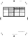
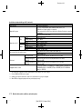
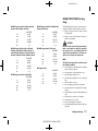
Approved child restraint positions (models with ISOFIX)
GUID-16DC236E-5C84-4D51-AAF9-693CBD62AC7C
The following restrictions are applied when using child restraints varying by infants weight and installation position
(ISOFIX child restraint):
Seating position
Rear outer
Weight group
F
ISO/L1
X
G
ISO/L2
X
E
ISO/R1
X
E
ISO/R1
X
D
ISO/R2
X
C
ISO/R3
IL
D
ISO/R2
X
C
ISO/R3
IL
B
ISO/F2
IUF
B1
ISO/F2X
IUF, IL
A
ISO/F3
IUF
II (15 to 25 kg)
-
X
III (22 to 36 kg)
-
X
Carry-cot
0 (<10 kg)
0+ (<13 kg)
I (9 to 18 kg)
X:
Not suitable for child restraint system.
IUF: Suitable for forward-facing (FWF) universal category child restraint system approved for this group.
IL: Suitable for the particular ISOFIX category child restraint systems (CRS) provided in the following table.
These ISOFIX CRS are those of the specific vehicle, restricted or semi-universal categories.
1-16
Condition:
Safety — seats, seat belts and supplemental restraint system
[ Edit: 2013/ 2/ 25 Model: K13-A ]
Black plate (39,1)
List of approved child restraints
WARNING:
GUID-12703704-BED5-4EAC-AE9B-9CDEEF14A8EF
Weight group
Size class
Name of CRS
Fixture of CRS
Facing position
Category
0 to 18 kg
C
Fair GO/1S
ISO/R3 support
frame (type A)
Rear-facing
Semi-Universal
9 to 18 kg
B1
Britax/RÖMER
DUO plus
ISO/F2X top
tether
Front-facing*
Universal
*Front facing: from 2 years only with headrest.
In vehicles equipped with a side air bag system,
do not let any infants or small children sit in the
front passenger’s seat as the air bag may cause
serious injury in case of deployment during a
collision.
NOTE:
Child restraints approved to ECE Regulation NO.
44.04 are clearly marked with the categories
such as Universal, Semi-universal or ISOFIX.
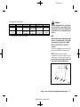
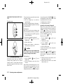
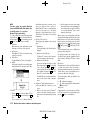
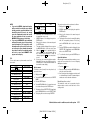
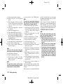
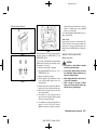
ISOFIX CHILD RESTRAINT SYSTEM (if
equipped) GUID-7DAC36F2-E2B9-493B-B926-2FCB2F3D83C1
Your vehicle is equipped with special anchor points
that are used with ISOFIX child restraint systems.
ISOFIX lower GUID-A8304ACD-7914-45BF-924C-ABC30FC91996
anchor point locations
The ISOFIX anchor points are provided to install child
restraints in the rear outboard seating positions only.
Do not attempt to install a child restraint in the
center position using the ISOFIX anchors.
SSS1046
ISOFIX label location
Safety — seats, seat belts and supplemental restraint system
Condition:
[ Edit: 2013/ 2/ 25 Model: K13-A ]
1-17
Black plate (40,1)
ISOFIX child restraints generally require the use of a
top tether strap or other anti-rotation devices such as
support legs. When installing ISOFIX child restraints,
carefully read and follow the instructions in this manual
and those supplied with the child restraints. (See
“Child restraint installation using ISOFIX” (P.1-19).)
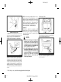
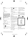
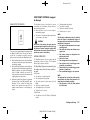
Anchorage location
GUID-B23FAAE8-F2E4-4ACA-9459-2381DF4D41E9
CHILD RESTRAINT ANCHORAGE (if
equipped) GUID-9CBC9A3C-37A6-490D-BE0C-8F53A4EF3D3A
SSS0637
ISOFIX lower anchor location
The ISOFIX anchors are located at the rear of the seat
cushion near the seatback. A label is attached to the
seatback to help you locate the ISOFIX anchors.
ISOFIX child restraint
anchor attachments
GUID-9DE17E3D-A48B-4832-8C7E-D39C3F2B3236
SSS0644
Anchor attachment
ISOFIX child restraints include two rigid attachments
that can be connected to two anchors located in the
seat. With this system, you do not have to use a vehicle
seat belt to secure the child restraint. Check your child
restraint for a label stating that it is compatible with the
ISOFIX child restraints. This information may also be in
the instructions provided by the child restraint manufacturer.
1-18
Condition:
Your vehicle is designed to accommodate a child
restraint system on the rear seat. When installing a
child restraint system, carefully read and follow the
instructions in this manual and those supplied with the
child restraint system.
WARNING:
.
Child restraint anchorages are designed to
withstand only those loads imposed by
correctly fitted child restraints. Under no
circumstances are they to be used for adult
seat belts, harnesses or for attaching other
items or equipment to the vehicle.
.
The child restraint top tether strap may be
damaged by contact with the cargo cover or
items in the luggage area. Remove the cargo
cover from the vehicle or secure it and any
luggage. Your child could be seriously
injured or killed in a collision if the top
tether strap is damaged.
Safety — seats, seat belts and supplemental restraint system
[ Edit: 2013/ 2/ 25 Model: K13-A ]
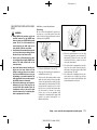
JVR0001X
The anchor points are located on the seat behind the
rear seats outboard seating positions.
JVR0009X
For Australia and New Zealand
The center anchorage (if equipped) is located on the
back door opening.
Black plate (41,1)
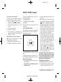
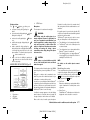
CHILD RESTRAINT INSTALLATION USING
ISOFIX
GUID-BCBDE462-22A7-4AF3-BE55-6633F83BDD27
WARNING:
.
Attach ISOFIX child restraints only at the
specified locations. For the ISOFIX lower
anchor locations, see “ISOFIX child restraint
system” (P.1-17). If a child restraint is not
secured properly, your child could be seriously injured or killed in an accident.
.
Do not install child restraints that require the
use of a top tether strap to seating positions
that do not have a top tether anchor.
.
Do not secure a child restraint in the center
rear seating position using the ISOFIX lower
anchors. The child restraint will not be
secured properly.
.
Inspect the lower anchors by inserting your
fingers into the lower anchor area and
feeling to make sure there are no obstructions over the ISOFIX anchors, such as seat
belt webbing or seat cushion material. The
child restraint will not be secured properly if
the ISOFIX anchors are obstructed.
.
Child restraint anchorages are designed to
withstand only those loads imposed by
correctly fitted child restraints. Under no
circumstance are they to be used for adult
seat belts, harnesses or for attaching other
items or equipment to the vehicle.
Installation on GUID-EBA567E6-B179-4045-AE2A-CE4765ED2602
rear outboard seats
Front-facing: GUID-9E14C2E6-2E9C-4731-980B-C45B899B977B
Be sure to follow the manufacturer’s instructions for
the proper use of your child restraint. Follow these
steps to install a front-facing child restraint on the rear
outboard seats using ISOFIX:
SSS0754A
Step 4
SSS0646A
4.
Shorten the rigid attachment to have the child
3
restraint firmly tightened; press downward *
4 firmly in the center of the child
and rearward *
restraint with your knee to compress the vehicle
seat cushion and seatback.
5.
If the child restraint is equipped with a top tether
strap, route the top tether strap and secure the
tether strap to the tether anchor point. (See “Child
restraint anchorage” (P.1-18).)
6.
If the child restraint is equipped with other antirotation devices such as support legs, use them
instead of the top tether strap following the child
restraint manufacturer’s instructions.
Steps 1 and 2
1.
1 .
Position the child restraint on the seat *
2.
Secure the child restraint anchor attachments to
2 .
the ISOFIX lower anchors *
3.
The back of the child restraint should be secured
against the vehicle seat back. If necessary, adjust
or remove the head restraint to obtain the correct
child restraint fit. (See “Head restraints” (P.1-5).) If
the head restraint is removed, store it in a secure
place. Be sure to install the head restraint when
the child restraint is removed. If the seating
position does not have an adjustable head
restraint and it is interfering with the proper child
restraint fit, try another seating position or a
different child restraint.
Safety — seats, seat belts and supplemental restraint system
Condition:
[ Edit: 2013/ 2/ 25 Model: K13-A ]
1-19
Black plate (42,1)
1.
1 .
Position the child restraint on the seat *
2.
Secure the child restraint anchor attachments to
2 .
the ISOFIX lower anchors *
SSS0755A
SSS0757A
Step 7
7.
8.
Step 6
Test the child restraint before you place the child
5 . Push the child restraint from side to side
in it *
and tug it forward to make sure that it is held
securely in place.
Check to make sure that the child restraint is
properly secured prior to each use. If the child
restraint is loose, repeat steps 3 through 7.
Rear-facing:
GUID-9E14C2E6-2E9C-4731-980B-C45B899B977B
Be sure to follow the manufacturer’s instructions for
the proper use of your child restraint. Follow these
steps to install a rear-facing child restraint on the rear
outboard seats using ISOFIX:
7.
Check to make sure that the child restraint is
properly secured prior to each use. If the child
restraint is loose, repeat steps 3 through 6.
SSS0756A
3.
Shorten the rigid attachment to have the child
3
restraint firmly tightened; press downward *
4 firmly in the center of the child
and rearward *
restraint with your hand to compress the vehicle
seat cushion and seatback.
4.
If the child restraint is equipped with a top tether
strap, route the top tether strap and secure the
tether strap to the tether anchor point. (See “Child
restraint anchorage” (P.1-18) .)
5.
If the child restraint is equipped with other antirotation devices such as support legs, use them
instead of the top tether strap following the child
restraint manufacturer’s instructions.
SSS0649A
Condition:
Test the child restraint before you place the child
5 . Push the child restraint from side to side
in it *
and tug it forward to make sure that it is held
securely in place.
Step 3
Steps 1 and 2
1-20
6.
Safety — seats, seat belts and supplemental restraint system
[ Edit: 2013/ 2/ 25 Model: K13-A ]
Black plate (43,1)
CHILD RESTRAINT INSTALLATION USING
SEAT BELT GUID-D2F6DA79-3BC2-497B-A19A-D27CCCA06FA2
Installation on rear outboard seats - seat belts
without automatic
locking mode
GUID-2745B2E8-E536-400E-AEB7-FCDE2FB2D5BB
If you must install a front-facing child restraint system
on the rear seat, follow these steps:
1.
The three-point type seat belt on your
vehicle is not equipped with an automatic
locking mode retractor.
.
The direction of the child restraint system
depends on the type of the child restraint
system and the size of the child.
Position the front-facing child restraint system on
the rear seat.
2.
Route the seat belt tongue through the child
restraint system and insert it into the buckle until
you hear and feel the latch engage.
SSS0375A
If you must install a rear-facing child restraint system
on the rear seat, follow these steps:
If your vehicle is equipped with rear seat adjustment,
note the following:
.
.
1.
Attach the child restraints after adjusting the
rear seats to the upright position.
Do not recline the rear seats with the child
restraints attached to them.
Front-facing:
GUID-9E14C2E6-2E9C-4731-980B-C45B899B977B
Always follow the child restraint system manufacturer’s instructions for installation and use.
WARNING:
.
Rear-facing:
Position the rear-facing child restraint system on
the rear seat.
Always follow the child restraint system manufacturer’s instructions for installation and use.
SSS0513
GUID-9E14C2E6-2E9C-4731-980B-C45B899B977B
To prevent slack in the lap belt, it is necessary to
secure the shoulder belt in place with a locking
A . Use the locking clip attached to the child
clip *
restraint system or one which is equivalent in
dimension and strength.
2.
Route the seat belt tongue through the child
restraint system and insert it into the buckle until
you hear and feel the latch engage.
Be sure to follow the child restraint system
manufacturer’s instructions for belt routing.
SSS0374A
3.
Test the child restraint system before you place
the child in it. Tilt it from side to side. Try to tug it
forward and check if it is held securely in place.
4.
Make sure that the child restraint system is
properly secured prior to each use.
SSS0513
To prevent slack in the lap belt, it is necessary to
secure the shoulder belt in place with a locking
Safety — seats, seat belts and supplemental restraint system
Condition:
[ Edit: 2013/ 2/ 25 Model: K13-A ]
1-21
Black plate (44,1)
A . Use the locking clip attached to the child
clip *
restraint system or one which is equivalent in
dimension and strength.
Front-facing:
GUID-9E14C2E6-2E9C-4731-980B-C45B899B977B
3.
Be sure to follow the child restraint system
manufacturer’s instructions for belt routing.
3.
Test the child restraint system before you place
the child in it. Tilt it from side to side. Try to tug it
forward and check if it is held securely in place.
4.
Make sure that the child restraint system is
properly secured prior to each use.
Installation on rear center seat (2-point type
seat belt)- seat belts without automatic
locking modeGUID-E8AB11EC-7449-4C6A-A48E-FD9CEBA5CE3B
WARNING:
.
The rear center two-point type seat belt on
your vehicle is not equipped with an automatic locking mode retractor.
.
The direction of the child restraint system
depends on the type of the child restraint
system and the size of the child.
To prevent slack in the lap belt, it is necessary to
A .
secure the lap belt in place with a locking clip *
Use the locking clip attached to the child restraint
system, or one which is equivalent in dimensions
and strength.
Be sure to follow the child restraint system
manufacturer’s instructions for belt routing.
4.
Test the child restraint system before you place
the child in it. Tilt it from side to side. Try to tug it
forward and check if it is held securely in place.
5.
Make sure that the child restraint system is
properly secured prior to each use.
SSS0512
If you must install a front-facing child restraint system
on the rear center seat, follow these steps:
1.
Rear-facing:
GUID-9E14C2E6-2E9C-4731-980B-C45B899B977B
Position the front-facing child restraint system on
the rear center seat.
Always follow the child restraint system manufacturer’s instructions for installation and use.
2.
Route the seat belt tongue through the child
restraint system and insert it into the buckle until
you hear and feel the latch engage.
SSS0514
If you must install a rear-facing child restraint system
on the rear center seat, follow these steps:
1.
Position the rear-facing child restraint system on
the rear center seat.
Always follow the child restraint system manufacturer’s instructions for installation and use.
SSS0513
Locking clip
1-22
Condition:
Safety — seats, seat belts and supplemental restraint system
[ Edit: 2013/ 2/ 25 Model: K13-A ]
2.
Route the seat belt tongue through the child
restraint system and insert it into the buckle until
you hear and feel the latch engage.
Black plate (45,1)
Installation on front seat - seat belts without automatic locking mode
GUID-48CF52C1-AED2-4536-89C6-01204BD1A763
SSS0513
Locking clip
3.
To prevent slack in the lap belt, it is necessary to
A .
secure the lap belt in place with a locking clip *
Use the locking clip attached to the child restraint
system, or one which is equivalent in dimensions
and strength.
SSS0300A
.
Never install a rear-facing child restraint on
the front passenger’s seat when the front
passenger’s air bag is equipped. Supplemental front-impact air bags inflate with
great force. A rear-facing child restraint
could be struck by the supplemental frontimpact air bags in an accident and could
seriously injure or kill your child.
.
Never install a child restraint system with a
top tether strap on the front seat.
.
NISSAN recommends that a child restraint
system be installed on the rear seat. However, if you must install a front-facing child
restraint system on the front passenger’s
seat, move the passenger’s seat to the
rearmost position.
Be sure to follow the child restraint system
manufacturer’s instructions for belt routing.
4.
Test the child restraint system before you place
the child in it. Tilt it from side to side. Try to tug it
forward and check if it is held securely in place.
5.
Make sure that the child restraint system is
properly secured prior to each use.
equipped.
WARNING:
.
Child restraints for infants must be used in
the rear-facing direction and therefore must
not be used on the front passenger’s seat
when the front passenger’s air bag is
Front-facing:
GUID-9E14C2E6-2E9C-4731-980B-C45B899B977B
SSS0627
If you must install a front-facing child restraint system
on the front seat, follow these steps:
1.
Turn off the front passenger’s air bag using the
front passenger air bag switch. (See “Supplemental air bag systems” (P.1-29)) Place the
ignition switch in the “ON” position and make
on the
sure that the front air bag status light
meter illuminates (if equipped).
Safety — seats, seat belts and supplemental restraint system
Condition:
[ Edit: 2013/ 2/ 25 Model: K13-A ]
1-23
Black plate (46,1)
2.
1 .
Move the seat to the rearmost position *
3.
Adjust the head restraint to its highest position
2 .
*
4.
Position the front-facing child restraint system on
the front passenger’s seat. It should be placed in
the front-facing direction only.
Always follow the child restraint system manufacturer’s instructions for installation and use.
6.
To prevent slack in the lap belt, it is necessary to
secure the shoulder belt in place with a locking
A . Use the locking clip attached to the child
clip *
restraint system, or one which is equivalent in
dimensions and strength.
Be sure to follow the child restraint system
manufacturer’s instructions for belt routing.
7.
Slide the seat forward so that the seat belt fully
tightens the child restraint system.
8.
Test the child restraint system before you place
the child in it. Tilt it from side to side. Try to tug it
forward and check if it is held securely in place.
9.
Make sure that the child restraint system is
properly secured prior to each use.
SSS0515
5.
Route the seat belt tongue through the child
restraint system and insert it into the buckle until
you hear and feel the latch engage.
SSS0513
Locking clip
1-24
Condition:
Safety — seats, seat belts and supplemental restraint system
[ Edit: 2013/ 2/ 25 Model: K13-A ]
Black plate (47,1)
SUPPLEMENTAL RESTRAINT
SYSTEM (SRS) (if equipped)
GUID-F6CA8394-1D04-4410-A5A8-2B14D2841181
PRECAUTIONS ON SUPPLEMENTAL RESTRAINT SYSTEM
(SRS)
GUID-749BA495-5B96-4CB1-8651-DA27C70844A3
This Supplemental Restraint System (SRS) section
contains important information concerning the driver’s
and passenger’s supplemental front-impact air bags.
Supplemental front-impact air bag system (if
equipped)
GUID-73246F1A-302B-4A23-AE5C-CFD64DB58165
This system can help cushion the impact force to the
head and chest area of the driver and/or front
passenger in certain frontal collisions. The supplemental front-impact air bag is designed to inflate on the
front where the vehicle is impacted.
Supplemental side-impact air bag system (if
equipped)
GUID-59B8B010-5D45-43A1-AEC8-E8AE2A43E094
should always be seated a suitable distance away from
the steering wheel. (See “Seat belts” (P.1-7).) The air
bags inflate quickly in order to help protect the
occupants. The force of the air bags inflating can
increase the risk of injury if the occupants are too close
to, or are against, the air bag modules during inflation.
The air bags will deflate quickly after deployment.
The SRS operates only when the ignition switch
is in the “ON” or “START” position.
When the ignition switch is in the “ON” position,
the SRS air bag warning light illuminates for
about 7 seconds and then turns off. This
indicates that the SRS is operational. (See
“SRS air bag warning light” (P.1-28).)
This system can help cushion the impact force to the
chest and pelvis areas of the driver and front
passenger in certain side-impact collisions. The
supplemental side-impact air bag is designed to inflate
on the side where the vehicle is impacted.
Supplemental curtain side-impact air bag
system (if equipped)
GUID-0EB7FC70-EFFC-4A87-BD48-55F59701D8F1
This system can help cushion the impact force to the
head of the driver and passengers in front and rear
outboard seating positions in certain side-impact
collisions. The supplemental curtain side-impact air
bag is designed to inflate on the side where the vehicle
is impacted.
The SRS is designed to supplement the accident
protection provided by the driver’s seat belt and is not
designed to substitute for it. The SRS can help save
lives and reduce serious injuries. However, inflating air
bags may cause abrasions or other injuries. Air bags
do not provide protection to the lower body. Seat belts
should always be correctly worn and the occupants
Safety — seats, seat belts and supplemental restraint system
Condition:
[ Edit: 2013/ 2/ 25 Model: K13-A ]
1-25
Black plate (48,1)
WARNING:
.
The supplemental front-impact air bags
ordinarily will not inflate in the event of a
side impact, rear impact, rollover, or lower
severity frontal collision. Always wear the
seat belts to help reduce the risk or severity
of injury in accidents.
.
The seat belts and the supplemental frontimpact air bags are most effective when you
are sitting well back and upright in the seat.
The front-impact air bags inflate with great
force. If you are unrestrained, leaning for-
1-26
Condition:
SSS0131A
SSS0006
SSS0132A
SSS0007
ward, sitting sideways, or out of position in
any way, you are at greater risk of injury or
death in an accident. You may also receive
serious or fatal injuries from the supplemental front-impact air bag if you are up
against it when it inflates. Always sit back
against the seatback and as far away as
practical from the steering wheel. Always
use the seat belts.
SSS0008
Safety — seats, seat belts and supplemental restraint system
[ Edit: 2013/ 2/ 25 Model: K13-A ]
Black plate (49,1)
WARNING:
.
Never let children ride unrestrained or
extend their hands or face out of the
window. Do not attempt to hold them in
your lap or arms. Some examples of dangerous riding positions are shown in the
illustrations.
.
Children may be severely injured or killed
when the air bags inflate if they are not
properly restrained.
.
Never install a rear-facing child restraint
system in the front seat. An inflating supplemental front-impact air bag could seriously
injure or kill your child. (See “Child restraints” (P.1-13).)
SSS0009
SSS0099
SSS0140
SSS0159
SSS0059A
SSS0100
SSS0162
Safety — seats, seat belts and supplemental restraint system
Condition:
[ Edit: 2013/ 2/ 25 Model: K13-A ]
1-27
Black plate (50,1)
WARNING:
.
.
.
.
The supplemental side-impact air bags and
supplemental curtain side-impact air bags
ordinarily will not inflate in the event of a
front impact, rear impact, rollover, or lower
severity side collision. Always wear the seat
belts to help reduce the risk or severity of
injury in accidents.
The seat belts and the supplemental sideimpact air bags and supplemental curtain
side-impact air bags are most effective when
you are sitting well back and upright in the
seat. The supplemental side-impact air bags
and supplemental curtain side-impact air
bags inflate with great force. If you and your
passengers are unrestrained, leaning forward, sitting sideways, or out of position in
any way, you and your passengers are at
greater risk of injury or death in an accident.
Do not allow anyone to place their hands,
legs, or face near the supplemental sideimpact air bags and supplemental curtain
side-impact air bags on the sides of the
seatback of the front seats or near the side
roof rails. Do not allow anyone sitting in the
front seats or rear outboard seats to extend
their hands out of the windows or lean
against the doors. Some examples of dangerous riding positions are shown in the
illustrations.
When sitting in the rear seats, do not hold
onto the seatback of the front seats. If the
supplemental side-impact air bags and supplemental curtain side-impact air bags inflate, you may be seriously injured. Be
especially careful with children, who should
1-28
Condition:
always be properly restrained.
.
Do not use seat covers on the front seatbacks. They may interfere with the supplemental side-impact air bag inflations.
Pre-tensionerGUID-4B10DA2C-CFE5-4D3F-93BA-2778B5E5CED7
seat belt system (if equipped)
The pre-tensioner seat belt system may activate with
the supplemental air bag system in certain types of
collisions.
Working with the seat belt retractor and anchor, it
helps tighten the seat belt the instant the vehicle
becomes involved in certain types of collisions, helping
to restrain front seat occupants. (See “Pre-tensioner
seat belt system” (P.1-31) .)
Air bag warning
label (if equipped)
GUID-6BC1147A-5E6A-473E-A4B6-CC1A6CC893CD
SRS front-impact
passenger air bag:
GUID-9E14C2E6-2E9C-4731-980B-C45B899B977B
2 (if equipped) is located on the
The warning label *
side of the passenger’s side instrument panel.
This label warns you not to fit a rear-facing child
restraint system on the front passenger seat as such a
restraint system used in this position could cause
serious injury to the infant in case of air bag
deployment during a collision.
In vehicles equipped with a front-impact passenger air
bag system, use a rear-facing child restraint system
only on the rear seats. “Extreme Hazard! Do not use a
rearward facing child restraint on a seat protected by
an airbag in front of it!"
When installing a child restraint system in your vehicle,
always follow the child restraint system manufacturer’s
instructions for installation.
For additional information, see “Child restraints” (P.113).
SRS air bag warning
light
GUID-B8092AA7-925A-4B11-A121-FE4218B6B4D3
SSS1029
SRS air bag:
GUID-9E14C2E6-2E9C-4731-980B-C45B899B977B
1 is located on the surface of the
The warning label *
passenger’s sun visor.
SPA1097
The SRS air bag warning light, displaying
in the
instrument panel, monitors the circuits for the air bag
systems, pre-tensioners and all related wiring.
When the ignition switch is in the “ON” or “START”
Safety — seats, seat belts and supplemental restraint system
[ Edit: 2013/ 2/ 25 Model: K13-A ]
Black plate (51,1)
position, the SRS air bag warning light illuminates for
about 7 seconds and then turns off. This indicates that
the SRS air bag systems are operational.
SUPPLEMENTAL AIR BAG SYSTEMS
GUID-20DBDC92-C712-4C25-838B-6A4AEF6B013A
If any of the following conditions occur, the air bag
and/or pre-tensioner seat belt systems need servicing:
.
The SRS air bag warning light remains on after
approximately 7 seconds.
. The SRS air bag warning light flashes intermittently.
. The SRS air bag warning light does not illuminate
at all.
Under these conditions, the air bag and/or pretensioner seat belt systems may not operate properly.
They must be checked and repaired. Contact a
NISSAN dealer immediately.
JVR0010X
1.
2.
3.
4.
5.
6.
Crash zone sensor
Supplemental front-impact air bag modules*
Supplemental side-impact air bag modules*
Supplemental curtain side-impact air bag modules*
Supplemental curtain side-impact air bag inflators*
Satellite sensors*
7.
8.
Pre-tensioner seat belt retractors*
Supplemental air bag diagnosis sensor unit
*: if equipped
WARNING:
.
Do not place any objects on the steering
wheel pad. Do not place any objects between the driver and steering wheel pad.
Such objects may become dangerous pro-
Safety — seats, seat belts and supplemental restraint system
Condition:
[ Edit: 2013/ 2/ 25 Model: K13-A ]
1-29
Black plate (52,1)
jectiles and cause injury if a supplemental
air bag inflates.
.
.
Immediately after inflation, several supplemental air bag system components will be
hot. Do not touch them: you may severely
burn yourself.
No unauthorized changes should be made
to any components or wiring of the supplemental air bag systems. This is to prevent
accidental inflation of the supplemental air
bags or damage to the supplemental air bag
systems.
.
Do not make unauthorized changes to your
vehicle’s electrical system, suspension system or front end structure. This could affect
proper operation of the supplemental air
bag systems.
.
Tampering with the supplemental air bag
systems may result in serious personal
injury. Tampering includes changes to the
steering wheel by placing materials over the
steering wheel pad and above, and by
installing additional trim materials around
the supplemental air bag systems.
.
Work around and on the supplemental air
bag systems should be done by a NISSAN
dealer. The SRS wiring should not be
modified or disconnected. Unauthorized
electrical test equipment and probing devices should not be used on the supplemental air bag systems.
.
be taken not to inhale it, as it may cause irritation and
choking. Those with a history of a breathing condition
should get fresh air promptly.
SupplementalGUID-CE9AB5B4-2053-4986-85EC-DF3A4DBD2E92
front-impact air bag system
The driver’s supplemental front-impact air bag is
located at the center of the steering wheel. The
passenger’s supplemental front-impact air bag (if
equipped) is located at the instrument panel above
the glove box.
The supplemental front-impact air bag system is
designed to inflate in higher severity frontal collisions,
although it may inflate if the forces in another type of
collision are similar to those of a higher severity frontal
impact. It may not inflate in certain frontal collisions.
Vehicle damage (or lack of it) is not always an
indication of proper supplemental front-impact air
bag system operation.
When the ignition switch is placed in the “ON”
position and the front passenger air bag is active,
the front passenger air bag status light will turn off
after approximately 7 seconds.
. When the front passenger air bag is turned off
with the front passenger air bag switch, the front
passenger air bag status light will illuminate and
remain on as long as the front passenger air bag
switch is in the “OFF” position.
If the front passenger air bag status light operates in a
way other than described above, the front passenger
air bag may not function properly. Have the system
checked, and if necessary repaired by a NISSAN
dealer promptly.
Front passengerGUID-9E14C2E6-2E9C-4731-980B-C45B899B977B
air bag switch (if equipped):
SSS1031
SSS0909
The front passenger air bag status light is located on
the meter.
When the air bags inflate, a fairly loud noise may be
heard, followed by the release of smoke. This smoke is
not harmful and does not indicate a fire. Care should
When the ignition switch is placed in the “ON”
position, the front passenger air bag status light
illuminates for about 7 seconds and then turns off or
Condition:
.
Front passenger air bag status light (if
equipped):
GUID-9E14C2E6-2E9C-4731-980B-C45B899B977B
The SRS wiring harness connectors are
yellow and/or orange for easy identification.
1-30
remains on depending on the front passenger air bag
status.
Safety — seats, seat belts and supplemental restraint system
[ Edit: 2013/ 2/ 25 Model: K13-A ]
The front passenger air bag can be turned off with the
A located inside of
front passenger air bag switch *
the glove box.
To turn off the front passenger air bag:
1.
Place the ignition switch in the “OFF” position.
Black plate (53,1)
2.
Open the glove box and insert the key into the
front passenger air bag switch. For Intelligent Key
equipped models, see “Keys” (P.3-2).
3.
Push and turn the key to the “OFF” position.
4.
Place the ignition switch in the “ON” position. The
front passenger air bag status light will illuminate
and remain on.
To turn on the front passenger air bag:
1.
Place the ignition switch in the “OFF” position.
2.
Open the glove box and insert the key into the
front passenger air bag switch.
3.
Push and turn the key to the “ON” position.
4.
Place the ignition switch in the “ON” position. The
front passenger air bag status light will illuminate
then turn off.
Supplemental side-impact air bag system (if
equipped)
GUID-BA599A21-4E78-4301-8FBD-A98B4F61FE73
collision are similar to those of a higher severity side
impact. It may not inflate in certain side collisions.
Vehicle damage (or lack of it) is not always an
indication of proper supplemental side-impact air bag
system operation.
The supplemental curtain side-impact air bag is
located at the roof rails.
The supplemental curtain side-impact air bag system is
designed to inflate in higher severity side collisions,
although it may inflate if the forces in another type of
collision are similar to those of a higher severity side
impact. It may not inflate in certain side collisions.
Vehicle damage (or lack of it) is not always an
indication of proper supplemental curtain side-impact
air bag system operation.
PRE-TENSIONER SEAT BELT SYSTEM (if
equipped)
GUID-98FFDFDA-E983-4AFC-B3B0-20DCD6999855
.
The pre-tensioner seat belt cannot be reused after activation. It must be replaced
together with the retractor and buckle as a
unit.
.
If the vehicle becomes involved in a collision
but the pre-tensioner is not activated, be
sure to have the pre-tensioner system
checked and, if necessary, replaced by a
NISSAN dealer.
.
No unauthorized changes should be made
to any components or wiring of the pretensioner seat belt system. This is to prevent
accidental activation of the pre-tensioner
seat belt or damage to the pre-tensioner
SSS0978
The supplemental side-impact air bag system is
designed to inflate in higher severity side collisions,
although it may inflate if the forces in another type of
Work around or on the pre-tensioner seat
belt system should be done by a NISSAN
dealer. The SRS wiring should not be
modified or disconnected. Unauthorized
electrical test equipment and probing devices should not be used on the pretensioner seat belt system.
.
If you need to dispose of the pre-tensioner
seat belt system, or scrap the vehicle,
contact a NISSAN dealer. Correct pre-tensioner disposal procedures are set forth in
the appropriate NISSAN Service Manual.
Incorrect disposal procedures could cause
personal injury.
Supplemental curtain side-impact air bag
system (if equipped)
GUID-0A504D65-E768-491A-ADE8-F03D4840669C
WARNING:
The supplemental side-impact air bag is located at the
outside of the front seats’ seatbacks.
seat belt system.
.
The pre-tensioner seat belt system may activate with
the supplemental air bag system in certain types of
collisions.
Working with the seat belt retractor, it helps tighten the
seat belt when the vehicle becomes involved in certain
types of collisions, helping to restrain front seat
occupants.
The pre-tensioner is encased with the front seat belt’s
retractor and anchor. These seat belts are used the
same as conventional seat belts.
When the pre-tensioner seat belt activates, a fairly loud
noise may be heard, followed by the release of smoke.
This smoke is not harmful and does not indicate a fire.
Care should be taken not to inhale it, as it may cause
irritation and choking. Those with a history of a
breathing condition should get fresh air promptly.
Safety — seats, seat belts and supplemental restraint system
Condition:
[ Edit: 2013/ 2/ 25 Model: K13-A ]
1-31
Black plate (54,1)
REPAIR AND REPLACEMENT PROCEDURE
GUID-A794BB56-0E98-4D03-B707-2413C88EF4DC
WARNING:
.
Once the air bags have been inflated, the air
bag modules will not function and must be
replaced. The air bag modules must be
replaced by a NISSAN dealer. The inflated
air bag modules cannot be repaired.
.
The air bag systems should be inspected by
a NISSAN dealer if there is any damage to
the front end or side portion of the vehicle.
.
If you need to dispose of the SRS or scrap
the vehicle, contact a NISSAN dealer. Correct disposal procedures are set forth in the
appropriate NISSAN Service Manual. Incorrect disposal procedures could cause personal injury.
The air bags are designed to activate on a one-timeonly basis. As a reminder, unless the SRS air bag
warning light is damaged, the SRS air bag warning
light remains illuminated after inflation has occurred.
The repair and replacement of the SRS should be
done only by a NISSAN dealer.
When maintenance work is required on the vehicle,
information about the air bags and related parts should
be pointed out to the person performing the maintenance. The ignition switch should always be in the
“LOCK” position when working under the hood or
inside the vehicle.
1-32
Condition:
Safety — seats, seat belts and supplemental restraint system
[ Edit: 2013/ 2/ 25 Model: K13-A ]
Black plate (55,1)
2 Instruments and controls
Instrument panel ....
...................................................................................... 2-2
Left-Hand Drive (LHD) model ........................................................
....
2-2
Right-Hand Drive (RHD) model (Type A) ...................................
....
2-3
Right-Hand Drive (RHD) model (Type B) ....
.................................. 2-4
Right-Hand Drive (RHD) model (Type C) ..................................
....
2-5
Meters and gauges .................................................................................
....
2-6
Speedometer and odometer ..........................................................
....
2-8
Trip computer (for Type A and B) ................................................
....
2-9
Tachometer (if equipped) .............................................................
....
2-10
Fuel gauge .......................................................................................
....
2-10
Automatic Transmission (AT)/Continuously Variable
Transmission (CVT) position indicator (if equipped) ............
....
2-10
Engine start operation indicator (if equipped) ....
....................... 2-11
Warning/indicator lights and audible reminders ...........................
....
2-12
Checking bulbs ....
.............................................................................. 2-13
Warning lights .................................................................................
....
2-13
Indicator lights ................................................................................
....
2-16
Audible reminders ..........................................................................
....
2-18
Vehicle information display (if equipped) .......................................
....
2-20
Indicators for operation ................................................................
....
2-20
Warnings and alerts ......................................................................
....
2-22
Indicators for birthday and anniversary .....................................
....
2-24
Indicators for maintenance ..........................................................
....
2-25
Indicators for Stop/Start System (if equipped
for Europe) ....
...................................................................................... 2-26
Trip computer (for Type C) ..........................................................
....
2-26
Stop/Start System (CO2 savings ) (if equipped
for Europe) ....
...................................................................................... 2-31
Tire angle indicator (if equipped) ..............................................
....
2-31
Headlight and turn signal switch ......................................................
....
2-33
Headlight switch ....
............................................................................ 2-33
Condition:
Battery saver system ..................................................................
....
Headlight aiming control (if equipped) ..................................
....
Turn signal switch ........................................................................
....
Fog light switch (if equipped) ..........................................................
....
Front fog lights .............................................................................
....
Rear fog light ................................................................................
....
Wiper and washer switch ..................................................................
....
Windshield wiper and washer switch ....................................
....
Rain-sensing auto wiper system (if equipped) ....................
....
Rear window wiper and washer switch (if equipped) .......
....
Defogger switch (if equipped) .........................................................
....
Horn ....
........................................................................................................
Windows ................................................................................................
....
Manual windows (if equipped) .................................................
....
Power windows (if equipped) ..................................................
....
Sunshade (if equipped) .....................................................................
....
Clock .......................................................................................................
....
Adjusting time ...............................................................................
....
Power outlets (if equipped) ..............................................................
....
Storages .................................................................................................
....
Glove box ......................................................................................
....
Upper instrument box (if equipped) ....
.......................................
Card holder (if equipped) ....
.........................................................
Cup holders ..................................................................................
....
Tonneau board (if equipped) ....................................................
....
Sun visors ..............................................................................................
....
Interior lights ....
.........................................................................................
Room light .....................................................................................
....
Front map lights (if equipped) .................................................
....
[ Edit: 2013/ 2/ 25 Model: K13-A ]
2-34
2-34
2-35
2-36
2-36
2-36
2-37
2-37
2-38
2-38
2-39
2-40
2-40
2-40
2-40
2-42
2-42
2-42
2-43
2-44
2-44
2-44
2-44
2-44
2-45
2-45
2-46
2-46
2-46
>
Black plate (56,1)
INSTRUMENT PANEL
GUID-9A1BE173-7B6F-4ACC-A816-0B8875E3621D
8.
9.
10.
11.
12.
13.
14.
15.
16.
17.
18.
19.
20.
21.
22.
23.
LEFT-HAND DRIVE (LHD) MODEL
GUID-A5A32430-6FF9-4B0D-8FA5-3C150634499F
24.
25.
26.
JVI0261X
Example
1.
2.
3.
4.
2-2
Condition:
Vehicle Dynamic Control (VDC) OFF switch* or
Electronic Stability Program (ESP) OFF switch*
Parking space measurement switch*
Headlight, fog light* and turn signal switch
Steering-wheel-mounted controls (left side)*
— Audio control*
— Bluetooth® Hands-Free Phone System control (without navigation system)*
5.
6.
7.
27.
®
— Bluetooth Hands-Free Phone System control (with navigation system)**
Driver’s front-impact air bag/Horn
Meters and gauges
Steering-wheel-mounted controls (right side)*
— Cruise control switches*
— Speed limiter switches*
Instruments and controls
[ Edit: 2013/ 2/ 25 Model: K13-A ]
28.
Wiper and washer switch
Center ventilator
Rear window defogger switch*
Hazard indicator flasher switch
Heater and air conditioner* control
Audio system* or Navigation system**
Passenger’s front-impact air bag*
Upper instrument box*
Side ventilator
Headlight aiming control switch*
Outside rearview mirror control switch*
Fuel filler lid release handle
Hood lock release handle
Stop/Start System OFF switch*
Tilting steering wheel lock lever
Ignition switch (model without Intelligent Key
system)/steering lock
Push-button ignition switch (model with Intelligent Key system)
Cup holder
Shift lever
— Automatic Transmission (AT) model
— Continuously Variable Transmission (CVT)
model
— Manual Transmission (MT) model
Power outlet* or USB/AUX connector (with
navigation system)**
Glove box
*: if equipped
**: Refer to the separate NISSAN Connect Owner’s
Manual (if equipped).
Black plate (57,1)
11.
12.
13.
RIGHT-HAND DRIVE (RHD) MODEL (Type A)
GUID-3264683B-297B-45BB-9D83-9FFEC1293C9F
14.
15.
16.
17.
18.
19.
20.
21.
22.
23.
24.
JVI0262X
Example
1.
2.
3.
4.
5.
6.
7.
8.
Side ventilator
Upper instrument box*
Passenger’s front-impact air bag*
Audio system* or Navigation system**
Rear window defogger switch*
Hazard indicator flasher switch
Heater and air conditioner* control
Center ventilator
9.
10.
Wiper and washer switch or Headlight, fog light
and turn signal switch
Steering-wheel-mounted controls (left side)*
— Audio control*
— Bluetooth® Hands-Free Phone System control (without navigation system)*
— Bluetooth® Hands-Free Phone System control (with navigation system)**
25.
26.
27.
28.
29.
Meters and gauges
Driver’s front-impact air bag*/Horn
Steering-wheel-mounted controls (right side)*
— Cruise control switches*
— Speed limiter switches*
Headlight, fog light* and turn signal switch or
Wiper and washer switch
Parking space measurement switch*
Vehicle Dynamic Control (VDC) OFF switch* or
Electronic Stability Program (ESP) OFF switch*
Fuse box
Glove box
Power outlet* or USB/AUX connector (with
navigation system)**
Shift lever
— Automatic Transmission (AT) model
— Continuously Variable Transmission (CVT)
model
— Manual Transmission (MT) model
Cup holder
Push-button ignition switch (model with Intelligent Key system)
Tilting steering wheel lock lever
Ignition switch (model without Intelligent Key
system)/steering lock
Stop/Start System OFF switch*
Hood lock release handle
Fuel filler lid release handle
Outside rearview mirror control switch*
Headlight aiming control switch*
*: if equipped
**: Refer to the separate NISSAN Connect Owner’s
Manual (if equipped).
Instruments and controls
Condition:
[ Edit: 2013/ 2/ 25 Model: K13-A ]
2-3
Black plate (58,1)
12.
13.
RIGHT-HAND DRIVE (RHD) MODEL (Type B)
GUID-DA9C33E9-8FA4-4F97-BC6C-08FC81085954
14.
15.
16.
17.
18.
19.
20.
21.
22.
23.
JVI0170X
Example
1.
2.
3.
4.
5.
6.
7.
8.
2-4
Condition:
Side ventilator
Upper instrument box*
Passenger’s front-impact air bag*
Audio system* or Navigation system**
Rear window defogger switch*
Hazard indicator flasher switch
Heater and air conditioner* control
Center ventilator
9.
10.
11.
Wiper and washer switch
Steering-wheel-mounted controls (left side)*
— Audio control*
— Bluetooth® Hands-Free Phone System control (without navigation system)*
— Bluetooth® Hands-Free Phone System control (with navigation system)**
Meters and gauges
Instruments and controls
[ Edit: 2013/ 2/ 25 Model: K13-A ]
24.
25.
26.
27.
28.
Driver’s front-impact air bag*/Horn
Steering-wheel-mounted controls (right side)*
— Cruise control switches*
— Speed limiter switches*
Headlight, fog light* and turn signal switch
Outside rearview mirror control switch*
Fuse box
Glove box
Power outlet* or USB/AUX connector (with
navigation system)**
Cup holder
Shift lever
— Automatic Transmission (AT) model
— Continuously Variable Transmission (CVT)
model
— Manual Transmission (MT) model
Push-button ignition switch (model with Intelligent Key system)
Tilting steering wheel lock lever
Ignition switch (model without Intelligent Key
system)/steering lock
Hood lock release handle
Fuel filler lid release handle
Parking space measurement switch*
Vehicle Dynamic Control (VDC) OFF switch*
Headlight aiming control switch*
*: if equipped
**: Refer to the separate NISSAN Connect Owner’s
Manual (if equipped).
Black plate (59,1)
14.
15.
16.
17.
18.
19.
20.
RIGHT-HAND DRIVE (RHD) MODEL (Type C)
GUID-065E6B67-78E7-4588-9F89-185E447CFF29
21.
22.
23.
24.
25.
26.
27.
Outside rearview mirror control switch*
Fuse box
Glove box
USB/AUX connector*
Power outlet*
Cup holder
Shift lever
— Continuously Variable Transmission (CVT)
model
— Manual Transmission (MT) model
Push-button ignition switch (model with Intelligent Key system)
Tilting steering wheel lock lever
Ignition switch (model without Intelligent Key
system)/steering lock
Hood lock release handle
Fuel filler lid release handle
Idling Stop OFF switch*
Headlight aiming control switch*
*: if equipped
JVC0449X
Example
1.
2.
3.
4.
5.
6.
7.
8.
Side ventilator
Upper instrument box*
Passenger’s front-impact air bag*
Audio system*
Rear window defogger switch*
Hazard indicator flasher switch
Heater and air conditioner* control
Center ventilator
9.
10.
11.
12.
13.
Wiper and washer switch
Steering-wheel-mounted controls (left side)*
— Audio control*
— Bluetooth® Hands-Free Phone System control*
Meters and gauges
Driver’s front-impact air bag*/Horn
Headlight, fog light* and turn signal switch
Instruments and controls
Condition:
[ Edit: 2013/ 2/ 25 Model: K13-A ]
2-5
Black plate (60,1)
METERS AND GAUGES
GUID-05D4651C-F441-4B1D-B5E8-0EBF3F45564E
JVC0453X
Type A
1.
2.
3.
4.
5.
6.
Speedometer
Trip odometer reset switch/trip computer mode
switch
Clock adjusting knob
Automatic Transmission (AT) position indicator*
Odometer/twin trip odometer/trip computer/
clock
Fuel gauge
*: if equipped
2-6
Condition:
Instruments and controls
[ Edit: 2013/ 2/ 25 Model: K13-A ]
Black plate (61,1)
JVC0454X
Type B
1.
2.
3.
4.
5.
6.
Tachometer
Speedometer
Trip odometer reset switch/trip computer mode
switch
Clock adjusting knob
Automatic Transmission (AT)/Continuously Variable Transmission (CVT) position indicator*/
Cruse control and speed limiter display*
Odometer/twin trip odometer/trip computer/
clock
7.
Fuel gauge
*: if equipped
Instruments and controls
Condition:
[ Edit: 2013/ 2/ 25 Model: K13-A ]
2-7
Black plate (62,1)
SPEEDOMETER
AND ODOMETER
GUID-8FAC352D-EC79-4B20-BD5F-70E05395000A
Speedometer GUID-883793F3-A95A-44C1-BBC3-B0BD2768709D
The speedometer indicates the vehicle speed.
Odometer/Twin trip odometer (for Type A and
B)
GUID-FB22D496-7DDA-4EBD-A679-67DC9BDEAAC8
SIC4427
Example
The odometer/twin trip odometer is displayed when
the ignition switch is in the “ON” position.
1
The odometer *
displays the total distance the
vehicle has been driven.
JVC0455X
Type C
1.
2.
3.
4.
5.
6.
Tachometer
Speedometer
Vehicle information display
Trip odometer reset switch
Automatic Transmission (AT)/Continuously Variable Transmission (CVT) position indicator*
Odometer/twin trip odometer/clock
Changing twin trip
odometer display:
GUID-9E14C2E6-2E9C-4731-980B-C45B899B977B
3 to change the display as
Push the reset switch *
follows:
TRIP A ? TRIP B ? Trip computer mode ? TRIP A
Resetting twin trip
odometer:
GUID-9E14C2E6-2E9C-4731-980B-C45B899B977B
3 for more than 1 second to
Push the reset switch *
reset the trip odometer to zero.
*: if equipped
2-8
Condition:
2 displays the distance of
The twin trip odometer *
individual trips.
For trip computer information, see “Trip computer (for
Type A and B)” (P.2-9).
Instruments and controls
[ Edit: 2013/ 2/ 25 Model: K13-A ]
Black plate (63,1)
Odometer/Twin
trip odometer (for Type C)
GUID-12D67A79-3AE5-42DE-B2B2-599C2B1216D3
TRIP COMPUTER
(for Type A and B)
GUID-2070129D-E492-4809-8A3A-148BC6AAF3C0
Average fuel consumption (l/100 km, km/l or
mpg)
GUID-B17C3706-6A9C-4B8B-A965-C06BDCB2051D
The average fuel consumption mode shows the
average fuel consumption since the last reset. Resetting is done by pushing the trip computer mode switch
A for longer than 1 second.
*
The display is updated every 30 seconds. At about the
first 500 m after a reset, the display shows “----”.
Distance to empty
(dte — km or mls)
GUID-A66D9214-1769-43E1-BEBD-185191CBC970
JVI0702X
Example
SIC4441
The odometer/twin trip odometer is displayed when
the ignition switch is in the “ON” position.
The switch for the trip computer is located on the
meter panel.
1
The odometer *
displays the total distance the
vehicle has been driven. When the odometer displays,
the display of TRIP A and B disappears.
When the ignition switch is placed in the “ON”
position, modes of the trip computer can be selected
A .
by pushing the trip computer mode switch *
1 displays the distance of
The twin trip odometer *
individual trips.
Each time the trip computer mode switch
pushed, the display will change as follows:
Changing twin trip
odometer display:
GUID-9E14C2E6-2E9C-4731-980B-C45B899B977B
2 to change the display as
Push the reset switch *
follows:
ODO ?TRIP A ? TRIP B ? ODO
Resetting twin trip
odometer:
GUID-9E14C2E6-2E9C-4731-980B-C45B899B977B
2 for more than 1 second to
Push the reset switch *
reset the trip odometer to zero.
*
A
is
ODO ? (TRIP A ? TRIP B) ? Current fuel
consumption ? Average fuel consumption ? Distance to empty (dte)
Current fuel consumption (l/100 km, km/l or
mpg)
GUID-9C9714D9-4DFF-424C-9C27-19EAEBC4596D
The current fuel consumption mode shows the current
fuel consumption.
For trip computer information, see “Trip computer (for
Type C)” (P.2-26).
The distance to empty (dte) mode provides you with an
estimation of the distance that can be driven before
refueling. The dte is constantly being calculated, based
on the amount of fuel in the fuel tank and the actual fuel
consumption.
The display is updated every 30 seconds.
The dte mode includes a low range warning feature:
when the fuel level is low, the dte mode is automatically
selected and the digits blink in order to draw the
driver’s attention. Push the trip computer mode switch
A to return to the mode that was selected before the
*
warning occurred.
When the fuel level drops even lower, the dte display
will change to “----”.
.
.
If the amount of fuel added is small, the
display just before the ignition switch is
turned off may continue to be displayed.
When driving uphill or rounding curves, the
fuel in the tank shifts, which may momentarily change the display.
Instruments and controls
Condition:
[ Edit: 2013/ 2/ 25 Model: K13-A ]
2-9
Black plate (64,1)
Resetting displays
GUID-4EB1B5E4-22B9-48AD-816E-3D5A4320EC75
FUEL GAUGEGUID-57ADBDC4-29DF-4110-86A1-A5B1DC698958
When the average fuel consumption or TRIP B is
A for
displayed, push the trip computer mode switch *
longer than 3 seconds. The display of average fuel
consumption and trip odometer (TRIP B only) will be
reset at the same time.
approximate fuel level in the tank when the ignition
switch is in the “ON” position.
The gauge may move slightly during braking, turning,
accelerating, or going up and down hills due to
movement of fuel in the tank.
The low fuel warning light in the meter illuminates when
the fuel level in the tank is getting low. Refuel as soon
as it is convenient, before the gauge reads 0.
TACHOMETER
(if equipped)
GUID-559BDB42-F10E-4B2D-A28F-0C2A332F2141
The arrow,
, indicates the fuel filler lid is located on
the left side of the vehicle.
SIC4429
Example of Type A and B
CAUTION:
Refuel before the gauge reads the empty (0)
position.
AUTOMATIC TRANSMISSION (AT)/CONTINUOUSLY VARIABLE TRANSMISSION
(CVT) POSITION
INDICATOR (if equipped)
GUID-4485F02E-8DF5-411D-85A8-69D3FF0B9053
SIC4428
The tachometer indicates the engine speed in revolutions per minute (rpm).
Do not rev the engine into the red zone.
JVC0024X
Type C
A indicates the
For Type A and B: The fuel gauge *
approximate fuel level in the tank when the ignition
switch is in the “ON” position.
The gauge may move slightly during braking, turning,
accelerating, or going up and down hills due to
movement of fuel in the tank.
Example
A and the low fuel warning light in
The fuel gauge *
the meter (if equipped) blink when the fuel level in the
tank is getting low. Refuel as soon as it is convenient,
before the gauge reads 0.
The Automatic Transmission (AT)/Continuously VariA
inable Transmission (CVT) position indicator *
dicates the shift lever position when the ignition switch
is in the “ON” position.
For Type C: The fuel gauge
2-10
Condition:
B
*
indicates the
Instruments and controls
[ Edit: 2013/ 2/ 25 Model: K13-A ]
JVC0031X
Black plate (65,1)
ENGINE START OPERATION INDICATOR (if
equipped)
GUID-AE020137-E185-4BCB-B970-81F7C4689AC2
JVC0030X
Example
A appears when
The engine start operation indicator *
the shift lever is in the “P” (Park) position. This indicator
means that the engine will start by pushing the ignition
switch with the brake pedal depressed. You can start
the engine directly in any position.
Instruments and controls
Condition:
[ Edit: 2013/ 2/ 25 Model: K13-A ]
2-11
Black plate (66,1)
WARNING/INDICATOR LIGHTS AND
AUDIBLE REMINDERS
GUID-583FCDCD-2A69-4905-BD87-9F7E7AFC2D21
Anti-lock Braking System (ABS) warning
light*
Brake warning light
Charge warning light
2-12
Condition:
Speed [120 km/h (75 MPH)] warning light
(for the Middle East)
Supplemental Restraint System (SRS) air
bag warning light*
Water-in-fuel-filter warning light (diesel engine model)
Overdrive off indicator light*
Rear fog light indicator light*
Security indicator light*
Door open warning light*
Vehicle Dynamic Control (VDC) warning
light (for Australia and New Zealand)
Slip indicator light (if equipped except for
Australia and New Zealand)
Electric power steering warning light
Cruise control on indicator light*
Speed limiter indicator light*
Engine oil pressure warning light
Cruise control/speed limiter set indicator
light*
SPORT mode indicator light*
High temperature warning light (red)
Electronic Stability Program (ESP) off indicator light*
Stop/Start System indicator light (if equipped
for Europe)/Idling Stop System indicator light
(for Hong Kong)
Intelligent Key system warning light*
Front fog lights indicator light*
Turn signals/hazard indicator lights
Low fuel warning light*
Front passenger air bag status light*
Malfunction warning light (red) (diesel engine model)
Glow plug indicator light (diesel engine
model)
Master warning light*
High beam indicator light
P position selecting warning light*
Low temperature indicator light (green)*
Seat belt warning light*
Malfunction Indicator Light (MIL)
Instruments and controls
[ Edit: 2013/ 2/ 25 Model: K13-A ]
Vehicle Dynamic Control (VDC) off indicator
light*
*: if equipped
Black plate (67,1)
CHECKING BULBS
GUID-6B2E7D56-6805-453D-BBE4-446993010F90
With all doors closed, apply the parking brake, fasten
the seat belts and turn the ignition switch to the “ON”
position without starting the engine. The following
,
,
,
,
.
lights will illuminate:
If equipped, the following lights will illuminate briefly
or
,
,
,
,
,
and then turn off:
(red),
(green),
,
,
,
.
If any lights fail to illuminate, it may indicate a burnedout bulb or an open circuit in the electrical system.
Have the system checked, and if necessary repaired,
by a NISSAN dealer promptly.
Some indicators and warnings are also displayed on
the vehicle information display (if equipped) below the
speedometer. (See “Vehicle information display” (P.220).)
WARNING LIGHTS
GUID-5264F48C-986F-4E23-AE6B-DA576DF89635
,
Anti-lock Braking System (ABS)
warning light (if equipped)
GUID-61E70005-EFE1-44DD-8E5C-F09206F141FF
When the ignition switch is in the “ON” position, the
Anti-lock Braking System (ABS) warning light illuminates and then turns off. This indicates the ABS is
operational.
If the ABS warning light illuminates while the engine is
running, or while driving, it may indicate the ABS is not
functioning properly. Have the system checked by a
NISSAN dealer promptly.
If an ABS malfunction occurs, the anti-lock function is
turned off. The brake system then operates normally,
but without anti-lock assistance. (See “Brake system”
(P.5-38).)
Brake warning light
GUID-7DF2B916-3E15-413C-931A-EDDC481BE56B
WARNING:
.
If the brake fluid level is below the minimum
mark on the brake fluid reservoir, do not
drive the vehicle until the brake system has
been checked by a NISSAN dealer.
.
Even if you judge it to be safe, have your
vehicle towed because driving it could be
dangerous.
.
Depressing the foot brake pedal without the
engine running and/or with a low brake fluid
level could increase the stopping distance
and require greater pedal travel distance
and effort.
The brake warning light indicates the parking brake
system operation, a low brake fluid level of the brake
system and an Anti-lock Braking System (ABS)
malfunction.
Parking brake warning
indicator:
GUID-9E14C2E6-2E9C-4731-980B-C45B899B977B
When the ignition switch is in the “ON” position, and
the parking brake is applied, the brake warning light
illuminates. When the parking brake is released, the
brake warning light turns off.
If the parking brake is not fully released, the brake
warning light remains on. Be sure that the brake
warning light has turned off before driving. (See
“Parking brake” (P.3-24).)
Low brake fluid GUID-9E14C2E6-2E9C-4731-980B-C45B899B977B
warning indicator:
If the brake warning light illuminates while the engine is
running, or while driving, and the parking brake is
released, it may indicate the brake fluid level is low.
engine and check the brake fluid level. If the brake fluid
level is below the minimum mark on the reservoir, add
brake fluid as necessary. (See “Brake fluid” (P.8-19).)
If the brake fluid level is sufficient, have the brake
system checked by a NISSAN dealer promptly.
Anti-lock Braking System (ABS) warning indicator (if equipped):
GUID-9E14C2E6-2E9C-4731-980B-C45B899B977B
When the parking brake is released and the brake fluid
level is sufficient, if both the brake warning light and the
Anti-lock Braking System (ABS) warning light illuminate, it may indicate the ABS is not functioning
properly. Have the brake system checked, and if
necessary repaired, by a NISSAN dealer promptly.
(See “Anti-lock Braking System (ABS) warning light”
(P.2-13).)
Charge warning light
GUID-5918C362-3503-4B43-B7C7-60227FE2EA35
When the ignition switch is in the “ON” position, the
charge warning light illuminates. After starting the
engine, the charge warning light turns off. This
indicates the charging system is operational.
If the charge warning light illuminates while the engine
is running, or while driving, it may indicate the charging
system is not functioning properly and may need
servicing.
When the charge warning light illuminates while
driving, stop the vehicle safely as soon as possible.
Stop the engine and check the alternator belt. If the
alternator belt is loose, broken or missing, the charging
system needs repair. (See “Drive belts” (P.8-16).)
If the alternator belt appears to be functioning correctly
but the charge warning light remains illuminated, have
the charging system checked by a NISSAN dealer
promptly.
When the brake warning light illuminates while driving,
stop the vehicle safely as soon as possible. Stop the
Instruments and controls
Condition:
[ Edit: 2013/ 2/ 25 Model: K13-A ]
2-13
Black plate (68,1)
Engine oil pressure warning light
CAUTION:
GUID-1AA8B9F5-477E-4655-B1D2-3043C9EE3F84
GUID-A945BF30-E9F8-4C61-8981-D20D80206FF5
When the ignition switch is in the “ON” position, the
engine oil pressure warning light illuminates. After
starting the engine, the engine oil pressure warning
light turns off. This indicates that the oil pressure
sensors in the engine are operational.
When the ignition switch is in the “ON” position, the
door open warning light illuminates if any of the doors
are open or not closed securely.
If the engine oil pressure warning light illuminates or
blinks while the engine is running, it may indicate that
the engine oil pressure is low.
Do not continue driving if the alternator belt is
loose, broken or missing.
Door open warning light (if equipped)
Electric power steering warning light
GUID-9CF8A311-4B25-4DDE-ADA1-9F6685083662
When the ignition switch is in the “ON” position, the
electric power steering warning light illuminates. After
starting the engine, the electric power steering warning
light turns off. This indicates the electric power
steering system is operational.
If the electric power steering warning light illuminates
while the engine is running, it may indicate the electric
power steering system is not functioning properly and
may need servicing. Have the electric power steering
system checked by a NISSAN dealer.
When the electric power steering warning light
illuminates with the engine running, the power assist
to the steering will cease operation but you will still
have control of the vehicle. At this time, greater
steering efforts are required to operate the steering
wheel, especially in sharp turns and at low speeds.
(See “Electric power steering system” (P.5-37).)
Stop the vehicle safely as soon as possible. Stop the
engine immediately and call a NISSAN dealer.
CAUTION:
.
Running the engine with the engine oil
pressure warning light illuminated could
cause serious damage to the engine.
.
The engine oil pressure warning light is not
designed to indicate a low oil level. The oil
level should be checked using the dipstick.
(See “Engine oil” (P.8-11).)
High temperature warning light (red)
GUID-CEFF5355-6131-4707-8E2C-1D54C1EF73BF
When the ignition switch is in the “ON” position, the
high temperature warning light illuminates and then
turns off. This indicates that the high temperature
sensor in the engine coolant system is operational.
CAUTION:
If the high temperature warning light illuminates
while the engine is running, it may indicate the
engine temperature is extremely high.
Stop the vehicle safely as soon as possible.
If the vehicle is overheated, continuing vehicle
operation may seriously damage the engine.
2-14
Condition:
Instruments and controls
[ Edit: 2013/ 2/ 25 Model: K13-A ]
(For the immediate action required, see “If your
vehicle overheats” (P.6-11).)
Intelligent Key system warning light (if
equipped)
GUID-56A1E0AA-7075-4F9D-9B49-72D282AB78D8
After the ignition switch is placed in the “ON” position,
this light comes on for about 2 seconds and then turns
off.
This light illuminates or blinks as follows:
.
The light blinks in yellow when the door is closed
with the Intelligent Key left outside the vehicle and
the ignition switch in the “ACC” or “ON” position.
Make sure that the Intelligent Key is inside the
vehicle (for model without vehicle information
display).
. The light blinks in green when the Intelligent Key
battery is running out of power. Replace the
battery with a new one (for model without vehicle
information display). See “Battery” (P.8-24).
. The light illuminates in yellow when it warns of a
malfunction with the electrical steering lock
system or the Intelligent Key system.
If the warning light illuminates in yellow while the
engine is stopped, it may be impossible to free the
steering lock or to start the engine. If the light comes
on while the engine is running, you can drive the
vehicle. However in these cases, contact a NISSAN
dealer for repair as soon as possible.
Black plate (69,1)
Low fuel warning light (if equipped)
Master warning light (if equipped)
GUID-72A94653-6A5F-4D73-B89E-5F7C88CA89EA
GUID-BCA9EEB9-779C-47BA-8F59-643E98D0CA1D
The low fuel warning light illuminates when the fuel
level in the tank is getting low. Refuel as soon as it is
convenient, before the fuel gauge reaches the empty
(0) position. There will be a small reserve of fuel
remaining in the tank when the fuel gauge reaches the
empty (0) position.
When the ignition switch is in the “ON” position, the
master warning light illuminates if any of the following
are displayed on the vehicle information display.
Malfunction warning light (red) (diesel
engine model)
GUID-4CB99199-45E7-480A-84DB-F9EB0F337946
When the ignition switch is placed in the “ON”
position, the malfunction warning light illuminates in
red. This means that the system is operational. After
starting the engine, the warning light turns off.
For the orange Malfunction Indicator Light (MIL), see
“Malfunction Indicator Light (MIL)” (P.2-17)for details.
If the malfunction warning light (red) illuminates
continuously while the engine is running, it may
indicate an engine control system malfunction. Have
your vehicle inspected by a NISSAN dealer. You do not
need to have your vehicle towed to the dealer.
CAUTION:
Continuing vehicle operation without proper
servicing of the engine control system could
lead to poor driveability, reduced fuel economy,
and damage to the engine control system, which
may affect the vehicle’s warranty coverage.
. Seat belt warning
. NO KEY warning
. Low fuel warning
. Parking brake release warning
. Door/back door open warning
(See “Vehicle information display” (P.2-20).)
P position selecting warning light (if
equipped)
GUID-5CA43FDF-DEE7-4908-B1E5-9A05F772AF36
The warning light blinks in red when the ignition switch
is pushed to stop the engine with the shift lever in any
position except the “P” (Park) position.
If this warning appears, move the shift lever to the “P”
(Park) position or push the ignition switch to the “ON”
position.
An inside warning chime will also sound.
See “Intelligent Key system” (P.3-9).
Seat belt warning light (if equipped)
GUID-44B316C4-59CE-42B5-B7CF-5F2E89943676
When the ignition switch is in the “ON” position, the
seat belt warning light illuminates. The light will
continue to illuminate until the driver’s seat belt is
fastened. (See “Seat belts” (P.1-7).)
When the vehicle speed exceeds 15 km/h (10 MPH),
the light will blink and the chime (if equipped) will
sound unless the driver’s seat belt is securely fastened.
The chime (if equipped) will continue to sound for
about 90 seconds until the seat belt is fastened.
Speed [120 km/h (75 MPH)] warning
light (for the Middle East)
GUID-164D8387-0E1A-4B81-A6DE-3AD03FE7689E
This light blinks when the vehicle speed goes over
approximately 120 km/h (75 MPH). Be sure to observe
the speed limit in the area where you are driving.
Supplemental Restraint System (SRS)
air bag warning light (if equipped)
GUID-39A615D9-5441-4252-9D10-8FF9E8413F2A
When the ignition switch is in the “ON” or “START”
position, the Supplemental Restraint System (SRS) air
bag warning light illuminates for about 7 seconds and
then turns off. This indicates that the SRS air bag
system is operational.
If any of the following conditions occur, the SRS air
bag system and/or pre-tensioner seat belt need
servicing. Have the system checked, and if necessary
repaired, by a NISSAN dealer promptly.
.
The SRS air bag warning light remains illuminated
after about 7 seconds.
. The SRS air bag warning light flashes intermittently.
. The SRS air bag warning light does not illuminate
at all.
Unless checked and repaired, the SRS air bag system
and/or pre-tensioner seat belt may not function
properly. (See “Supplemental Restraint System
(SRS)” (P.1-25))
Water-in-fuel-filter warning light (diesel
engine model)
GUID-334B8221-825D-4380-9EC9-74D8CC0E5D48
If the water-in-fuel-filter warning light illuminates while
the engine is running, drain the water from the fuel filter
promptly. (See “Fuel filter (diesel engine model)” (P.816).)
Instruments and controls
Condition:
[ Edit: 2013/ 2/ 25 Model: K13-A ]
2-15
Black plate (70,1)
CAUTION:
Continuing vehicle operation without properly
draining could cause serious damage to the
engine.
Vehicle Dynamic Control (VDC) warning light (for Australia and New Zealand)
GUID-DF4EEA80-2D5A-474E-8FE8-42323F002FA7
When the ignition switch is in the “ON” position, the
VDC warning light illuminates and then turns off. This
indicates the Vehicle Dynamic Control (VDC) system is
operational.
The VDC warning light blinks when the VDC system is
operating.
When the warning light blinks while driving, the driving
condition is slippery and the vehicle’s traction limit is
about to be exceeded.
If the VDC warning light illuminates while the engine is
running or while driving, it may indicate the VDC
system is not functioning properly and may need
servicing. Have the system checked, and if necessary
repaired, by a NISSAN dealer promptly.
If a malfunction occurs in the system, the VDC system
function will be canceled but the vehicle is still
driveable.
See “Vehicle Dynamic Control (VDC) system (for
Australia and New Zealand)” (P.5-25).
INDICATOR GUID-E7E1D0DA-C7BC-4AEC-BECB-BC6C2889D949
LIGHTS
Cruise control on indicator light (if
equipped)
GUID-E8AD90AA-FA63-42E2-837B-27A650598B9D
The cruise control on indicator light indicates the
activation of the cruise control system.
When the cruise control main switch is turned on, the
indicator light will illuminate, indicating the cruise
control system is in the standby mode. (See “Cruise
control” (P.5-30).)
Cruise control/speed limiter set indicator light (if equipped)
GUID-52DC7665-3E72-4176-B1BD-EC2A427A4F8A
The cruise control/speed limiter set indicator light
indicates the status of the cruise control system.
When the vehicle speed is controlled by the cruise
control/speed limiter system, the indicator light illuminates.
If the cruise control/speed limiter set indicator light
blinks while the engine is running, or while driving, it
may indicate the cruise control/speed limiter system is
not functioning properly and may need servicing. Have
the system checked, and if necessary repaired, by a
NISSAN dealer promptly. (See “Cruise control” (P.530) and “Speed limiter (if equipped for Europe)” (P.528).)
Electronic Stability Program (ESP) off
indicator light (if equipped)
GUID-5B1E2FF6-A76D-44F8-A277-963170B663A1
The Electronic Stability Program (ESP) off indicator
light illuminates when the ESP off switch is pushed to
the “OFF” position.
When the ESP off switch is pushed to the “OFF”
position, the ESP system is turned off.
If the ESP off indicator light and slip indicator light
2-16
Condition:
Instruments and controls
[ Edit: 2013/ 2/ 25 Model: K13-A ]
illuminate while the engine is running or while driving, it
may indicate the ESP system is not functioning
properly and may need servicing. Have the system
checked, and if necessary repaired, by a NISSAN
dealer promptly. (See “Electronic Stability Program
(ESP) System (if equipped for Europe)” (P.5-27).)
Front fog lights indicator light (if
equipped)
GUID-9A44D17F-B9A2-4373-9684-8F871146DC04
The front fog lights indicator light illuminates when the
front fog lights are on. (See “Fog light switch” (P.236).)
Front passenger air bag status light (if
equipped)
GUID-08851B47-1D3A-421E-B117-5EB5F7D91EDD
The front passenger air bag status light located on the
meter will illuminate when the front passenger air bag
is turned off with the front passenger air bag switch.
When the front passenger air bag is turned on, the
front passenger air bag status light will turn off.
For more details, see “Supplemental Restraint System
(SRS)” (P.1-25).
Glow plug indicator light (diesel engine
model)
GUID-B695B756-4AEA-412B-B0FC-1DE5A2330402
When the ignition switch is in the “ON” position, the
glow plug indicator light illuminates and turns off after
the glow plugs have warmed up.
If the glow plugs have already warmed up, the glow
plug indicator flashes briefly and then turns off.
Black plate (71,1)
High beam indicator light
GUID-6AD3E899-FDC7-481A-BD65-60E4B3AA3DCC
The high beam indicator light illuminates when the
headlight high beam is “ON”. The indicator turns off
when the low beam is selected. (See “Headlight and
turn signal switch” (P.2-33).)
Low temperature indicator light (green)
(if equipped)
GUID-01AC74EA-1DAC-4D0E-BBF9-AABC29CC3F5B
The low temperature indicator light illuminates when
the engine coolant temperature is low.
When the ignition switch is in the “ON” position, the
low temperature indicator light illuminates and then
turns off after the engine coolant has warmed up.
Malfunction Indicator
Light (MIL) on steady:
GUID-9E14C2E6-2E9C-4731-980B-C45B899B977B
An engine control system malfunction has been
detected. Have the vehicle checked, and if necessary
repaired, by a NISSAN dealer promptly. You do not
need to have your vehicle towed to the dealer.
Malfunction Indicator Light (MIL) blinking (if
equipped):
GUID-9E14C2E6-2E9C-4731-980B-C45B899B977B
An engine misfire has been detected which may
damage the engine control system. Have the vehicle
checked, and if necessary repaired, by a NISSAN
dealer promptly.
To reduce or avoid possible damage to the engine
control system when the MIL illuminates or blinks:
If the low temperature indicator light stays illuminated
after the engine has sufficiently warmed up, it may
indicate the low temperature sensor in the engine
coolant system is not functioning properly and may
need servicing. Have the system checked, and if
necessary repaired, by a NISSAN dealer promptly.
.
.
.
.
Malfunction Indicator Light (MIL)
.
GUID-BE674D88-54F7-4265-8CFF-886BD4FC86C8
CAUTION:
When the ignition switch is in the “ON” position, the
Malfunction Indicator Light (MIL) illuminates. After
starting the engine, the MIL turns off. This indicates
that the engine control system is operational.
If the MIL illuminates or blinks (if equipped) while the
engine is running, it may indicate that the engine
control system is not functioning properly and may
need servicing. Have the system checked, and if
necessary repaired, by a NISSAN dealer promptly.
Avoid driving at speeds above 70 km/h (43 MPH).
Avoid sudden acceleration or deceleration.
Avoid going up steep uphill grades.
Avoid carrying or towing unnecessary loads.
.
Continuing vehicle operation without proper
servicing of the engine control system could
lead to poor driveability, reduced fuel economy, and damage to the engine control
system, which may affect the vehicle’s
warranty coverage.
Incorrect setting of the engine control system may lead to non-compliance of local
and national emission laws and regulations.
Overdrive off indicator light (if
equipped)
GUID-944F6070-3237-447F-9576-73B4FA3A119B
The overdrive off indicator light illuminates when the
overdrive is turned OFF. (For the use of the overdrive
off switch, see “Driving with Automatic Transmission
(AT)” (P.5-11).)
Rear fog light indicator light (if
equipped)
GUID-0CCC1373-52B3-4169-B4AC-F77981CC6D57
The rear fog light indicator light illuminates when the
rear fog light is on. (See “Fog light switch” (P.2-36).)
Security indicator light (if equipped)
GUID-CD66D01C-63EB-44A9-B8EF-6B4B50F5750B
The security indicator light blinks when the ignition
switch is in the “LOCK”, “OFF” or “ACC” position. This
function indicates the security system equipped on the
vehicle is operational.
If the security system is malfunctioning, this light will
remain on while the ignition switch is in the “ON”
position. (For additional information, see “Security
system” (P.3-17).)
Slip indicator light (if equipped except
for Australia and New Zealand)
GUID-D000E16B-3FC4-4D31-BEB2-1718482A5283
When the ignition switch is in the “ON” position, the
slip indicator light illuminates and then turns off. This
indicates that the Vehicle Dynamic Control (VDC)
system or Electronic Stability Program (ESP) system is
operational.
The slip indicator light blinks when the VDC or ESP
system is operating.
When the indicator light blinks while driving, the driving
condition is slippery and the vehicle’s traction limit is
about to be exceeded.
If the VDC or ESP off indicator light and slip indicator
Instruments and controls
Condition:
[ Edit: 2013/ 2/ 25 Model: K13-A ]
2-17
Black plate (72,1)
light illuminate while the engine is running or while
driving, it may indicate that the VDC or ESP system is
not functioning properly and may need servicing. Have
the system checked, and if necessary repaired, by a
NISSAN dealer promptly. (See “Vehicle Dynamic
Control (VDC) system (if equipped except for Europe,
Australia and New Zealand)” (P.5-24) or “Electronic
Stability Program (ESP) System (if equipped for
Europe)” (P.5-27).)
Speed limiter indicator light (if
equipped)
GUID-4D4FC51B-6C6F-4C0E-A01B-248FE13847E7
This light illuminates when the speed limiter main
switch is pushed. The light turns off when the main
switch is pushed again. When the speed limiter main
switch indicator light illuminates, the speed limiter
system is operational. (See “Speed limiter (if equipped
for Europe)” (P.5-28).)
SPORT mode indicator light (if
equipped)
GUID-05216FDD-6A76-440B-A943-8260FD08D9A7
The SPORT mode indicator light illuminates when the
SPORT mode is turned “ON”. (For the use of the
SPORT mode switch, see “Driving with Continuously
Variable Transmission (CVT)” (P.5-14).)
Stop/Start System indicator light (if
equipped for Europe)/Idling Stop System
indicator light (for Hong Kong)
GUID-6761E669-6280-4E12-86A1-C5EDCE3BFD80
For Europe:
GUID-9E14C2E6-2E9C-4731-980B-C45B899B977B
The Stop/Start System indicator light illuminates in the
meter when the Stop/Start System is activated.
The Stop/Start System indicator light blinks at a high
speed, when the engine hood is open (for CVT model).
NOTE:
. When the Stop/Start System indicator light
blinks at a high speed (twice approximately
every 1 second), be sure to close the engine
hood. When the engine hood is open the
engine will be in the normal stopped state.
In this case, restart the engine with the
ignition switch (for CVT model).
. When the Stop/Start System indicator light
blinks at a low speed (once approximately
every 1 second), have the system checked,
and if necessary repaired, by a NISSAN
dealer promptly.
For Hong Kong:GUID-9E14C2E6-2E9C-4731-980B-C45B899B977B
The Idling Stop System indicator light illuminates in the
meter when the Idling Stop System is activated or is in
the ready state.
The Idling Stop System indicator light blinks at a high
speed when the engine hood is open.
The Idling Stop System indicator light blinks at a low
speed, when the Idling Stop System is malfunctioning.
NOTE:
. When the Idling Stop System indicator light
blinks at a high speed (twice approximately
every 1 second), be sure to check if the
engine hood is open. When the engine hood
is opened the engine will be in the normal
stopped state. In this case, restart the
engine with the ignition switch.
. When the Idling Stop System indicator light
blinks at a low speed (once approximately
every 2 seconds), have the system checked,
and if necessary repaired, by a NISSAN
dealer promptly.
The Stop/Start System indicator light blinks at a low
speed, when the Stop/Start System is malfunctioning.
2-18
Condition:
Instruments and controls
[ Edit: 2013/ 2/ 25 Model: K13-A ]
.
Even if the Idling Stop System indicator light
illuminates before stopping your vehicle, the
Idling Stop System may not activate when
you are driving on an uphill or downhill
grade, or when the steering wheel is operated, etc.
Turn signals/hazard indicator lights
GUID-6EE4290D-BEFC-4A73-9975-3C4037D3AFFA
The turn signals/hazard indicator lights blink when the
turn signal switch lever or hazard indicator flasher
switch is “ON”. (See “Headlight and turn signal switch”
(P.2-33) or “Hazard indicator flasher switch” (P.6-2).)
,
Vehicle Dynamic Control (VDC)
off indicator light (if equipped)
GUID-65A9CA37-1529-4423-B427-C9F0FA7AD702
The Vehicle Dynamic Control (VDC) off indicator light
illuminates when the VDC off switch is pushed to the
“OFF” position.
When the VDC off switch is pushed to the “OFF”
position, the VDC system is turned off.
See “Vehicle Dynamic Control (VDC) system (if
equipped except for Europe, Australia and New
Zealand)” (P.5-24) or “Vehicle Dynamic Control
(VDC) system (for Australia and New Zealand)” (P.525).
AUDIBLE REMINDERS
GUID-C6BA6293-35CE-4C05-B4D2-D83857E60DD8
Brake pad wear
warning
GUID-95BB0374-9023-4DA1-9C6D-91B67819496A
The disc brake pads have audible wear warnings.
When a brake pad requires replacement, it will make a
high pitched scraping sound when the vehicle is in
motion. This scraping sound will first occur only when
the brake pedal is depressed. After more wear of the
brake pad, the sound will always be heard even if the
brake pedal is not depressed. Have the brakes
checked as soon as possible if the wear warning
Black plate (73,1)
sound is heard.
Light reminderGUID-9FC44E6E-7613-4197-8417-8964A3CCDCB2
chime
Have the system checked, and if necessary repaired,
by a NISSAN dealer promptly. (See “Brakes” (P.818).)
The light reminder chime will sound if the driver’s door
or
is opened while the headlight switch is in the
position and the ignition switch is in the “ACC”,
“OFF” or “LOCK” position.
Intelligent KeyGUID-A3C116B0-51F3-43FA-8DDD-CF7D42A4A0D5
buzzer (if equipped)
The Intelligent Key buzzer sounds if any one of the
following improper operations is found.
.
The ignition switch is not returned to the “LOCK”
position when locking the doors.
. The Intelligent Key is left inside the vehicle when
locking the doors.
. Any doors are not closed securely when locking
the doors.
When the buzzer sounds, be sure to check both the
vehicle and the Intelligent Key. (See “Intelligent Key
system” (P.3-9).)
Key reminder GUID-188EDC0B-0AB7-4D65-A246-6D3D8B486946
chime
The key reminder chime will sound if any of the
following operations are detected:
Model with Intelligent Key system:
.
The driver’s door is opened while the ignition
switch is in the “ACC” position.
Model without Intelligent Key system:
.
The driver’s door is opened while the key is left in
the ignition switch and the ignition switch is in the
“OFF” position.
Be sure to turn the light switch to the “OFF” position
when you leave the vehicle.
Parking brakeGUID-C4A3DBC8-BD8D-452B-967F-A1A19E4550DA
reminder chime
The parking brake reminder chime will sound if the
vehicle is driven at more than 7 km/h (4 MPH) with the
parking brake applied. Stop the vehicle and release the
parking brake.
Seat belt warning
chime (if equipped)
GUID-39E000B2-31F0-42D9-A7CE-5D7192454A67
When the vehicle speed exceeds 15 km/h (9 MPH),
the chime will sound unless the driver’s seat belt is
securely fastened. The chime will continue to sound for
about 90 seconds until the seat belt is fastened.
Stop/Start System reminder buzzer (if
equipped for Europe)
GUID-5C7EEB82-FB79-4A20-8DF8-A26141DAFC81
in the normal stopped state. In this case,
restart the engine with the ignition switch
(for MT model).
Idling Stop System reminder buzzer (for Hong
Kong)
GUID-F640737D-7D4F-4E6C-99F9-18C5734B2930
The Idling Stop System reminder buzzer will sound if
the engine hood is opened while the Idling Stop
System is activated.
NOTE:
Be sure to check if the engine hood is open.
When the engine hood is opened the engine will
be in the normal stopped state. In this case,
restart the engine with the ignition switch.
Reverse reminder
chime (if equipped)
GUID-4BFA22AB-1C0B-4923-AC2F-EEF769FBE1EF
The chime will sound inside
driver if the selector lever
position while the ignition
position. This is not a chime
the vehicle.
the vehicle to remind the
is in the "R" (Reverse)
switch is in the "ON"
to remind people outside
The Stop/Start System reminder buzzer will sound if
the engine hood is opened (for CVT and MT models) or
the driver’s door is opened or the driver’s seat belt is
unfastened (for MT models) while the Stop/Start
System is activated.
NOTE:
. Be sure to close the engine hood. When the
engine hood is open, the engine will be in
the normal stopped state. In this case,
restart the engine with the ignition switch
(for CVT and MT models).
. Be sure to check that the driver’s seat belt is
fastened and the driver’s door is closed.
When the driver’s seat belt is unfastened or
the driver’s door is open, the engine will be
Instruments and controls
Condition:
[ Edit: 2013/ 2/ 25 Model: K13-A ]
2-19
Black plate (74,1)
VEHICLE INFORMATION DISPLAY
(if equipped)
GUID-05C8F20F-F279-49D9-B956-536BDEF9B3EB
INDICATORS FOR OPERATION
GUID-792C4113-66B8-4ADF-954B-D21187DCAE43
JVI0701X
The vehicle information display
warnings and information.
1
*
displays the
JVI0266X
1. Engine start operation indicator (AT/CVT
model)
GUID-2B3605D4-8EF0-4D50-945E-362460A00327
This indicator appears when the shift lever is in the “P”
(Park) position.
This indicator means that the engine will start by
pushing the ignition switch with the brake pedal
depressed. You can start the engine directly in any
position.
2-20
Condition:
Instruments and controls
[ Edit: 2013/ 2/ 25 Model: K13-A ]
2. Steering lock
release malfunction indicator
GUID-0DCCBDEA-81D1-4178-BE01-89FFFCCB358C
This indicator appears when the steering wheel cannot
be released from the “LOCK” position.
If this indicator appears, push the ignition switch while
lightly turning the steering wheel right and left.
Black plate (75,1)
3. NO KEY warning
GUID-96BB62AC-2200-4B36-9FD3-B3B7EC7AA12D
This warning appears in either of the following
conditions.
No key inside the
vehicle:
GUID-9E14C2E6-2E9C-4731-980B-C45B899B977B
The warning appears when the door is closed with the
Intelligent Key left outside the vehicle and the ignition
switch in the “ACC” or “ON” position. Make sure that
the Intelligent Key is inside the vehicle.
Unregistered Intelligent
Key:
GUID-9E14C2E6-2E9C-4731-980B-C45B899B977B
The warning appears when the ignition switch is
pushed from the “LOCK” position and the Intelligent
Key cannot be recognized by the system. You cannot
start the engine with an unregistered key. Use the
registered Intelligent Key.
For more details, see “Intelligent Key system” (P.3-9).
4. SHIFT “P” warning
(AT/CVT model)
GUID-F2057362-B229-4E3B-B2A4-56F3E1C0FF6E
This warning appears when the ignition switch is
pushed to stop the engine with the shift lever in any
position except the “P” (Park) position.
If this warning appears, move the shift lever to the “P”
(Park) position or push the ignition switch to the “ON”
position.
An inside warning chime will also sound. (See
“Intelligent Key system” (P.3-9).)
5. “PUSH” warning
(AT/CVT model)
GUID-C1DE98FC-BE65-4558-B11F-A89EDBAF5667
This warning appears when the shift lever is moved to
the “P” (Park) position with the ignition switch in the
“ACC” position after the SHIFT “P” warning appears.
To push the ignition switch to the “OFF” position,
perform the following procedure:
SHIFT “P” warning ? (Move the shift lever to “P”) ?
PUSH warning ? (Push the ignition switch ?
ignition switch position is turned to “ON”) ? PUSH
warning ? (Push the ignition switch ? ignition
switch position is turned to “OFF”)
6. Intelligent Key
battery discharge indicator
GUID-1A42D478-7517-4D42-AFF2-9888B51ACA72
This indicator appears when the Intelligent Key battery
is running out of power.
If this indicator appears, replace the battery with a new
one. (See “Battery” (P.8-24).)
7. Engine start operation indicator (Manual
Transmission models)
GUID-6AC7F331-F824-46F5-A199-734DA6CFE5B2
This indicator means that the engine will start by
pushing the ignition switch with the clutch pedal
depressed.
8. Cruise control
indicator (for Europe)
GUID-B27B418D-C60A-4C90-89BC-6B5EA722BFA1
The cruise main switch indicator (CRUISE) is displayed when the cruise control main switch is pushed.
When the main switch is pushed again, the CRUISE
indicator disappears. When the CRUISE indicator is
displayed, the cruise control system is operational.
The cruise control set indicator (SET) is displayed
while the vehicle speed is controlled by the cruise
control system. If the SET indicator blinks while the
engine is running, it may indicate that the cruise control
system is not functioning properly. Have the system
checked by a NISSAN dealer.
For more details, see “Cruise control” (P.5-30).
9. Speed limiter
indicator (for Europe)
GUID-8156F950-E362-4FAD-A932-7E690F0F4EC5
The speed limiter main switch indicator (LIMIT) is
displayed when the speed limiter main switch is
pushed. When the main switch is pushed again, the
LIMIT indicator disappears.
Europe)” (P.5-28).
10. Mechanical Key LOCK warning (if
equipped for Europe)
GUID-D36B4AFD-5F04-486C-8987-4C96573508C7
The warning appears when the ignition switch is left in
the “ACC” or “OFF” position instead of completely
being turned to the “LOCK” position.
If this warning appears, turn the ignition switch to the
“LOCK” position.
When the ignition switch is in the “ON” position, a
buzzer will sound twice and the Mechanical Key LOCK
warning shows when the ignition switch is turned to
the “ACC” or “OFF” position. This is to warn the driver
that the ignition switch is not in the “LOCK” position.
Make sure the shift lever is in the “P” (Park) position
(for CVT model) or the shift lever is in the “N” (Neutral)
position (for MT model) and then turn the ignition
switch to the “LOCK” position.
CAUTION:
.
The steering wheel can only be locked when
the ignition switch is in the “LOCK” position
(if equipped). Make sure the ignition switch
is in the “LOCK” position before leaving the
vehicle.
.
The mechanical key can only be removed at
the “LOCK” position. Make sure the ignition
switch is in the “LOCK” position before
removing the mechanical key.
For further details, see “Ignition switch (model without
intelligent Key system)” (P.5-5).
The speed limiter set indicator (SET) is displayed while
the speed limiter is activated.
For more details, see “Speed limiter (if equipped for
Instruments and controls
Condition:
[ Edit: 2013/ 2/ 25 Model: K13-A ]
2-21
Black plate (76,1)
WARNINGS AND ALERTS
GUID-B164AC8C-9293-4FFC-8CFD-F0AAEDB685B1
JVI0132X
Type A
2-22
Condition:
Instruments and controls
[ Edit: 2013/ 2/ 25 Model: K13-A ]
Black plate (77,1)
3. Door/back door open warning (ignition
switch is in the
ON position)
GUID-019426D3-A7E7-4943-B477-A39DBFC85ABF
This warning appears if any of the doors or the back
door is open or not closed securely. The vehicle icon
indicates which door is open on the display. Make sure
that all of the doors and the back door are closed.
4. “Time to rest”
indicator
GUID-8EEC35FB-73CE-46FF-836D-E8F55851F409
This indicator appears when the set “time to rest”
indicator activates. You can set the time for up to 6
hours. (See “Trip computer (for Type C)” (P.2-26).)
5. Low outsideGUID-E37E33A8-7078-4B2B-A1C9-99FAF3CF86DB
temperature warning
This warning appears if the outside temperature is 38C
or below. The warning can be set not to be displayed.
(See “Trip computer (for Type C)” (P.2-26).)
6. Seat belt warning
light
GUID-0130B637-6B21-4A16-AAED-3D3335109719
When the ignition switch is in the “ON” position, the
seat belt warning light illuminates. The light will
continue to illuminate until the front seat belt is
fastened. (See “Seat belts” (P.1-7).)
JVI0032X
Type B
1. Parking brake
release warning
GUID-57335818-B76A-42F8-BE44-AB3B7CFC1218
2. Low fuel warning
GUID-27E51F56-4295-45CE-ABF8-097D2BEEC8AA
This warning appears when the vehicle speed is above
7 km/h (4 MPH) and the parking brake is applied.
This warning appears when the fuel level in the tank is
getting low. Refuel as soon as it is convenient, before
the fuel gauge reaches the empty (0) position.
There is a small reserve of fuel remaining in the
tank when the fuel gauge reaches the empty (0)
position.
When the vehicle speed exceeds 15 km/h (10 MPH),
the light will blink and the chime will sound unless the
front seat belt is securely fastened. The chime will
continue to sound for about 90 seconds until the seat
belt is fastened.
7. Small light GUID-B47993EC-5A57-4B07-BBB0-39C64D70D200
indicator warning
The small light indicator warning illuminates when the
front clearance lights, instrument panel lights, rear
combination lights and license plate lights are on. The
indicator warning turns off when the
is turned
off.
Instruments and controls
Condition:
[ Edit: 2013/ 2/ 25 Model: K13-A ]
2-23
Black plate (78,1)
8. Setting menu
operation warning
GUID-E0AC3B1D-1A87-419A-8699-9EC796B80DB7
The warning appears when you try to operate the
setting menu while driving. The setting menu can only
be entered if the vehicle is stationary.
INDICATORS FOR BIRTHDAY AND ANNIVERSARY
GUID-F848DF7E-D178-4E82-A8B2-25C3B7F89715
JVI0192X
Type A
JVI0191X
Type B
2-24
Condition:
1. Birthday message
GUID-69B7147C-BEF0-4BC3-B1FD-E74F0116D327
2. AnniversaryGUID-B2C1B9B5-03A1-40A2-8A1D-636B0F9581CA
message
This indicator appears when the set time comes. You
can adjust the date of the message. (See “Trip
computer (for Type C)” (P.2-26).)
This indicator appears when the set time comes. You
can adjust the date of the message. (See “Trip
computer (for Type C)” (P.2-26).)
Instruments and controls
[ Edit: 2013/ 2/ 25 Model: K13-A ]
Black plate (79,1)
3. Wedding anniversary
message
GUID-76E31A67-87FE-4D79-9455-CC7BAE728951
2. Oil filter replacement
indicator
GUID-A44F7F6A-ECC7-4964-8A73-C9DE7407AB89
This indicator appears when the set time comes. You
can adjust the date of the message. (See “Trip
computer (for Type C)” (P.2-26).)
This indicator appears when the set time comes for
replacing the oil filter. You can set or reset the distance
for replacing the oil filter. (See “Trip computer (for Type
C)” (P.2-26).)
INDICATORS GUID-D7469FEC-05E1-4AA1-9AD6-5654F979DF3F
FOR MAINTENANCE
3. Tire replacement
indicator
GUID-9AE0A031-515B-4AA7-95C8-F9F47741C65F
This indicator appears when the set time comes for
replacing tires. You can set or reset the distance for
replacing tires. (See “Trip computer (for Type C)” (P.226).)
4. “OTHER (
)” indicator
GUID-B3CCFFB7-8CD8-4F97-8355-78CA908949F6
This indicator appears when the set time comes for
replacing items other than the engine oil, oil filter and
tires. You can set or reset the distance for replacing the
items. (See “Trip computer (for Type C)” (P.2-26).)
JVI0005X
Type B
1. Engine oil replacement
indicator
GUID-F5609EBC-5C61-4AC7-A4C2-F73DF24F6185
JVI0131X
Type A
This indicator appears when the set time comes for
changing the engine oil. You can set or reset the
distance for changing the engine oil. (See “Trip
computer (for Type C)” (P.2-26).)
Instruments and controls
Condition:
[ Edit: 2013/ 2/ 25 Model: K13-A ]
2-25
Black plate (80,1)
INDICATORS FOR STOP/START SYSTEM
(if equipped for
Europe)
GUID-F085760D-2F5C-4B64-98A7-0C9E5AD1270C
2. Auto start deactivation
GUID-7E4A0632-1731-4B06-BF84-50E2299118C5
If the engine stops when the Stop/Start System is
activated, and will not start automatically, the message
is shown.
3. System faultGUID-B74D45C6-95F5-4524-90F0-BA5F77A6F566
If the Stop/Start System is activated, but does not
operate correctly, the message is shown. Visit a
NISSAN dealer or qualified workshop.
4. Stop/Start GUID-A605A9BC-1DCC-4A21-BF80-3A8B4F9680D7
System
If the Stop/Start System is deactivated using the Stop/
Start System OFF switch, the message is shown.
If the Stop/Start System is activated using the Stop/
Start System OFF switch, the "STOP/START ON"
message is shown.
A
*
B
*
ENTER switch
NEXT switch
When the ignition switch is pushed to the ON position,
modes of the trip computer can be selected by
A .
switch *
pushing the
A is pushed, the display
Each time the
switch *
will change as follows:
CO2 saved (if equipped) ? Current fuel consumption
? Average fuel consumption and speed ? Elapsed
time and trip odometer (if equipped) ? Distance to
empty ? Outside air temperature ? Idling stop (if
equipped) ? Setting ? Warning check
CO2 saved (ifGUID-AE3844C1-CF7E-48B2-ACD7-499660689D17
equipped)
TRIP COMPUTER
(for Type C)
GUID-7C2195B9-E377-47A2-8E3F-E0AF58C7CB6D
JVI0268X
JVI0267X
1. Engine stopGUID-6E212EA8-4A81-43D0-86E1-2051966CADDE
If the engine stops when the Stop/Start System is
activated, the message is shown.
2-26
Condition:
JVI0006X
Switches for the trip computer are located on the left
or right side of the combination meter panel. To
operate the trip computer, push the switches as shown
above.
Instruments and controls
[ Edit: 2013/ 2/ 25 Model: K13-A ]
The CO2 saved mode shows the estimated quantity of
CO2 exhaust emissions prevented by the Stop/Start
System every time the engine is automatically stopped.
For more information, see “Stop/Start System (CO2
savings ) (if equipped for Europe)” (P.2-31).
Black plate (81,1)
Current fuel consumption (km/l or l/100 km or
MPG)
GUID-DF2D5DFE-1563-4128-8589-4C441CB74876
Average fuel consumption (km/l or l/100 km
or MPG) and speed
(km/h or MPH)
GUID-076B4526-3029-4F2D-8F2B-3155049E369C
Speed:
GUID-9E14C2E6-2E9C-4731-980B-C45B899B977B
The average speed mode shows the average vehicle
speed since the last reset. Resetting is done by
B for longer than 1 second.
switch *
pushing the
(The average fuel consumption is also reset at the
same time.)
The display is updated every 30 seconds. The first 30
seconds after a reset, the display shows “——”.
Elapsed time and trip odometer (km or
MILES)
GUID-FF43216B-E480-445A-BBAD-D789AC0AD97B
JVI0160X
Type A
JVI0161X
Type A
JVI0133X
Type A
JVI0007X
JVI0008X
Type B
Type B
The current fuel consumption mode shows the current
fuel consumption.
Fuel consumption:
GUID-9E14C2E6-2E9C-4731-980B-C45B899B977B
The average fuel consumption mode shows the
average fuel consumption since the last reset. ResetB for longer
ting is done by pushing the
switch *
than 1 second. (The average speed is also reset at the
same time.)
The display is updated every 30 seconds. At about the
first 500 m after a reset, the display shows “——”.
JVI0033X
Type B
Instruments and controls
Condition:
[ Edit: 2013/ 2/ 25 Model: K13-A ]
2-27
Black plate (82,1)
Outside air temperature (
) (8C) (if
equipped)
GUID-09A36A33-B7DE-41B6-A61F-8940BD25EC26
Elapsed time ( GUID-9E14C2E6-2E9C-4731-980B-C45B899B977B
):
The elapsed time mode shows the time since the last
reset. The displayed time can be reset by pushing the
B for longer than 1 second. (The trip
switch *
odometer is also reset at the same time.)
Trip odometer ( GUID-9E14C2E6-2E9C-4731-980B-C45B899B977B
)(if equipped):
The trip odometer mode shows the distance that the
vehicle has been driven since the last reset. Resetting
B for longer than
switch *
is done by pushing the
1 second. (The elapsed time is also reset at the same
time.)
Distance to empty (
) (km or
MILES)
GUID-750D99E7-985A-4519-B59B-F6E8521578D9
JVI0010X
Type B
The distance to empty (dte) mode provides you with an
estimation of the distance that can be driven before
refueling. The dte is constantly being calculated, based
on the amount of fuel in the fuel tank and the actual fuel
consumption.
JVI0135X
Type A
The display is updated every 30 seconds.
The dte mode includes a low range warning feature. If
the fuel level is low, the warning is displayed on the
screen.
When the fuel level drops even lower, the dte display
will change to “——”.
.
JVI0134X
Type A
.
If the amount of fuel added is small, the
display just before the ignition switch is
pushed to the “OFF” position may continue
to be displayed.
When driving uphill or rounding curves, the
fuel in the tank shifts, which may momentarily change the display.
JVI0012X
Type B
The outside air temperature is displayed in 8C in the
range of −30 to 608C.
The outside air temperature mode includes a low
temperature warning feature. If the outside air temperature is 38C or below, the warning “ICY” is
displayed on the screen.
The outside temperature sensor is located in front of
the radiator. The sensor may be affected by road or
engine heat, wind directions and other driving conditions. The display may differ from the actual outside
2-28
Condition:
Instruments and controls
[ Edit: 2013/ 2/ 25 Model: K13-A ]
Black plate (83,1)
temperature or the temperature displayed on various
signs or billboards.
Accumulated time and current saved fuel
consumption (ml (mililiter)) by Idling Stop
System (for Hong
Kong)
GUID-A4E861F4-F056-4E13-A92A-3D2CAD863E0C
Accumulated time
(Type A):
GUID-9E14C2E6-2E9C-4731-980B-C45B899B977B
The Accumulated time mode shows the accumulated
time Idling Stop System has been operated since the
last reset.
Setting (
)GUID-EAF5FA5A-4FD8-474A-9048-49CA8600440A
B for
switch *
Resetting is done by pushing the
longer than 1 second. (The saved fuel is also reset at
the same time.)
Current saved fuel
consumption (Type A):
GUID-9E14C2E6-2E9C-4731-980B-C45B899B977B
The Current saved fuel consumption mode shows the
current saved fuel consumption by Idling Stop System
has been operated since the last reset.
JVI0694X
Type A
Accumulated time
(Type B):
GUID-9E14C2E6-2E9C-4731-980B-C45B899B977B
The Accumulated time mode shows the accumulated
time Idling Stop System has been operated since the
time the ignition switch was turned ON.
JVI0136X
Type A
B for
switch *
Resetting is done by pushing the
longer than 1 second. (The saved fuel is also reset at
the same time.)
Current saved fuel
consumption (Type B):
GUID-9E14C2E6-2E9C-4731-980B-C45B899B977B
The Current saved fuel consumption mode shows the
current saved fuel consumption by Idling Stop System
has been operated since the time the ignition switch
was turned ON. See “Idling Stop System (for Hong
Kong)” (P.5-19).
JVI0695X
Type B
JVI0013X
Type B (example)
Setting cannot be made while driving. A message “Setting can only be operated when
stopped” is also displayed on the vehicle
information display.
A and
B are used in
The
switch *
switch *
the setting mode to select and set a menu.
B is used in the setting mode to
The
switch *
select and decide a menu of Type A and B.
Instruments and controls
Condition:
[ Edit: 2013/ 2/ 25 Model: K13-A ]
2-29
Black plate (84,1)
SKIP (
):
Push the
check mode.
Push the
GUID-9E14C2E6-2E9C-4731-980B-C45B899B977B
.
A to move to the warning
switch *
B to select other menus.
switch *
)
WEDDING DAY (
Select this submenu to adjust the date of the
wedding day message.
ALERT (
):
GUID-9E14C2E6-2E9C-4731-980B-C45B899B977B
The alert menu can be set to notify the following items.
):
MAINTENANCE GUID-9E14C2E6-2E9C-4731-980B-C45B899B977B
(
The maintenance intervals of the following items can
be set or reset for the reminders.
.
.
TIMER (
)
Select this submenu to specify when the "time to
rest" indicator activates.
)
. ICY (
Select this submenu to display the low outside
temperature warning.
To return to the top page of the setting mode, select
“BACK ( )”.
):
TIME SETTING (CURRENT
TIME) (
GUID-9E14C2E6-2E9C-4731-980B-C45B899B977B
. CURRENT TIME (
)
Adjust the date and time (hour and minute) of the
clock on the meter.
TIME SETTING (Birthday and Anniversary)
):
(
GUID-9E14C2E6-2E9C-4731-980B-C45B899B977B
The birthday and anniversary message reminds you of
the anniversary or a birthday the driver should
remember.
.
.
)
BIRTHDAY (
Select this submenu to adjust the date of the
Birthday message.
)
ANNIVERSARY (
Select this submenu to adjust the date of the
Anniversary message.
Select the display image to set the desired display
image of the Anniversary message.
2-30
Condition:
OIL (
)
Select this submenu to set or reset the distance
for changing the engine oil.
)
. FILTER (
Select this submenu to set or reset the distance
for replacing the oil filter.
)
. TIRE (
Select this submenu to set or reset the distance
for replacing tires.
)
. OTHER (
Select this submenu and set or reset the distance
for replacing items other than the engine oil, oil
filter and tires.
To return to the top page of the setting mode, select
“BACK ( )”.
To return to the top page of the setting mode, select
“BACK ( )”.
) (for Hong Kong):
Tire angle indicator
(
GUID-9E14C2E6-2E9C-4731-980B-C45B899B977B
Select this submenu to set the tire angle indicator
system.
(See “Tire angle indicator” (P.2-31).)
To return to the top page of the setting mode, select
“BACK ( )”.
Warning checkGUID-99FEBBDF-0735-4343-9A00-9BEC7AD32698
JVI0137X
Type A
OPTIONS (UNIT)GUID-9E14C2E6-2E9C-4731-980B-C45B899B977B
(except for Hong Kong):
The option menu below can be set to your preference.
.
.
.
UNIT
Select this submenu to choose the unit.
LANGUAGE
Select this submenu to choose the display
language.
STOP/START (if equipped for Europe)
Select this submenu to choose the CO2 savings
or the engine stop time using the Stop/Start
System.
(See “Stop/Start System (CO2 savings ) (if
equipped for Europe)” (P.2-31).)
Instruments and controls
[ Edit: 2013/ 2/ 25 Model: K13-A ]
JVI0014X
Type B
To see if there are any of the following warnings and
corresponding details, select this menu.
Black plate (85,1)
.
.
.
.
.
Seat belt warning
No key warning
Low fuel warning
Parking brake release warning
Door/back door open warning
):
SKIP (
Push the
check mode.
Push the
STOP/START SYSTEM (CO2 savings ) (if
equipped for GUID-D1BBB6EF-EB7D-4BAA-8BCB-4924807CFD6B
Europe)
The Trip Saving mode shows the estimated CO2
exhaust emissions prevented since last reset.
It is possible to reset using the [RESET] submenu then
A to set to zero.
switch *
push the
NOTE:
GUID-9E14C2E6-2E9C-4731-980B-C45B899B977B
A to move to the warning
switch *
The [Trip Saving] value is the same information
that is displayed when the engine is automatically stopped by the Stop/Start System.
B to select other menus.
switch *
Total Saving (Type
B)
GUID-04F5D8E5-B496-4DD5-97D5-66766451DA89
):
ALERT (
GUID-9E14C2E6-2E9C-4731-980B-C45B899B977B
This item is available only when a warning is displayed.
Select this menu to see the details of warnings.
Trip Saving (Type
A)
GUID-2CC5C12D-1BB3-4964-A5DA-B9A8CDBCAC65
JVI0269X
Type A
Resetting displays
GUID-6D8BC4A2-3F06-4C5E-AEE8-C7B06471B0EA
When the average fuel consumption, average speed,
elapsed time is displayed, push the trip computer
A
for longer than 3 seconds. The
mode switch *
display of average fuel consumption, average speed,
elapsed time, trip odometer, accumulated time (for
Stop/Start System or Idling Stop System) and current
saved fuel consumption (for Stop/Start System or
Idling Stop System) will be reset at the same time.
The Total Saving mode shows:
.
.
The estimated CO2 exhaust emissions prevented.
The time that the engine has been stopped by the
Stop/Start System.
NOTE:
The [Total Saving] values cannot be reset and
show accumulated Stop/Start System information since the vehicle was built.
TIRE ANGLEGUID-8A06CDB1-5D4A-492A-B83C-DCCAF0D917C2
INDICATOR (if equipped)
JVI0270X
Type B
The CO2 savings and the engine stop time (for Type
B) using the Stop/Start System are kept in a submenu.
This system is designed so that the driver can check
the direction and angle of the tire on the display when
driving the vehicle forward or backward. The display of
the tire angle indicator can be set in the settings mode.
The tire angle indicator is displayed:
.
.
when the indicator is set. It shows for about 20
seconds.
when the shift lever is shifted to the “R” position
for at least one second.
Instruments and controls
Condition:
[ Edit: 2013/ 2/ 25 Model: K13-A ]
2-31
Black plate (86,1)
Examples of display
GUID-6811BC5D-87B1-477C-AA0D-0380D0077541
Tire angle indicator
setting
GUID-202F411B-E0DB-486C-96E4-651C00B17E89
JVI0122X
1.
2.
3.
4.
The direction of the vehicle is indicated by the
position of the shift lever and the direction of the
front tire.
The angle of the steering wheel and its
measurement are indicated.
The direction of the front tire is indicated.
The vehicle is indicated.
SIC4713
A
To set the tire angle indicator, push the
switch *
to select a menu in the settings mode. Then push the
B to set a menu.
switch *
A to select the “ON” or “OFF”
Push the
switch *
setting in the tire angle settings mode.
ON: Set the tire angle indicator
OFF: Cancel the tire angle indicator
JVI0158X
1.
2.
2-32
Condition:
When steering to the left with the shift lever in
1 indicates that the
the "D" or "L" position, *
vehicle is being driven forward and to the left.
When steering to the left with the shift lever in
2 indicates that the vehicle is
the "R" position, *
being driven backward and to the left.
Instruments and controls
[ Edit: 2013/ 2/ 25 Model: K13-A ]
Black plate (87,1)
HEADLIGHT AND TURN SIGNAL
SWITCH
GUID-5BB37F91-9258-47C0-9D55-FD4DE381D22F
HEADLIGHT SWITCH
GUID-67D0CDD9-1592-47E5-818B-E5FF1DB95730
rainy weather (when the windshield wiper is operated
continuously) (for Hong Kong).
When the ignition switch is turned to the “OFF”
position, the lights will turn off automatically.
position
GUID-4BF8CF8B-68B7-42A6-B422-1626246880E6
The
position turns on the headlights in addition to
the other lights.
Headlight beam
GUID-6D7A45E5-10CC-4D7B-A440-6285E4E6E276
SIC3782
Type A
JVI0023X
CAUTION:
Do not place any objects on top of the sensor
A . The sensor senses the brightness level and
controls the autolight function. If the sensor is
covered, it reacts as if it is dark, and the
headlights will illuminate.
*
SIC3783
Type B
NISSAN recommends that you consult the local
regulations concerning the use of lights.
position
GUID-A0D18317-0495-40D8-A9FA-EE2499F411D0
The
position turns on the front clearance lights,
instrument panel lights, rear combination lights and
other lights.
AUTO positionGUID-22F12490-0A3E-471B-888C-3008BDED2039
(if equipped)
SIC3785
To turn on the high beam, push the lever towards the
1 .
front position *
When the ignition switch is in the “ON” position and
the headlight switch is in the “AUTO” position, the
headlights, front clearance lights, instrument panel
lights, rear combination light, and other lights turn on
automatically depending on the brightness of the
surroundings.
To turn off the high beam, return the lever to the neutral
2 .
position *
To flash the headlights, pull the lever towards the
3 . The headlights can be flashed
rearmost position *
even when the headlights are not on.
The headlights will turn on automatically at twilight or in
Instruments and controls
Condition:
[ Edit: 2013/ 2/ 25 Model: K13-A ]
2-33
Black plate (88,1)
If equipped, when the lever is pulled towards the
3
after the ignition switch is
rearmost position *
placed in the “OFF” or “LOCK” position, the headlight
will turn on and stay on for 30 seconds. The lever can
be pulled 4 times for up to 2 minutes.
Daytime light GUID-7B0C9DCA-8BED-4EF1-B639-2EE198F7C26A
system (if equipped)
Even if the headlight switch is off, the daytime lights
will come on after starting the engine. However, you
cannot change low beam to high beam when the light
switch is off.
When the light switch is turned to the
the headlight low beam will turn off.
position,
Type B
If the doors are closed and locked with the remote
controller, the Intelligent Key or the door request
switch (if equipped) while the headlight switch is in
or
position, the battery saver
either the
function will turn off the lights to prevent the battery
from being discharged. The lights will turn on when the
doors are being opened.
GUID-9F8AA76B-756F-4978-A84C-8355B5128B81
CAUTION:
SIC2275
The light reminder chime will sound if the driver’s door
is opened while the following improper operations
occur:
The headlight aiming control operates when the
ignition switch is in the “ON” position and the headlight
is on to allow the headlight axis to be adjusted
according to the driving condition.
.
The headlight switch is in either the
or
position, and the ignition switch in the “ACC”,
“OFF” or “LOCK” position.
. The headlight switch is in the “AUTO” position and
the front or rear fog light (if equipped) is turned on
while the ignition switch is in the “ACC”, “OFF” or
“LOCK” position.
Be sure to turn the headlight switch to the “OFF”
position when you leave the vehicle.
When driving with no heavy load/luggage or driving on
a flat road, select the normal position “0”.
If the number of occupants and load/luggage in the
vehicle changes, the headlight axis may become higher
than normal.
If the vehicle is traveling on a hilly road, the headlights
may directly shine on the rearview and outside mirrors
of a vehicle ahead or the windshield of an oncoming
vehicle, which may obscure other drivers’ vision.
Type A
or
When the headlight switch is in the
position while the engine is running, the lights will
automatically turn off after pushing the ignition switch
to the “ACC”, “OFF” or “LOCK” position and opening
the driver’s side door.
To adjust to the proper aiming height, turn the switch
accordingly. The higher the number, designated on the
switch, the lower the headlight axis.
Select the switch position by referring to the following
samples.
When the headlight switch remains in either the
or
position after the lights automatically turn off,
the lights will turn on when the engine is started.
Condition:
Manual type
Do not leave the lights on when the engine is not
running for extended periods of time to prevent
the battery from being discharged.
BATTERY SAVER
SYSTEM
GUID-E752AA94-699E-48C0-B079-8F35CBAEDA85
2-34
HEADLIGHT AIMING CONTROL (if
equipped)
GUID-296812EE-5594-4EEF-8AAB-8F7621ED7AA4
Instruments and controls
[ Edit: 2013/ 2/ 25 Model: K13-A ]
Black plate (89,1)
Switch position
Number of
front seat
occupants
0
1 or 2
1
2
2
3
*1:
*2:
Number of
rear seat
occupants
No occupants
3
2
1
3
No occupants
Weight of load in luggage compartment
TURN SIGNALGUID-A48819B7-4D37-40F2-84CC-68816DA64498
SWITCH
No load
No load
Approximately 48 kg
(106 lb)
Approximately 70 kg
(154 lb)*2
Approximately 42 kg
(93 lb)*1
Approximately 73 kg
(161 lb)*2
Approximately 279 kg
(615 lb)
Approximately 292 kg
(644 lb)*1
Approximately 306 kg
(675 lb)*2
Turn signal
GUID-F319319F-8F92-42FD-B933-C776FB771C44
1 or
To turn on the turn signals, move the lever up *
2 towards the desired direction. When the
down *
turn is completed, the turn signal cancels automatically.
Lane change signal
GUID-03C00EDE-3231-4420-91F3-C675D9AA06A3
To turn on the lane change signals, move the lever up
1 or down *
2 towards the desired direction.
*
1 or
If the lever is moved back right after moving up *
2 , the light will flash 3 times (if equipped).
down *
To cancel the flashing, move the lever to the opposite
direction.
For the Middle East
For Hong Kong
SIC3786
CAUTION:
The turn signal switch will not be cancelled
automatically if the steering wheel turning angle
does not exceed the preset amount. After the
turn or lane change, make sure that the turn
signal switch is returned to its original position.
Instruments and controls
Condition:
[ Edit: 2013/ 2/ 25 Model: K13-A ]
2-35
Black plate (90,1)
FOG LIGHT SWITCH (if equipped)
GUID-63FA561F-3282-4157-BDE2-5D5847A3652B
FRONT FOG GUID-98E65D94-5BD6-4A69-B8C4-31B3A682E698
LIGHTS
position or the engine is running (if equipped).
REAR FOG LIGHT
GUID-313B2835-BE2D-4215-9B77-D7CFA65293A0
SIC3814
Type C
SIC3811
Type A
SIC3812
Type A
For type A and C: To turn on the rear fog light, turn the
position. The switch returns
fog light switch to the
position automatically, and the rear fog light
to the
will illuminate with the front fog lights. Make sure the
indicator light on the instrument panel illuminates.
To turn off the rear fog light, turn the fog light switch to
the
position again. Make sure the
indicator
light on the instrument panel turns off.
To turn off both the front and rear fog lights, turn the
fog light switch to the “OFF” position.
When the headlight switch is in the “AUTO” position (if
equipped):
SIC3813
Type B
To turn on the front fog lights, turn the fog light switch
position with the headlight switch in the
to the
or
position.
SIC4066
Type B
To turn off the fog lights, turn the fog light switch to the
“OFF” position.
When the headlight switch is in the “AUTO” position (if
equipped):
.
For type B: To turn on the rear fog light, turn the fog
position with the headlight
light switch to the
or
position.
switch in the
Turning the fog light switch to the
position
will turn on the headlights, fog lights and the other
lights while the ignition switch is in the “ON”
2-36
Condition:
position
Turning the fog light switch to the
will turn on the headlights, fog lights and the other
lights while the ignition switch is in the “ON”
position or the engine is running.
The rear fog light should be used only when visibility is
seriously reduced. [Generally, to less than 100 m (328
ft)]
.
To turn off the fog light, turn the fog light switch to the
“OFF” position.
Instruments and controls
[ Edit: 2013/ 2/ 25 Model: K13-A ]
Black plate (91,1)
WIPER AND WASHER SWITCH
GUID-D20927B3-F973-439C-960E-6F28665925F9
The rear fog light should be used only when visibility is
seriously reduced. [Generally, to less than 100 m (328
ft)]
WARNING:
In freezing temperatures, the washer fluid may
freeze on the windshield and obscure your
vision. Warm the windshield with the defogger
before you wash the windshield.
CAUTION:
.
Do not operate the washer continuously for
longer than 30 seconds.
.
Do not operate the washer if the window
washer fluid reservoir is empty.
WINDSHIELD WIPER AND WASHER
SWITCH
GUID-AEDFC30E-11F0-48D3-BA90-62AC95889A79
JVI0034X
Type B (example)
The windshield wiper and washer operate when the
ignition switch is in the “ON” position.
Wiper operation
GUID-EB0AC42C-1BDB-426A-8BFA-B50C88148626
The lever position “INT” or “
wiper intermittently.
1 operates the
” *
.
If equipped, the intermittent operation can be
adjusted by turning the adjustment control knob,
A or (shorter) *
B .
(longer) *
. If equipped, the speed of the intermittent operation varies depending on the vehicle speed.
1
operates the rain
The lever position “AUTO” *
sensing auto wiper system (if equipped). (See “Rainsensing auto wiper system” (P.2-38).)
JVI0271X
Type A (example)
The lever position “LO” or “
wiper at low speed.
The lever position “HI” or “
wiper at high speed.
2 operates the
” *
3 operates the
”*
To stop the wiper operation, move the lever up to the
“OFF” position.
4 operates the
”*
The lever position “MIST” or “
wiper one sweep. The lever automatically returns to its
original position.
Instruments and controls
Condition:
[ Edit: 2013/ 2/ 25 Model: K13-A ]
2-37
Black plate (92,1)
If the windshield wiper operation is interrupted
by snow etc., the wiper may stop moving to
protect its motor. If this occurs, turn the wiper
switch to OFF and remove the snow etc. on and
around the wiper arms. In approximately 20
seconds, turn the switch ON again to operate
the wiper.
.
.
Washer operation
GUID-28CBE3D7-767D-498B-952D-579B3B37CDF2
To operate the washer, pull the lever toward the back
5 until the desired amount of washer
of the vehicle *
fluid is spread on the windshield. The wiper will
automatically operate several times.
RAIN-SENSING AUTO WIPER SYSTEM (if
equipped)
GUID-52B2D3B7-83CA-4422-902D-E86D84A98787
SIC3909
Type B
The rain-sensing auto wiper system can automatically
turn on the wipers and adjust the wiper speed
depending on the rainfall and the vehicle speed by
using the rain sensor located on the upper part of the
windshield.
To set the rain-sensing auto wiper system, push the
1 . The wiper will
lever down to the “AUTO” position *
sweep once while the ignition switch is in the “ON”
position.
.
.
The rain-sensing auto wipers are intended
for use during rain. If the switch is left in the
“AUTO” position, the wipers may operate
unexpectedly when dirt, fingerprints, oil film
or insects are stuck on or around the sensor.
The wipers may also operate when exhaust
gas or moisture affect the rain sensor.
When the windshield glass is coated with
water repellent, the speed of the rain-sensing auto wipers may be higher even though
the amount of the rainfall is small.
Be sure to turn off the rain-sensing auto
wiper system when you use a car wash.
The rain-sensing auto wipers may not operate if rain does not hit the rain sensor even if
it is raining.
REAR WINDOW WIPER AND WASHER
SWITCH (if equipped)
GUID-1D522B0E-2391-481C-9C87-8770A4F08685
The rain sensor sensitivity level can be adjusted by
2 (High) or toward
turning the knob toward the front *
3 (Low).
the rear *
SIC4018
Type A
. High — High sensitive operation
. Low — Low sensitive operation
To turn the rain-sensing auto wiper system off, push up
the lever to the “OFF” position, or pull down the lever
” (LO) or “
” (HI) position.
to the “
CAUTION:
Do not touch the rain sensor and around it when
the wiper switch is in the “AUTO” position and
the ignition switch is in the “ON” position. The
wipers may operate unexpectedly and cause to
an injury or a wiper damage.
2-38
Condition:
Instruments and controls
[ Edit: 2013/ 2/ 25 Model: K13-A ]
JVI0273X
Type A
Black plate (93,1)
DEFOGGER SWITCH (if equipped)
GUID-8A5FC510-FFE7-43A1-B572-96861440FC1D
Washer operation
GUID-01ACEDAE-5F82-4D64-9F35-C2EBB8ACC361
To operate the washer, push the lever toward the front
3 until the desired amount of washer
of the vehicle *
fluid is spread on the rear window. The wiper will
automatically operate several times.
SIC4127
JVI0274X
Type A
Type B
If the rear window wiper operation is interrupted
by snow etc., the wiper may stop moving to
protect its motor. If this occurs, turn the wiper
switch to OFF and remove the snow etc. on and
around the wiper arms. In approximately 1
minute, turn the switch ON again to operate
the wiper.
The rear window wiper and washer operates when the
ignition switch is in the “ON” position.
Wiper operation
GUID-4D840E2A-83F9-4741-B1FB-0311F6549763
SIC4145
The switch position “INT”
intermittently.
1
*
operates the wiper
Type B
The switch position “ON”
continuously.
2
*
operates the wiper
The rear window defogger switch operates when the
ignition switch is in the “ON” position.
To stop the wiper operation, turn the switch to the
“OFF” position.
The defogger is used to reduce the moisture, fog or
frost on the rear window surface and outside door
mirror surface (if equipped) to improve the rear view.
1 is pushed, the indicator
When the defogger switch *
2 illuminates and the defogger operates for
light *
approximately 15 minutes. After the preset time has
passed, the defogger will turn off automatically.
Reverse synchronization
function (if equipped):
GUID-9E14C2E6-2E9C-4731-980B-C45B899B977B
When the windshield wiper switch is on, moving the
shift lever to the “R” (Reverse) position will operate the
rear window wiper.
To turn off the defogger manually, push the defogger
switch again.
Instruments and controls
Condition:
[ Edit: 2013/ 2/ 25 Model: K13-A ]
2-39
Black plate (94,1)
HORN
WINDOWS
GUID-88725DEA-E04A-4717-A561-70D9D4A5102C
CAUTION:
.
When operating the defogger continuously,
be sure to start the engine. Otherwise, it may
cause the battery to discharge.
.
When cleaning the inner side of the window,
be careful not to scratch or damage the
electrical conductors on the surface of the
window.
NOTE:
GUID-127D829A-E7F8-42D9-ADF2-94BD107378F3
MANUAL WINDOWS
(if equipped)
GUID-7FB86DCE-4FFC-4072-BBC2-329AFF8EDFFA
SIC4434
When the rear defogger is turned on, the Stop/
Start (Idling Stop) System (if equipped) will not
be activated.
The horn switch operates with the ignition switch in
any position except when the battery is discharged.
When the horn switch is pushed and held, the horn will
sound. Releasing the horn switch will cease the horn
sound.
SIC4435
1 or closed *
2
The side windows can be opened *
by turning the hand crank on each door.
POWER WINDOWS
(if equipped)
GUID-01A93BA4-CBEF-4971-A755-5D4C599AAF92
WARNING:
.
Make sure that all passengers have their
hands, etc. inside the vehicle before operating the power windows.
.
Never leave children or adults who would
normally require the support of others alone
in the vehicle. They could unknowingly
activate switches or controls and inadvertently become involved in an accident.
The power windows operate when the ignition switch
is in the “ON” position.
To open a window, push down the power window
switch.
To close a window, pull up the power window switch.
2-40
Condition:
Instruments and controls
[ Edit: 2013/ 2/ 25 Model: K13-A ]
Black plate (95,1)
Driver’s window
switch
GUID-557C2382-A9EE-422E-8BDD-91D9CE65F6A2
The driver’s switch, which is the main switch, can
control all windows.
When the passengers’ windows lock button on the
driver’s switch is pushed in, the passenger’s switch
cannot be operated.
Locking passengers’
windows:
GUID-9E14C2E6-2E9C-4731-980B-C45B899B977B
Automatic function
GUID-726BC8CC-D87A-4552-ACE7-27F0800FF810
Window timer (ifGUID-9E14C2E6-2E9C-4731-980B-C45B899B977B
equipped):
The window timer allows the window switch to be
operated for 15 minutes even if the ignition switch is
turned off and the key is removed. The window timer
will be cancelled when the corresponding door is
opened or the preset time has expired.
Auto-reverse function
(if equipped):
GUID-9E14C2E6-2E9C-4731-980B-C45B899B977B
WARNING:
There is a small distance just before the closed
position which cannot be detected. Make sure
that all passengers have their hands, etc. inside
the vehicle before closing the windows.
JVI0037X
JVI0036X
Front and rear type
Front and rear type
1 is pushed in, the passenWhen the lock button *
gers’ windows cannot be operated.
Automatic function is available for the switch that has
mark on its surface.
an
To cancel the passengers’ windows lock, push the lock
1 again.
button *
The automatic function enables a window to fully open
or close (if equipped) without holding the switch down
or up.
Passenger’s window
switch
GUID-E10410C2-8231-46F0-9562-4D6AA1FDAE09
To fully open the window, push the power window
switch down to the second detent and release the
switch. To fully close the window (if equipped), pull the
power window switch up to the second detent and
release the switch. The switch does not have to be
held during window operation.
To stop the window open/close operation during the
automatic function, push down or pull up the switch in
opposite directions.
SIC2311
The passenger’s switch can control its corresponding
window.
The auto-reverse function enables a window to
automatically reverse when something is caught in
the window as it is closing by the automatic function.
When the control unit detects an obstacle, the window
will be lowered immediately.
Depending on the environment or driving conditions,
the auto-reverse function may activate if an impact or
load similar to something being caught in the window
occurs.
When power window switch does not operate
GUID-A5CDA1AC-E8AF-473E-B390-068E5322A935
Some power window functions (automatic close
function, auto-reverse function) will not operate as
described after the battery cable is disconnected and
the electrical supply is interrupted. Perform the
following procedure to initialize the power window
functions.
1.
Turn the ignition switch to the "ON" position.
2.
If the driver’s window is closed, open it completely
by operating the driver’s window switch.
Instruments and controls
Condition:
[ Edit: 2013/ 2/ 25 Model: K13-A ]
2-41
Black plate (96,1)
SUNSHADE (if equipped)
CLOCK
GUID-B81D46D9-9A18-4BD9-8320-40118EC72878
3.
4.
Pull up and hold the driver’s window switch to
close the driver’s window. Hold the switch for
approximately 3 seconds after the window has
been fully closed, and then release it.
Check if the power window functions operate
properly.
If you open or close the power window continuously, it
may cause the power window not to operate properly.
Perform the above procedure.
If the power window functions do not operate properly
after performing the above procedure, repeat the
steps. See a NISSAN dealer, if necessary, for checking
the power window system.
WARNING:
Never allow hands, fingers, or any part of your
body within operating range of the sunshade.
You could be injured.
GUID-C1828FF3-F90F-40D8-9E87-002BF7507265
If the battery cable is disconnected, the clock will reset
its time and the correct time will not be indicated.
Readjust the time.
For model with the vehicle information display, see
“Vehicle information display” (P.2-20)
For the clock adjustment in the audio unit (if equipped).
See “Audio system” (P.4-11).
CAUTION:
.
Do not place any heavy objects on the roof
glass or surrounding area.
.
Do not hang from the sunshade and/or the
sunshade opening or hang any objects from
it. It may cause damage or deformation to
the sunshade.
.
Close the sunshade when you leave the
vehicle for extended periods of time to
prevent the inside of the vehicle from reaching high temperatures.
ADJUSTING TIME
GUID-875C5465-043F-46E4-8C26-73F2C9976131
Meter display GUID-2422041C-6D77-4B63-B1AD-EA7A676BF0A4
model (if equipped)
SIC4406
Example
2 in the meter displays the time
The digital clock *
when the ignition switch is in the “ON” position.
1 . To
To display the clock, push the adjusting knob *
adjust the time, perform the following procedure.
1.
1 for 1.5 or 3
Push the clock adjusting knob *
seconds or more to enter time adjust mode.
2.
1 to adjust the
Push the clock adjusting knob *
hour.
3.
Wait at least 3 or 5 seconds for the minute display
to flash.
JVI0020X
A .
To open or close the sunshade, operate the knob *
To open the sunshade, slide it toward the rear of the
1 . To close, slide the sunshade toward the
vehicle *
2 .
front of the vehicle *
2-42
Condition:
Instruments and controls
[ Edit: 2013/ 2/ 25 Model: K13-A ]
The hours display will start to flash.
1 .
To advance the time, hold down the knob *
Black plate (97,1)
POWER OUTLETS (if equipped)
GUID-C2965550-0311-489C-8B9C-CFD193F1FC9F
4.
1 to adjust the
Push the clock adjusting knob *
minutes.
1 .
To advance the time, hold down the knob *
.
Do not allow water to contact the outlet.
.
When not in use, be sure to close the cap.
Wait at least 3 or 5 seconds for the second
display “:” to flash.
5.
1 to reset the
Push the clock adjusting knob *
second counter.
The selected values will be stored if no user input is
detected for 60 seconds, or can be reset by using the
adjusting knob.
SIC4436
The power outlet is for powering electrical accessories
such as cellular telephone.
CAUTION:
.
The outlet and plug may be hot during or
immediately after use.
.
This power outlet is not designed for use
with a cigarette lighter unit.
.
Do not use with accessories that exceed a 12
volt, 120W (10A) power draw. Do not use
double adapters or more than one electrical
accessory.
.
Use power outlets with the engine running
to avoid discharging the vehicle battery.
.
Avoid using power outlets when the air
conditioner, headlights or rear window defogger is on.
.
Before inserting or disconnecting a plug, be
sure to turn off the power switch of electrical
accessory being used and the ignition
switch.
.
Push the plug in as far as it will go. If good
contact is not made, the plug may overheat
or the internal temperature fuse may open.
Instruments and controls
Condition:
[ Edit: 2013/ 2/ 25 Model: K13-A ]
2-43
Black plate (98,1)
STORAGES
GUID-FD0F3D5F-1441-47BC-9137-C36059EBCE2B
CARD HOLDER
(if equipped)
GUID-622AD1B8-E23B-4BED-9F71-27A9B76FC74A
WARNING:
.
The storages should not be used while
driving so full attention may be given to
vehicle operation.
.
Keep the storage lids closed while driving to
help prevent injury in an accident or a
sudden stop.
GLOVE BOX
GUID-60320544-C706-4B03-8BEA-7F2C2F2DFE89
JVI0692X
Type B
JVI0018X
To open the glove box, turn the knob counterclockwise.
To close, push the lid in and turn the knob clockwise.
A .
Slide a card in the card holder *
UPPER INSTRUMENT
BOX (if equipped)
GUID-4CCB6850-4930-4CFA-9E59-72463BE7FDBF
CUP HOLDERS
GUID-4F9765C1-6833-4D1C-B56A-1C45E757AC87
CAUTION:
Avoid abrupt starting and braking especially
when the cup holder is being used to prevent
spilling the contents. If the contents are hot, they
could scald you or your passengers.
SIC4407
Type A
To open the glove box, pull the handle.
To close, push the lid in until the lock latches.
JVC0034X
To open the upper instrument box, push the button.
To close, push the lid down.
SIC4408
Front
2-44
Condition:
Instruments and controls
[ Edit: 2013/ 2/ 25 Model: K13-A ]
Black plate (99,1)
SUN VISORS
GUID-F01A2FB9-9F53-4785-BD2B-B717B1307C22
SIC4409
Rear
TONNEAU BOARD
(if equipped)
GUID-066B80CA-07F9-4301-8AFD-411B0EDF13B4
WARNING:
.
Never put anything on the tonneau board, no
matter how small. Any object on it could
cause an injury in an accident or sudden
stop.
.
Do not leave the tonneau board in the
vehicle with it disengaged from the holder.
The tonneau board keeps the luggage compartment
contents hidden from the outside.
SPA1909
SIC4410
To remove the tonneau board:
1
*
1.
Remove the straps
back door.
2.
Remove the tonneau board from the tonneau
2 .
board holders *
1.
To block out glare from the front, swing down the
1 .
sun visor *
2.
To block glare from the side, remove the sun visor
from the center mount and swing it to the side
2 .
*
(if equipped) from the
Instruments and controls
Condition:
[ Edit: 2013/ 2/ 25 Model: K13-A ]
2-45
Black plate (100,1)
INTERIOR LIGHTS
GUID-4C0D2A70-C0C9-4D5D-B361-569295CE5004
.
CAUTION:
.
Do not leave the light switch on when the
engine is not running for extended periods
of time to prevent the battery from being
discharged.
.
Turn off the lights when you leave the
vehicle.
The driver’s door is unlocked without the key in the
ignition switch (model without Intelligent Key
system).
. The doors are unlocked with the UNLOCK button
(on the keyfob or Intelligent Key) or the request
switch (model with Intelligent Key system) with the
ignition switch in the "LOCK" position.
. The driver’s door is opened and then closed with
the ignition switch in the "LOCK" position and
without the key in the ignition switch.
The interior light timer will be cancelled when:
. The driver’s door is locked.
. The ignition switch is turned to the “ON” position.
1 , the room
When the switch is in the off position *
light does not illuminate, regardless of any condition.
FRONT MAP GUID-92D3364C-1C4E-4259-9E5C-51C59AEE75F2
LIGHTS (if equipped)
JVI0022X
B (if equipped), push
To turn on the front map light *
2 , and the light illuminates. To turn off,
the on switch *
1 .
push the off switch *
ROOM LIGHTGUID-D7DF7949-9D4C-418C-8630-20190B6A3A39
Battery saver system
GUID-17D0E014-6645-431B-B7F9-7755D0FE1873
3 , the light
When the switch is in the on position *
illuminates.
If any door is left open for a period of time with the
room light switch placed horizontally or the room
2 , the room light
control switch in the center position *
will automatically turn off.
A has a three-position switch.
The room light *
2 , the room
When the switch is in the center position *
light illuminates when a door is opened.
The interior light timer will keep the room light on for a
period of time when:
.
.
The key is removed from the ignition switch with all
doors closed (model without Intelligent Key
system).
The ignition switch is placed in the "OFF" or
LOCK" position (model with Intelligent Key system).
2-46
Condition:
Instruments and controls
[ Edit: 2013/ 2/ 25 Model: K13-A ]
Black plate (101,1)
MEMO
Instruments and controls
Condition:
[ Edit: 2013/ 2/ 25 Model: K13-A ]
2-47
Black plate (102,1)
MEMO
2-48
Condition:
Instruments and controls
[ Edit: 2013/ 2/ 25 Model: K13-A ]
Black plate (103,1)
3 Pre-driving checks and adjustments
Keys .............................................................................................................
....
3-2
Key ........................................................................................................
....
3-2
NISSAN Anti-Theft System (NATS) key (if equipped) ............
....
3-3
Intelligent Key (if equipped) ...........................................................
....
3-3
Door locks .................................................................................................
....
3-5
Super lock system (if equipped) ...................................................
....
3-5
Locking with key ................................................................................
....
3-5
Locking with inside lock knob .......................................................
....
3-6
Locking with power door lock switch (if equipped) ................
....
3-6
Vehicle speed sensing door lock mechanism (if equipped) .... 3-6
Auto door lock releasing mechanism (if equipped) .................
....
3-7
Child safety rear door lock .............................................................
....
3-7
Remote keyless entry system (if equipped) ....
..................................... 3-7
Using remote keyless entry system (if equipped) ....................
....
3-8
Intelligent Key system (if equipped) ...................................................
....
3-9
Operating range .............................................................................
....
3-11
Using intelligent Key system .......................................................
....
3-11
Battery saver system .....................................................................
....
3-13
Warning and audible reminders .................................................
....
3-13
Trouble shooting guide .................................................................
....
3-14
Using remote keyless entry function .........................................
....
3-16
Condition:
Security system (if equipped) ....
..........................................................
Theft warning system ....
.................................................................
NISSAN anti-theft system (NATS) ..........................................
....
Hood .......................................................................................................
....
Opening hood ..............................................................................
....
Closing hood ................................................................................
....
Back door ..............................................................................................
....
Opening back door .....................................................................
....
Fuel filler lid ...........................................................................................
....
Opening fuel filler lid ..................................................................
....
Fuel filler cap ................................................................................
....
Steering wheel ......................................................................................
....
Mirrors .....................................................................................................
....
Inside rearview mirror .................................................................
....
Outside rearview mirrors ...........................................................
....
Vanity mirrors (if equipped) .......................................................
....
Parking brake ........................................................................................
....
Lever type ......................................................................................
....
[ Edit: 2013/ 2/ 25 Model: K13-A ]
3-17
3-17
3-18
3-19
3-19
3-19
3-20
3-20
3-20
3-20
3-21
3-21
3-21
3-21
3-22
3-24
3-24
3-24
Black plate (104,1)
KEYS
GUID-C75D01DF-148E-4135-9693-1450B3DA5228
Your vehicle can only be driven with the keys specific
to your vehicle. A key number plate is supplied with
your key. Record the key number and keep the key
number plate in a safe place, except in the vehicle, in
case of the need to duplicate the keys.
KEY
GUID-6FE055E7-6F32-42F3-8CE9-8E7C0D276615
The key can only be duplicated using an original key or
the original key number. The key number is required
when you have lost all of the keys and do not have the
original key to duplicate from. If the key is lost, or you
need extra keys, provide an original key or the key
number to a NISSAN dealer.
JVC0019X
1
2
3
CAUTION:
Do not leave the keys inside the vehicle when
leaving the vehicle.
Type B
Master key
Master key (Plate)
Key number plate
SPA2342
Type A
Your vehicle is equipped with the following set of keys:
1
Master key (Molded)
2
Master key (Plate)
3
Key number plate
3-2
Condition:
Pre-driving checks and adjustments
[ Edit: 2013/ 2/ 25 Model: K13-A ]
SPA2405
1.
2.
Master key
Key number plate
Type C
As many as 5 master keys with remote controller can
be registered and used with one vehicle.
Black plate (105,1)
NISSAN ANTI-THEFT SYSTEM (NATS*) KEY
(if equipped) GUID-A94A3319-45E7-4AE9-86A6-9B0FA1266D53
when registering new keys, be sure to take all NATS
keys that you have to the NISSAN dealer.
CAUTION:
Do not allow the NATS key, which contains an
electrical transponder, to come into contact with
water or salt water. This could affect the system
function.
*: Immobilizer
JVI0017X
JVC0018X
Type A
Your vehicle is equipped with the following set of keys:
1
NATS key (Molded)
2
Key number plate
1
2
3
Type C
INTELLIGENTGUID-0DD38A46-4869-4A07-AF43-3CCE5BEF3B2C
KEY (if equipped)
NATS key
NATS key (Molded)
Key number plate
SPA2406
Type A (with panic alarm)
JVC0063X
JVC0020X
1
2
3
Type B
NATS key
NATS key (Molded)
Key number plate
1
2
Type D
NATS key
Key number plate
Your vehicle can only be driven with the NATS keys,
which are registered to your vehicle’s NATS components. As many as 5 NATS keys can be registered and
used with one vehicle. The new keys must be
registered by a NISSAN dealer prior to use with the
NATS of your vehicle. Since the registration process
requires erasing all memory in the NATS components
Pre-driving checks and adjustments
Condition:
[ Edit: 2013/ 2/ 25 Model: K13-A ]
3-3
Black plate (106,1)
ing.
dealer.
— The Intelligent Key is water resistant;
however, wetting may damage the Intelligent Key. If the Intelligent Key gets
wet, immediately wipe until it is completely dry.
Mechanical keyGUID-2E7FA911-EC4D-48F4-8249-E55A41B5EE2D
— Do not bend, drop or strike it against
another object.
— If the outside temperature is below
−108C (14 8F), the battery of the Intelligent Key may not function properly.
SPA2502
Type B (without panic alarm)
1.
2.
3.
Intelligent Key (2)
Mechanical key (inside the Intelligent Key) (2)
Key number plate
— Do not place the Intelligent Key for an
extended period in a place where temperatures exceed 608C (1408F).
Your vehicle can only be driven with the Intelligent
Keys, which are registered to your vehicle’s Intelligent
Key system components and NISSAN Anti-Theft
System (NATS*) components. As many as 4 Intelligent
Keys can be registered and used with one vehicle. The
new keys must be registered by a NISSAN dealer prior
to use with the Intelligent Key system and NATS of your
vehicle. Since the registration process requires erasing
all memory in the Intelligent Key components when
registering new keys, be sure to take all Intelligent Keys
that you have to the NISSAN dealer.
— Do not change or modify the Intelligent
Key.
— Do not use a magnet key holder.
— Do not place the Intelligent Key near
equipment that produces a magnetic
field such as a TV, audio equipment
and personal computers or cellular
phones.
— Do not allow the Intelligent Key to come
into contact with water or salt water,
and do not wash it in a washing
machine. This could affect the system
function.
*: Immobilizer
CAUTION:
.
Be sure to carry the Intelligent Key with you.
Do not leave the vehicle with the Intelligent
Key inside.
.
Be sure to carry the Intelligent Key with you
when driving. The Intelligent Key is a precision device with a built-in transmitter. To
avoid damaging it, please note the follow-
3-4
Condition:
.
If an Intelligent Key is lost or stolen, NISSAN
recommends erasing the ID code of that
Intelligent Key. This will prevent the Intelligent Key from unauthorized use to unlock
the vehicle. For information regarding the
erasing procedure, please contact a NISSAN
Pre-driving checks and adjustments
[ Edit: 2013/ 2/ 25 Model: K13-A ]
SPA2033
To remove the mechanical key, release the lock knob at
the back of the Intelligent Key.
To install the mechanical key, firmly insert it into the
Intelligent Key until the lock knob returns to the lock
position.
Use the mechanical key to lock or unlock the doors.
(See “Door locks” (P.3-5).)
Black plate (107,1)
DOOR LOCKS
GUID-6329D829-9A26-4351-A954-DCDCEF998B78
WARNING:
.
Always look before opening any doors, to
avoid an accident with oncoming traffic.
.
Never leave children or adults who would
normally require the support of others alone
in the vehicle. They could unknowingly
activate switches or controls and inadvertently become involved in a serious accident.
SUPER LOCKGUID-AFBA3BDB-9E0B-427E-B8A0-660FF4EFB498
SYSTEM (if equipped)
WARNING:
For Super Lock System equipped models, failure
to follow the precautions below may lead to
hazardous situations. Make sure the Super Lock
System activation is always safely conducted.
.
.
When the vehicle is occupied, never lock the
doors with the remote keyless entry system
or the Intelligent Key system. Doing so will
trap the occupants, since the Super Lock
System prevents the doors from being
opened from the inside of the vehicle.
The system will be released when the door is unlocked
with the remote controller or the Intelligent Key
or the request switch.
“UNLOCK” button
The Super Lock System will not activate when the
doors are locked with the power door lock switch or
mechanical key.
Emergency situations
GUID-8B35ECC9-0AE2-4F8F-841D-CCDA128D8269
If the Super Lock System is activated due to a traffic
accident or other unexpected circumstances while you
are in the vehicle:
.
.
Place the ignition switch to the “ON” position, the
Super Lock System will be released and all the
doors can be unlocked with the power door lock
switch. You can then open the doors.
Unlock the door using the remote controller or the
Intelligent Key. The Super Lock System will be
released and you can open the door.
LOCKING WITH
KEY
GUID-B2AC1AF0-4BE8-4D1F-BA75-47A10861C73D
GUID-8CB9E161-9B10-4650-98F7-84581649B81F
To lock the driver’s door or passenger’s door, insert the
key to the door cylinder located on the driver’s or
passenger’s side door and turn the key to the front of
1 .
the vehicle *
For locking the back door, see “Opening back door”
(P.3-20).
To unlock the driver’s door or passenger’s door, turn
2 .
the key to the rear of the vehicle *
For unlocking the back door, see “Opening back door”
(P.3-20).
Type B
GUID-9E8AC10A-995F-42DA-B697-BFF5D1FECBEC
To lock the door, insert the key to the door key cylinder
located on the driver’s side door, and turn the key to
1 . All doors including the
the front of the vehicle *
back door will lock.
To unlock the door, turn the key to the rear of the
2 . All doors including the back door will
vehicle *
unlock.
Type C
GUID-1EFB0D81-BC33-4EC1-BADB-E1D55DA37E3E
To lock the driver’s door, insert the key to the door
cylinder located on the driver’s side door and turn the
1 .
key to the front of the vehicle *
Only operate the remote controller or the
Intelligent Key lock button when there is a
clear view of the vehicle. This is to prevent
anybody from being trapped inside the
vehicle through the Supper Lock System
activation.
Locking the doors with the remote controller or the
or the request
Intelligent Key “LOCK” button
switch will lock all doors and activate the Super Lock
System.
Type A
For locking other doors, use the power door lock
switch. (See “Locking with power door lock switch”
(P.3-6).)
SPA2770
To unlock the driver’s door, turn the key to the rear of
2 .
the vehicle *
For unlocking other doors, use the power door lock
switch. (See “Locking with power door lock switch”
(P.3-6).)
This means that none of the doors can be opened from
the inside in order to prevent theft.
Pre-driving checks and adjustments
Condition:
[ Edit: 2013/ 2/ 25 Model: K13-A ]
3-5
Black plate (108,1)
LOCKING WITH
INSIDE LOCK KNOB
GUID-3F774D30-2D01-42C0-8EE4-A16F6FFE67D5
Right-Hand Drive
(RHD) model (if equipped)
GUID-39A02749-4FBC-4279-9269-4B96872F3438
JVP0003X
SPA2760
To lock the front doors, push the inside lock knob to
1 , and then close the door while
the lock position *
pulling the door handle.
To lock the rear doors, push the inside lock knob to the
1 and then close the door.
lock position *
CAUTION:
.
When locking the doors using the inside
lock knob, be sure not to leave the key in the
vehicle.
.
When the key is in the ignition switch and
the driver’s door is open, the inside lock
knob will not lock the door(s).
SPA2709
To unlock and open the door, pull the inside door
handle as illustrated.
To lock the doors, push the power door lock switch to
1 .
the lock position *
CAUTION:
The doors cannot be opened by using the inside door
handle when the Super Lock System is activated.
.
LOCKING WITH POWER DOOR LOCK
SWITCH (if equipped)
GUID-4755E6E2-C1A5-442E-9549-6893F7A28EEB
When locking the doors using the power
door lock switch, be sure not to leave the
key in the vehicle.
.
When the key is in the ignition switch and
the driver’s door is open, the power door
lock switch will not lock the doors.
To unlock, push the power door lock switch to the
2 .
unlock position *
VEHICLE SPEED SENSING DOOR LOCK
MECHANISMGUID-81CC8667-6C46-44DB-AC1F-B02A6FA591E6
(if equipped)
To unlock, pull the inside lock knob to the unlock
2 .
position *
When the doors are locked, pulling the driver’s side
door handle will unlock the door (if equipped).
Power door lock switch (located on the center console)
JVP0004X
All doors will be locked automatically when the vehicle
speed reaches 10 km/h (6 MPH). Once the lock has
been unlocked, while driving, the vehicle speed
sensing door lock mechanism will not lock the door
again unless one of the following is performed.
.
.
3-6
Condition:
Pre-driving checks and adjustments
[ Edit: 2013/ 2/ 25 Model: K13-A ]
Opening any doors.
Placing the ignition switch in the “OFF” position.
Black plate (109,1)
REMOTE KEYLESS ENTRY SYSTEM
(if equipped)
GUID-AB9D9832-0C84-48F9-87D0-32D48F1DB66B
To activate or deactivate vehicle speed
sensing door lock
mechanism
GUID-3FD5880A-28BA-490F-8AED-DB15C62FEF74
CHILD SAFETY
REAR DOOR LOCK
GUID-0986FF0D-9422-4CAF-8C42-14F9F28D3042
To activate or deactivate the door lock mechanism,
perform the following procedures.
1.
Place the ignition switch in the “ON” position.
2.
Within 20 seconds, push and hold the power door
lock switch to the “LOCK” position for 5 seconds.
3.
The hazard indicator light will flash as follows if the
switching operation is successful:
.
.
Twice — activated
Once — deactivated
AUTO DOOR LOCK RELEASING MECHANISM (if equipped)
GUID-D527253F-FB3D-4747-9163-17A25858E9FB
All doors will be unlocked automatically when the
ignition switch moved “ON” to “OFF” position (models
with Intelligent Key system).
All doors will be unlocked automatically when the key
is removed from the ignition switch (models without
Intelligent Key system).
The remote keyless entry system can operate all door
locks (including the back door) using the remote
controller. The remote controller can operate at a
distance of approximately 1 m (3.3 ft) away from the
vehicle. The operating distance depends upon the
conditions around the vehicle.
As many as 5 remote controllers can be used with one
vehicle. For information about the purchase and use of
additional remote controllers, contact a NISSAN dealer.
SPA2037
The child safety rear door locks help prevent rear doors
from being opened accidentally, especially when small
children are in the vehicle.
1 , the child
When the levers are in the lock position *
safety rear door locks engage and the rear doors can
only be opened by the outside door handles.
To disengage, move the levers to the unlock position
2 .
*
To activate or deactivate auto door lock
releasing mechanism
GUID-6A17B999-351A-4A33-AF10-5749C4E6C936
The remote controller will not function under the
following conditions:
.
.
.
CAUTION:
.
When locking the doors using the remote
controller, be sure not to leave the key in the
vehicle.
.
Do not allow the remote controller, which
contains electrical components, to come
into contact with water or salt water. This
could affect the system function.
.
Do not drop the remote controller.
.
Do not strike the remote controller sharply
against another object.
.
Do not place the remote controller for an
extended period in an area where temperatures exceed 608C (1408F).
.
When the outside temperature is extremely
low, the remote keyless entry system may
To activate or deactivate the auto door lock releasing
mechanism, perform the following procedures.
1.
Place the ignition switch in the “ON” position.
2.
Within 20 seconds, push and hold the power door
lock switch to the “UNLOCK” position for 5
seconds.
3.
The hazard indicator light will flash as follows if the
switching operation is successful:
.
.
Twice - activated
Once - deactivated
When the distance between the remote controller
and vehicle is more than approximately 1 m (3.3
ft).
When the remote controller battery is discharged.
When the key is in the ignition switch.
Pre-driving checks and adjustments
Condition:
[ Edit: 2013/ 2/ 25 Model: K13-A ]
3-7
Black plate (110,1)
Unlocking doors
GUID-BA7CE6F7-D662-4681-9779-C9578A88199F
not function properly.
If a remote controller is lost or stolen, NISSAN
recommends erasing the ID code of that remote
controller from the vehicle. This may prevent the
unauthorized use of the remote controller to unlock
the vehicle. For information regarding the erasing
procedure, contact a NISSAN dealer.
JVP0222X
1
*
2
*
3
*
Type B (without panic alarm)
LOCK button
UNLOCK button
Battery indicator light
JVP0213X
1
*
2
*
3
*
4
*
LOCK button
UNLOCK button
PANIC button
Battery indicator light
2.
All doors including the back door will be unlocked.
on the
If during this 30-second time period, the “UNLOCK”
button on the remote controller is pushed, all doors will
be locked automatically after another 30 seconds.
.
.
Locking doorsGUID-8C821C75-5882-4F5D-92B3-F5C00BF68D94
Type A (with panic alarm)
Push the “UNLOCK”
remote controller.
All doors will be locked automatically unless one of the
following operations is performed within 30 seconds
2 on the
after pushing the “UNLOCK”
button *
remote controller while the doors are locked.
For information regarding the replacement of a battery,
see “Remote controller battery” (P.8-25).
USING REMOTE KEYLESS ENTRY SYSTEM
(if equipped) GUID-35274937-2B71-4B94-85AE-D46CD414A11E
button
2
*
1.
1.
Remove the key from the ignition switch.
2.
Close all doors including the back door.
3.
Push the “LOCK”
controller.
4.
All doors will be locked.
5.
Operate door handles to confirm that the doors
have been securely locked.
1 on the remote
button *
CAUTION:
After locking the doors using the remote controller, be sure that the doors have been securely
locked by operating the door handles.
Opening any doors.
Inserting the key into the ignition switch.
Selecting door unlock
mode (if equipped):
GUID-9E14C2E6-2E9C-4731-980B-C45B899B977B
When you first receive the vehicle, the door unlock
mode is set to unlock all the doors with one push of the
2 . The door unlock mode
button *
“UNLOCK”
can be switched to the selective door unlock mode,
which unlocks the passenger’s doors at the second
2 .
push of the “UNLOCK”
button *
Selective door unlock mode:
1.
Push the “UNLOCK”
remote controller.
2.
The driver’s door unlocks.
3.
Push the “UNLOCK”
remote controller again.
4.
All doors will be unlocked.
button
2
*
on the
button
2
*
on the
To switch to the selective door unlock mode, perform
the following procedure.
and “UNLOCK”
Push the “LOCK”
simultaneously for more than 5 seconds.
buttons
Perform the same procedure to deactivate the
selective door unlock mode.
3-8
Condition:
Pre-driving checks and adjustments
[ Edit: 2013/ 2/ 25 Model: K13-A ]
Black plate (111,1)
INTELLIGENT KEY SYSTEM (if
equipped)
GUID-54B03DCC-AB84-434F-ABCA-E9795B0D4D6F
.
.
waves may affect aircraft navigation and
communication systems. Do not operate the
Intelligent Key while on an airplane. Make
sure the buttons are not operated unintentionally when the unit is stored during a
flight.
When the selective door unlock mode is set, the
hazard indicator flashes 3 times.
When the all door unlock mode is set, the hazard
indicator flashes once.
Using panic alarm
(if equipped)
GUID-D6763626-705A-45DA-ADCE-6C03E7A384E5
If you are near your vehicle and feel threatened, you
may activate the alarm to call attention as follows:
1.
3 on the remote
Push the “PANIC”
button *
controller for more than 0.5 second.
2.
The theft warning alarm will stay on for 25
seconds.
3.
The panic alarm stops when:
.
.
It has run for 25 seconds, or
Any of the buttons on the remote controller are
pushed. (Note: Panic button should be pushed for
more than 0.5 second.)
SPA2406
Type A (with panic alarm)
Be sure to read the following before using the
Intelligent Key system.
CAUTION:
Battery indicator
light
GUID-B0D44796-0217-4BF1-8ECA-5F0B7DE7A3C2
4 (Type A) or *
3 (Type B)
The battery indicator light *
illuminates when you push any button. If the light does
not illuminate, the battery is weak or needs replacement. For information regarding replacement of a
battery, see “Remote controller battery” (P.8-25).
Hazard indicator
operation (if equipped)
GUID-3E887246-B122-4252-A41B-AD8DFF22C927
When you lock or unlock the doors, the hazard
indicator will flash as a confirmation.
.
.
“LOCK”: The hazard indicator flashes once.
“UNLOCK”: The hazard indicator flashes twice.
The Intelligent Key system can operate all the door
(including the back door) locks using the remote
controller function or pushing the request switch on
the vehicle without taking the key out from a pocket or
purse. The operating environment and/or conditions
may affect the Intelligent Key system operation.
SPA2502
.
Be sure to carry the Intelligent Key with you
when operating the vehicle.
.
Never leave the Intelligent Key in the vehicle
when you leave the vehicle.
.
When the outside temperature is extremely
low, the Intelligent Key system may not
function properly.
Type B (without panic alarm)
1.
2.
3.
Intelligent Key (2)
Mechanical key (inside the Intelligent Key) (2)
Key number plate
WARNING:
.
.
Radio waves could adversely affect electric
medical equipment. Those who use a pacemaker should contact the electric medical
equipment manufacturer for the possible
influences before use.
The Intelligent Key transmits radio waves
when the buttons are pushed. The radio
The Intelligent Key is always communicating with the
vehicle as it receives radio waves. The Intelligent Key
system transmits weak radio waves. Environmental
conditions may interfere with the operation of the
Intelligent Key system under the following operating
conditions.
.
.
When operating near a location where strong
radio waves are transmitted, such as a TV tower,
power station and broadcasting station.
When in possession of wireless equipment, such
as a cellular telephone, transceiver, and CB radio.
Pre-driving checks and adjustments
Condition:
[ Edit: 2013/ 2/ 25 Model: K13-A ]
3-9
Black plate (112,1)
.
When the Intelligent Key is in contact with or
covered by metallic materials.
. When any type of radio wave remote control is
used nearby.
. When the Intelligent Key is placed near an electric
appliance such as a personal computer.
. When the vehicle is parked near a parking meter.
In such cases, correct the operating conditions before
using the Intelligent Key function or use the mechanical
key.
Although the life of the battery varies depending on the
operating conditions, the battery’s life is approximately
2 years. If the battery is discharged, replace it with a
new one.
For information regarding replacement of a battery, see
“Intelligent Key battery” (P.8-26).
Since the Intelligent Key is continuously receiving radio
waves, if the key is left near equipment which transmits
strong radio waves, such as signals from a TV and
personal computer, the battery life may become
shorter.
To start the engine when the Intelligent Key battery is
discharged, see “Push-button ignition switch (model
with Intelligent Key system)” (P.5-6). Replace the
discharged battery with a new one as soon as
possible.
Because the steering wheel is locked electrically,
unlocking the steering wheel with the ignition switch in
the “LOCK” position is impossible when the vehicle
battery is completely discharged. In this case, unlocking the steering wheel would be also impossible. Pay
special attention that the vehicle battery is not
completely discharged.
As many as 4 Intelligent Keys can be used with one
vehicle. For information about the purchase and use of
additional Intelligent Keys, contact a NISSAN dealer.
3-10
Condition:
CAUTION:
.
Do not allow the Intelligent Key, which
contains electrical components, to come
into contact with water or salt water. This
could affect the system function.
.
Do not drop the Intelligent Key.
.
Do not strike the Intelligent Key sharply
against another object.
.
Do not change or modify the Intelligent Key.
.
Wetting may damage the Intelligent Key. If
the Intelligent Key gets wet, immediately
wipe until it is completely dry.
.
If the outside temperature is below −108C
(148F), the battery of the Intelligent Key may
not function properly.
.
Do not place the Intelligent Key for an
extended period in an area where temperatures exceed 608C (1408F).
.
Do not attach the Intelligent Key with a key
holder that contains a magnet.
.
Do not place the Intelligent Key near equipment that produces a magnetic field, such as
a TV, audio equipment and personal computers or cellular phones.
If an Intelligent Key is lost or stolen, NISSAN
recommends erasing the ID code of that Intelligent
Key from the vehicle. This may prevent the unauthorized use of the Intelligent Key to operate the vehicle.
For information regarding the erasing procedure,
contact a NISSAN dealer.
The Intelligent Key function can be disabled. For
information about disabling the Intelligent Key function,
contact a NISSAN dealer.
Pre-driving checks and adjustments
[ Edit: 2013/ 2/ 25 Model: K13-A ]
Black plate (113,1)
OPERATING RANGE
GUID-7E292D86-EFD4-4E00-AF4F-BED5FFEA42FA
SPA2407
SPA2038
The Intelligent Key functions can only be used when
the Intelligent Key is within the specified operating
1 .
range from the request switch *
USING INTELLIGENT
KEY SYSTEM
GUID-0057CA0E-D3B7-40DB-BEF7-568F9FFBFB67
When the Intelligent Key battery is discharged or
strong radio waves are present near the operating
location, the Intelligent Key system’s operating range
becomes narrower, and the Intelligent Key may not
function properly.
.
.
The operating range is within 80 cm (31.50 in) from
1 .
each request switch *
If the Intelligent Key is too close to the door glass,
handle or rear bumper the request switches may not
function.
When the Intelligent Key is within the operating range,
it is possible for anyone, even someone who does not
carry the Intelligent Key, to push the request switch
and lock/unlock the doors.
.
SPA2408
The request switch will not function under the following
conditions:
.
.
.
.
.
When the Intelligent Key is left inside the vehicle
When the Intelligent Key is not within the
operational range
When any door is open or not closed securely
When the Intelligent Key battery is discharged
When the ignition switch is in the “ACC” or “ON”
position
.
.
Do not push the door handle request switch with
the Intelligent Key held in your hand as illustrated.
The close distance to the door handle will cause
the Intelligent Key system to have difficulty
recognizing that the Intelligent Key is outside the
vehicle.
After locking the doors using the door handle
request switch, make sure that the doors have
been securely locked by operating the door
handles.
When locking the doors using the door handle
request switch, make sure to have the Intelligent
Key in your possession before operating the door
handle request switch to prevent the Intelligent
Key from being left in the vehicle.
The door handle request switch is operational only
when the Intelligent Key has been detected by the
Intelligent Key system.
Do not pull the door handle before pushing the
door handle request switch. The door will be
unlocked but will not open. Release the door
handle once and pull it again to open the door.
Pre-driving checks and adjustments
Condition:
[ Edit: 2013/ 2/ 25 Model: K13-A ]
3-11
Black plate (114,1)
Request switch
locations
GUID-52365DD2-3AF3-44A0-AEC6-93A083C8517A
JVP0215X
Locking doorsGUID-C9BDCA89-915E-40E4-B114-FA9EA318DB8B
1.
Push the ignition switch to the “OFF” position.
2.
Carry the Intelligent Key with you.
3.
Close all doors.
4.
A (driver’s
Push the door handle request switch *
or front passenger’s) or the back door request
B .
switch *
5.
All doors and the back door will be locked.
6.
The hazard indicator flashes once.
7.
Operate door handles to confirm that the doors
have been securely locked.
Lockout protection:
GUID-9E14C2E6-2E9C-4731-980B-C45B899B977B
To prevent the Intelligent Key from being accidentally
locked in the vehicle, lockout protection is equipped
with the Intelligent Key system.
.
JVP0216X
.
When you carry the Intelligent Key with you, you can
lock or unlock all doors by pushing the door handle
A or
request switch (driver’s or front passenger’s) *
B
within the range of
back door request switch *
operation.
When you lock or unlock the doors, the hazard
indicator will flash as a confirmation.
CAUTION:
The lockout protection may not function under
the following conditions:
.
3-12
Condition:
When the Intelligent Key is left in the vehicle and
you try to lock the door using the driver’s inside
lock knob after getting out of the vehicle, all the
doors will unlock automatically and a chime will
sound after the door is closed.
When the Intelligent Key is left in the vehicle while
the driver’s door is opened and you try to lock the
door using the power door lock switch after
getting out of the vehicle, an inside warning chime
will sound after the power door lock switch or the
driver’s inside lock knob is operated.
When the Intelligent Key is placed on top of
the instrument panel.
Pre-driving checks and adjustments
[ Edit: 2013/ 2/ 25 Model: K13-A ]
.
When the Intelligent Key is placed inside of
the glove box.
.
When the Intelligent Key is placed inside of
the door pockets.
.
When the Intelligent Key is placed on or
under the spare tire area.
.
When the Intelligent Key is placed inside or
near metallic materials.
The lockout protection may function when the
Intelligent Key is outside the vehicle but is too
close to the vehicle.
Unlocking doors
GUID-A1A16FFD-3BD9-44CF-9882-FBB8D087CA93
All door unlock:GUID-9E14C2E6-2E9C-4731-980B-C45B899B977B
1. Carry the Intelligent Key with you.
2.
A or back
Push the door handle request switch *
B .
door request switch *
3.
All doors and the back door will be unlocked.
4.
The hazard indicator flashes twice.
If a door handle is pulled while unlocking the doors,
that door may not be unlocked. Returning the door
handle to its original position will unlock the door. If the
door does not unlock, after returning the door handle,
push the door handle request switch to unlock the
door.
Selective door unlock
mode:
GUID-9E14C2E6-2E9C-4731-980B-C45B899B977B
1. Carry the Intelligent Key with you.
2.
Push the door handle request switch (driver’s or
A
front passenger’s) *
or back door request
B .
switch *
3.
The corresponding door will be unlocked.
Black plate (115,1)
4.
5.
Push the door handle request switch (driver’s or
A
or back door request
front passenger’s) *
B again within 5 seconds.
switch *
All doors will be unlocked.
Switching door unlock
mode (if equipped):
GUID-9E14C2E6-2E9C-4731-980B-C45B899B977B
To switch the door unlock mode from one to another,
see “Using remote keyless entry system” (P.3-8).
Automatic relock:
GUID-9E14C2E6-2E9C-4731-980B-C45B899B977B
All doors will be locked automatically unless one of the
following operations is performed within 30 seconds
after pushing the request switch while the doors are
locked.
. Opening any doors.
. Pushing the ignition switch.
If during the preset time period the “UNLOCK”
button on the Intelligent Key is pushed, all doors will be
locked automatically after the next preset time.
BATTERY SAVER
SYSTEM
GUID-EAB42E7F-FC9B-41C3-9D25-102BDE1FB88C
When all the following conditions are met for a period
of time, the battery saver system will cut off the power
supply to prevent battery discharge.
.
.
.
The ignition switch is in the “ACC” position, and
All doors are closed, and
The shift lever is in the “P” (Park) position
(Automatic transmission/Continuously Variable
Transmission model).
WARNING AND
AUDIBLE REMINDERS
GUID-B063A4EE-5D84-441F-8EB4-01BD9EBF8926
The Intelligent Key system is equipped with a function
that is designed to minimize improper operations of the
Intelligent Key and to help prevent the vehicle from
being stolen.
Type A (model with vehicle information display)
GUID-99B71BFD-368B-430F-B852-2DFF473A6623
The warning buzzer sounds and the warning display
appears on the dot matrix display (in the vehicle
information display) when improper operations are
detected. See the troubleshooting guide on the next
page. For warning and indicators on the vehicle
information display, see “Vehicle information display”
(P.2-20).
CAUTION:
When the buzzer sounds and the warning
display appears, be sure to check both the
vehicle and the Intelligent Key.
Type B (modelGUID-FBD0794B-E277-4C07-AE0F-F6CAB9BF85FB
without dot matrix display)
A chime or beep sounds inside and outside the vehicle
and a warning light illuminates or blinks.
See the troubleshooting guide on the next page and
“Warning/indicator lights and audible reminders” (P.212).
Intelligent Key system warning light:
P position selecting warning light:
CAUTION:
When the chime or beep sounds or the warning
light illuminates or blinks, be sure to check both
the vehicle and the Intelligent Key.
Pre-driving checks and adjustments
Condition:
[ Edit: 2013/ 2/ 25 Model: K13-A ]
3-13
Black plate (116,1)
TROUBLE SHOOTING
GUIDE
GUID-E24EB79C-8A58-4F10-B2B1-8C3006C4D176
Symptom
Possible cause
Action to take
Type A: The SHIFT P warning appears on
the display and the inside warning chime
sounds continuously or for a few seconds.
The shift lever is not in the “P” (Park)
When pushing the ignition switch to stop
Type B: The P position selecting warning
position.
the engine
light in the meter and the inside warning
chime sounds continuously (Automatic
Transmission and Continuously Variable
Transmission models).
Shift the shift lever to the “P” (Park)
position.
When shifting the shift lever to the P
(Park) position. (Automatic Transmission
and Continuously Variable Transmission
models)
The inside warning chime sounds continuously.
The ignition switch is in the “ACC” or
“ON” position.
Push the ignition switch to the “OFF”
position.
When opening the driver’s door to get
out of the vehicle
The inside warning chime sounds continuously.
The ignition switch is in the “ACC”
position.
Push the ignition switch to the “OFF”
position.
When closing the door after getting out
of the vehicle
Type A: The NO KEY warning appears on
the display, the outside chime sounds 3
times and the inside warning chime
sounds for a few seconds.
The ignition switch is in the “ACC” or
Type B: The Intelligent Key system
“ON” position.
warning light in the meter blinks in yellow,
the outside chime sounds 3 times and
the inside warning chime sounds for a
few seconds.
Type A: The SHIFT P warning appears on
the display and the outside chime sounds
continuously.
The ignition switch is in the “ACC” or
Move the shift lever to the “P” (Park)
Type B: The P position selecting warning
“OFF” position and the shift lever is not in position and push the ignition switch to
light in the meter illuminates and the
the “P” (Park) position.
the “OFF” position.
outside chime sounds continuously
(Automatic Transmission and Continuously Variable Transmission models).
When pushing the request switch or the
The outside chime sounds for a few
“LOCK”
button on the Intelligent
seconds and all the doors unlock.
Key to lock the door
3-14
Condition:
Push the ignition switch to the “OFF”
position.
The Intelligent Key is inside the vehicle.
The ignition switch is in the “ACC” or
“ON” position.
Carry the Intelligent Key with you.
Push the ignition switch to the “OFF”
position.
A door is not closed securely.
Close the door securely.
Pre-driving checks and adjustments
[ Edit: 2013/ 2/ 25 Model: K13-A ]
Black plate (117,1)
Symptom
When pushing the door handle request
switch to lock the door
Possible cause
The outside chime sounds for a few
seconds.
Action to take
The Intelligent Key is inside the vehicle.
Carry the Intelligent Key with you.
A door is not closed securely.
Close the door securely.
Type A: The Intelligent Key battery
indicator appears on the display.
The battery charge is low.
Type B: The Intelligent Key system
warning light in the meter blinks in green.
Replace the battery with a new one. (See
“Battery” (P.8-24).)
When pushing the ignition switch to start Type A: The NO KEY warning appears on
the display and the inside warning chime
the engine
sounds for a few seconds.
The Intelligent Key is not in the vehicle.
Type B: The Intelligent Key system
warning light in the meter blinks in yellow
and the inside warning chime sounds for
a few seconds.
Carry the Intelligent Key with you.
Pre-driving checks and adjustments
Condition:
[ Edit: 2013/ 2/ 25 Model: K13-A ]
3-15
Black plate (118,1)
USING REMOTE KEYLESS ENTRY FUNCTION
GUID-D7DD2C27-DB02-4C14-9855-72C75BE1B433
Operating range
GUID-41D04F4F-F132-486C-9458-BA65FA2C405D
The remote keyless entry system will not function under
the following conditions:
.
When the Intelligent Key is not within the
operational range.
. When the Intelligent Key battery is discharged.
For information regarding the replacement of a battery,
see “Battery” (P.8-24).
Locking doorsGUID-563449DF-CC39-466F-B274-BC462CD1D060
When you lock or unlock the doors including the back
door, the hazard indicator will flash as a confirmation.
SPA2252
Type A (with panic alarm)
1.
Place the ignition switch in the “OFF” position and
carry the Intelligent Key.
2.
Close all doors (including the back door).
3.
Push the “LOCK”
Intelligent Key.
4.
All doors will be locked.
5.
Operate the door handles to confirm that the
doors have been securely locked.
button
1
*
on the
CAUTION:
After locking the doors using the Intelligent Key,
be sure that the doors have been securely
locked by operating the door handles.
SPA2045
Type B (without panic alarm)
It is possible to lock/unlock all doors including the back
door using the remote keyless entry system. The
operating distance depends upon the conditions
around the vehicle. To securely operate the lock and
unlock buttons, approach the vehicle to about 1 m (3.3
ft) from the door.
3-16
Condition:
Unlocking doors
GUID-FC5ACDE1-2F31-4C63-9746-BCF1A534980C
button
2
*
1.
Push the “UNLOCK”
Intelligent Key.
on the
2.
All doors (including the back door) will be
unlocked.
All doors will be locked automatically unless one of the
following operations is performed within 30 seconds
after pushing the “UNLOCK”
button on the
Intelligent Key while the doors are locked. If during this
Pre-driving checks and adjustments
[ Edit: 2013/ 2/ 25 Model: K13-A ]
button on
30-second time period, the “UNLOCK”
the Intelligent Key is pushed, all doors will be locked
automatically after another 30 seconds.
.
.
Opening any door or back door.
Pushing the ignition switch.
Selecting door unlock
mode (if equipped):
GUID-9E14C2E6-2E9C-4731-980B-C45B899B977B
When you first receive the vehicle, the door unlock
mode is set to unlock all the doors with one push of the
2 . The door unlock mode
button *
“UNLOCK”
can be switched to the selective door unlock mode,
which unlocks the passenger’s doors at the second
2
push of the “UNLOCK”
button *
Selective door unlock mode:
1.
Push the “UNLOCK”
Intelligent Key.
2.
The driver’s door unlocks.
3.
Push the “UNLOCK”
Intelligent Key again.
4.
All doors will be unlocked.
button
2
*
on the
button
2
*
on the
To switch to the selective door unlock mode, perform
the following procedure.
Push the “LOCK”
and “UNLOCK”
buttons
simultaneously for more than 5 seconds. Perform the
same procedure to deactivate the selective door
unlock mode.
.
.
When the selective door unlock mode is set, the
hazard indicator flashes 3 times.
When the all door unlock mode is set, the hazard
indicator flashes once.
Black plate (119,1)
SECURITY SYSTEM (if equipped)
GUID-D9223F4A-C4F7-4DF4-923C-4DF78DD063B5
Using panic alarm
(if equipped)
GUID-76F2F34C-D427-4978-AD42-73F68D651FDF
If you are near your vehicle and feel threatened, you
may activate the alarm to call attention as follows:
Your vehicle is equipped with either or both of the
following security systems:
2.
Carry the Intelligent Key with you and get out of
the vehicle.
3.
Make sure the hood is closed. Close and lock all
doors with the door handle request switch, LOCK
1 on the Intelligent Key (If the door
button *
is locked using the inside lock knob, the system
will not be activated) or power door lock switch (If
the door is locked using the power door lock
switch with all the doors closed, the system will
not be activated. To activate the system, lock the
door using the power door lock switch with any of
the doors open, then close all the doors).
4.
Confirm that the security indicator light comes on.
The security indicator light stays on for approximately 30 seconds. The vehicle security system is
now pre-armed. After approximately 30 seconds
the vehicle security system automatically shifts
into the armed phase. The security light begins to
flash once every approximately 3 seconds.
1.
3
Push the “PANIC”
button *
on the
Intelligent Key for more than 0.5 second.
. Theft warning system
. NISSAN Anti-Theft System (NATS)*
(* immobilizer)
2.
The theft warning alarm will stay on for 25
seconds.
The security condition will be shown by the security
indicator light.
3.
The panic alarm stops when:
.
.
It has run for 25 seconds, or
Any of the buttons on the Intelligent Key are
pushed. (Note: Panic button should be pushed for
more than 0.5 second.)
THEFT WARNING
SYSTEM
GUID-DD6E3CC0-5B1E-4CA5-8698-5B35C2258338
The theft warning system provides visual and audio
alarm signals if parts of the vehicle are disturbed.
Security indicator
light
GUID-073B545C-0620-45E1-B6A4-ADFF07C91CB8
Hazard indicator
operation (if equipped)
GUID-3E887246-B122-4252-A41B-AD8DFF22C927
When you lock or unlock the doors, the hazard
indicator will flash as a confirmation.
.
.
“LOCK”: The hazard indicator flashes once.
“UNLOCK”: The hazard indicator flashes twice.
If, during this 30-second pre-arm time period, the
door is unlocked with the door handle request
2 on the
button *
switch, the “UNLOCK”
Intelligent Key, the power door lock switch, or the
ignition switch is pushed to the “ACC” or “ON”
position, the system will not arm.
SIC2045
The security indicator light is located in the meter
panel.
This light operates whenever the ignition switch is in
the “ACC”, “OFF” or “LOCK” position. This is normal.
How to activate GUID-9E14C2E6-2E9C-4731-980B-C45B899B977B
the system:
1. Close all windows and push the ignition switch to
the “OFF” position.
The system can be activated even if the
windows are open.
Even when the driver and/or passengers are in
the vehicle, the system will activate with all
doors locked and ignition switch in the “LOCK”
position. Push the ignition switch to the “ACC” or
“ON” position to turn the system off.
Theft warning system
operation:
GUID-9E14C2E6-2E9C-4731-980B-C45B899B977B
The warning system will give the following alarm:
.
The hazard indicator blinks and the horn sounds
intermittently for approximately 30 seconds.
Pre-driving checks and adjustments
Condition:
[ Edit: 2013/ 2/ 25 Model: K13-A ]
3-17
Black plate (120,1)
.
The alarm automatically turns off after approximately 30 seconds. However, the alarm reactivates if the vehicle is tampered with again.
The alarm is activated by:
.
.
Operating the door without using the Intelligent
Key system.
Opening the hood.
How to stop alarm:
GUID-9E14C2E6-2E9C-4731-980B-C45B899B977B
. The alarm will stop by unlocking a door with the
door handle request switch or “UNLOCK”
2 on the Intelligent Key.
button *
. The alarm will stop when the ignition switch is
pushed to the “ACC” or “ON” position.
If the system does not operate as described
above, have it checked by a NISSAN dealer.
NISSAN ANTI-THEFT
SYSTEM (NATS)
GUID-146D5E08-481D-4F27-9160-54A5B46F3FD6
The NISSAN Anti-Theft System (NATS) will not allow
the engine to start without the use of the registered
NATS key.
If the engine does not start using the registered NATS
key, it may be due to interference caused by:
4.
Repeat steps 2 and 3 again.
5.
Start the engine.
6.
Repeat the steps above until all possible interferences are eliminated.
If this procedure allows the engine to start, NISSAN
recommends placing the registered NATS key separate from other devices to avoid interference.
FCC WARNING:
Changes or modifications not expressly approved by the party responsible for compliance
could void the user’s authority to operate the
equipment.
This device complies with Part 15 of the FCC
Rules. Operation is subject to the following two
conditions; (1) This device may not cause harmful interference, and (2) this device must accept
any interference received, including interference
that may cause undesired operation of the
device.
Security indicator
light
GUID-8BD5CF73-A6DC-4C4B-B5A1-B87AA750F0BA
. Another NATS key.
. Automated toll road device.
. Automated payment device.
. Other devices that transmit similar signals.
Start the engine using the following procedure:
1.
Remove any items that may be causing the
interference away from the NATS key.
2.
Leave the ignition switch in the “ON” position for
approximately 5 seconds.
3.
Turn the ignition switch to the “OFF” or “LOCK”
position, and wait approximately 10 seconds.
SIC2045
The security indicator light is located on the meter
panel. It indicates the status of NATS.
The light operates whenever the ignition switch is in
3-18
Condition:
Pre-driving checks and adjustments
[ Edit: 2013/ 2/ 25 Model: K13-A ]
the “LOCK”, “OFF” or “ACC” position. The security
indicator light indicates that the security systems on
the vehicle are operational.
If NATS is malfunctioning, this light will remain on while
the ignition switch is in the “ON” position.
If the light remains on and/or the engine does
not start, contact a NISSAN dealer for NATS
service as soon as possible. Be sure to bring all
NATS keys that you have when visiting a NISSAN
dealer for service.
For Right-Hand GUID-9E14C2E6-2E9C-4731-980B-C45B899B977B
Drive (RHD) model (for Europe):
If NATS is malfunctioning, the security indicator light
will illuminate when the ignition switch is in the “ON”
position. However, if the security indicator light turns
off after 15 minutes, you can start the engine once.
See a NISSAN dealer for NATS service as soon as
possible.
Black plate (121,1)
HOOD
GUID-D4BB903A-595E-4205-89D2-80046242DCF1
WARNING:
.
The hood must be closed and latched
securely before driving. Failure to do so
could cause the hood to fly open and result
in an accident.
.
Never open the hood if steam or smoke is
coming from the engine compartment to
avoid injury.
OPENING HOOD
GUID-A821C2A5-AC80-4D40-AE09-B346B03AEE55
JVP0217X
1.
1 located
Pull the hood lock release handle *
below the instrument panel until the hood springs
up.
2.
2 in between the hood and
Locate the lever *
grille and push the lever sideways with your
fingertips.
3.
3 .
Raise the hood *
4.
4 and insert it into the
Remove the support rod *
5 .
slot *
A
when removing or
Hold the coated parts *
resetting the support rod. Avoid direct contact
with the metal parts, as they may be hot
immediately after the engine has been stopped.
CLOSING HOOD
GUID-69669184-677B-4A17-B774-7453B385BA17
1.
While supporting the hood, return the support rod
to its original position.
2.
Slowly lower the hood to about 20 to 30 cm (8 to
12 in) above the hood lock, then let it drop.
3.
Make sure it is securely latched.
CAUTION:
Before closing the hood, be sure to release the
support rod and store it in position. Otherwise,
the support rod will be damaged.
Pre-driving checks and adjustments
Condition:
[ Edit: 2013/ 2/ 25 Model: K13-A ]
3-19
Black plate (122,1)
BACK DOOR
FUEL FILLER LID
GUID-6A83F9E6-259C-43C5-AA6D-8878430DF2EC
GUID-4B0AFB4B-0985-4DC1-BD05-BDC00CD06FAB
.
WARNING:
Make sure the back door has been closed
securely to prevent it from opening while driving.
Do not drive with the back door open. This could
allow dangerous exhaust gases to be drawn into
the vehicle.
.
Push the “UNLOCK” button on the remote
controller (if equipped). (See “Remote keyless
entry system” (P.3-7).)
Push the power door lock switch to the “UNLOCK” position.
WARNING:
.
Fuel is extremely flammable and highly
explosive under certain conditions. You
could be burned or seriously injured if it is
misused or mishandled. Always stop the
engine and do not smoke or allow open
flames or sparks near the vehicle when
refueling.
.
Fuel may be under pressure. Turn the cap a
half of a turn, and wait for any “hissing”
sound to stop to prevent fuel from spraying
out and possibly causing personal injury.
Then remove the cap.
.
Use only an original equipment type fuel
filler cap as a replacement. It has a built-in
safety valve needed for proper operation of
the fuel system and emission control system. An incorrect cap can result in a serious
malfunction and possible injury.
Locking with key (for model with the door key
cylinder)
GUID-672D3D43-B688-42DA-9C02-B11CA1D98469
OPENING BACK
DOOR
GUID-32D7AA56-6179-4ABB-8C1A-64CD06C78A19
JVP0219X
JVP0218X
For model with
the door key cylinder
GUID-5E18437A-B939-4C0B-99B0-C898389CCA35
The back door can be opened by pulling the opener
handle and pulling up the back door.
To lock the back door, push it down firmly, insert the
key to the door key cylinder and turn the key clockwise
1 . To unlock the back door, turn the key counter*
2 .
clockwise *
OPENING FUEL
FILLER LID
GUID-3675D41F-3B6C-4AC9-9397-9C389B668864
To close the back door, pull down until it securely
locks.
For model without
the door key cylinder
GUID-06F5CF44-0625-43B9-AD2C-822A6C4BCE36
To open the back door, unlock it with one of the
following operations, then pull the handle.
.
.
Push the back door request switch (if equipped).
(See “Intelligent Key system” (P.3-9).)
Push the “UNLOCK” button on the Intelligent Key
(if equipped). (See “Intelligent Key system” (P.39).)
3-20
Condition:
SPA2336
To open the fuel filler lid, pull the fuel filler lid release
handle.
Pre-driving checks and adjustments
[ Edit: 2013/ 2/ 25 Model: K13-A ]
Black plate (123,1)
STEERING WHEEL
MIRRORS
GUID-5453F0B8-D410-4CA7-A949-FBD86D8DB593
FUEL FILLER CAP
GUID-2FB9F2E2-6253-4DF8-84F2-14190A983A66
WARNING:
GUID-CC006B90-F29E-4A57-9A94-D1C309CD2F7B
WARNING:
Never adjust the steering wheel while driving so
that full attention may be given to vehicle
operation.
Adjust the position of all mirrors before driving.
Do not adjust the mirror positions while driving
so that full attention may be given to vehicle
operation.
INSIDE REARVIEW
MIRROR
GUID-A6AD716F-8008-4764-93F0-5619D7099387
SPA1755
The fuel filler cap is a ratcheting type. Turn the cap
1
counterclockwise *
to remove. Tighten the cap
2 until ratchet clicks, more than twice,
clockwise *
after refueling.
CAUTION:
If fuel is spilled on the vehicle body, flush it away
with water to avoid paint damage.
SPA2771
1 , adjust the
While pushing the lock lever down *
2
steering wheel up or down *
until the desired
position is achieved.
3 firmly to lock the steering
Pull the lock lever up *
wheel in place.
SPA2447
While holding the inside rearview mirror, adjust the
mirror angles until the desired position is achieved.
Manual anti-glare
type
GUID-3C508B7E-1DBA-4BE6-B936-29E1D58CEA26
SPA2143
1 (if equipped) when the
Pull the adjusting lever *
Pre-driving checks and adjustments
Condition:
[ Edit: 2013/ 2/ 25 Model: K13-A ]
3-21
Black plate (124,1)
glare from the headlights of the vehicle behind you
obstructs your vision at night.
2 (if equipped) during the
Push the adjusting lever *
day for the best rearward visibility.
Automatic anti-glare
type
GUID-C2491CD0-1072-42DF-8816-F2E161FB7846
operation.
Adjusting
OUTSIDE REARVIEW
MIRRORS
GUID-625A0D4E-FA57-4CAC-8F6D-38AF00300F0E
Remote control GUID-9E14C2E6-2E9C-4731-980B-C45B899B977B
type (if equipped):
GUID-C1653C3F-5237-471E-9FD6-F9612DE845AF
WARNING:
.
Never touch the outside rearview mirrors
while they are in motion. Doing so may pinch
your fingers or damage the mirror.
.
Never drive the vehicle with the outside
rearview mirrors folded. This reduces rear
view visibility and may lead to an accident.
.
Objects viewed in the outside mirror are
closer than they appear. (if equipped)
.
The picture dimensions and distance in the
outside mirrors are not real.
SPA2162
The inside rearview mirror is designed so that it
automatically changes reflection according to the
intensity of the headlights of the vehicle following you.
The anti-glare system will be automatically turned on
when you turn the ignition switch to the “ON” position.
SPA2214
The outside rearview mirror remote control operates
when the ignition switch is in the “ACC” or “ON”
position.
1.
1 or left *
2
Move the switch to select the right *
mirror.
2.
Adjust each mirror until the desired position is
3 .
achieved *
Lever control type
(if equipped):
GUID-9E14C2E6-2E9C-4731-980B-C45B899B977B
B
When the system is turned on, the indicator light *
will illuminate and excessive glare from the headlights
of the vehicle behind you will be reduced.
A for 3 seconds
Push the POWER ON/OFF button *
to make the inside rearview mirror operate normally and
the indicator light will turn off. Push the POWER ON/
OFF button again for 3 seconds to turn the system on.
When the shift lever is moved into the “R” (Reverse)
position, the monitor display shows the view to the rear
of the vehicle. (See “Rearview monitor” (P.4-2))
SPA2772
Do not hang any objects on the mirror or apply
glass cleaner. Doing so will reduce the sensitivC , resulting in improper
ity of the sensor *
3-22
Condition:
Adjust the mirror angles with the inside lever until the
desired position is achieved.
Pre-driving checks and adjustments
[ Edit: 2013/ 2/ 25 Model: K13-A ]
Black plate (125,1)
Manual control type
(if equipped):
GUID-9E14C2E6-2E9C-4731-980B-C45B899B977B
Folding
be sure to adjust them again electrically
before driving.
GUID-D0F896F0-4951-497B-9936-967BD9B589D1
Remote control GUID-9E14C2E6-2E9C-4731-980B-C45B899B977B
type (if equipped):
Automatic folding function with interlocking
door lock (if equipped):
GUID-9E14C2E6-2E9C-4731-980B-C45B899B977B
SPA2140
Push on the mirror surface directly to adjust it to the
desired position.
Defogging (if equipped)
GUID-E4A8ACF7-4C55-4E22-B906-BBA0A2AE3424
The outside rearview mirrors will be heated when the
rear window defogger switch is operated.
SPA1732A
The outside rearview mirror remote control operates
when the ignition switch is in the “ACC” or “ON”
position.
The outside rearview mirrors automatically fold when
the outside rearview mirror folding switch is pushed to
1 . To unfold, push to the
the “CLOSE” position *
2 .
“OPEN” position *
CAUTION:
.
Continuously performing the fold/unfold
operation of the outside rearview mirror
may cause the switch to stop the operation.
.
Do not touch the mirrors while they are
moving. Your hand may be pinched, and the
mirror may malfunction.
.
Do not drive with the mirrors stored. You will
be unable to see behind the vehicle.
.
If the mirrors were folded or unfolded by
hand, there is a chance that the mirror will
move forward or backward during driving. If
the mirrors were folded or unfolded by hand,
JVC0025X
The outside rearview mirrors fold automatically by
interlocking door lock. The function can be used while
2 .
the switch is in the “AUTO” position *
.
.
The outside rearview mirrors fold automatically
when the door is locked by the door handle
request switch or the remote keyless entry system.
The outside rearview mirrors unfold when the
ignition switch is placed in the “ACC” or “ON”
position.
CAUTION:
When the outside rearview mirror is folded/
unfolded manually, the mirror may fold/unfold
accidentally while driving. Be sure to fold/unfold
the outside rearview mirror by an electrical
operation after folding/unfolding manually.
Pre-driving checks and adjustments
Condition:
[ Edit: 2013/ 2/ 25 Model: K13-A ]
3-23
Black plate (126,1)
PARKING BRAKE
GUID-1270336B-7D0F-482D-859E-9FC9C15EC04A
WARNING:
.
.
Manual control type
(if equipped):
GUID-9E14C2E6-2E9C-4731-980B-C45B899B977B
When the outside rearview mirror is folded/
unfolded manually, depending on the switch
position, the outside rearview mirror may
start operation by turning the ignition switch
to the “ACC” or “ON” position.
When unfolding the outside rearview mirror
with the switch being in the “AUTO” position,
the mirror will be unfolded further by turning
the ignition switch to the “ACC” or “ON”
position.
WARNING:
.
Never drive the vehicle with the parking
brake applied. The brake will overheat and
fail to operate and will lead to an accident.
.
Never release the parking brake from outside the vehicle. If the vehicle moves, it will
be impossible to push the foot brake pedal
and will lead to an accident.
.
Never use the shift lever in place of the
parking brake. When parking, be sure the
parking brake is fully applied.
.
Never leave children or adults who would
normally require the support of others alone
in your vehicle. They could unknowingly
release the parking brake and inadvertently
become involved in a serious accident.
SPA1829
To return its original position, fold the outside rearview mirror once.
Fold the outside rearview mirror by pushing it toward
the rear of the vehicle.
The outside rearview mirror remote control operates
when the ignition switch is in the "ACC" or "ON"
position.
VANITY MIRRORS
(if equipped)
GUID-62040C13-0F31-404E-9043-A41CBF49FFF6
The outside rearview mirrors automatically fold when
the outside rearview mirror folding switch is pushed to
1 . To unfold, push to the
the "CLOSE" position *
2 .
"AUTO" position *
LEVER TYPE
GUID-F0E891C5-0B89-484F-9430-FA8C83F6C86F
CAUTION:
Continuously performing the fold/unfold operation of the outside rearview mirror may cause
the switch to stop the operation.
SPA2192
To access the vanity mirror, pull the sun visor down and
pull up the mirror cover.
SPA2110
To apply the parking brake, pull the parking brake lever
1 .
up *
To release the parking brake, firmly depress and hold
the foot brake pedal. Pull up the parking brake lever
2
and lower the lever
slightly, push the button *
3-24
Condition:
Pre-driving checks and adjustments
[ Edit: 2013/ 2/ 25 Model: K13-A ]
Black plate (127,1)
3 .
completely *
Before driving, be sure that the brake warning light has
turned off.
Pre-driving checks and adjustments
Condition:
[ Edit: 2013/ 2/ 25 Model: K13-A ]
3-25
Black plate (128,1)
MEMO
3-26
Condition:
Pre-driving checks and adjustments
[ Edit: 2013/ 2/ 25 Model: K13-A ]
Black plate (129,1)
4 Monitor, Heater and air conditioner, and audio
system
Safety precautions ...................................................................................
....
4-2
Rearview monitor (if equipped) ............................................................
....
4-2
How to read displayed lines ..........................................................
....
4-2
Difference between predictive and actual distances ...............
....
4-3
Mirror display operation ...................................................................
....
4-4
Operating tips ....
.................................................................................. 4-4
Ventilators ..................................................................................................
....
4-5
Side ventilators ..................................................................................
....
4-5
Center ventilators ..............................................................................
....
4-5
Heater and air conditioner (if equipped) ...........................................
....
4-6
Operating tips (for automatic air conditioner) ...........................
....
4-6
Manual air conditioner ....
..................................................................... 4-7
Automatic air conditioner ................................................................
....
4-9
Servicing air conditioner ....
.............................................................. 4-10
Audio system (if equipped) ................................................................
....
4-11
Audio operation precautions .......................................................
....
4-11
Antenna (if equipped) ...................................................................
....
4-19
Condition:
FM-AM radio with Compact Disc (CD) player (Type A) ....
....
FM-AM radio with Compact Disc (CD) player (Type B) ....
....
FM-AM radio with Compact Disc (CD) player (Type C) ....
....
FM-AM radio with Compact Disc (CD) player (Type D) ....
....
FM-AM radio with Compact Disc (CD) player (Type E) ....
....
FM-AM radio with Compact Disc (CD) player (Type F) ....
....
LW-MW-FM radio with compact disc (CD) player ............
....
LW-MW-FM radio with compact disc (CD) changer ........
....
FM-AM radio with Compact Disc (CD) player and
navigation (if equipped) .............................................................
....
Steering wheel switch for audio control (if equipped) .....
....
CD/USB memory care and cleaning ......................................
....
Car phone or CB radio ......................................................................
....
Bluetooth® Hands-Free Phone System (if equipped for model
without navigation system) ................................................................
....
Regulatory information ................................................................
....
CE statement ................................................................................
....
Hands-Free Phone System (Type A) .....................................
....
Hands-Free Phone System (Type B) .....................................
....
[ Edit: 2013/ 2/ 25 Model: K13-A ]
4-20
4-24
4-29
4-33
4-38
4-44
4-52
4-57
4-62
4-63
4-63
4-64
4-64
4-65
4-65
4-65
4-71
Black plate (130,1)
SAFETY PRECAUTIONS
GUID-7AE370BF-999D-4876-9D22-6D4228886738
WARNING:
.
.
.
Do not adjust the heater and air conditioner
controls or audio controls while driving so
that full attention may be given to vehicle
operation.
If you noticed any foreign objects entering
the system hardware, spilled liquid on the
system, or noticed smoke or fumes coming
out from the system, or any other unusual
operation is observed, stop using the system
immediately and contact the nearest
NISSAN dealer. Ignoring such conditions
may lead to an accident, fire or electric
shock.
Do not disassemble or modify this system. If
you do, it may lead to an accident, fire, or
electric shock.
REARVIEW MONITOR (if equipped)
GUID-CC106B2E-5E79-42F8-99ED-0E1DA694C54F
When the shift lever is shifted into the “R” (Reverse)
position, the monitor display shows a rearward view
from the vehicle.
The system is designed as an aid to the driver in
situations such as slot parking or parallel parking.
Designs and items displayed on the screen may vary
depending on the models.
WARNING:
.
The rearview monitor is a convenience but it
is not a substitute to check behind the
vehicle when backing up. The driver is
always responsible for safety during parking
and other manoeuvres.
.
Objects viewed in the rearview monitor
differ from actual distance because a wideangle lens is used. Objects in the rearview
monitor will appear visually opposite than
when viewed in the inside and outside
rearview mirrors.
.
Make sure that the back door is securely
closed when backing up.
.
Underneath the bumper and the corner
areas of the bumper cannot be viewed on
the rearview monitor because of its monitoring range limitation.
CAUTION:
Do not use the system when the engine is not
running for extended periods of time to prevent
battery discharge.
4-2
Condition:
.
Do not put anything on the rearview camera.
The rearview camera is installed above the
license plate.
.
When washing the vehicle with high-pressure water, be sure not to spray it around the
camera. Otherwise, water may enter the
camera unit causing water condensation on
the lens, a malfunction, fire or an electric
shock.
Monitor, Heater and air conditioner, and audio system
[ Edit: 2013/ 2/ 25 Model: K13-A ]
.
Do not strike the camera. It is a precision
instrument. Otherwise, it may malfunction or
cause damage resulting in a fire or an
electric shock.
CAUTION:
Do not scratch the camera lens when cleaning
dirt or snow from the lens.
HOW TO READ
DISPLAYED LINES
GUID-22FC5EF2-EDAB-4FB9-BAFF-4419FCFDAA54
SAA2776
Guide lines which indicate the vehicle width and
distances to objects with reference to the bumper line
A are displayed on the monitor.
*
Distance guide lines:
Indicate distances from the vehicle body.
1 : approx. 0.5 m (1.5 ft)
. Red line *
2 : approx. 1 m (3 ft)
. Yellow line *
3 : approx. 2 m (7 ft)
. Green line *
4 : approx. 3 m (10 ft)
. Green line *
5 :
Vehicle width guide lines *
Indicate the vehicle width when backing up.
Black plate (131,1)
DIFFERENCE BETWEEN PREDICTIVE AND
ACTUAL DISTANCES
GUID-153C5CCE-162B-4DA9-B3AE-660211DD5D1F
Backing up onGUID-92619D00-D1C0-47EF-A5A7-D3E5AFE953C4
a steep downhill
Backing up near
a projecting object
GUID-7C76FA4A-2F94-47F8-A2F4-2F44E245F542
Backing up onGUID-0392F0C9-7651-4856-B34B-662144B0FAF4
a steep uphill
JVH0522X
JVH0521X
When backing up the vehicle up a hill, the distance
guide lines and the vehicle width guide lines are shown
closer than the actual distance. For example, the
A , but the
display shows 1 m (3 ft) to the place *
B .
actual 1 m (3 ft) distance on the hill is the place *
Note that any object on the hill is viewed in the monitor
further than it appears.
When backing up the vehicle down a hill, the distance
guide lines and the vehicle width guide lines are shown
further than the actual distance. For example, the
A , but the
display shows 1 m (3 ft) to the place *
B .
actual 1 m (3 ft) distance on the hill is the place *
Note that any object on the hill is viewed in the monitor
closer than it appears.
SAA3440
The vehicle may seem to nearly clear the object in the
display. However, the vehicle may hit the object if it
projects over the actual backing up course.
Monitor, Heater and air conditioner, and audio system
Condition:
[ Edit: 2013/ 2/ 25 Model: K13-A ]
4-3
Black plate (132,1)
Backing up behind
a projecting object
GUID-A5D2128B-7D88-4CF6-8FC1-15B8CA729DA8
MIRROR DISPLAY
OPERATION
GUID-AF482621-1924-4560-804D-C01890516316
Language select
mode
GUID-46C14C4F-0D35-49B6-A80E-4C226EDC5806
To change the language of the warning text displayed
on the mirror display, push and hold the POWER ON/
A for 6 to 11 seconds when the shift
OFF button *
lever is in the “R” (Reverse) position. When the
language select screen is displayed push the POWER
A
ON/OFF button *
repeatedly until the preferred
language is displayed.
If the button is not pushed for approximately 5
seconds, the language select mode will automatically return to the normal mode.
SAA3341
Rearview monitor
on/off
GUID-DF911563-A6AE-4CF8-B1C7-82918B712666
C is displayed automatically
The rearview monitor *
when the shift lever is moved to the “R” (Reverse)
position.
C , push the POWER
To turn off the rearview monitor *
A . The indicator light *
B
will
ON/OFF button *
illuminate in orange.
JVH0523X
C is shown further than the position *
B
The position *
C is actually at
in the display. However, the position *
A . The vehicle
the same distance as the position *
A
may hit the object when backing up to the position *
if the object projects over the actual backing up
course.
4-4
Condition:
C , push
To return to the display the rearview monitor *
A again or turn the
the POWER ON/OFF button *
ignition switch to the “OFF” position. The indicator light
B will illuminate in green.
*
To set the rearview monitor to be always not displayed,
A for
push and hold the POWER ON/OFF button *
12 seconds or more when the shift lever is in the “R”
B turns off and
(Reverse) position. The indicator light *
then turns back on in approximately 2 seconds.
Whenever the rearview monitor is off, by switching the
ignition switch to the “ON” position and then pressing
A while the shift lever
the POWER ON/OFF button *
is in the “R” (Reverse) position, the rearview monitor
will be displayed again on the mirror display.
Monitor, Heater and air conditioner, and audio system
[ Edit: 2013/ 2/ 25 Model: K13-A ]
OPERATING TIPS
GUID-0948ED57-AAA2-4673-B51F-E223BE3C9B9E
.
.
.
.
.
.
.
.
When the view is switched, the display images on
the screen may be displayed with some delay.
When the temperature is extremely high or low,
the screen may not clearly display objects. This is
not a malfunction.
When strong light is directly coming on the
camera, objects may not be displayed clearly.
This is not a malfunction.
Vertical lines may be seen in objects on the
screen. This is due to strong reflected light from
the bumper. This is not a malfunction.
The screen may flicker under fluorescent light. This
is not a malfunction.
The colors of objects on the rearview monitor may
differ somewhat from the actual color of objects.
This is not a malfunction.
Objects on the monitor may not be clear in a dark
environment. This is not a malfunction.
If dirt, rain or snow accumulates on the camera,
the rearview monitor may not display objects
clearly. Clean the camera.
Black plate (133,1)
VENTILATORS
GUID-ED511BD4-6EFF-4D1A-B12F-A6879FABC44D
.
.
.
.
Do not use alcohol, benzine or thinner to clean the
camera. This will cause discoloration. To clean the
camera, wipe with a cloth dampened with diluted
mild cleaning agent and then wipe with a dry cloth.
Do not damage the camera as the monitor screen
may be adversely affected.
Do not use wax on the camera window. Wipe off
any wax with a clean cloth dampened with mild
detergent diluted with water.
While the shift lever is in the “R” (Reverse)
position, the automatic anti-glare function is not
operated.
SIDE VENTILATORS
GUID-7F24F3B8-1DC0-4F9A-88D8-6D77502FF95D
CENTER VENTILATORS
GUID-9331AEAD-EC42-4D11-9218-662CB099EF5E
Square type
GUID-35BC0F02-E5F4-4C20-B043-41D9DFB4AD28
SAA3126
Adjust the air flow direction of the ventilators by
opening, closing or rotating.
The side ventilators can be used for the side defogger.
JVH0018X
1
Open/close the ventilators by moving the control *
in either direction.
:
:
This symbol indicates that the ventilators are
closed. Moving the side control in this
direction will close the ventilators.
This symbol indicates that the ventilators are
open. Moving the side control in this
direction will open the ventilators.
Adjust the air flow direction of the ventilators by moving
2
(up/down/left/right) until the
the center knob *
preferred position is achieved.
Monitor, Heater and air conditioner, and audio system
Condition:
[ Edit: 2013/ 2/ 25 Model: K13-A ]
4-5
Black plate (134,1)
HEATER AND AIR CONDITIONER (if
equipped)
GUID-32171670-7746-42F3-A876-35BA3870933B
Circle type
WARNING:
GUID-8676C787-D331-4BCD-B930-CCCED884CE0E
.
The heater and air conditioner operate only
when the engine is running.
.
Never leave children or adults who would
normally require the support of others alone
in the vehicle. Pets should not be left alone
either. They could unknowingly activate
switches or controls and inadvertently become involved in a serious accident and
injure themselves. On hot, sunny days,
temperatures in a closed vehicle could
quickly become high enough to cause severe or possibly fatal injuries to people or
animals.
.
Do not use the recirculation mode for long
periods as it may cause the interior air to
become stale and the windows to fog up.
.
Do not adjust the heating and air conditioning controls while driving so that full attention may be given to vehicle operation.
SAA3126
Adjust the air flow direction of the ventilators by
opening, closing or rotating.
The heater and air conditioner operate when the
engine is running. The air blower will operate when the
ignition switch is in the “ON” position even if the
engine is turned off.
. The rear window defogger mode is on.
While the engine is stopped by the Stop/Start System
or Idling Stop System, taking one of the following
actions will automatically start the engine:
.
Turn the front defogger mode on. (automatic air
conditioner)
. Turn the air flow control dial to the front defogger
position. (manual air conditioner for Europe)
. The air flow control dial is in the front defogger
position and the fan speed control dial is on.
(manual air conditioner for Hong Kong)
. Turn the rear window defogger mode on.
When the engine is stopped by the Stop/Start System
or Idling Stop System, performance of the heater and
air conditioner may be reduced to minimize the fuel
consumption. For the best heating and air conditioning
performance, restart the engine by pushing the Stop/
Start System or Idling Stop System OFF switch. (See
“Stop/Start System OFF switch” (P.5-23) or “Idling
Stop OFF switch” (P.5-21).)
OPERATING TIPS (for automatic air conditioner)
GUID-D0A8C178-DC0D-4568-983C-AEE197F69A10
For model with Stop/Start System (if equipped
for Europe) or Idling Stop System (for Hong
Kong):
The Stop/Start System or Idling Stop System will not
stop the engine under the following conditions:
.
.
4-6
Condition:
The front defogger mode is on. (automatic air
conditioner)
The air flow control dial is in the front defogger
position. (manual air conditioner)
Monitor, Heater and air conditioner, and audio system
[ Edit: 2013/ 2/ 25 Model: K13-A ]
JVH0349X
Black plate (135,1)
MANUAL AIR CONDITIONER
GUID-87DCBB8E-C762-4125-8CCF-6F24851A7047
JVH0549X
Left-Hand Drive (LHD) model*
When the engine coolant temperature and outside air
temperature are low, the air flow from the foot outlets
may not operate. However, this is not a malfunction.
After the coolant temperature warms up, the air flow
from the foot outlets will operate normally.
A and *
B , located on the instrument
The sensors *
panel, help maintain a constant temperature. Do not
put anything on or around the sensors.
*: The illustration is for the Left-Hand Drive (LHD)
model. For the Right-Hand Drive (RHD) model, the
layout will be the opposite.
JVH0545X
1.
2.
3.
4.
5.
6.
Rear window defogger switch (if equipped) (See
“Defogger switch” (P.2-39).)
” dial
Fan speed control “
“A/C” (Air Conditioner) button (if equipped)
Air flow control dial
Temperature control dial
Air intake lever (Outside air circulation “
”
”)
/Air recirculation “
To turn off the heater and air conditioner, turn the fan
” dial to the “OFF” (0) position.
speed control “
Controls
GUID-350631D1-842B-4058-A57A-CF9C03EE21DB
Air flow control:GUID-9E14C2E6-2E9C-4731-980B-C45B899B977B
Turn the air flow control dial to change the air flow
mode.
— Air flows from the center and side
ventilators.
— Air flows from the center and side
ventilators and foot outlets.
— Air flows mainly from the foot outlets.
— Air flows from the defogger and foot
outlets.
— Air flows mainly from the defogger outlets.
Outside air circulation:
GUID-9E14C2E6-2E9C-4731-980B-C45B899B977B
Move the air intake lever to the “
” position. The air
flow is drawn from outside the vehicle.
Fan speed control:
GUID-9E14C2E6-2E9C-4731-980B-C45B899B977B
Turn the fan speed control “
” dial clockwise to
increase the fan speed.
Air recirculation:GUID-9E14C2E6-2E9C-4731-980B-C45B899B977B
Move the air intake lever to the “
” position. The air
flow is circulated inside the vehicle.
Turn the fan speed control “
” dial counterclockwise to decrease the fan speed.
Monitor, Heater and air conditioner, and audio system
Condition:
[ Edit: 2013/ 2/ 25 Model: K13-A ]
4-7
Black plate (136,1)
Defrosting or defogging:
GUID-9E14C2E6-2E9C-4731-980B-C45B899B977B
This mode directs the air to the defogger outlets to
defrost/defog the windows.
Heating and defogging:
GUID-9E14C2E6-2E9C-4731-980B-C45B899B977B
This mode heats the interior and defogs the windows.
1.
Move the air intake lever to the “
1.
Move the air intake lever to the “
2.
Turn the air flow control dial to the “
2.
Turn the air flow control dial to the “
3.
3.
Turn the fan speed control “
desired position.
Turn the fan speed control “
desired position.
4.
Heating:
GUID-9E14C2E6-2E9C-4731-980B-C45B899B977B
This mode is used to direct heated air to the foot
outlets.
4.
Turn the temperature control dial to the desired
position between the middle and the hot (right)
position.
Turn the temperature control dial to the maximum
hot (right) position.
5.
1.
Move the air intake lever to the “
normal heating.
5.
Turn the side ventilators to the side windows to
defrost or defog for a clear view to the side
mirrors.
2.
Turn the air flow control dial to the “
3.
Turn the fan speed control “
desired position.
4.
Turn the temperature control dial to the desired
position between the middle and the hot (right)
position.
Temperature control:
GUID-9E14C2E6-2E9C-4731-980B-C45B899B977B
Turn the temperature control dial to set the desired
temperature. Turn the dial between the middle and the
right position to select the hot temperature. Turn the
dial between the middle and the left position to select
the cool temperature.
Heater operation
GUID-C1FA73F7-91C1-457B-9DDF-C2A78509BAE2
” position for
” position.
” dial to the
Ventilation:
GUID-9E14C2E6-2E9C-4731-980B-C45B899B977B
This mode directs outside air to the side and center
ventilators.
” position.
1.
Move the air intake lever to the “
2.
Turn the air flow control dial to the “
3.
Turn the fan speed control “
desired position.
4.
Turn the temperature control dial to the desired
position.
4-8
Condition:
” position.
” dial to the
.
.
” position.
” position.
” dial to the
Turn the side ventilators to the side windows to
defrost or defog for a clear view to the side
mirrors.
To remove frost from the outside surface of the
windshield quickly, turn the temperature control
dial to the maximum hot position and the fan
” dial to the maximum position.
speed control “
If it is difficult to defog the windshield, turn the
“A/C” button (if equipped) on.
Bi-level heating:GUID-9E14C2E6-2E9C-4731-980B-C45B899B977B
This mode directs cool air from the side and center
vents and warm air from the foot outlets. When the
temperature control dial is turned to the maximum hot
or cool position, the air between the ventilators and the
foot outlets is the same temperature.
” position.
1.
Move the air intake lever to the “
2.
Turn the air flow control dial to the “
3.
Turn the fan speed control “
desired position.
4.
Turn the temperature control dial to the desired
position.
” position.
[ Edit: 2013/ 2/ 25 Model: K13-A ]
” position.
” dial to the
Air conditioner
operation (if equipped)
GUID-D1F2A228-5D79-4DCC-9F91-CDD4640B76CF
The air conditioner system should be operated for
approximately 10 minutes at least once a month. This
helps prevent damage to the air conditioner system
due to the lack of lubrication.
Cooling:
GUID-9E14C2E6-2E9C-4731-980B-C45B899B977B
This mode is used to cool and dehumidify the air.
1.
Move the air intake lever to the “
2.
Turn the air flow control dial to the “
3.
Turn the fan speed control “
desired position.
4.
Push the “A/C” button on. (The “A/C” indicator
light will illuminate.)
5.
Turn the temperature control dial to the desired
position between the middle and the cool (left)
position.
.
For quick cooling when the outside temperature is
”
high, move the air intake lever to the “
position. Be sure to move the air intake lever to the
” position for normal cooling.
“
” dial to the
Monitor, Heater and air conditioner, and audio system
” position.
” position.
” position.
” dial to the
Black plate (137,1)
.
A visible mist may be seen coming from the
ventilators in hot, humid conditions as the air is
cooled rapidly. This does not indicate a malfunction.
AUTOMATIC AIR CONDITIONER
GUID-B3AA77E7-D921-4611-ACF8-63E1BEECFFDA
Dehumidified heating:
GUID-9E14C2E6-2E9C-4731-980B-C45B899B977B
This mode is used to heat and dehumidify the air.
1.
Move the air intake lever to the “
2.
Turn the air flow control dial to the “
3.
Turn the fan speed control “
desired position.
4.
Push the “A/C” button on. (The “A/C” indicator
light will illuminate.)
5.
” position.
” position.
” dial to the
Turn the temperature control dial to the desired
position between the middle and the hot (right)
position.
Dehumidified defogging:
GUID-9E14C2E6-2E9C-4731-980B-C45B899B977B
This mode is used to defog the windows and
dehumidify the air.
1.
Move the air intake lever to the “
” position.
2.
Turn the air flow control dial to the “
3.
Turn the fan speed control “
desired position.
4.
Push the “A/C” button on. (The “A/C” indicator
light will illuminate.)
5.
Turn the temperature control dial to the desired
position.
6.
Turn the side ventilators to the side windows to
defrost or defog the side mirrors.
” position.
” dial to the
SAA2592
1.
2.
3.
4.
5.
6.
7.
8.
9.
10.
11.
Front defogger “
” button
Display
” button (See
Rear window defogger “
“Defogger switch” (P.2-39).)
“AUTO” button
”/“
” buttons
Temperature control “
+” and “
-”buttons
Fan speed control “
“OFF” button
“MODE” (air flow control) button
” button
Air recirculation “
Outside air circulation “
” button
“A/C” (Air Conditioner) button
Automatic operation
(AUTO)
GUID-8705A708-CB0A-4DB8-95A2-9E5BB932D63F
The AUTO mode may be used year-round as the
system automatically controls constant temperature, air
flow distribution and fan speed after the desired
temperature is set manually.
To turn off the heater and air conditioner, push the
“OFF” button.
Cooling and dehumidified
heating:
GUID-9E14C2E6-2E9C-4731-980B-C45B899B977B
1. Push the “AUTO” button. (“AUTO” will appear on
the display.)
2.
If the “A/C” indicator light does not illuminate,
push the “A/C” button. (The “A/C” indicator light
will illuminate.)
3.
”/“
Push the temperature control “
ton to set the desired temperature.
4.
If the indicator light on either the outside air
” button or the air recirculation
circulation “
“
” button is illuminated, push and hold the
button with the light illuminated to switch to the
automatic air intake control mode.
A visible mist may be seen coming from the ventilators
in hot, humid conditions as the air is cooled rapidly.
This does not indicate a malfunction.
Heating (A/C off):
GUID-9E14C2E6-2E9C-4731-980B-C45B899B977B
1. Push the “AUTO” button. (“AUTO” will appear on
the display.)
2.
If the “A/C” indicator light illuminates, push the
“A/C” button. (The “A/C” indicator light will turn
off.)
Monitor, Heater and air conditioner, and audio system
Condition:
[ Edit: 2013/ 2/ 25 Model: K13-A ]
” but-
4-9
Black plate (138,1)
3.
Push the temperature control “
”/“
ton to set the desired temperature.
.
Do not set the temperature lower than the outside
air temperature. Doing so may cause the temperature to not be controlled properly.
If the windows fog up, use dehumidified heating
instead of the A/C off heating.
.
” but-
Dehumidified defrosting/defogging:
GUID-9E14C2E6-2E9C-4731-980B-C45B899B977B
1. Push the front defogger “
” button. (The
” indicator light will illuminate.)
“
2.
”/“
Push the temperature control “
ton to set the desired temperature.
.
To remove frost from the outside surface of the
windshield quickly, set the temperature to a high
temperature and the fan speed to the maximum
level.
After the windshield is cleared, push the front
” button again. (The indicator light
defogger “
will turn off.)
” button is pushed,
When the front defogger “
the air conditioner will automatically turn on when
the outside air temperature is above −28C (288F)
to defog the windshield. The air recirculation mode
will automatically turn off. The outside air circula” will be selected to improve the
tion mode “
defogging performance.
.
.
” but-
Manual operation
GUID-F044F738-8179-434A-B42F-6361C0461921
The manual mode can be used to control the heater
and air conditioner to your desired settings. (“MANUAL” will appear on the display.)
Fan speed control:
GUID-9E14C2E6-2E9C-4731-980B-C45B899B977B
Push the fan speed control “
”/“
” button. Push
” button to increase the fan speed. Push the
the “
” button to decrease the fan speed.
“
Push the “AUTO” button to change the fan speed to
the automatic mode.
Air flow control:GUID-9E14C2E6-2E9C-4731-980B-C45B899B977B
Push the “MODE” button to change the air flow mode.
— Air flows from the center and side ventilators.
— Air flows from the center and side ventilators and foot outlets.
— Air flows mainly from the foot outlets
— Air flows from the defogger outlets and foot
outlets.
Temperature control:
GUID-9E14C2E6-2E9C-4731-980B-C45B899B977B
Push the temperature control “
”/“
” button to
” button to
set the desired temperature. Push the “
” button to
increase the temperature. Push the “
decrease the temperature.
Outside air circulation:
GUID-9E14C2E6-2E9C-4731-980B-C45B899B977B
Push the outside air circulation “
” button to draw
”
the air flow from outside the vehicle. (The “
indicator light will illuminate.)
Air recirculation:GUID-9E14C2E6-2E9C-4731-980B-C45B899B977B
Push the air recirculation “
” button to circulate the
” indicator light
air flow inside the vehicle. (The “
will illuminate.)
To turn off the heater and air conditioner, push the
“OFF” button.
4-10
Condition:
Monitor, Heater and air conditioner, and audio system
[ Edit: 2013/ 2/ 25 Model: K13-A ]
Automatic air intake
control:
GUID-9E14C2E6-2E9C-4731-980B-C45B899B977B
If the indicator light on either the outside air circulation
” button or the air recirculation “
” button is
“
illuminated, push and hold the button with the light
illuminated. (The indicator light will blink twice.) The
automatic air intake control mode is set.
SERVICING AIR
CONDITIONER
GUID-EBA0C1E2-F64F-4D2D-98EA-1528B041DF19
WARNING:
The air conditioner system contains refrigerant
under high pressure. To avoid personal injury,
any air conditioner service should be done only
by an experienced technician with the proper
equipment.
The air conditioner system in your vehicle is charged
with a refrigerant designed with the environment in
mind.
This refrigerant will not harm the earth’s ozone
layer. However, it may contribute in a small part to
global warming.
Special charging equipment and lubricant are required
when servicing your vehicle’s air conditioner. Using
improper refrigerants or lubricants will cause severe
damage to the air conditioner system. (See “Air
conditioner system refrigerant and lubricant” (P.9-5).)
A NISSAN dealer will be able to service your
environmentally friendly air conditioner system.
Black plate (139,1)
AUDIO SYSTEM (if equipped)
GUID-121E5959-8B59-469A-A2B2-CEC8C9953337
Air conditioner GUID-54721F9E-94E1-4415-942D-E40E02F5EFE3
filter (if equipped)
The air conditioner system is equipped with an air
conditioner filter which collects pollen. To make sure
the air conditioner heats defogs, and ventilates
efficiently, replace the filter according the specified
maintenance intervals listed in a separate maintenance
booklet. To replace the filter, contact a NISSAN dealer.
The filter should be replaced if the air flow decreases
significantly or if windows fog up easily when operating
the heater or air conditioner.
AUDIO OPERATION
PRECAUTIONS
GUID-FE28C7B7-A9FC-4E4E-8C0E-BFC08D6010D8
WARNING:
Do not adjust the audio system while driving so
that full attention may be given to vehicle
operation.
Radio
.
.
GUID-5802243A-184F-45A1-84DE-A4B8AC50C97F
Radio reception is affected by station signal
strength, distance from radio transmitter, buildings, bridges, mountains and other external
influences. Intermittent changes in reception
quality normally are caused by these external
influences.
Using a cellular phone in or near the vehicle may
influence radio reception quality.
Compact Disc GUID-68F3B02B-1FFC-4137-8E67-8B218FA1314A
(CD) player
.
.
.
.
.
.
During cold weather or rainy days, the player may
malfunction due to the humidity. If this occurs,
remove the CD from CD player and dehumidify or
ventilate the player completely.
The player may skip while driving on rough roads.
The CD player sometimes may not function when
the passenger compartment temperature is extremely high. Lower the temperature before use.
Do not expose the CD to direct sunlight.
CDs that are of poor quality, or are dirty,
scratched, covered with fingerprints, or that have
pin holes may not work properly.
The following CDs may not work properly.
— Copy control compact discs (CCCD)
— Recordable compact discs (CD-R)
— Rewritable compact discs (CD-RW)
SAA0480
.
.
Do not use the following CDs as they may cause
the CD player to malfunction.
— 8 cm (3.1 in) discs (except for FM-AM Radio
with Compact Disc Player (Type B))
— CDs that are not round
— CDs with a paper label
— CDs that are warped, scratched or have
unusual edges.
— CD lens cleaner discs
This audio system can only play prerecorded CDs.
It has no capabilities to record or burn CDs.
Monitor, Heater and air conditioner, and audio system
Condition:
[ Edit: 2013/ 2/ 25 Model: K13-A ]
4-11
Black plate (140,1)
.
If the CD cannot be played, one of the following
messages will be displayed.
Check disc/CHK CD/CD ERROR Check Disk:
.
.
.
Confirm that the CD is inserted correctly (the label
side is facing up, etc.).
. Confirm that the CD is not bent or warped and it is
free of scratches.
. Confirm that the disc is a CD and not a DVD.
. Confirm that the disc contains audio files.
Push eject/Eject CD/CD Ejecting...:
This is a malfunction due to the temperature inside the
player is too high. Remove the CD by pushing the
EJECT button, and after a short time reinsert the CD.
The CD can be played when the temperature of the
player returns to normal.
Unplayable (model with type A, B, C audio unit):
The file is unplayable in this audio system (only MP3 or
WMA CD).
USB (UniversalGUID-5962C464-893B-4736-9FD6-1FBC2FF2C655
Serial Bus) (if equipped)
WARNING:
Do not connect or disconnect the USB device
while driving. Doing so can be a distraction. If
distracted you could lose control of your vehicle
and cause an accident or serious injury.
CAUTION:
.
Do not force the USB device into the USB
port. Inserting the USB device tilted or upside-down into the port may damage the
USB device and the port. Make sure that the
USB device is connected correctly into the
USB port.
4-12
Condition:
.
Do not grab the USB port cover (if equipped)
when pulling the USB device out of the port.
This could damage the port and the cover.
Do not leave the USB cable in a place where
it can be pulled unintentionally. Pulling the
cable may break the wire, USB device or the
port.
To avoid damage and loss of function when
using a USB device, note the following
precautions.
format a USB device, use a personal computer.
In some states/area, the USB device for the front seats
plays only sound without images for regulatory
reasons, even when the vehicle is parked.
This system supports various USB memory devices,
USB hard drives and iPod players (if equipped). Some
USB devices may not be supported by this system.
— Do not twist the cable excessively (more
than 180 degrees).
Partitioned USB devices may not be played
correctly.
. Some characters used in other languages (Chinese, Japanese, etc.) are not displayed properly
on display. Using English language characters
with a USB device is recommended.
General notes for USB use:
— Do not pull or drop the cable.
.
— Do not hit or press the USB port or USB
device with hands, feet, or objects.
.
— Do not bend the cable excessively (40
mm (1.6 in) radius minimum).
.
— Do not store objects with sharp edges in
the storage area where the cable is
stored.
— Do not leave the USB device and
attached devices in the vehicle compartment. When not in use for extended
periods of time, store the cable and USB
device in a clean, dust free environment
at room temperature and without direct
sun exposure.
— Do not use the cable for any other
purposes than its intended use in the
vehicle.
The vehicle is not equipped with a USB device. USB
devices should be purchased separately as necessary.
This system cannot be used to format USB devices. To
Monitor, Heater and air conditioner, and audio system
[ Edit: 2013/ 2/ 25 Model: K13-A ]
.
.
The USB device may not function when the
passenger compartment temperature is extremely
high. Lower the temperature before use.
During cold weather or rainy days, the player may
malfunction due to humidity. If this occurs, remove
the USB device and dehumidify or ventilate the
USB player completely.
Do not connect a USB device if a connector,
cable or USB port is wet. Allow the connector,
cable, and USB port to dry completely before
connecting the USB device. (Wait for 24 hours or
more until it is dry.) If the connector and USB port
are exposed to fluids other than water, evaporative
residue may cause a short circuit between the
connector pins and USB port. In this case, replace
the cable and USB port. Otherwise damage to the
USB device and a loss of function may occur.
If the cable is damaged (insulation cut, connectors
cracked, contamination such as liquids, dust, dirt,
etc. in the connectors), do not use the cable.
Replace the cable with a new one.
Black plate (141,1)
.
Do not put a USB device in a location where static
electricity occurs, electrical noise is generated or
hot air from the air conditioner blows directly on it.
Doing so may cause the data stored on the USB
device to be corrupted.
Notes for iPod use (if equipped):
Bluetooth® Audio
player (if equipped)
GUID-1290AA2C-8C46-4510-BEB2-EE7D857CB85A
.
.
iPod is a trademark of Apple Inc., registered in the U.S.
and other countries.
.
.
.
.
.
.
.
Improperly plugging in the iPod may cause a
checkmark to be displayed on and off (flickering).
Always make sure that the iPod is connected
properly.
An iPod nano (1st Generation) may remain in fast
forward or rewind mode if it is connected during a
seek operation. In this case, please manually reset
the iPod.
An iPod nano (2nd Generation) will continue to
fast-forward or rewind if it is disconnected during
a seek operation.
An incorrect song title may appear when the Play
Mode is changed while using an iPod nano (2nd
Generation)
Audiobooks may not play in the same order as
they appear on an iPod.
Large video files cause slow responses in an iPod.
The vehicle center display may momentarily black
out, but will soon recover.
If an iPod automatically selects large video files
while in the shuffle mode, the vehicle center
display may momentarily black out, but will soon
recover.
.
.
.
.
.
Some Bluetooth® audio devices may not be used
with this system. For detailed information about
Bluetooth® audio devices that are available for use
with this system, contact a NISSAN dealer.
Before using a Bluetooth® audio system, the initial
registration process for the audio device is
necessary.
Operation of the Bluetooth® audio system may
vary depending on the audio device that is
connected. Confirm the operation procedure
before use.
The playback of Bluetooth® audio will be paused
under the following conditions. The playback will
be resumed after the following conditions are
completed.
— while using a Hands-free phone
— while checking a connection with a cellular
phone
The in-vehicle antenna for Bluetooth® communication is built in the system. Do not place the
Bluetooth® audio device in an area surrounded by
metal, far away from the system or in a narrow
space where the device closely contacts the body
or the seat. Otherwise, sound degradation or
connection interference may occur.
While a Bluetooth® audio device is connected
through the Bluetooth® wireless connection, the
battery power of the device may discharge quicker
than usual.
This system is compatible with the Bluetooth® AV
profile (A2DP and AVRCP).
Bluetooth® is a trademark owned
by Bluetooth SIG, Inc., and licensed to Daewoo IS Corp.
Compact Disc / USB memory device with
MP3 or WMAGUID-4B589A86-B59B-43D5-8BBD-29B138FC39CB
(if equipped)
Explanation of terms:
GUID-9E14C2E6-2E9C-4731-980B-C45B899B977B
. MP3 — MP3 is short for Moving Pictures Experts
Group Audio Layer 3. MP3 is the most well known
compressed digital audio file format. This format
allows for near “CD quality” sound, but at a
fraction of the size of normal audio files. MP3
conversion of an audio track from CD can reduce
the file size by approximately 10:1 ratio (Sampling:
44.1 kHz, Bit rate: 128 kbps) with virtually no
perceptible loss in quality. MP3 compression
removes the redundant and irrelevant parts of a
sound signal that the human ear doesn’t hear.
. WMA — Windows Media Audio (WMA) is a
compressed audio format created by Microsoft as
an alternative to MP3. The WMA codec offers
greater file compression than the MP3 codec,
enabling storage of more digital audio tracks in the
same amount of space when compared to MP3s
at the same level of quality.
. Bit rate — Bit rate denotes the number of bits per
second used by a digital music files. The size and
quality of a compressed digital audio file is
determined by the bit rate used when encoding
the file.
. Sampling frequency — The rate at which the
samples of a signal are converted from analog to
digital (A/D conversion) per second.
. Multisession — Multisession is one of the methods
for writing data to media. Writing data once to the
media is called a single session, and writing more
than once is called a multisession.
Monitor, Heater and air conditioner, and audio system
Condition:
[ Edit: 2013/ 2/ 25 Model: K13-A ]
4-13
Black plate (142,1)
.
ID3/WMA Tag — The ID3/WMA tag is the part of
the encoded MP3 or WMA file that contains
information about the digital music file such as
song title, artist, album title, encoding bit rate,
track time duration, etc. ID3 tag information is
displayed on the Album/Artist/Song title line on
the display.
* Windows® and Windows Media® are registered
trademarks and trademarks in the United States of
America and other countries of Microsoft Corporation
of the USA.
Playback order: GUID-9E14C2E6-2E9C-4731-980B-C45B899B977B
SAA1025
Playback order chart
The music playback order of the CD with MP3 or
WMA is as illustrated.
.
.
.
4-14
Condition:
The names of folders not containing MP3 or WMA
files are not shown in the display.
If there is a file in the top level of the disc, “Root
Folder” is displayed.
The playback order is the order in which the files
were written by the writing software. Therefore,
the files might not play in the desired order.
Monitor, Heater and air conditioner, and audio system
[ Edit: 2013/ 2/ 25 Model: K13-A ]
Black plate (143,1)
Specification chart (model with type A, B, C audio unit):
GUID-9E14C2E6-2E9C-4731-980B-C45B899B977B
Supported media
CD, CD-R, CD-RW
Supported file systems
ISO9660 LEVEL1, ISO9660 LEVEL2, Romeo, Joliet
ISO9660 Level 3 (packet writing) is not supported.
Files saved using the Live File System component (on a Windows Vista-based computer)
are not supported.
MP3
Supported versions*1
WMA*3
Version
MPEG1, MPEG2, MPEG2.5
Sampling frequency
8 kHz - 48 kHz
Bit rate
8 kbps - 320 kbps, VBR*4
Version
WMA7, WMA8, WMA9
Sampling frequency
32 kHz - 48 kHz
Bit rate
32 kbps - 192 kbps, VBR*4
Tag information (Song title and Artist name)
Folder levels
Displayable character codes*2
*1
*2
*3
*4
ID3 tag VER1.0, VER1.1, VER2.2, VER2.3, VER2.4 (MP3 only)
WMA tag (WMA only)
Folder levels: 8, Folders: 255 (including route folder), Files: 512 (Max. 255 files for one
folder)
01: ASCII, 02: ISO-8859-1, 03: UNICODE (UTF-16 BOM Big Endian), 04: UNICODE
(UTF-16 Non-BOM Big Endian), 05: UNICODE (UTF-8), 06: UNICODE (Non-UTF-16
BOM Little Endian)
Files created with a combination of 48 kHz sampling frequency and 64 kbps bit rate cannot be played.
Available codes depend on what kind of media, versions and information are going to be displayed.
Protected WMA files (DRM) cannot be played.
When VBR files are played, the playback time may not be displayed correctly. WMA7 and WMA8 are not applied to VBR.
Monitor, Heater and air conditioner, and audio system
Condition:
[ Edit: 2013/ 2/ 25 Model: K13-A ]
4-15
Black plate (144,1)
Specification chart (model with type D, E, F audio unit):
GUID-9E14C2E6-2E9C-4731-980B-C45B899B977B
Supported media
CD, CD-R, CD-RW, USB2.0
CD, CD-R, CD-RW: ISO9660 LEVEL1, ISO9660 LEVEL2, Romeo, Joliet
* ISO9660 Level 3 (packet writing) is not supported.
* Files saved using the Live File System component (on a Windows Vista-based computer) are
not supported.
Supported file systems
USB memory device: FAT16, FAT32
MP3
Supported versions*1
WMA*2
Version
MPEG1 Audio Layer 3
Sampling frequency
8 kHz - 48 kHz
Bit rate
8 kbps - 320 kbps, VBR*4
Version
WMA7, WMA8, WMA9
Sampling frequency
32 kHz - 48 kHz
Bit rate
32 kbps - 192 kbps, VBR*4
Tag information (Song title and Artist name)
Folder levels
Displayable character codes*3
*1
*2
*3
*4
WMA tag (WMA only)
CD, CD-R, CD-RW
Folder levels: 8, Folders and files: 999 (Max. 255 files for one folder)
USB (model with type D
audio unit)
Folder levels: 8, Folders 255, Files: 65535 (Max. 999 files for one folder)
Memory size: 4GB
USB (model with type E, F
audio unit)
Folder levels: 8, Folders 255, Files: 2500 (Max. 255 files for one folder)
Memory size: 4GB
01: ASCII, 02: ISO-8859-1, 03: UNICODE (UTF-16 BOM Big Endian), 04: UNICODE (UTF-16
Non-BOM Big Endian), 05: UNICODE (UTF-8), 06: UNICODE (Non-UTF-16 BOM Little
Endian), 07: SHIFT-JIS
Files created with a combination of 48 kHz sampling frequency and 64 kbps bit rate cannot be played.
Protected WMA files (DRM) cannot be played.
Available codes depend on what kind of media, versions and information are going to be displayed.
When VBR files are played, the playback time may not be displayed correctly.
4-16
Condition:
ID3 tag VER1.0, VER1.1, VER2.2, VER2.3, VER2.4 (MP3 only)
Monitor, Heater and air conditioner, and audio system
[ Edit: 2013/ 2/ 25 Model: K13-A ]
Black plate (145,1)
Troubleshooting guide (model with type A, B, C audio unit):
GUID-9E14C2E6-2E9C-4731-980B-C45B899B977B
Symptom
Cause and Countermeasure
Check if the disc was inserted correctly.
Check if the disc is scratched or dirty.
Check if there is condensation inside the player, and if there is, wait until the condensation is gone (about 1 hour) before using the
player.
If there is a temperature increase error, the CD player will play correctly after it returns to the normal temperature.
Cannot play
If there is a mixture of music CD files (CD-DA data), MP3/WMA files on a CD, only the music CD files (CD-DA data) will be played.
Files with extensions other than “.MP3”, “.WMA”, “.mp3” or “.wma” cannot be played. In addition, the character codes and number of
characters for folder names and file names should be in compliance with the specifications.
Check if the disc or the file is generated in an irregular format. This may occur depending on the variation or the setting of MP3/WMA
writing applications or other text editing applications.
Check if the finalization process, such as session close and disc close, is done for the disc.
Check if the disc is protected by copyright.
Poor sound quality
Check if the disc is scratched or dirty.
It takes a relatively long time before If there are many folder or file levels on the MP3/WMA disc, or if it is a multisession disc, some time may be required before the music
the music starts playing.
starts playing.
Music cuts off or skips
The writing software and hardware combination might not match, or the writing speed, writing depth, writing width, etc., might not
match the specifications. Try using the slowest writing speed.
Skipping with high bit rate files
Skipping may occur with large quantities of data, such as for high bit rate data.
Move immediately to the next song
when playing.
When a non-MP3/WMA file has been given an extension of “.MP3”, “.WMA”, “.mp3, “.wma”, or when play is prohibited by copyright
protection, there will be approximately 5 seconds of no sound and then the player will skip to the next song.
The songs do not play back in the
desired order.
The playback order is the order in which the files were written by the writing software, so the files might not play in the desired order.
Monitor, Heater and air conditioner, and audio system
Condition:
[ Edit: 2013/ 2/ 25 Model: K13-A ]
4-17
Black plate (146,1)
Troubleshooting guide (model with type D, E, F audio unit):
GUID-9E14C2E6-2E9C-4731-980B-C45B899B977B
Symptom
Cause and Countermeasure
Check if the disc or USB memory device was inserted correctly.
Check if the disc is scratched or dirty.
Check if there is condensation inside the player, and if there is, wait until the condensation is gone (about 1 hour) before
using the player.
If there is a temperature increase error, the player will play correctly after it returns to the normal temperature.
Cannot play
If there is a mixture of music CD files (CD-DA data) and compressed audio files on a CD, only the music CD files (CD-DA
data) will be played.
Files with extensions other than “.MP3 (.mp3)” or “.WMA (.wma)” cannot be played. In addition, the character codes and
number of characters for folder names and file names should be in compliance with the specifications.
Check if the disc or the file is generated in an irregular format. This may occur depending on the variation or the setting of
compressed audio writing applications or other text editing applications.
Check if the finalization process, such as session close and disc close, is done for the disc.
Check if the disc or USB memory device is protected by copyright.
Poor sound quality
Check if the disc is scratched or dirty.
It takes a relatively long time before the music
starts playing.
If there are many folder or file levels on the disc or USB memory device, some time may be required before the music
starts playing.
Music cuts off or skips
The writing software and hardware combination might not match, or the writing speed, writing depth, writing width, etc.,
might not match the specifications. Try using the slowest writing speed.
Skipping with high bit rate files
Skipping may occur with large quantities of data, such as for high bit rate data.
Move immediately to the next song when playing.
If an unsupported compressed audio file has been given a supported extension like .MP3, or when play is prohibited by
copyright protection, the player will skip to the next song.
The playback order is the order in which the files were written by the writing software, so the files might not play in the
The songs do not play back in the desired order. desired order.
Random/Shuffle may be active on the audio system or on a USB memory device.
4-18
Condition:
Monitor, Heater and air conditioner, and audio system
[ Edit: 2013/ 2/ 25 Model: K13-A ]
Black plate (147,1)
ANTENNA (if GUID-70C6C263-ACF5-46D4-8F17-91DC5DA13F75
equipped)
CAUTION:
.
Be sure to fold down the antenna before the
vehicle enters a garage with a low ceiling.
.
Be sure that antenna is removed before the
vehicle enters an automatic car wash.
JVH0390X
Adjust the antenna angle for the best reception.
Removing antenna
GUID-2D7BCF6A-4077-4BD0-ABA9-8BF62218818F
You can remove the antenna if necessary.
Hold the bottom of the antenna and remove by turning
counterclockwise.
To install the antenna, turn the antenna clockwise and
tighten.
Monitor, Heater and air conditioner, and audio system
Condition:
[ Edit: 2013/ 2/ 25 Model: K13-A ]
4-19
Black plate (148,1)
16.
17.
FM-AM RADIO WITH COMPACT DISC (CD) PLAYER (Type A)
GUID-D510DEF2-289A-40B2-B1DD-B8A7DA5F87FE
SAA3122
1.
2.
3.
4.
5.
6.
7.
8.
MUTE button
FM radio band select button
AM radio band select button
CD button
AUX button
CD EJECT button
MENU button
SEEK/TRACK button
4-20
Condition:
9.
10.
11.
12.
13.
14.
15.
TUNE/FF(Forward)·REW(Rewind)/FOLDER
button
SCAN button
RDM (Random) button
Power button/VOL (Volume) control knob
AUX IN (auxiliary input) jack
RPT (Repeat) button
AUTO.P (Automatic Preset) button
Monitor, Heater and air conditioner, and audio system
[ Edit: 2013/ 2/ 25 Model: K13-A ]
Radio memory buttons (1 - 6)
DISP (Display) button
Black plate (149,1)
:
:
:
:
Audio main operation
GUID-1089A93D-7402-4AB5-852E-E11D77866D13
The audio system operates when the ignition switch is
in the “ACC” or “ON” position.
POWER button: GUID-9E14C2E6-2E9C-4731-980B-C45B899B977B
To turn on the audio system, push the Power button.
.
The system will turn on in the mode, (radio or CD)
which was used immediately before the system
was turned off.
. If there is no CD loaded, the radio will be turned
on.
To turn off the audio system, push the Power button.
Volume control:GUID-9E14C2E6-2E9C-4731-980B-C45B899B977B
To control the volume, turn the VOL control knob.
Turn the knob clockwise to make the sound louder.
Turn the knob counterclockwise to make the sound
quieter.
MENU button:
GUID-9E14C2E6-2E9C-4731-980B-C45B899B977B
To change the audio settings (BASS, TREBLE,
FADER, BALANCE, BEEP and CLOCK), push the
button to select the mode while the CD or radio is
on.
(−) to decrease / (+) to increase
(−) to decrease / (+) to increase
(F) to front fade / (R) to rear fade
(R) to right balance / (L) to left balance
Once the audio settings are set to the desired level,
push the
button until the radio or CD display
appears.
If no action is performed for approximately 5 seconds,
the audio settings mode will automatically return to the
normal mode.
Beep setting
To turn the beep sound off or on, push the SEEK/
or
or TUNE/FF·REW/
TRACK button
or
until the desired mode
FOLDER button
is displayed. This turns on or off the beep sound when
audio buttons are pushed.
GUID-9E14C2E6-2E9C-4731-980B-C45B899B977B
Press the
button to mute the sound. Press again
to restored the sound.
AUX button:
GUID-9E14C2E6-2E9C-4731-980B-C45B899B977B
The AUX IN jack is located on the audio unit. The AUX
IN audio input jack accepts any standard analog audio
input such as from a portable cassette tape/CD player,
MP3 player or laptop computer.
Push the AUX button to play a compatible device when
it is plugged into the AUX IN jack.
NISSAN strongly recommends using a stereo mini
plug cable when connecting your music device to the
audio system. Music may not play properly when a
monaural cable is used.
CD player operation
GUID-B310E6B8-CB80-4443-AD73-FFE0C86DE05A
Clock setting
To display the clock on the screen, push the SEEK/
TRACK button
or
or TUNE/FF·REW/
or
to select CLOCK ON.
FOLDER button
1.
Turn the clock display on.
2.
Push the
button while CLOCK ON is on the
display. The hour and minute digits blink.
button until the desired mode appears
Push the
on the display.
3.
To adjust the hours, push the SEEK/TRACK
or
.
button
BASS ? TREBLE ? FADE ? BALANCE ? BEEP
ON ? CLOCK
4.
To adjust the minutes, push the TUNE/FF·REW/
or
.
FOLDER button
Audio setting
If no user input is detected for 10 seconds, or when
the “MENU” button is pushed, the clock setting mode
will automatically return to the normal mode.
Push the SEEK/TRACK button (
or
) or
or
) to
TUNE/FF·REW/FOLDER button (
adjust while the following audio setting is displayed.
MUTE button:
SAA3123
The audio system operates when the ignition switch is
in the “ACC” or “ON” position.
Monitor, Heater and air conditioner, and audio system
Condition:
[ Edit: 2013/ 2/ 25 Model: K13-A ]
4-21
Black plate (150,1)
Loading:
GUID-9E14C2E6-2E9C-4731-980B-C45B899B977B
Insert a CD into the slot with the label side facing up.
The CD will be guided automatically into the slot and
will start playing. To stop playing, push the Power
button.
CAUTION:
Do not force the compact disc into the slot. This
could damage the player.
the CD is forwarded, the first track will be played.
RPT DISC:
button is pushed while a CD is being
When the
played, the present track will start over from the
beginning of the current track. Push the
button
several times to skip back tracks. The CD will rewind
the number of times the button is pushed. When the
first track of the CD is rewound, the last track will be
played.
All the tracks of the CD will be played continuously in
sequential order. The display indicates no symbol
mark. While the
button is pushed, the display
indicates “RPT DISC”.
TUNE/FF·REW/FOLDER button:
GUID-9E14C2E6-2E9C-4731-980B-C45B899B977B
button:
GUID-9E14C2E6-2E9C-4731-980B-C45B899B977B
When the
button is pushed while a CD is loaded,
the CD will start playing automatically.
button:
GUID-9E14C2E6-2E9C-4731-980B-C45B899B977B
When the
button is pushed while a CD with a title
is being played, the display will change as follows:
When the
or
button is pushed and held
while a CD is being played, the CD will be played while
forwarding or rewinding. When the button is released,
the CD will return to the normal play speed.
button:
When the
button is pushed while a CD is being
played, the first 10 seconds of all the tracks will be
played.
When the
button is pushed again, the CD will
return to normal play from the track which is playing.
(Repeat) button:
NOS2418
GUID-9E14C2E6-2E9C-4731-980B-C45B899B977B
To change the play settings, push the
select the mode.
SEEK/TRACK button:
GUID-9E14C2E6-2E9C-4731-980B-C45B899B977B
When the
button is pushed while a CD is being
played, the present track will be advanced and move to
button several times to
the next track. Push the
skip forward tracks. The CD will advance the number
of times the button is pushed. When the last track of
4-22
Condition:
RPT FOLDER:
All the tracks of selected folder will be played
continuously in sequential order (CD with MP3 or
button is pushed, the
WMA only). While the
display indicates “RPT FOLDER”.
(Random) button:
GUID-9E14C2E6-2E9C-4731-980B-C45B899B977B
To change the play sequence, push the
select the mode.
GUID-9E14C2E6-2E9C-4731-980B-C45B899B977B
CD with MP3 or WMA:
The selected track of the CD will be played continuously. While the
button is pushed, the display
indicates “RPT TRACK”.
When the
or
button is pushed while a CD
with MP3 or WMA is being played, the first track in the
next or the previous folder will be played.
CD:
NOS2417
RPT TRACK:
button to
button to
CD:
RDM DISC ? RPT DISC
CD with MP3 or WMA:
RDM DISC ? RDM FOLDER ? RPT DISC
RPT DISC:
All the tracks of the CD will be played continuously in
sequential order. The display indicates no symbol
mark. While the
button is pushed, the display
indicates “RPT DISC”.
CD:
RDM DISC:
RPT DISC ? RPT TRACK
All the tracks or folders (CD with MP3 or WMA only) of
the CD will be played continuously in random order.
button is pushed, the display indicates
While the
“RDM DISC”.
CD with MP3 or WMA:
RPT DISC ? RPT FOLDER ? RPT TRACK
Monitor, Heater and air conditioner, and audio system
[ Edit: 2013/ 2/ 25 Model: K13-A ]
Black plate (151,1)
RDM FOLDER:
All the tracks of the selected folder will be played
continuously in random order (CD with MP3 or WMA
only). While the
button is pushed, the display
indicates “RDM FOLDER”.
CD EJECT button:
GUID-9E14C2E6-2E9C-4731-980B-C45B899B977B
To eject a CD, push the CD EJECT
button.
When the
button is pushed twice, the CD will be
ejected further, and the CD can be removed with ease.
If a CD is ejected by pushing the
button, and it is
not taken out from the loading slot, the CD will
automatically be reloaded to the slot to protect the CD
(12 cm discs only).
FM-AM radio operation
GUID-DF096F53-6064-4D10-B87D-721A74E9E378
/
button:
button:
GUID-9E14C2E6-2E9C-4731-980B-C45B899B977B
GUID-9E14C2E6-2E9C-4731-980B-C45B899B977B
When the
/
button is pushed while the audio
system is off, the audio system will turn on and the
radio will turn on.
When the
button is pushed, the system will seek
and stop at the detected broadcasting station for 5
seconds, and then it will start to seek for the next
broadcasting station.
/
button is pushed while another
When the
audio source is playing, the another audio source will
turn off and the radio will turn on.
/
button
To change the radio bands, push the
until the desired band (FM1, FM2, AM) is displayed.
The FM stereo indicator, “ST” will display during FM
stereo reception. When the stereo broadcast signal is
weak, the radio will automatically change from stereo
to monaural reception.
TUNE/FF·REW/FOLDER button:
GUID-9E14C2E6-2E9C-4731-980B-C45B899B977B
When adjusting the broadcasting station frequency
or
button until the desired
manually, push the
frequency is achieved.
When adjusting the broadcasting station frequency
automatically, push the
or
button. When the
system detects a broadcasting station, it will stop at
the station.
SEEK UP/DOWN button:
GUID-9E14C2E6-2E9C-4731-980B-C45B899B977B
SAA3123
The audio system operates when the ignition switch is
in the “ACC” or “ON” position.
When adjusting the broadcasting station frequency
button. When the
automatically, push the
system detects a broadcasting station, it will stop at
the station.
Push the
seeking.
button in this 5-second period to stop
Radio memory button:
GUID-9E14C2E6-2E9C-4731-980B-C45B899B977B
The audio system can store up to 12 FM station
frequencies (for FM1 and FM2) and 6 AM station
frequencies.
To store the station frequency:
1.
Tune to the desired broadcasting station freor
button.
quency by using the
2.
Push and hold a memory button (1 - 6) until a
beep sounds.
3.
The switch number and frequency will appear on
the display when the memory is stored properly.
4.
Perform steps 1 - 3 for all other memory buttons.
Push a memory button (1 - 6) to select a desired
memory.
If the battery cable is disconnected, or if the audio fuse
blows, the radio memory will be erased. In such a case,
reset the desired stations.
(Automatic Preset) button:
GUID-9E14C2E6-2E9C-4731-980B-C45B899B977B
The audio system can store up to 6 FM station
frequencies and 6 AM station frequencies.
To store the station frequency automatically, push and
hold the
button until a beep sounds. The station
will be automatically stored in the “AUTO.P” memory.
The display indicates “AP-**”.
Monitor, Heater and air conditioner, and audio system
Condition:
[ Edit: 2013/ 2/ 25 Model: K13-A ]
4-23
Black plate (152,1)
Push the
13.
14.
15.
16.
17.
button to select a desired memory.
FM-AM RADIO WITH COMPACT DISC (CD) PLAYER (Type B)
GUID-DEAAE749-895D-46F1-A5DA-966300E348EA
JVH0003X
1.
2.
3.
4.
5.
6.
Sound preference button
TA (Traffic Announcement)/NEWS button
FM·AM band select button
CD button
AUX button
CD EJECT button
4-24
Condition:
7.
8.
9.
10.
11.
12.
MENU button
SEEK/TRACK button
TUNE button
ENTER button
PHONE END/BACK button
POWER ON/OFF button/VOLUME control
knob
Monitor, Heater and air conditioner, and audio system
[ Edit: 2013/ 2/ 25 Model: K13-A ]
AUX IN (auxiliary input) jack
PHONE SEND button
PHONE BOOK button
Radio memory buttons
RPT (Repeat)/MIX (Mix play) button
Black plate (153,1)
Anti-theft system
(if equipped)
GUID-7992F1A2-D71A-49A4-89B6-9A8B63656386
BASS
This unit can only be activated when the ignition switch
for NATS is in the “ACC” or “ON” position. Each radio
is uniquely matched to the vehicle’s immobilizer and
therefore cannot be transferred to any other vehicle.
To adjust each audio setting, turn the VOL control dial
clockwise or counterclockwise.
Audio main operation
GUID-E4544D95-4AC4-49F3-8C6B-CF45CC7678F5
BAL(ANCE): (R) to right balance / (L) to left balance
The audio system operates when the ignition switch is
in the “ACC” or “ON” position.
FADE(R): (F) to front fade / (R) to rear fade
POWER ON/OFF
button:
GUID-9E14C2E6-2E9C-4731-980B-C45B899B977B
To turn on the audio system, push the POWER ON/
OFF button.
.
The system will turn on in the mode, (radio or CD)
which was used immediately before the system
was turned off.
. If there is no CD loaded, the radio will be turned
on.
To turn off the audio system, push the POWER ON/
OFF button.
Volume control:GUID-9E14C2E6-2E9C-4731-980B-C45B899B977B
To control the volume, turn the VOLUME control dial.
Turn the VOLUME control dial clockwise to make the
sound louder.
BASS: (−) to decrease / (+) to increase
TREB(LE): (−) to decrease / (+) to increase
EQ (Equalizer): Use this control to change the preset
sound mode for CD play.
1.
Push and hold the MENU button for at least 1.5
seconds.
Turn the MENU/VOL dial clockwise or counterclockwise. The mode will change as follows:
2.
Turn the VOLUME dial clockwise or counterclockwise. The display message will change as
follows:
OFF Û ENHANCE
If the audio settings mode is unchanged for approximately 8 seconds, the audio settings mode will
automatically return to the normal mode.
GUID-9E14C2E6-2E9C-4731-980B-C45B899B977B
To enter the audio mode (radio or CD), push the
button. When no CD is loaded, the audio system will
automatically switch to the radio mode.
To change the audio settings (BASS, TREBLE,
button or
FADER, BALANCE, EQ), push the
ENTER button to select the mode.
BASS ? TREBLE ? BALANCE ? FADER ? EQ ?
AF Û REG Û LANGUAGE Û AF
.
MENU button:
GUID-9E14C2E6-2E9C-4731-980B-C45B899B977B
To configure the SPEED volume and BEEP settings,
perform the following procedure:
1.
Push the MENU button.
2.
Turn the VOLUME dial clockwise or counterclockwise. The display message will change as
follows:
Turn the VOLUME control dial counterclockwise to
make the sound quieter.
Sound preference button:
the ENTER button again to save the setting.
When BEEP appears on the display, briefly push
the ENTER button and then turn the VOLUME dial
clockwise or counterclockwise to switch the beep
sound on or off. Push the ENTER button again to
save the setting.
To configure Alternative Frequency, Regional and
Language settings, perform the following procedure:
.
PHONE SETUP ÛSPEED VOL Û CLOCK Û
BEEP Û PHONE SETUP
.
When SPEED VOL appears on the display, briefly
push on the ENTER button then turn the VOLUME
dial clockwise or counterclockwise to adjust the
level of the volume.
Adjusting the setting to 0 (zero) turns off the
speed volume feature. Increasing the speed
volume setting results in the audio volume
increasing more rapidly with vehicle speed. Push
.
To activate or deactivate the AF and REG mode,
briefly push on the ENTER button when AF or
REG appears on the display and turn the
VOLUME dial clockwise or counterclockwise to
switch between the off or on position. After
selection, push the ENTER button to confirm the
settings.
— When the AF mode is enabled, the audio unit
will automatically re-tune to a stronger frequency if the radio signal becomes weak.
— When the REG mode is enabled, the audio unit
will maintain and hold the station which is
broadcasting local (regional) programmes.
To change the display language, briefly push the
ENTER button when LANGUAGE appears on the
display then turn the VOLUME dial clockwise or
counterclockwise to select the appropriate language setting.
ENGLISH Û DUTCH Û FRENCH Û SPANISH
Û GERMAN Û ITALIAN Û PORTUGUESE Û
ENGLISH
After selecting the desired language, push the
Monitor, Heater and air conditioner, and audio system
Condition:
[ Edit: 2013/ 2/ 25 Model: K13-A ]
4-25
Black plate (154,1)
ENTER button to exit the menu.
After the desired levels have been set, push the MENU
button to exit the menu or wait at least for 10 seconds
without pressing any buttons.
4.
Perform steps 5 to 9 above to adjust the time.
AUX button:
GUID-9E14C2E6-2E9C-4731-980B-C45B899B977B
Clock :
GUID-9E14C2E6-2E9C-4731-980B-C45B899B977B
Clock display can be turned on and off, and clock can
be adjusted.
The AUX IN jack is located on the audio unit. The AUX
IN audio input jack accepts any standard analog audio
input such as from a portable cassette tape/CD player,
MP3 player, laptop computers, etc.
.
1.
When clock is not displayed
Turn the audio unit on by pushing the POWER
ON/OFF button.
Push the AUX button to play a compatible device when
it is plugged into the AUX IN jack.
2.
Push the MENU button and turn the VOLUME
control knob until “CLOCK” is displayed.
3.
Push the ENTER button. (“CLOCK OFF” is
displayed)
4.
Turn the VOLUME control knob to turn the clock
display mode on. (“CLOCK ON” is displayed)
5.
Push the ENTER button. The hour display will start
flashing.
6.
Turn the VOLUME control knob to adjust the time.
7.
Push the ENTER button. The minute display will
start flashing.
8.
Turn the VOLUME control knob to adjust the time.
9.
Push the ENTER button to finish the clock
adjustment.
.
1.
When clock is displayed
Turn the audio unit on by pushing the POWER
ON/OFF button.
2.
Push the MENU button and turn the VOLUME
control knob until “CLOCK” is displayed.
3.
Push the ENTER button. (“CLOCK ON” is
displayed.)
4-26
Condition:
Nissan strongly recommends using a stereo mini plug
cable when connecting your music device to the audio
system. Music may not play properly when a monaural
cable is used.
CD player operation
GUID-ABB6ED79-DF91-44C1-9FE5-85B2D4B17345
CAUTION:
Do not force the CD into the slot. This could
damage the player.
After loading the CD, the number of tracks and the
playtime will appear on the display.
8 cm (3.1 in) diameter CDs can be played without
using an adapter.
CD button:
GUID-9E14C2E6-2E9C-4731-980B-C45B899B977B
When the
button is pushed while the audio
system is off and a CD is loaded, the audio system will
turn on and a CD will start playing automatically. If the
radio is already playing, it will automatically turn off and
the CD will start playing.
FF (Fast Forward), REW (Rewind)
button :
GUID-9E14C2E6-2E9C-4731-980B-C45B899B977B
Push the
or
button while a CD is being
played to fast-forward or rewind through the track.
When the button is released, the CD will return to
normal play speed.
TRACK UP/
JVH0004X
The audio system operates when the ignition switch is
in the “ACC” or “ON” position.
Loading:
GUID-9E14C2E6-2E9C-4731-980B-C45B899B977B
Insert a CD into the slot with the label side facing up.
The CD will be guided automatically into the slot and
will start playing. If the radio is already playing, it will
automatically turn off, and the CD will start playing.
Monitor, Heater and air conditioner, and audio system
[ Edit: 2013/ 2/ 25 Model: K13-A ]
DOWN button:
GUID-9E14C2E6-2E9C-4731-980B-C45B899B977B
When the
button is pushed while a CD is being
played, the present track will be advanced and move to
button several times to
the next track. Push the
skip forward tracks. The CD will advance the number
of times the button is pushed. When the last track of
the CD is forwarded, the first track will be played.
When the
button is pushed while a CD is being
played, the present track will start over from the
button several times to skip
beginning. Push the
back tracks. The CD will rewind the number of times
Black plate (155,1)
the button is pushed. When the first track of the CD is
rewound, the last track will be played.
FM-AM radio operation
GUID-62577150-AB9A-4822-B2C1-0903FBA292E8
TUNE button:
GUID-9E14C2E6-2E9C-4731-980B-C45B899B977B
When adjusting the broadcasting station frequency
button until the desired
manually, push the
frequency is achieved.
Repeat/MIX button:
GUID-9E14C2E6-2E9C-4731-980B-C45B899B977B
Push the
button repeatedly to change the play
mode as follows:
The frequency changes in steps of 100 kHz on the FM
band, 9 kHz on the MW band, and 3 kHz on the LW
band.
RPT (REPEAT) TRACK ? MIX DISC ? RPT
(REPEAT) ALL
RPT TRACK: The CD player plays the current track
continuously.
RPT ALL: All the tracks on the CD will be played in
sequential order.
MIX DISC: All the tracks on the CD will be played in a
random order.
CD EJECT button:
GUID-9E14C2E6-2E9C-4731-980B-C45B899B977B
When the
button is pushed while a CD is loaded,
the CD will be ejected.
When the
button is pushed twice, the CD will be
ejected further, and the CD can be removed with ease.
button, and it is
If a CD is ejected by pushing the
not taken out from the loading slot, the CD will
automatically be reloaded to the slot to protect the CD.
SEEK button:
GUID-9E14C2E6-2E9C-4731-980B-C45B899B977B
JVH0004X
The audio system operates when the ignition switch is
in the “ACC” or “ON” position.
When adjusting the broadcasting station frequency
button. When the
automatically, push the
system detects a broadcasting station, it will stop at
the station.
1 *
2 *
3 *
4 *
5 *
6 Radio memory buttons:
*
GUID-9E14C2E6-2E9C-4731-980B-C45B899B977B
FM-AM button:
GUID-9E14C2E6-2E9C-4731-980B-C45B899B977B
When the
button is pushed while the audio
system is off, the audio system will turn on and the
button is pushed
radio will turn on. When the
while CD is already operating, it will automatically turn
off, and the radio will turn on.
The audio system can store up to 18 FM station
frequencies (six in each of FM 1, FM 2 and FM T), 6
MW and 6 LW station frequencies.
To store the station frequency manually:
1.
Tune to the desired broadcasting station freor
quency by using the
button.
2.
1 - *
6
Push and hold a radio memory button *
until a beep sounds. (The radio mutes when the
memory button is pushed.)
3.
The channel indicator will display and the radio
mute disengages, indicating that the memory is
stored properly.
4.
Perform steps 1 - 3 for all other memory buttons.
button until
To change the radio bands, push the
the desired band appears.
FM 1 ? FM 2 ? FM T ? MW ? LW
During FM reception, when the
button is pushed
for longer than 1.5 seconds, stations are searched for
and the 6 stations of the FM T band. The sound is
muted until the auto store operation is completed,
upon which preset channel 1 is automatically tuned in.
If the battery cable is disconnected, or if the audio fuse
blows, the radio memory will be erased. In such a case,
reset the desired stations.
Monitor, Heater and air conditioner, and audio system
Condition:
[ Edit: 2013/ 2/ 25 Model: K13-A ]
4-27
Black plate (156,1)
Radio data system
(RDS)
GUID-4A9782F1-308C-4422-8258-DBF1D2A91C68
Alternative Frequency
(AF):
GUID-9E14C2E6-2E9C-4731-980B-C45B899B977B
. The AF function operates in the FM (radio) and CD
modes.
. When the AF mode is set to “ON” in the user
setup menu mode, the AF indicator illuminates.
For activation or deactivation details, see “Audio main
operation” (P.4-25).
.
.
.
Automatic switching function
This function compares the strengths of the
signals of all the stations on the AF list and
selects the station with the optimum reception
conditions.
Program Information (PI) search
Program Information (PI) search begins automatically if no suitable station is found with the above
automatic switching function. The PI search
function checks each RDS station with the same
PI code. During this time the sound is muted and
“PI SEARCH” is displayed. The PI search operation stops when a suitable station is found. If no
station is found once all the frequencies have been
searched, the radio returns to the previous
frequency.
Enhanced Other Network (EON) data update
(This function also operates when the AF
mode is off.)
When EON data is being received, this enables
automatic retuning of other preset stations on the
same network. Also, network linked services can
be used. The EON indicator turns on during the
reception of RDS EON stations in the FM mode.
RDS functions: GUID-9E14C2E6-2E9C-4731-980B-C45B899B977B
. Programme Service (PS) function (station
name display function)
When an RDS station is tuned in with seek or
manual tuning, the RDS data is received and the
Program Service (PS) name is displayed.
. Emergency broadcast interrupt function
(ALARM INTERRUPTION — EBU SPEC FOR
INFO)
When the radio receives PTY code 31 (an
emergency broadcast code), the sound is interrupted, the emergency broadcast is heard, and
“PTY31 ALARM” is displayed. The volume level at
this time is the same as that for traffic announcements. Once the emergency broadcast is finished,
the unit immediately returns to the previous
source.
. REG (Regional) mode
Some local radio stations are linked together
according to their region because they only offer
limited coverage due to their limited number of
transmitters. If the signal from one station becomes weak while you are driving around, RDS
mode will switch to another local station in the
region with a stronger signal.
When the REG mode is activated in the FM band
and the radio receiver is tuned to a local radio
station, it will keep receiving this radio station
without switching to another local station. For
activation or deactivation details, see “Audio main
operation” (P.4-25).
Traffic Announcement
(TA):
GUID-9E14C2E6-2E9C-4731-980B-C45B899B977B
. The TA function operates in the FM and CD
modes.
. The TA mode is turned on or off when the TA/
NEWS button is pushed for less than 2 seconds.
. The TA mode operates regardless of whether the
AF mode is on or off.
. “TA ON” is displayed when the TA mode is turned
on, and the TA indicator turns on. “TA OFF” is
displayed when the TA mode is turned off, and the
TA indicator turns off.
The following function operates when the TA mode is
on:
.
Traffic announcement interrupt function
When a traffic announcement is received, the
announcement is tuned in and the volume
increases to the set level.
Once the traffic announcement is finished, the unit
returns to the source which was set before the
traffic announcement started, and the volume
returns to the previous level. For EON stations,
the radio is interrupted by another EON station
with traffic announcements.
The traffic announcement interrupt mode is
cancelled if the TA/NEWS button is pushed
during a traffic announcement. The TA mode
returns to the standby mode and the audio unit
returns to the previous source.
News mode:
GUID-9E14C2E6-2E9C-4731-980B-C45B899B977B
When the NEWS button or the TA/NEWS button is
pushed for longer than 2 seconds in the FM mode, the
news function is activated. “NEWS” is displayed for 3
seconds and the NEWS indicator appears on the
display.
When the news function is activated, the radio
4-28
Condition:
Monitor, Heater and air conditioner, and audio system
[ Edit: 2013/ 2/ 25 Model: K13-A ]
Black plate (157,1)
receives a news code from the FM broadcasting news
station and the play mode will be interrupted. Once the
news broadcast is finished, the unit returns to the
previous mode.
FM-AM RADIO WITH COMPACT DISC (CD) PLAYER (Type C)
GUID-19188120-A5DD-467A-9930-69AB282576B0
In some countries or regions, this service is not
available or the signal is too weak to be received.
1.
News standby mode
. The news standby mode can be activated in
the FM or CD mode.
. A news interruption will be announced and
“NEWS” will be displayed when the radio
detects the news code from the tuned station
or EON stations. The display will then change
to the PS name of the interrupting station.
. When pushing the NEWS button or pushing
the TA/NEWS button for longer than 2
seconds, the news standby mode is turned
off and the indicator disappears from the
display.
2.
News interruption mode
. When the NEWS button or the TA/NEWS
button is pushed during the news interruption
mode, the radio returns to the previous source.
However, the news standby mode is kept.
. When the
button is pushed during the
news interruption mode, the radio changes to
the CD mode. However, the news standby
mode is kept.
If the radio band is changed to the MW or LW,
the news standby mode will be turned off.
JVH0200X
1.
2.
3.
4.
5.
6.
7.
8.
MUTE button
FM·AM radio band select button
CD button
Radio memory buttons
AUX button
CD EJECT button
DISP button
SEEK/TRACK/FILE button
9.
10.
11.
12.
13.
14.
15.
16.
SCAN button
RDM (Random) button
RPT (Repeat) button
Power button/Volume control knob
AUX IN (auxiliary input) jack
AUTO.P (Automatic Preset) button
SCRL (Scroll) button
TUNE/FF (Forward)·REW (Rewind)/FOLDER
button
Monitor, Heater and air conditioner, and audio system
Condition:
[ Edit: 2013/ 2/ 25 Model: K13-A ]
4-29
Black plate (158,1)
17.
MENU button
:
:
:
:
Audio main operation
GUID-082EBF16-5B29-4742-A159-4241173CA702
The audio system operates when the ignition switch is
in the “ACC” or “ON” position.
POWER button: GUID-9E14C2E6-2E9C-4731-980B-C45B899B977B
To turn on the audio system, push the Power button.
.
The system will turn on in the mode, (radio or CD)
which was used immediately before the system
was turned off.
. If there is no CD loaded, the radio will be turned
on.
To turn off the audio system, push the PWR button.
Volume control:GUID-9E14C2E6-2E9C-4731-980B-C45B899B977B
To control the volume, turn the VOLUME control knob.
Turn the knob clockwise to make the sound louder.
Turn the knob counterclockwise to make the sound
quieter.
Once the audio settings are set to the desired level,
push the
button until the radio or CD display
appears.
If no action is performed for approximately 5 seconds,
the audio settings mode will automatically return to the
normal mode.
To turn the beep sound off or on, push the SEEK/
TRACK button
or
or TUNE/FF·REW/
or
until the desired
FOLDER button
mode is displayed. This turns on or off the beep sound
when audio buttons are pushed.
Clock display: GUID-9E14C2E6-2E9C-4731-980B-C45B899B977B
To display the clock on the screen, perform the
following operations.
1.
MENU button:
GUID-9E14C2E6-2E9C-4731-980B-C45B899B977B
To change the audio settings, push the
button to
select the mode while the CD or radio is on.
2.
Push the
button until the desired mode appears
on the display.
BASS ? TREBLE ? FADE ? BALANCE ? BEEP ?
CLOCK ? BASS
Push the SEEK/TRACK button (
TUNE/FF·REW/FOLDER button (
adjust the audio settings.
4-30
Condition:
or
or
) or
) to
(−) to decrease / (+) to increase
(−) to decrease / (+) to increase
(F) to front fade / (R) to rear fade
(R) to right balance / (L) to left balance
Push the
button repeatedly until CLOCK ON
or OFF appears on the display while the audio
system is on.
Push the SEEK/TRACK button
TUNE/FF·REW/FOLDER button
to select CLOCK ON.
or
or
If no user input is detected for 10 seconds, or when
the “MENU” button is pushed, the clock setting mode
will automatically return to the normal mode.
MUTE button:
GUID-9E14C2E6-2E9C-4731-980B-C45B899B977B
Press the
button to mute the sound. Press again
to restore the sound.
AUX button:
GUID-9E14C2E6-2E9C-4731-980B-C45B899B977B
The AUX IN jack is located on the audio unit. The AUX
IN audio input jack accepts any standard analog audio
input such as from a portable cassette tape, CD player,
MP3 player or laptop computers.
Push the AUX button to play a compatible device when
it is plugged into the AUX IN jack.
NISSAN strongly recommends using a stereo mini
plug cable when connecting your music device to the
audio system. Music may not play properly when a
monaural cable is used.
CD player operation
GUID-35368FAA-A2FA-4237-939F-368B063E97C0
or
Clock adjustment:
GUID-9E14C2E6-2E9C-4731-980B-C45B899B977B
To adjust the clock, turn the clock display on and
perform the following operations.
1.
Push the
button while CLOCK ON is on the
display. The hour and minute digits blink.
2.
To adjust the hours, push the SEEK/TRACK
or
.
button
3.
To adjust the minutes, push the TUNE/FF·REW/
FOLDER button
or
.
Monitor, Heater and air conditioner, and audio system
[ Edit: 2013/ 2/ 25 Model: K13-A ]
JVH0201X
The audio system operates when the ignition switch is
in the “ACC” or “ON” position.
Black plate (159,1)
Loading:
GUID-9E14C2E6-2E9C-4731-980B-C45B899B977B
Insert a CD into the slot with the label side facing up.
The CD will be guided automatically into the slot and
will start playing. To stop playing, push the Power
button.
CAUTION:
Do not force the compact disc into the slot. This
could damage the player.
pushed. When the last track of the CD is forwarded,
the first track will be played.
CD with MP3 or WMA:
button is pushed while a CD is being
When the
played, the present track will start over from the
beginning of the current track. Push the
button
several times to skip back tracks. The CD will rewind
the number of times the button is pushed. When the
first track of the CD is rewound, the last track will be
played.
RPT DISC:
TUNE/FF·REW/FOLDER button:
GUID-9E14C2E6-2E9C-4731-980B-C45B899B977B
button:
GUID-9E14C2E6-2E9C-4731-980B-C45B899B977B
When the
button is pushed while a CD is loaded,
the CD will start playing automatically.
button:
GUID-9E14C2E6-2E9C-4731-980B-C45B899B977B
When the
button is pushed while a CD with a title
is being played, the display will change as follows:
CD:
When the
or
button (located on the
right side) is pushed and held while a CD is being
played, the CD will be played while forwarding or
rewinding. When the button is released, the CD will
return to the normal play speed.
button or
is pushed while a
When the
CD with MP3 or WMA is being played, the first track in
the next or the previous folder will be played.
RPT DISC ? RPT FOLDER ? RPT TRACK
All the tracks of the CD will be played continuously in
sequential order. The display indicates no symbol
mark. While the
button is pushed, the display
indicates “RPT DISC”.
RPT TRACK:
The selected track of the CD will be played continuously. While the
button is pushed, the display
indicates “RPT TRACK”.
RPT FOLDER:
All the tracks of selected folder will be played
continuously in sequential order (CD with MP3 or
button is pushed, the
WMA only). While the
display indicates “RPT FOLDER”.
(Random) button:
GUID-9E14C2E6-2E9C-4731-980B-C45B899B977B
button:
GUID-9E14C2E6-2E9C-4731-980B-C45B899B977B
NOS2417
CD with MP3 or WMA:
When the
button is pushed while a CD is being
played, the first 10 seconds of all the tracks will be
played.
button is pushed again, the CD will
When the
return to normal play from the track which is playing.
(Repeat) button:
GUID-9E14C2E6-2E9C-4731-980B-C45B899B977B
GUID-9E14C2E6-2E9C-4731-980B-C45B899B977B
When the
button (located on the left side) is
pushed while a CD is being played, the present track
will be advanced and move to the next track. Push
button several times to skip forward tracks.
the
The CD will advance the number of times the button is
CD:
RDM DISC ? RPT DISC
CD with MP3 or WMA:
RDM DISC ? RDM FOLDER ? RPT DISC
To change the play settings, push the
select the mode.
button to
CD:
All the tracks of the CD will be played continuously in
sequential order. The display indicates no symbol
mark. While the
button is pushed, the display
indicates “RPT DISC”.
RDM DISC:
RPT DISC ? RPT TRACK
All the tracks or folders (CD with MP3 or WMA only) of
the CD will be played continuously in random order.
While the
button is pushed, the display indicates
Monitor, Heater and air conditioner, and audio system
Condition:
button to
RPT DISC:
NOS2418
SEEK/TRACK/FILE button:
To change the play sequence, push the
select the mode.
[ Edit: 2013/ 2/ 25 Model: K13-A ]
4-31
Black plate (160,1)
“RDM DISC”.
RDM FOLDER:
The audio system operates when the ignition switch is
in the “ACC” or “ON” position.
All the tracks of the selected folder will be played
continuously in random order (CD with MP3 or WMA
only). While the
button is pushed, the display
indicates “RDM FOLDER”.
Frequency range and step change (for Central/
South America):GUID-9E14C2E6-2E9C-4731-980B-C45B899B977B
To change the frequency range and step specification
of the radio, perform the following operations.
1.
Turn the audio unit off by pushing the POWER
button.
2.
Turn the audio unit on by pushing the POWER
button while pushing the radio memory buttons
and the
button.
(Scroll) button:
GUID-9E14C2E6-2E9C-4731-980B-C45B899B977B
When the title is displayed but it is a long one, the
whole title is not shown in the display. In this case,
push the button to scroll the title. When the title is
scrolled to the end of it, the display will stop moving
and return to the first condition.
CD EJECT button:
GUID-9E14C2E6-2E9C-4731-980B-C45B899B977B
To eject a CD, push the CD EJECT
button.
When the
button is pushed twice, the CD will be
ejected further, and the CD can be removed with ease.
If a CD is ejected by pushing the
button, and it is
not taken out from the loading slot, the CD will
automatically be reloaded to the slot to protect the CD
(12 cm discs only).
FM-AM radio GUID-BC953870-C001-41D4-AC35-4C73F86C5B83
operation
For Central/South America specification, the display
indicates “AM 530 kHz”.
For the other specification, the display indicates “AM
531 kHz”.
button:
GUID-9E14C2E6-2E9C-4731-980B-C45B899B977B
When the
button is pushed while the audio
system is off, the audio system will turn on and the
radio will turn on.
button is pushed while another audio
When the
source is playing, the another audio source will turn off
and the radio will turn on.
button until
. AM ? FM1 ? FM2
The FM stereo indicator, “ST” will display during FM
stereo reception. When the stereo broadcast signal is
weak, the radio will automatically change from stereo
to monaural reception.
JVH0201X
Condition:
GUID-9E14C2E6-2E9C-4731-980B-C45B899B977B
When adjusting the broadcasting station frequency
or
button until the
manually, push the
desired frequency is achieved.
When adjusting the broadcasting station frequency
or
button.
automatically, push the
When the system detects a broadcasting station, it
will stop at the station.
SEEK button:
GUID-9E14C2E6-2E9C-4731-980B-C45B899B977B
When adjusting the broadcasting station frequency
button. When the
automatically, push the
system detects a broadcasting station, it will stop at
the station.
If you experience difficulties in changing radio specification, contact a NISSAN dealer.
To change the radio bands, push the
the desired band is displayed.
4-32
TUNE/FF·REW/FOLDER button:
Monitor, Heater and air conditioner, and audio system
[ Edit: 2013/ 2/ 25 Model: K13-A ]
button:
GUID-9E14C2E6-2E9C-4731-980B-C45B899B977B
When the
button is pushed, the system will seek
and stop at the detected broadcasting station for 5
seconds, and then it will start to seek for the next
broadcasting station.
Push the
seeking.
button in this 5-second period to stop
Radio memory button:
GUID-9E14C2E6-2E9C-4731-980B-C45B899B977B
The audio system can store up to 12 FM station
frequencies (for FM1 and FM2) and 6 AM station
frequencies.
To store the station frequency:
1.
Tune to the desired broadcasting station frequency by using the
or
button.
2.
Push and hold a memory button (1 - 6) until a
beep sounds.
Black plate (161,1)
3.
4.
The switch number and frequency will appear on
the display when the memory is stored properly.
FM-AM RADIO WITH COMPACT DISC (CD) PLAYER (Type D)
GUID-C5B9C7A9-DA96-4C91-B937-719DE16695BA
Perform steps 1 - 3 for all other memory buttons.
Push a memory button (1 - 6) to select a desired
memory.
If the battery cable is disconnected, or if the audio fuse
blows, the radio memory will be erased. In such a case,
reset the desired stations.
(Automatic Preset) button:
GUID-9E14C2E6-2E9C-4731-980B-C45B899B977B
The audio system can store up to 6 FM station
frequencies and 6 AM station frequencies.
To store the station frequency automatically, push and
hold the
button until a beep sounds. The station
will be automatically stored in the “AUTO.P” memory.
The display indicates “AP-**”.
Push the
button to select a desired memory.
JVH0504X
1.
2.
3.
4.
5.
6.
7.
8.
CD eject button
MENU button
AUTO.P/DISP button
SCAN button
FM/AM band select button
MEDIA button
SEEK button
TRACK button
9.
10.
11.
12.
13.
14.
15.
16.
TUNE button
FOLDER button
Power/VOL dial
RDM button
Radio memory buttons
AUX IN jack
RPT button
USB connector
Monitor, Heater and air conditioner, and audio system
Condition:
[ Edit: 2013/ 2/ 25 Model: K13-A ]
4-33
Black plate (162,1)
Audio main operation
GUID-B1112647-F5F0-4652-A1A3-253CDEE1121E
The audio system operates when the ignition switch is
in the “ACC” or “ON” position.
Power/VOL
dial:
GUID-9E14C2E6-2E9C-4731-980B-C45B899B977B
Power ON/OFF:
To turn on the audio system, push the
dial.
.
The system will turn on in the mode, which was
used immediately before the system was turned
off.
. If a CD, a USB and/or an AUX device was
connected when the system was turned off, and if
the system was turned on again with the devices
disconnected, the radio will turn on.
dial.
To turn off the audio system, push the
BAS:
TRE:
BAL:
FAD:
Once the audio settings are set to the desired level,
push the
button until the normal audio display
appears.
If no action is performed for approximately 5 seconds,
the audio settings mode will automatically return to the
normal mode.
Clock display: GUID-9E14C2E6-2E9C-4731-980B-C45B899B977B
To display the clock on the screen, perform the
following operations.
1.
Volume control:
To control the volume, turn the
dial.
Turn the
dial clockwise to make the sound louder.
Turn the
quieter.
dial counterclockwise to make the sound
MENU button:
GUID-9E14C2E6-2E9C-4731-980B-C45B899B977B
To change the audio settings, push the
select the mode.
button to
Push the
button repeatedly until the desired mode
appears on the display.
(Normal) ? BAS (Bass) ? TRE (Treble) ? BAL
(Balance) ? FAD (Fader)? CLK (Clock) ? (Normal)
Push the
/
button or
adjust the audio settings.
/
button to
(−) to decrease / (+) to increase
(−) to decrease / (+) to increase
(R) to right balance / (L) to left balance
(F) to front fade / (R) to rear fade
2.
Push the
button repeatedly until “CLK ON” or
“CLK OFF” appears on the display while the audio
system is on.
/
button or
Push the
to select “CLK ON”.
/
button
The clock display can be turned on or off temporarily
by pushing the
button.
Condition:
MEDIA button:
GUID-9E14C2E6-2E9C-4731-980B-C45B899B977B
Push this button to switch the mode to CD, USB or
another AUX device.
button is pushed with no device
When the
connected, the audio system does not change modes.
AUX IN jack: GUID-9E14C2E6-2E9C-4731-980B-C45B899B977B
The AUX IN jack is located on the audio unit. The AUX
IN audio input jack accepts any standard analog audio
input such as from a portable cassette tape player, CD
player, digital audio player or laptop computer.
button to play a compatible device when
Push the
it is plugged into the AUX IN jack.
NISSAN strongly recommends using a stereo mini
plug cable when connecting your music device to the
audio system. Music may not play properly when a
monaural cable is used.
WARNING:
Clock adjustment:
GUID-9E14C2E6-2E9C-4731-980B-C45B899B977B
To adjust the clock, turn the clock display on and
perform the following operations.
Do not allow the cable or an external device
connected to the AUX terminal to affect your
driving.
1.
Push the
button while "CLK ON" is on the
display. The hour digits blink.
2.
To adjust the hours, push the
/
button.
3.
Push the
blink.
4.
To adjust the minutes, push the
/
button.
or
NOTE:
. Depending on the external device, please
note that the volume may be louder or
quieter than that of the external device.
. When the AUX contacts the plug of the
connector cable, noise may be heard.
. The connected external device cannot be
operated with the main audio system. The
volume and sound quality can be adjusted.
/
button or
button again. The minute digits
/
button
If no user input is detected for 5 seconds, or when the
button is pushed, the clock setting mode will
4-34
automatically return to the normal mode.
Monitor, Heater and air conditioner, and audio system
[ Edit: 2013/ 2/ 25 Model: K13-A ]
Black plate (163,1)
.
.
The song title in the external device cannot
be displayed on the audio display.
For the power source of the external device,
use the special battery. The external device
cannot be charged with the AUX terminal.
Noise may be heard if the CD, radio etc. is
operated while charging the battery with the
power socket of the vehicle.
CD player operation
GUID-F9879A46-FDA9-4558-B27E-F03F51ED19A9
MEDIA button:
RPT button:
GUID-9E14C2E6-2E9C-4731-980B-C45B899B977B
To play a CD, push the
button repeatedly while
the CD is loaded until the display changes to the CD
mode.
GUID-9E14C2E6-2E9C-4731-980B-C45B899B977B
Push the
button to select the mode.
CD:
(Normal) ? RPT
CD with MP3 or WMA:
SEEK/TRACK buttons:
GUID-9E14C2E6-2E9C-4731-980B-C45B899B977B
Fast forward/Rewind:
When the
or
button is pushed and held
while a CD is being played, the CD will play while fast
forwarding or rewinding.
When the button is released, the CD will return to
normal play speed.
(Normal) ? Track RPT ? Folder RPT
Track RPT:
The selected track will play repeatedly.
Folder RPT (CD with MP3 or WMA only):
All the tracks in the selected folder will play repeatedly
in sequential order.
Track up/down:
To play the next track, push the
is playing.
JVH0505X
The audio system operates when the ignition switch is
in the “ACC” or “ON” position.
Loading:
GUID-9E14C2E6-2E9C-4731-980B-C45B899B977B
Insert a CD into the slot with the label side facing up.
The CD will be guided automatically into the slot and
dial.
will start playing. To stop playback, push the
CAUTION:
Do not force the compact disc into the slot. This
could damage the player.
RDM button:
button while a CD
GUID-9E14C2E6-2E9C-4731-980B-C45B899B977B
Push the
To play the previous track, push the
button within
2 seconds after the current track starts playing. To
return to the beginning of the current track, push the
button after the current track has played for at
least 2 seconds.
TUNE/FOLDER buttons (for CD with
MP3/WMA):
GUID-9E14C2E6-2E9C-4731-980B-C45B899B977B
To skip to the next or previous folder, push the
button.
or
SCAN button:
button to select the mode.
CD:
(Normal) ? RDM
CD with MP3 or WMA:
(Normal) ? Folder RDM ? All RDM
Folder RDM:
All the tracks in the selected folder will play repeatedly
in random order.
All RDM:
All the tracks on the selected CD will play in random
order.
GUID-9E14C2E6-2E9C-4731-980B-C45B899B977B
When the
button is pushed while a CD is being
played, the first 10 seconds of all the tracks will be
played.
To eject a CD, push the
When the
button is pushed again, the CD will
return to normal play from the track which is playing.
When the
button is pushed twice, the CD will be
ejected further and the CD can be removed with ease.
CD Eject button:
GUID-9E14C2E6-2E9C-4731-980B-C45B899B977B
button.
If a CD is ejected by pushing the
button, and it is
Monitor, Heater and air conditioner, and audio system
Condition:
[ Edit: 2013/ 2/ 25 Model: K13-A ]
4-35
Black plate (164,1)
not taken out from the loading slot, the CD will
automatically be reloaded to the slot to protect the CD.
FM-AM radio GUID-2CABA29F-23D3-4B25-BAF4-520694DF93AE
operation
SEEK/TRACK buttons:
AUTO.P/DISP button:
GUID-9E14C2E6-2E9C-4731-980B-C45B899B977B
GUID-9E14C2E6-2E9C-4731-980B-C45B899B977B
To adjust the broadcasting station frequency autoor
button. When the
matically, push the
system detects a broadcasting station, it will stop at
that station.
The audio system can store up to 6 FM station
frequencies and 6 AM station frequencies.
SCAN button:
GUID-9E14C2E6-2E9C-4731-980B-C45B899B977B
When the
button is pushed, the system will seek
and stop at the detected broadcasting station for 5
seconds, and then it will start to seek for the next
broadcasting station.
JVH0505X
The audio system operates when the ignition switch is
in the “ACC” or “ON” position.
FM/AM band select button:
GUID-9E14C2E6-2E9C-4731-980B-C45B899B977B
When the
button is pushed while the audio
system is off, the audio system and the radio will turn
on.
Push the
seeking.
1.
Tune to the desired broadcasting station frequency.
-
) until a
3.
To change the radio bands, push the
the desired band is displayed.
The switch number and frequency will appear on
the display when the memory is stored properly.
4.
Perform steps 1 - 3 for all other memory buttons.
button until
GUID-9E14C2E6-2E9C-4731-980B-C45B899B977B
4-36
Condition:
USB memory GUID-F36722B8-C758-4C99-9504-BBF16449E7C0
device operation
To store the station frequency:
Push and hold a memory button (
beep sounds.
TUNE/FOLDER buttons:
button to select a memory.
(Radio memory) buttons:
GUID-9E14C2E6-2E9C-4731-980B-C45B899B977B
The audio system can store up to 12 FM station
frequencies (for FM1 and FM2) and 6 AM station
frequencies.
2.
When adjusting the broadcasting station frequency
manually, push the
or
button until the
preferred frequency is achieved.
Push the
button in this 5-second period to stop
button is pushed while another audio
When the
source is playing, the other audio source will turn off
and the radio will turn on.
AM ? FM1 ? FM2
To store the station frequency automatically, push and
hold the
button until a beep sounds. The station
will be automatically stored in the “AUTO.P” memory.
The display indicates “AUTO.P”.
Push a memory button (
memory.
-
) to select the desired
If the battery cable is disconnected, or if the audio fuse
blows, the radio memory will be erased. In this case,
reset the desired stations.
Monitor, Heater and air conditioner, and audio system
[ Edit: 2013/ 2/ 25 Model: K13-A ]
JVH0505X
Audio main operation:
GUID-9E14C2E6-2E9C-4731-980B-C45B899B977B
The USB outlet connector is located on the audio unit.
Open the lid and connect a USB memory device into
the connector. The system switches to the USB mode
automatically.
If the system has been turned off while the USB
dial will
memory device was playing, pushing the
start playback of the USB memory device.
If the USB memory device cannot be played, the
message “CHK USB” will be displayed.
Black plate (165,1)
CAUTION:
.
.
Do not force the USB memory device into
the USB port. Inserting the USB memory
device tilted or upside down into the port
may damage the USB memory device and/or
the port. Make sure that the USB memory
device is connected to the USB port correctly. (Some USB devices come with a
mark as a guide. Make sure that the
mark is facing the correct direction before
inserting the device.)
Do not place objects near the USB memory
device to prevent the objects from leaning
on the USB memory device and the port.
Pressure from the objects may damage the
USB memory device and/or the port.
MEDIA button:
GUID-9E14C2E6-2E9C-4731-980B-C45B899B977B
When the
button is pushed with the system off
and the USB memory device is inserted, the system
will turn on.
If another audio source is playing and a USB memory
button repeatedly
device is inserted, push the
until the display changes to the USB mode.
SEEK/TRACK buttons:
GUID-9E14C2E6-2E9C-4731-980B-C45B899B977B
device will be played.
TUNE/FOLDER buttons:
GUID-9E14C2E6-2E9C-4731-980B-C45B899B977B
To change to another folder in the USB memory
or
button.
device, push the
RPT button:
GUID-9E14C2E6-2E9C-4731-980B-C45B899B977B
When the
button is pushed while a USB memory
device is being played, the play pattern can be
changed as follows.
(Normal) ? Track RPT ? Folder RPT ? (Normal)
RDM button:
GUID-9E14C2E6-2E9C-4731-980B-C45B899B977B
When the
button is pushed while a USB memory
device is being played, the play pattern can be
changed as follows.
(Normal) ? Folder RDM ? All RDM ? (Normal)
SCAN button:
GUID-9E14C2E6-2E9C-4731-980B-C45B899B977B
When the
button is pushed while a USB memory
device is being played, the first 10 seconds of all the
tracks will be played.
button is pushed again, the USB
When the
memory device will return to normal play from the track
which is playing.
When the
or
button is pushed and held
while a USB memory device is being played, the USB
memory device will play while fast forwarding or
rewinding. When the button is released, the USB
memory device will return to normal play speed.
or
button is pushed while the USB
When the
memory device is being played, the next track or the
beginning of the current track on the USB memory
Monitor, Heater and air conditioner, and audio system
Condition:
[ Edit: 2013/ 2/ 25 Model: K13-A ]
4-37
Black plate (166,1)
17.
FM-AM RADIO WITH COMPACT DISC (CD) PLAYER (Type E)
GUID-537DAEF8-6D11-45DA-A235-B326DFF97FFF
JVH0506X
1.
2.
3.
4.
5.
6.
7.
8.
Day/Night button
FM button
RPT button
MIX button
Radio memory buttons
A-Z button
AM button
CD eject button
4-38
Condition:
9.
10.
11.
12.
13.
14.
15.
16.
CD button
Power/VOL dial
Rewind button
Fast Forward button
DISP button
SETUP button
Back button
TUNE/MENU/ENTER dial
Monitor, Heater and air conditioner, and audio system
[ Edit: 2013/ 2/ 25 Model: K13-A ]
AUX button
Black plate (167,1)
Audio main operation
GUID-678E2E1F-C725-4EBE-BB98-AF681C7A4933
the menu screen.
Set Time:
The audio system operates when the ignition switch is
in the “ACC” or “ON” position.
Audio adjustments:
GUID-9E14C2E6-2E9C-4731-980B-C45B899B977B
Push the
button to enter the setup menu screen
and then select “Audio”.
Select “Set Time” and then adjust the clock as follows:
Power/VOL
dial:
GUID-9E14C2E6-2E9C-4731-980B-C45B899B977B
Power ON/OFF:
To turn on the audio system, push the
dial.
.
The system will turn on in the mode that was used
immediately before the system was turned off.
. If a CD is inserted, or a USB and/or an AUX
device is connected when the system is turned off,
and if the system was turned on again with the
devices removed or disconnected, the radio will
turn on.
dial.
To turn off the audio system, push the
Volume control:
Each time the
change as follows:
dial is pushed, the mode will
BASS ? TREBLE ? BALANCE ? FADE ? AUX
VOL ? Audio (setup menu screen) ? BASS
Turn the
dial clockwise or counterclockwise to
dial to
adjust the following items and push the
confirm.
Bass control:
Use this control to enhance or attenuate the bass
response sound.
Treble control:
To control the volume, turn the
dial.
Use this control to enhance or attenuate the treble.
Turn the
dial clockwise to make the sound louder.
Balance control:
Turn the
quieter.
dial counterclockwise to make the sound
Use this control to adjust the balance of the volume
between the left and right speakers.
SETUP button:
GUID-9E14C2E6-2E9C-4731-980B-C45B899B977B
To configure Audio, Clock, Language or Scroll direction settings, perform the following procedure:
1.
Push the
button.
2.
Push the
dial.
3.
Turn the
dial clockwise or counterclockwise.
The setting menu will be displayed in the following
order:
Audio Û Clock Û Language Û Scroll Direction
After the desired levels have been set, either push the
button repeatedly, push the
button, or wait
for several seconds without pushing any buttons to exit
Fader control:
Use this control to adjust the balance of the volume
between the front and rear speakers (if equipped).
AUX VOL (Auxiliary volume) control:
Use this control to adjust the volume output from the
auxiliary source.
Clock setting: GUID-9E14C2E6-2E9C-4731-980B-C45B899B977B
Push the
button to enter the setup menu screen
and then select “Clock”.
Turn the
The hour display will start flashing. Turn the
dial to
adjust the hour and push the
dial. The minute
dial to adjust
display will start flashing. Turn the
dial to finish the clock
the minute and push the
adjustment.
ON/OFF:
Set the clock display to on or off when the audio unit is
turned off. If set in the “ON” position, the clock will be
displayed when the audio unit is turned off either by
pushing the
dial or when the ignition switch is
placed in the “OFF” position.
Clock Format:
Switch the clock display between 24-hour and 12hour clock mode.
Language setting:
GUID-9E14C2E6-2E9C-4731-980B-C45B899B977B
Push the
button to enter the setup menu screen
then select “Language”.
Select the appropriate language and push the
dial. Upon completion, the screen will automatically
adopt the language setting.
Scroll direction:GUID-9E14C2E6-2E9C-4731-980B-C45B899B977B
Set the scrolling behavior of the
dial to scroll UP
or DOWN.
Day/Night button:
GUID-9E14C2E6-2E9C-4731-980B-C45B899B977B
Push the
button to switch the display brightness
between the daytime and nighttime modes.
dial. The mode will change as follows:
Set Time Û ON/OFF Û Clock Format Û Set Time
Monitor, Heater and air conditioner, and audio system
Condition:
[ Edit: 2013/ 2/ 25 Model: K13-A ]
4-39
Black plate (168,1)
.
AUX button:
GUID-9E14C2E6-2E9C-4731-980B-C45B899B977B
Push the
button to play a compatible device when
it is connected.
CD player operation
GUID-80E425E8-EB3D-4F08-8A79-A2D1ED6D6C24
JVH0507X
The audio system operates when the ignition switch is
in the “ACC” or “ON” position.
Loading:
GUID-9E14C2E6-2E9C-4731-980B-C45B899B977B
Insert a CD into the slot with the label side facing up.
The CD will be guided automatically into the slot and
will start playing. After loading the CD, the number of
tracks and the playtime will appear on the display.
CAUTION:
Do not force the CD into the slot. This could
damage the player.
NOTE:
. The CD player accepts normal audio CDs or
CDs containing MP3/WMA files.
. The audio unit will automatically detect if a
CD containing MP3/WMA files is inserted,
and “MP3CD” will be displayed.
4-40
Condition:
An error notification message will be displayed when an incompatible disc is inserted (e.g. DVD), or if the player cannot
read the CD. Eject the disc and insert
another disc.
List view:
GUID-9E14C2E6-2E9C-4731-980B-C45B899B977B
While the track is being played, push either the
dial or the
button to display the available tracks in
dial to select a track
a listed view mode. Turn the
from the list, or a track to start listening to, and then
push the
dial.
Quick search: GUID-9E14C2E6-2E9C-4731-980B-C45B899B977B
In the list view mode, a quick search can be performed
button, turn
to find a track from the list. Push the
dial to the first alphabetic letter of the song
the
dial. When found, a list of
title and then push the
the available songs will be displayed. Select a song
dial to start playback.
and then push the
CD button:
GUID-9E14C2E6-2E9C-4731-980B-C45B899B977B
When the
button is pushed while the audio
system is turned off and a CD is loaded, the audio
system will turn on and a CD will start playing
automatically. If the radio or AUX source mode is
already playing, it will automatically turn off and the CD
will start playing.
However, if a CD is not loaded, then a notification
message will be displayed and the audio unit will
remain in the radio or AUX source mode.
Fast Forward/Rewind buttons:
GUID-9E14C2E6-2E9C-4731-980B-C45B899B977B
Push and hold the
/
buttons to fast forward
or rewind through the track. When the button is
released, the track will play at normal playing speed.
Monitor, Heater and air conditioner, and audio system
[ Edit: 2013/ 2/ 25 Model: K13-A ]
Track up/down:
/
buttons once, the track will
By pushing the
skip forward to the next track or backward to the
beginning of the current track. Push the
/
buttons more than once to skip through the tracks.
Folder browsing:
If the recorded media contains folders with music files,
pushing the
/
button will play the tracks of
each folder in sequence.
To select a preferred folder:
1.
dial or
button and a list of
Push the
tracks in the current folder will be displayed.
2.
Push the
3.
Turn the
4.
Push the
dial to access the folder. Push the
dial again to start playing the first track or
turn the
dial, and push the
dial to select
another track.
button.
dial to highlight the preferred folder.
If the current selected folder contains sub folders, push
dial, a new screen with a list of sub folders will
the
dial to highlight the sub
be displayed. Turn the
dial to select. Select the
folder and then push the
root folder item when songs are recorded additionally
in the root folder.
To return to the previous folder screen, push the
button.
RPT button:
GUID-9E14C2E6-2E9C-4731-980B-C45B899B977B
Push the
button and the current track will be
played continuously.
Black plate (169,1)
MIX button:
GUID-9E14C2E6-2E9C-4731-980B-C45B899B977B
Push the
button and all the tracks will be played in
random order.
DISP button:
GUID-9E14C2E6-2E9C-4731-980B-C45B899B977B
While a CD with recorded music information tags (CDtext/ID3-text tags) is being played, the title of the
played track is displayed. If the title information is not
provided then “Track” is displayed.
When the
button is pushed repeatedly, further
information about the track can be displayed along
with the track title as follows:
CD:
Track time ? Artist ? Song ? Album ? Track time
CD with MP3/WMA:
Track time ? Artist ? Album ? Folder name ? Track
time
If a CD is ejected by pushing the
button, and it is
not removed from the loading slot for some time, the
CD will automatically be reloaded to the slot to protect
the CD.
1 *
2 *
3 *
4 *
5 *
6 (Radio memory) buttons:
*
GUID-9E14C2E6-2E9C-4731-980B-C45B899B977B
FM-AM radio operation
GUID-AB44D427-410B-43B3-B55F-23E489713FA7
The audio system can store up to 18 FM station
frequencies (six in each of FM 1, FM 2 and FM T) and 6
AM station frequencies.
The audio system operates when the ignition switch is
in the “ACC” or “ON” position.
To store the station frequency manually:
1.
When the
/
button is pushed while the audio
system is off, the audio system will turn on and the
radio will turn on.
Tune to the desired broadcasting station fre/
button.
quency by using the
2.
/
button is pushed while another
When the
audio source is playing, the other audio source will turn
off and the radio will turn on.
1 - *
6
Push and hold a radio memory button *
until a beep sounds. (The radio mutes when the
memory button is pushed.)
3.
To change the radio band (FM1, FM2, or AM), push the
/
button.
The channel indicator will display and the radio
mute disengages, indicating that the memory is
stored properly.
4.
Perform steps 1 - 3 for all other memory buttons.
FM/AM buttons:
GUID-9E14C2E6-2E9C-4731-980B-C45B899B977B
ENTER dial:
Track details:
GUID-9E14C2E6-2E9C-4731-980B-C45B899B977B
By pushing and holding the
button, the display
will show a detailed overview and after a few seconds
it will return to the main display. Push the
button
briefly to return to the main display immediately.
During radio reception, pushing the radio memory
button for less than 2 seconds will select the stored
radio station.
When adjusting the broadcasting station frequency
dial until the preferred
manually, turn the
frequency is achieved.
If the battery cable is disconnected, or if the audio fuse
blows, the radio memory will be erased. If this occurs,
reset the desired stations.
USB memory device
operation
GUID-8E460E2D-9E1B-4340-9B6F-53C238229B06
Fast Forward/Rewind buttons:
CD Eject button:
GUID-9E14C2E6-2E9C-4731-980B-C45B899B977B
When the
button is pushed while a CD is loaded,
the CD will be ejected.
When the
button is pushed twice, the CD will be
ejected further, so that the CD can be removed with
ease.
GUID-9E14C2E6-2E9C-4731-980B-C45B899B977B
When adjusting the broadcasting station frequency
/
button. When the
automatically, push the
system detects a broadcasting station, it will stop at
the station.
When the ignition switch is in the “OFF” or “LOCK”
position it is possible to eject the CD currently being
played. However the audio unit will not be activated.
JVH0518X
Monitor, Heater and air conditioner, and audio system
Condition:
[ Edit: 2013/ 2/ 25 Model: K13-A ]
4-41
Black plate (170,1)
Audio main operation:
GUID-9E14C2E6-2E9C-4731-980B-C45B899B977B
The USB outlet connector is located on the instrument
panel. Open the lid and connect a USB memory device
to the connector. The system will switch to the USB
memory device mode automatically.
If the system is turned off while the USB memory
device is playing, pushing the
dial will start the
USB memory device.
If the USB memory device cannot be played, one of the
following messages will be displayed.
.
.
“USB memory device not supported”
“No audio file detected”
CAUTION:
.
.
Do not force the USB memory device into
the USB port. Inserting the USB memory
device tilted or upside down into the port
may damage the USB memory device and/or
the port. Make sure that the USB memory
device is connected correctly into the USB
port. (Some USB devices come with a
mark as a guide. Make sure that the mark is
facing the correct direction before inserting
the device.)
Do not place objects near the USB memory
device to prevent the objects from leaning
on the USB memory device and the port.
Pressure from the objects may damage the
USB memory device and/or the port.
AUX button:
GUID-9E14C2E6-2E9C-4731-980B-C45B899B977B
To operate the USB memory device use one of the
following methods:
4-42
Condition:
.
.
button and then turn the
dial to
Push the
select the USB item. Once highlighted, push the
dial.
Push the
button repeatedly until “USB” is
dial.
highlighted, and then push the
Audio main operation:
GUID-9E14C2E6-2E9C-4731-980B-C45B899B977B
The following operations are identical to the audio main
operation of the Compact Disc (CD) operation. For
details, see “CD player operation” (P.4-40).
.
.
.
.
.
.
List view
Quick search
MIX (Random play)
RPT (Repeat track)
Folder browsing
DISP button:
iPod player operation
GUID-64BF1C53-C88A-43A7-97CD-7690A141CB38
Connecting iPod:
GUID-9E14C2E6-2E9C-4731-980B-C45B899B977B
The USB outlet connector is located in the center
console. Open the USB outlet connector lid and
connect the iPod cable to the USB connector. The
battery of the iPod is charged while the device is
connected to the vehicle.
Depending on the version of the iPod, the display on
the iPod shows a NISSAN or Accessory Attached
screen when the connection is completed. When the
iPod is connected to the vehicle, the iPod music library
can only be operated by the vehicle audio controls.
* iPod and iPhone are trademarks of Apple Inc.,
registered in the U.S. and other countries.
CAUTION:
.
Do not force the iPod cable into the USB
port. Inserting the iPod cable tilted or upside
down into the port may damage the iPod
cable and the port. Make sure that the iPod
cable is connected correctly into the USB
port. (Some iPod cables come with a
mark as a guide. Make sure that the mark is
facing the correct direction before inserting
the iPod cable.)
.
Do not locate objects near the iPod cable to
prevent the objects from leaning on the iPod
cable and the port. Pressure from the
objects may damage the iPod cable and
the port.
GUID-9E14C2E6-2E9C-4731-980B-C45B899B977B
While a track with recorded music information tags
(ID3-tags) is being played, the title of the played track
will be displayed. If the tags are not provided, a
notification message will be displayed.
When the
button is pushed repeatedly, further
information about the track can be displayed along
with the track title as follows:
Track time ? Artist ? Album ? Folder name ? Track
time
Track details:
button the display will
By pushing and holding the
show a detailed overview and after a few seconds it
button
will return to the main display. Push the
briefly to return to the main display immediately.
Monitor, Heater and air conditioner, and audio system
[ Edit: 2013/ 2/ 25 Model: K13-A ]
Black plate (171,1)
Compatibility: GUID-9E14C2E6-2E9C-4731-980B-C45B899B977B
The following models are supported:
.
Third generation iPhone (Firmware version
IOS4/4.0)
. Fourth generation iPhone (Firmware version
IOS4/4.0)
. Fifth generation iPod (Firmware version 1.3)
. First generation iPod Classic (Firmware version
1.1.1 or 1.1.2PC)
. Second generation iPod Classic (Firmware version 2.0.1)
. First generation iPod touch (Firmware version
1.1.5 or 2.2.1)
. Second and third generation iPod touch (Firmware version 2.2.1 or IOS4/4.0.0)
. First generation iPod nano (Firmware version
1.3.1)
. Second generation iPod nano (Firmware version
1.1.3)
. Third generation iPod nano (Firmware version
1.1.2PC or 1.1.3PC)
. Fourth generation iPod nano (Firmware version
1.0.2 or 1.0.4)
. Fifth generation iPod nano (Firmware version 1.0.1
or 1.0.2)
The iPod touch may not respond quickly to the system
in some cases.
Make sure that the iPod firmware is updated.
Operating tips: GUID-9E14C2E6-2E9C-4731-980B-C45B899B977B
. iPod Shuffle and iPod mini are not supported.
. Some iPod operations may not be available with
this system.
AUX button:
DISP button:
GUID-9E14C2E6-2E9C-4731-980B-C45B899B977B
GUID-9E14C2E6-2E9C-4731-980B-C45B899B977B
To operate the iPod use one of the following methods:
While a track with recorded music information tags
(ID3-tags) is being played, the title of the played track
is displayed. If the tags are not provided then a
notification message is displayed.
.
.
Push the
button and then turn the
dial to
select for the USB item. Once highlighted, push
the
dial.
button repeatedly until “USB” is
Push the
dial.
highlighted and then push the
Audio main operation:
GUID-9E14C2E6-2E9C-4731-980B-C45B899B977B
Interface:
The interface for iPod operation shown on the audio
system display is similar to the iPod interface. Use the
dial to play a track on the iPod.
The following items can be chosen from the menu list
screen.
. Playlists
. Artists
. Albums
. Tracks
. Genres
For further information about each item, see the iPod
owner’s manual.
When the
button is pushed repeatedly, further
information about the track can be displayed along
with the track title as follows:
Track time ? Artist ? Album ? Folder name ? Track
time
Track details:
button, the display
By pushing and holding the
will show a detailed overview and after a few seconds
button
it will return to the main display. Push the
briefly to return to the main display immediately.
Radio Broadcast
data system (RBDS)
GUID-8E4CE6FF-A2A8-41C7-ACC4-BC68BBF79935
The RBDS is a system through which encoded digital
information is transmitted by FM radio stations in
addition to the normal FM radio broadcasting. The
RBDS provides information services such as station
name, traffic information, and news.
The following operations are identical to the audio main
operation of Compact Disc (CD) operation. For details,
see “CD player operation” (P.4-40).
NOTE:
.
.
.
.
.
.
RBDS functions
GUID-5957F70A-94A5-4413-82F4-F656DFBAA01B
List view
Quick search
In some countries or regions, some of these
services may not be available.
Programme Service (PS) function (station name
display function):
GUID-9E14C2E6-2E9C-4731-980B-C45B899B977B
When an RBDS station is tuned in with seek or manual
tuning, the RBDS data is received and the PS name is
displayed.
MIX (Random play)
RPT (Repeat track)
Folder browsing
Monitor, Heater and air conditioner, and audio system
Condition:
[ Edit: 2013/ 2/ 25 Model: K13-A ]
4-43
Black plate (172,1)
17.
FM-AM RADIO WITH COMPACT DISC (CD) PLAYER (Type F)
GUID-8F59B701-1CED-4805-A0EF-A54AEBCE075C
JVH0508X
1.
2.
3.
4.
5.
6.
7.
8.
Day/Night button
FM·AM band select button
RPT button
MIX button
Radio memory buttons
A-Z button
AUX button
CD eject button
4-44
Condition:
9.
10.
11.
12.
13.
14.
15.
16.
CD button
Power/VOL dial
Rewind button
Fast Forward button
DISP button
SETUP button
Back button
TUNE/MENU/ENTER dial
Monitor, Heater and air conditioner, and audio system
[ Edit: 2013/ 2/ 25 Model: K13-A ]
Phone button
Black plate (173,1)
Audio main operation
GUID-C22EB9A0-95F3-4F43-9647-CAFCF131757E
The audio system operates when the ignition switch is
in the “ACC” or “ON” position.
Power/VOL
dial:
GUID-9E14C2E6-2E9C-4731-980B-C45B899B977B
Power ON/OFF:
To turn on the audio system, push the
dial.
.
button repeatedly, push the
button, or wait
for several seconds without pushing any buttons to exit
the menu screen.
Audio adjustments:
GUID-9E14C2E6-2E9C-4731-980B-C45B899B977B
Push the
button to enter the setup menu screen
and then select “Audio”.
Each time the
change as follows:
dial is pushed, the mode will
volume feature.
Clock setting: GUID-9E14C2E6-2E9C-4731-980B-C45B899B977B
Push the
dial n to enter the setup menu screen
and then select “Clock”.
Turn the
dial, the mode will change as follows:
Set Time Û ON/OFF Û Clock Format Û Set Time
Set Time:
The system will turn on in the mode, which was
used immediately before the system was turned
off.
. If a CD is inserted or a USB and/or an AUX device
is connected when the system is turned off, and if
the system is turned on again with the devices
removed or disconnected, the radio will turn on.
dial.
To turn off the audio system, push the
Turn the
dial clockwise or counterclockwise to
dial to
adjust the following items and push the
confirm.
The hour display will start flashing. Turn the
dial to
dial. The minute
adjust the hour and push the
display will start flashing. Turn the
dial to adjust
dial to finish the clock
the minute and push the
adjustment.
Volume control:
Bass control:
ON/OFF:
To control the volume, turn the
Use this control to enhance or attenuate the bass
response sound.
Use this control to enhance or attenuate the treble.
Set the clock display to on or off when the audio unit is
turned off. If set in the “ON” position, the clock will be
displayed when the audio unit is turned off either by
pushing the
dial or when the ignition switch is
placed in the “OFF” position.
Balance control:
Clock Format:
Use this control to adjust the balance of the volume
between the left and right speakers.
Switch the clock display between 24-hour and 12hour clock mode.
Fader control:
Language setting:
GUID-9E14C2E6-2E9C-4731-980B-C45B899B977B
Push the
button to enter the setup menu screen
and then select “Language”.
dial.
Turn the
dial clockwise to make the sound louder.
Turn the
quieter.
dial counterclockwise to make the sound
SETUP button:
GUID-9E14C2E6-2E9C-4731-980B-C45B899B977B
To configure Audio, Clock, Bluetooth, Language or
Scroll direction settings, perform the following procedure:
BASS ? TREBLE ? BALANCE ? FADE ? AUX
VOL ? SPD VOL ? Audio (setup menu screen) ?
BASS
Treble control:
1.
Push the
button.
Use this control to adjust the balance of the volume
between the front and rear speakers (if equipped).
2.
Push the
dial.
AUX VOL (Auxiliary volume) control:
3.
Turn the
dial clockwise or counterclockwise.
The setting menu will be displayed in the following
order:
Use this control to adjust the volume output from the
auxiliary source.
Audio Û Clock Û Bluetooth Û Language Û
Scroll Direction
This mode controls the volume output from the
speakers automatically in relation to vehicle speed.
After the desired levels have been set, either push the
Adjusting the setting to “0” (zero) turns off the speed
Select “Set Time” then adjust the clock as follows:
Select the appropriate language and push the
dial. Upon completion, the screen will automatically
adopt the language setting.
SPD VOL (Speed volume) control:
Monitor, Heater and air conditioner, and audio system
Condition:
[ Edit: 2013/ 2/ 25 Model: K13-A ]
4-45
Black plate (174,1)
Scroll direction:GUID-9E14C2E6-2E9C-4731-980B-C45B899B977B
Set the scrolling behavior of the
dial to scroll UP
or DOWN.
Day/Night button:
GUID-9E14C2E6-2E9C-4731-980B-C45B899B977B
Push the
button to switch the display brightness
between the daytime and nighttime modes.
AUX button:
GUID-9E14C2E6-2E9C-4731-980B-C45B899B977B
Push the
button to play a compatible device when
it is connected.
CD player operation
GUID-9E3BD738-DF2C-45E8-9081-0EF3477A579D
CAUTION:
Do not force the CD into the slot. This could
damage the player.
NOTE:
. The CD player accepts normal audio CDs or
CDs containing MP3/WMA files.
. The audio unit will automatically detect if a
CD containing MP3/WMA files is inserted,
and [MP3CD] will be indicated.
. An error notification message will be displayed when an incompatible disc (e.g. DVD)
is inserted, or if the player cannot read the
CD. Eject the disc and insert another disc.
List view:
GUID-9E14C2E6-2E9C-4731-980B-C45B899B977B
While the track is being played, push either the
dial or the
button to display the available tracks in
a listed view mode. Turn the
dial to select a track
from the list, or a track to start listening to, and then
dial.
push the
JVH0509X
The audio system operates when the ignition switch is
in the “ACC” or “ON” position.
Loading:
GUID-9E14C2E6-2E9C-4731-980B-C45B899B977B
Insert a CD into the slot with the label side facing up.
The CD will be guided automatically into the slot and
will start playing. After loading the CD, the number of
tracks and the playtime will appear on the display.
4-46
Condition:
Quick search: GUID-9E14C2E6-2E9C-4731-980B-C45B899B977B
In the list view mode, a quick search can be performed
button, turn
to find a track from the list. Push the
dial to the first alphabetic letter of the song
the
title and then push the
dial. When found, a list of
the available songs will be displayed. Select, and push
dial to play the preferred track.
the
CD button:
GUID-9E14C2E6-2E9C-4731-980B-C45B899B977B
When the
button is pushed while the audio
system is turned off and a CD is loaded, the audio
system will turn on and a CD will start playing
automatically. If the radio or AUX source mode is
already playing, it will automatically turn off and the CD
Monitor, Heater and air conditioner, and audio system
[ Edit: 2013/ 2/ 25 Model: K13-A ]
will start playing.
However, if the CD is not loaded, then a notification
message will be displayed and the audio unit will
remain in the radio or AUX source mode.
Fast Forward/Rewind buttons:
GUID-9E14C2E6-2E9C-4731-980B-C45B899B977B
Push and hold the
/
buttons to fast forward
or rewind through the track. When the button is
released, the track will play at normal playing speed.
Track up/down:
By pushing the
/
buttons once, the track will
skip forward to the next track or backward to the
beginning of the current track. Push the
/
buttons more than once to skip through the tracks.
Folder browsing:
If the recorded media contains folders with music files,
pushing the
/
button will play the tracks of
each folder in sequence.
To select a preferred folder:
1.
dial or the
button and a list of
Push the
tracks in the current folder is displayed.
2.
Push the
3.
Turn the
4.
Push the
dial to access the folder. Push the
dial again to start playing the first track or
turn the
dial, and push the
dial to select
another track.
button.
dial to highlight the preferred folder.
If the current selected folder contains sub folders, push
dial, and a new screen with a list of sub
the
dial to highlight
folders will be displayed. Turn the
dial to access the
the sub folder then push the
sub-folder. Select the root folder item when songs are
recorded additionally in the root folder.
Black plate (175,1)
To return to the previous folder screen, push the
button.
RPT button:
GUID-9E14C2E6-2E9C-4731-980B-C45B899B977B
Push the
button and the current track will be
played continuously.
MIX button:
GUID-9E14C2E6-2E9C-4731-980B-C45B899B977B
Push the
button and all the tracks will be played in
random order.
DISP button:
GUID-9E14C2E6-2E9C-4731-980B-C45B899B977B
While a CD with recorded music information tags (CDtext/ID3-text tags) is being played, the title of the
played track is displayed. If the title information is not
provided then “Track” is displayed.
When the
button is pushed repeatedly, further
information about the track can be displayed along
with the track title as follows:
CD:
Track time ? Artist ? Song ? Album ? Track time
CD with MP3/WMA:
Track time ? Artist ? Album ? Folder name ? Track
time
Track details:
By pushing and holding the
button will turn the
display will show a detailed overview and after a few
seconds will return to the main display. Push the
button to return to the main display immediately.
preset channel 1 is automatically tuned in.
CD Eject button:
GUID-9E14C2E6-2E9C-4731-980B-C45B899B977B
When the
button is pushed while a CD is loaded,
the CD will be ejected.
When the
button is pushed twice, the CD will be
ejected further, so that the CD can be removed with
ease.
When the ignition switch is in the “OFF” or “LOCK”
position it is possible to eject the CD currently being
played. However the audio unit will not be activated.
If a CD is ejected by pushing the
button, and it is
not removed from the loading slot for some time, the
CD will automatically be reloaded to the slot to protect
the CD.
FM-AM radio GUID-1D5EBA5D-8833-4228-9AA7-EAA84E0CC287
operation
The audio system operates when the ignition switch is
in the “ACC” or “ON” position.
FM·AM button:
GUID-9E14C2E6-2E9C-4731-980B-C45B899B977B
When the
button is pushed while the audio
system is turned off, the audio system will turn on and
the radio will turn on.
button is pushed while another audio
When the
source is playing, the other audio source will turn off
and the radio will turn on.
ENTER dial:
GUID-9E14C2E6-2E9C-4731-980B-C45B899B977B
When adjusting the broadcasting station frequency
dial until the preferred
manually, turn the
frequency is achieved.
The frequency changes in steps of 100 kHz on the FM
band and 9 kHz on the AM band.
Fast Forward/Rewind buttons:
GUID-9E14C2E6-2E9C-4731-980B-C45B899B977B
When adjusting the broadcasting station frequency
/
button. When the
automatically, push the
system detects a broadcasting station, it will stop at
the station.
1 *
2 *
3 *
4 *
5 *
6 (Radio memory) buttons:
*
GUID-9E14C2E6-2E9C-4731-980B-C45B899B977B
During radio reception, pushing the radio memory
button for less than 2 seconds will select the stored
radio station.
The audio system can store up to 18 FM station
frequencies (six in each of FM 1, FM 2 and FM T) and 6
AM station frequencies.
To store the station frequency manually:
1.
Tune to the desired broadcasting station fre/
button.
quency by using the
2.
1 - *
6
Push and hold a radio memory button *
until a beep sounds. (The radio mutes when the
memory button is pushed.)
FM 1 ? FM 2 ? FM T ? AM ? FM 1
3.
During FM reception, when the
button is pushed
for longer than 1.5 seconds, stations are searched for
and the 6 stations of the FM T band are tuned in.
During the search, the notification message “AUTOSTORE” appears in the display and the sound is muted
until the autostore operation is completed, upon which
The channel indicator will display and the radio
mute disengages, indicating that the memory is
stored properly.
4.
Perform steps 1 - 3 for all other memory buttons.
button until
To change the radio band, push the
the desired band appears.
If the battery cable is disconnected, or if the audio fuse
blows, the radio memory will be erased. If this occurs,
Monitor, Heater and air conditioner, and audio system
Condition:
[ Edit: 2013/ 2/ 25 Model: K13-A ]
4-47
Black plate (176,1)
reset the desired stations.
USB memory GUID-9D1BEADF-3B18-4472-816C-1DE672CA4456
device operation
.
mark as a guide. Make sure that the mark is
facing the correct direction before inserting
the device.)
button is pushed repeatedly, further
When the
information about the track can be displayed along
with the track title as follows:
Do not place objects near the USB memory
device to prevent the objects from leaning
on the USB memory device and the port.
Pressure from the objects may damage the
USB memory device and/or the port.
Track time ? Artist ? Album ? Folder name ? Track
time
AUX button:
GUID-9E14C2E6-2E9C-4731-980B-C45B899B977B
To operate the USB memory device use one of the
following methods:
JVH0518X
Audio main operation:
GUID-9E14C2E6-2E9C-4731-980B-C45B899B977B
The USB outlet connector is located on the instrument
panel. Open the lid and connect a USB memory device
into the connector. The system will switch to the USB
memory device mode automatically.
If the system is turned off while the USB memory
dial will start the
device is playing, pushing the
USB memory device.
If the USB memory device cannot be played, one of the
following messages will be displayed.
.
.
“USB memory device not supported”
“No audio file detected”
CAUTION:
.
Do not force the USB memory device into
the USB port. Inserting the USB memory
device tilted or upside down into the port
may damage the USB memory device and/or
the port. Make sure that the USB memory
device is connected correctly into the USB
port. (Some USB devices come with a
4-48
Condition:
.
.
Push the
button then turn the
dial to
select the USB item. Once highlighted, push the
dial.
button repeatedly until USB is
Push the
dial.
highlighted, and then push the
Audio main operation:
GUID-9E14C2E6-2E9C-4731-980B-C45B899B977B
The following operations are identical to the audio main
operation of the Compact Disc (CD) operation. For
details, see “CD player operation” (P.4-46).
.
.
.
.
.
.
List view
Quick search
Track details:
button the display will
By pushing and holding the
show a detailed overview and after a few seconds it
button
will return to the main display. Push the
briefly to return to the main display immediately.
iPod player operation
GUID-FD81A5CF-6AA5-4626-B051-70BF7A4038A1
Connecting iPod:
GUID-9E14C2E6-2E9C-4731-980B-C45B899B977B
The USB outlet connector is located in the center
console. Open the USB outlet connector lid and
connect the iPod cable to the USB connector. The
battery of the iPod is charged while the device is
connected to the vehicle.
Depending on the version of the iPod, the display on
the iPod shows a NISSAN or Accessory Attached
screen when the connection is completed. When the
iPod is connected to the vehicle, the iPod music library
can only be operated by the vehicle audio controls.
* iPod and iPhone are trademarks of Apple Inc.,
registered in the U.S. and other countries.
MIX (Random play)
RPT (Repeat track)
Folder browsing
DISP button:
GUID-9E14C2E6-2E9C-4731-980B-C45B899B977B
While a track with recorded music information tags
(ID3-tags) is being played, the title of the played track
is displayed. If the tags are not provided, a notification
message is displayed.
Monitor, Heater and air conditioner, and audio system
[ Edit: 2013/ 2/ 25 Model: K13-A ]
CAUTION:
.
Do not force the iPod cable into the USB
port. Inserting the iPod cable tilted or upside-down into the port may damage the
iPod cable and the port. Make sure that the
iPod cable is connected correctly into the
USB port. (Some iPod cables come with a
mark as a guide. Make sure that the
mark is facing the correct direction before
inserting the iPod cable.)
Black plate (177,1)
.
Do not locate objects near the iPod cable to
prevent the objects from leaning on the iPod
cable and the port. Pressure from the
objects may damage the iPod cable and
the port.
Operating tips: GUID-9E14C2E6-2E9C-4731-980B-C45B899B977B
. iPod Shuffle and iPod mini are not supported.
. Some iPod operations may not be available with
this system.
AUX button:
Compatibility: GUID-9E14C2E6-2E9C-4731-980B-C45B899B977B
The following models are supported:
To operate the iPod use one of the following methods:
.
.
Third generation iPhone (Firmware version
IOS4/4.0)
. Fourth generation iPhone (Firmware version
IOS4/4.0)
. Fifth generation iPod (Firmware version 1.3)
. First generation iPod Classic (Firmware version
1.1.1 or 1.1.2PC)
. Second generation iPod Classic (Firmware version 2.0.1)
. First generation iPod touch (Firmware version
1.1.5 or 2.2.1)
. Second and third generation iPod touch (Firmware version 2.2.1 or IOS4/4.0.0)
. First generation iPod nano (Firmware version
1.3.1)
. Second generation iPod nano (Firmware version
1.1.3)
. Third generation iPod nano (Firmware version
1.1.2PC or 1.1.3PC)
. Fourth generation iPod nano (Firmware version
1.0.2 or 1.0.4)
. Fifth generation iPod nano (Firmware version 1.0.1
or 1.0.2)
The iPod touch may not respond quickly to the system
in some cases.
Make sure that the iPod firmware is updated.
GUID-9E14C2E6-2E9C-4731-980B-C45B899B977B
.
Push the
button and then turn the
dial
for the USB item. Once highlighted, push the
dial.
button repeatedly until USB is
Push the
dial.
highlighted and then push the
Audio main operation:
GUID-9E14C2E6-2E9C-4731-980B-C45B899B977B
Interface:
The interface for iPod operation shown on the audio
system display is similar to the iPod interface. Use the
dial to play a track on the iPod.
The following items can be chosen from the menu list
screen.
. Playlists
. Artists
. Albums
. Tracks
. Genres
For further information about each item, see the iPod
owner’s manual.
The following operations are identical to the audio main
operation of the Compact Disc (CD) operation. For
details, see “CD player operation” (P.4-46).
.
.
.
.
.
.
MIX (Random play)
RPT (Repeat track)
Folder browsing
DISP button:
GUID-9E14C2E6-2E9C-4731-980B-C45B899B977B
While a track with recorded music information tags
(ID3-tags) is being played, the title of the played track
is displayed. If the tags are not provided then a
notification message is displayed.
button is pushed repeatedly, further
When the
information about the track can be displayed along
with the track title as follows:
Track time ? Artist ? Album ? Folder name ? Track
time
Track details:
By pushing and holding the
button the display will
show a detailed overview and after a few seconds it
will return to the main display. Push the
button
briefly to return to the main display immediately.
Bluetooth® audio
player operation
GUID-32CAE781-FBA5-47D3-9B53-71EB8C92DC09
Regulatory information:
GUID-9E14C2E6-2E9C-4731-980B-C45B899B977B
Bluetooth® is a trademark owned
by Bluetooth SIG, Inc., and
licensed to Daewoo IS Corp.
CE statement: GUID-9E14C2E6-2E9C-4731-980B-C45B899B977B
Hereby Daewoo IS Corp. declares that this system is
in compliance with the essential requirements and
other relevant provisions of Directive 1999/5/EC.
List view
Quick search
NSY0105
Monitor, Heater and air conditioner, and audio system
Condition:
[ Edit: 2013/ 2/ 25 Model: K13-A ]
4-49
Black plate (178,1)
NOTE:
The audio system only supports Bluetooth®
devices with AVRCP (Audio Video Remote Control Profile) version 1.3, 1.0, or earlier.
player setting:
Bluetooth® audio
GUID-9E14C2E6-2E9C-4731-980B-C45B899B977B
To set up the Bluetooth® system with your preferred
button and select Bluetooth®,
device, push the
dial or alternatively, push the
and then push the
button. The following items are available:
.
.
.
.
audio/cellular phone devices. However, you can
only use one device at a time. If you have 5
different Bluetooth® devices, a newly registered
device can only replace one of the already
registered 5 existing paired devices. Use the
“Delete Device” key to delete one of the existing
paired devices.
2.
The pairing procedure depends on the connected
device:
. Cellular phone:
Pair Device
Bluetooth® devices can be paired with the system.
A maximum of 5 devices can be registered.
Select Device
Paired Bluetooth® devices are listed and can be
selected for connection.
Delete Device
A registered Bluetooth® device can be deleted.
On/Off
If this setting is turned off, the connection between
the Bluetooth® devices and the in-vehicle Bluetooth® module will be cancelled.
The message Ready to Pair Pin:1234 will be
displayed.
. Audio device without PIN code:
The Bluetooth® connection will be automatically connected without any further input.
. Audio device with PIN code:
3.
NOS2761
Pair Device:
1.
®
Push the
button. Select the Bluetooth key
dial, and then push the
by turning the
dial.
Select the “Pair Device” key.
Condition:
When the device is successfully paired a notification
message will be displayed, and then the audio system
display will return to the current audio source display.
During connection the following status icons will be
displayed (top left of the display): Signal strength
), Battery status* (
) and Bluetooth® “ON”
(
).
(
*: If the low battery message comes on, the Bluetooth ®
device must be recharged soon.
The pairing procedure and operation may vary
according to device type and compatibility. See the
owner’s manual of the Bluetooth® device for further
details.
A new screen will appear. Assign the 4 digit
PIN code by turning the
dial to each digit
dial to
of the code and pushing the
confirm each digit. After the PIN code is input,
dial. The
select “Validate” and push the
Bluetooth® connection will be made.
Select Device:
The 4-digit PIN code is provided with the audio
device, see the owner’s manual of the audio
device.
The following symbols indicate the capability of the
registered device:
On Bluetooth® audio/cellular phone devices:
a. Check that Bluetooth® is turned on, on your
device.
b. Switch to the search mode for Bluetooth®
devices. If the search mode finds a device it
will be shown on the device display. Select My
Car.
You can register up to 5 different Bluetooth®
4-50
c. Enter the number code shown on the relevant
device with the device’s own keypad, and push
the confirmation key on the device itself. Refer
to the relevant Bluetooth® device owner’s
manual for further details.
Monitor, Heater and air conditioner, and audio system
[ Edit: 2013/ 2/ 25 Model: K13-A ]
The paired device list shows which Bluetooth® audio
or cellular phone devices have been paired or
registered with the Bluetooth® audio system. If the list
contains devices, select the appropriate device to
connect to the Bluetooth® audio system.
.
.
: cellular phone integration
: Audio streaming (A2DP- Advanced Audio
Distribution Profile)
Delete Device:
A registered device can be removed from the Bluetooth® audio system. Select a registered device then
button to confirm deletion.
push the
Black plate (179,1)
On/Off:
Fast Forward, Fast Reverse:
If Bluetooth® has been switched off, a notification
message On/Off appears when you select Bluetooth ®
from the setup menu screen, or push the
button.
dial
To turn the Bluetooth® signal on, push the
and a follow up screen will appear. Select “On” and
dial to display the Bluetooth® settings
push the
menu screen.
When the
/
button is pushed continuously,
the track will be played at high speed. When the button
is released, the track will be played at normal playing
speed.
streaming main operation:
Bluetooth® audio
GUID-9E14C2E6-2E9C-4731-980B-C45B899B977B
Track up/down:
Turn the ignition switch to the “ACC” or “ON” position.
If the audio system is turned off while the Bluetooth ®
audio is playing, pushing the
dial will start
Bluetooth® audio streaming.
AUX button:
To operate Bluetooth® audio streaming use one of the
following methods:
.
Push the
button, then turn the
dial to
highlight BT Audio, and push the
dial.
repeatedly until BT Audio is highlighted,
. Push
dial.
then push the
A or *
B , shown on the audio
The type of display, *
system can vary depending on the Bluetooth ® version
of the device.
.
.
By pushing the
/
button once, the track will
be skipped forward to the next track or backward to
the beginning of the current played track. Push the
/
button more than once to skip through the
tracks.
DISP button:
NOS2762
Alternative Frequency
(AF) mode:
GUID-9E14C2E6-2E9C-4731-980B-C45B899B977B
The AF mode operates in the FM (radio) mode.
If the song contains music information tags (ID3-tags),
the title of the played song will be displayed. If tags are
not provided, the display will not show any messages.
The AF mode operates both in the FM (radio) and
CD mode (if FM was previously selected in the
radio mode).
The AF function compares signal strengths and
selects the station with the optimum reception
conditions for the currently tuned-in station.
RBDS functions
GUID-4076D2F6-957E-4D0C-93F3-6A860E217BF1
Programme Service (PS) function (station name
display function):
GUID-9E14C2E6-2E9C-4731-980B-C45B899B977B
When an RBDS station is tuned in with seek or manual
tuning, the RBDS data is received and the PS name is
displayed.
When the
button is pushed repeatedly, further
information about the song can be displayed along
with the song title.
By pushing and holding the
button the display will
show a detailed overview which after a few seconds
button
will return to the main display. Push the
briefly to return to the main display immediately.
Radio Broadcast
data system (RBDS)
GUID-6A4AA979-71C4-47F1-AF38-B21D4FDD2FF2
The RBDS is a system through which encoded digital
information is transmitted by FM radio stations in
addition to the normal FM radio broadcasting. The
RBDS provides information services such as station
name, traffic information, and news.
NOTE:
In some countries or regions, some of these
services may not be available.
Fast Forward/Rewind buttons:
Monitor, Heater and air conditioner, and audio system
Condition:
[ Edit: 2013/ 2/ 25 Model: K13-A ]
4-51
Black plate (180,1)
17.
18.
19.
LW-MW-FM RADIO WITH COMPACT DISC (CD) PLAYER
GUID-6A9CD14F-B6E3-4056-B506-430C33ADFEBB
SAA2379
1.
2.
3.
4.
5.
6.
7.
8.
MUTE button
POWER ON/OFF button
Sound preference button
FM band select button
AM band select button
Radio memory buttons
CD button
AUX button
4-52
Condition:
9.
10.
11.
12.
13.
14.
15.
16.
TA (Traffic Announcement) button
MENU button
CD EJECT button
SEEK/TRACK button
MIX (Mix play) button
RPT (Repeat) button
VOLUME control/MENU select dial
ENTER button
Monitor, Heater and air conditioner, and audio system
[ Edit: 2013/ 2/ 25 Model: K13-A ]
AUX IN (auxiliary input) jack
NEWS button
TUNE/SEARCH button
Black plate (181,1)
Anti-theft system
(if equipped)
GUID-0B1806B3-B3F3-454E-96F7-F01E3B55322A
This unit can only be activated when the ignition switch
for NATS is in the “ACC” or “ON” position.
Each radio is uniquely matched to the vehicle’s
immobilizer and therefore cannot be transferred to
any other vehicle.
Audio main operation
GUID-0F37ACCE-50E0-4C87-94A7-2BA1849C6F2D
The audio system operates when the ignition switch is
in the “ACC” or “ON” position.
POWER ON/OFF
button:
GUID-9E14C2E6-2E9C-4731-980B-C45B899B977B
To turn on the audio system, push the POWER ON/
OFF button.
.
The system will turn on in the mode, (radio or CD)
which was used immediately before the system
was last turned off.
. If there is no CD loaded, the radio will be turned
on.
To turn off the audio system, push the POWER ON/
OFF button.
Volume control:GUID-9E14C2E6-2E9C-4731-980B-C45B899B977B
To control the volume, turn the VOLUME control dial.
Turn the VOLUME control dial clockwise to increase
the audio volume.
Turn the VOLUME control dial counterclockwise to
decrease the audio volume.
Sound preference button:
GUID-9E14C2E6-2E9C-4731-980B-C45B899B977B
To enter the audio mode (radio or CD), push the
button.
To change the audio settings (BASS, TREBLE, FADE,
BALANCE, EQ), push the
button or ENTER
button to select the mode.
BASS ? TREBLE ? BALANCE ? FADE ? EQ ?
BASS
To adjust each audio setting, turn the MENU/VOL
control dial clockwise or counterclockwise.
Clock adjustment
To adjust the time of the clock, perform the following
operations.
1.
Push the ENTER button while "CLOCK ON" is
displayed.
TREB(LE): (−) to decrease / (+) to increase
2.
The hour display will flash.
BAL(ANCE): (R) to adjust to the right / (L) to adjust to
the left
3.
Turn the VOLUME control dial to adjust the hour.
4.
FADE(R): (F) to adjust to the front / (R) to adjust to the
rear
Push the ENTER button. The minute display will
flash.
5.
EQ (Equalizer): Use this control to change the preset
sound mode for CD play.
Turn the VOLUME control dial to adjust the
minute.
6.
Push the ENTER button to complete the clock
adjustment.
BASS: (−) to decrease / (+) to increase
Turn the MENU/VOL dial clockwise or counterclockwise. The mode will change as follows:
Mute button:
OFF Û ENHANCE Û OFF
GUID-9E14C2E6-2E9C-4731-980B-C45B899B977B
If the audio settings mode is unchanged for approximately 5 seconds, the audio settings mode will
automatically return to the normal mode.
Push the MUTE button to mute the audio system.
MUTE appears on the display. To unmute, use any one
of the following options:
Clock display: GUID-9E14C2E6-2E9C-4731-980B-C45B899B977B
Turning on/off the clock display
.
.
.
.
To turn on or off the clock display, perform the
following operations.
1.
Push the MENU button while the audio system is
on.
2.
Turn the VOLUME control dial until "CLOCK"
appears on the display.
3.
Push the ENTER button. ("CLOCK OFF" or
"CLOCK ON" is displayed.)
4.
To turn on the clock display, turn the VOLUME
control dial till "CLOCK ON" is displayed. To turn
off the clock display, turn the VOLUME control dial
till "CLOCK OFF" is displayed, and push ENTER.
Push the MUTE button again.
Turn the VOLUME control dial.
Push the CD, FM or AM button.
Push the AUX button.
AUX button:
GUID-9E14C2E6-2E9C-4731-980B-C45B899B977B
The AUX IN jack is located on the audio unit. The AUX
IN audio input jack accepts any standard analog audio
input such as from a portable cassette tape player, CD
player, MP3 player or laptop computer.
Push the AUX button to play a compatible device when
it is plugged into the AUX IN jack.
NISSAN strongly recommends using a stereo mini
plug cable when connecting your music device to the
audio system. Music may not play properly when a
Monitor, Heater and air conditioner, and audio system
Condition:
[ Edit: 2013/ 2/ 25 Model: K13-A ]
4-53
Black plate (182,1)
monaural cable is used.
CD player operation
GUID-108C6D9A-02FF-45FA-9BBC-73B6407DEA62
/
button:
FF (Fast Forward), REW (Rewind)
MIX button:
GUID-9E14C2E6-2E9C-4731-980B-C45B899B977B
GUID-9E14C2E6-2E9C-4731-980B-C45B899B977B
Push and hold the FF or REW button while a CD is
being played to fast-forward or rewind though the
track. When the button is released, the CD will return
to the normal play speed.
Push the
button repeatedly to change the play
mode as follows:
MIX DISC ? RPT (REPEAT) ALL ? MIX DISC
MIX DISC:
/
TRACK UP/ DOWN button:
GUID-9E14C2E6-2E9C-4731-980B-C45B899B977B
SAA2380
The audio system operates when the ignition switch is
in the “ACC” or “ON” position.
Loading:
GUID-9E14C2E6-2E9C-4731-980B-C45B899B977B
Insert a CD into the slot with the label side facing up.
The CD will be guided automatically into the slot and
will start playing. If the radio is already playing, it will
automatically turn off, and the CD will start playing.
CAUTION:
Do not force the CD into the slot. This could
damage the player.
After loading the CD, the number of tracks and the
playtime will appear on the display.
Push the track up button while a CD is being played to
skip forward to the next track. The CD will advance the
number of times the button is pushed. When the last
track of the CD is skipped, the first track will be played.
Push the track down button while a CD is being played
to start the present track again from the beginning.
Push the track down button several times to skip back
to the previous track. The CD will skip tracks backward
the number of times the button is pushed. When the
first track of the CD is skipped, the last track will be
played.
Repeat button:
GUID-9E14C2E6-2E9C-4731-980B-C45B899B977B
Push the
button repeatedly to change the play
mode as follows:
All the tracks on the CD will be played in a random
order.
RPT ALL:
All the tracks on the CD will be played in sequential
order.
CD EJECT button:
GUID-9E14C2E6-2E9C-4731-980B-C45B899B977B
When the
button is pushed while a CD is loaded,
the CD will be ejected.
When the
button is pushed twice, the CD will be
ejected further, and the CD can be removed easily.
If a CD is ejected by pushing the
button, and it is
not taken out from the loading slot, the CD will
automatically be reloaded to the slot to protect the CD.
LW-MW-FM radio
operation
GUID-26B351F1-BF06-4FF6-8B60-4538B0FEB6F4
RPT (REPEAT) TRACK ? RPT (REPEAT) ALL ? RPT
(REPEAT) TRACK
RPT TRACK:
CD button:
GUID-9E14C2E6-2E9C-4731-980B-C45B899B977B
When the
button is pushed while the audio
system is off and a CD is loaded, the audio system will
turn on and a CD will start playing automatically. If the
radio is already playing, it will automatically turn off and
the CD will start playing.
4-54
Condition:
The selected track will be played repeatedly.
RPT ALL:
All the tracks on the CD will be played in sequential
order.
SAA2380
Monitor, Heater and air conditioner, and audio system
[ Edit: 2013/ 2/ 25 Model: K13-A ]
Black plate (183,1)
The audio system operates when the ignition switch is
in the “ACC” or “ON” position.
FM-AM button:
GUID-9E14C2E6-2E9C-4731-980B-C45B899B977B
When the
/
button is pushed while the audio
system is off, the audio system and the radio will turn
on. When the
/
button is pushed while the CD
player is already operating, it will automatically turn off
and the radio will turn on.
To change the radio band, push the
until the preferred band appears.
/
1 *
2 *
3 *
4 *
5 *
6 Radio memory buttons:
*
GUID-9E14C2E6-2E9C-4731-980B-C45B899B977B
The audio system can store up to 18 FM station
frequencies (six in each of FM 1, FM 2 and FM T), 6
MW and 6 LW station frequencies.
To store the station frequency manually:
1.
Tune to the preferred broadcasting station freor
quency by using the
button.
2.
1 - *
6
Push and hold a radio memory button *
until a beep sounds. (The radio mutes when the
memory button is pushed.)
3.
The channel indicator will be displayed and the
radio mute will be cancelled, indicating that the
memory is stored properly.
4.
Perform steps 1 - 3 for all other memory buttons.
button
.
For FM
FM 1 ? FM 2 ? FM T
. For AM
MW ? LW ? MW
button is pushed
During FM reception, when the
for longer than 1.5 seconds, stations are searched for
and the 6 stations of the FM T band. The sound is
muted until the auto store operation is completed,
upon which preset channel 1 is automatically tuned in.
TUNE button:
GUID-9E14C2E6-2E9C-4731-980B-C45B899B977B
When adjusting the broadcasting station frequency
or
button until the
manually, push the
preferred frequency is obtained.
The frequency changes in steps of 100 kHz on the FM
band, 9 kHz on the MW band, and 3 kHz on the LW
band.
If the battery cable is disconnected, or if the audio fuse
blows, the radio memory will be erased. If this occurs,
reset the desired stations.
Radio data system
(RDS)
GUID-237F0783-B830-4397-9033-EF65999545BA
Alternative Frequency
(AF):
GUID-9E14C2E6-2E9C-4731-980B-C45B899B977B
. The AF function operates in the FM (radio) and CD
modes.
. When the AF mode is set to “ON” in the user
setup menu mode, the AF indicator illuminates.
For activation or deactivation, use the MENU button.
(Details are explained later in this section.)
.
SEEK button:
GUID-9E14C2E6-2E9C-4731-980B-C45B899B977B
When adjusting the broadcasting station frequency
or
button. When the
automatically, push the
system detects a broadcasting station, it will stop at
that station.
.
Automatic switching function
This function compares the strengths of the
signals of all the stations on the AF list and
selects the station with the optimum reception
conditions.
Program Information (PI) search
Program Information (PI) search begins automati-
.
cally if no suitable station is found with the above
automatic switching function. The PI search
function checks each RDS station with the same
PI code. During this time the sound is muted and
“PI SEARCH” is displayed. The PI search operation stops when a suitable station is found. If no
station is found once all the frequencies have been
searched, the radio returns to the previous
frequency.
Enhanced Other Network (EON) data update
(This function also operates when the AF
mode is off.)
When EON data is being received, this enables
automatic retuning of other preset stations on the
same network. Also, network linked services can
be used. The EON indicator turns on during
reception of RDS EON stations in the FM mode.
RDS functions: GUID-9E14C2E6-2E9C-4731-980B-C45B899B977B
. Programme Service (PS) function (station
name display function)
When an RDS station is tuned in with seek or
manual tuning, RDS data is received and the
Program Service (PS) name is displayed.
. Emergency broadcast interrupt function
(ALARM INTERRUPTION — EBU SPEC FOR
INFO)
When the radio receives PTY code 31 (an
emergency broadcast code), the sound is interrupted, the emergency broadcast is heard, and
“PTY31 ALARM” is displayed. The volume level at
this time is the same as that for traffic announcements. Once the emergency broadcast is finished,
the unit immediately returns to the previous
source.
. REG (Regional) mode
Some local radio stations are linked together
Monitor, Heater and air conditioner, and audio system
Condition:
[ Edit: 2013/ 2/ 25 Model: K13-A ]
4-55
Black plate (184,1)
according to their region because they only offer
limited coverage due to their limited number of
transmitters. If the signal from one station becomes weak while you are driving around, RDS
mode will switch to another local station in the
region with a stronger signal.
When the REG mode is activated in the FM band
and the radio receiver is tuned to a local radio
station, it will keep receiving this radio station
without switching to another local station. For
activation or deactivation, use the MENU button.
(Details are explained later in this section.)
Traffic Announcement
(TA):
GUID-9E14C2E6-2E9C-4731-980B-C45B899B977B
. The TA function operates in the FM and CD
modes.
. The TA mode is turned on or off when the TA
button is pushed for less than 2 seconds.
. The TA mode operates regardless of whether the
AF mode is on or off.
. “TA ON” is displayed when the TA mode is turned
on, and the TA indicator turns on. “TA OFF” is
displayed when the TA mode is turned off, and the
TA indicator turns off.
The following function operates when the TA mode is
on:
.
Traffic announcement interrupt function
When a traffic announcement is received, the
announcement is tuned in and the volume
increases to the set level.
Once the traffic announcement is finished, the unit
returns to the source which was set before the
traffic announcement started, and the volume
returns to the previous level. For EON stations,
the radio is interrupted by another EON station
with traffic announcements.
The traffic announcement interrupt mode is
4-56
Condition:
. When the
button is pushed during the
news interruption mode, the radio changes to
the CD mode. However, the news standby
mode is maintained.
cancelled if the TA button is pushed during a
traffic announcement. The TA mode returns to the
standby mode and the audio unit returns to the
previous source.
News mode:
GUID-9E14C2E6-2E9C-4731-980B-C45B899B977B
When the NEWS button is pushed for longer than 2
seconds in the FM mode, the news function is
activated. “NEWS” is displayed for 3 seconds and
the NEWS indicator appears on the display.
When the news function is activated, the radio
receives a news code from the FM broadcasting news
station and the play mode will be interrupted. Once the
news broadcast is finished, the unit returns to the
previous mode.
If the radio band is changed to the MW or LW,
the news standby mode will be turned off.
MENU button:
GUID-9E14C2E6-2E9C-4731-980B-C45B899B977B
To configure Alternative Frequency, Regional and
Language settings, perform the following procedure:
1.
Push and hold the MENU button for at least 1.5
seconds.
2.
Turn the VOLUME control dial clockwise or
counterclockwise. The display message will
change as follows:
In some countries or regions, this service is not
available or the signal is too weak to be received.
1.
2.
News standby mode
. The news standby mode can be activated in
the FM or CD mode.
. A news interruption will be announced and
“NEWS” will be displayed when the radio
detects the news code from the tuned station
or EON stations. The display will then change
to the PS name of the interrupting station.
. When pushing the NEWS button for longer
than 2 seconds, the news standby mode is
turned off and the indicator disappears from
the display.
AF Û REG Û LANGUAGE Û AF
.
News interruption mode
. When the NEWS button is pushed during the
news interruption mode, the radio returns to the
previous source. However, the news standby
mode is maintained.
Monitor, Heater and air conditioner, and audio system
[ Edit: 2013/ 2/ 25 Model: K13-A ]
.
To activate or deactivate the AF and REG mode,
briefly push the ENTER button when AF or REG
appears on the display and turn the VOLUME
control dial clockwise or counterclockwise to
switch between the off or on position. After
selection, push the ENTER button to confirm the
settings.
— When the AF mode is enabled, the audio unit
will automatically re-tune to a stronger frequency if the radio signal becomes weak.
— When the REG mode is enabled, the audio unit
will maintain and maintain the station which is
broadcasting local (regional) programmes.
To change the display language, briefly push the
ENTER button when LANGUAGE appears on the
display then turn the MENU/VOL dial clockwise or
counterclockwise to select the appropriate language setting.
ENGLISH Û DUTCH Û FRENCH Û SPANISH
Black plate (185,1)
Û GERMAN Û ITALIAN Û PORTUGUESE Û
ENGLISH
After selecting the preferred language, push the
ENTER button to exit the menu.
To configure the SPEED volume and BEEP settings,
perform the following procedure:
1.
Push the MENU button.
2.
Turn the Volume control dial clockwise or counterclockwise. The display message will change as
follows:
LW-MW-FM RADIO WITH COMPACT DISC (CD) CHANGER
GUID-09378FC5-F692-4F38-920E-B917215D1033
SPEED VOL Û CLOCK Û BEEP
.
When SPEED VOL appears on the display, briefly
push the ENTER button then turn the VOLUME
control dial clockwise or counterclockwise to
adjust the level of the volume.
Adjusting the setting to 0 (zero) turns off the
speed volume feature. Increasing the speed
volume setting results in the audio volume
increasing more rapidly with vehicle speed. Push
the ENTER button again to save the setting.
. When BEEP appears on the display, briefly push
the ENTER button and then turn the VOLUME
control dial clockwise or counterclockwise to
switch the beep sound on or off. Push the ENTER
button again to save the setting.
After the preferred levels have been set, push the
MENU button to exit the menu or wait at least for 10
seconds without pressing any buttons.
For clock adjustments, see “Audio main operation”
(P.4-53).
JVH0044X
1.
2.
3.
4.
5.
6.
7.
8.
CD LOAD button
POWER ON/OFF button
PHONE SEND button
TA (Traffic Announcement)/NEWS button
Radio band select button
Radio memory/CD select buttons
CD button
AUX button
9.
10.
11.
12.
13.
14.
15.
16.
Sound preference button
MENU button
CD EJECT button
SEEK/TRACK button
PHONE BOOK button
PHONE END/BACK button
VOLUME control/MENU select knob
ENTER button
Monitor, Heater and air conditioner, and audio system
Condition:
[ Edit: 2013/ 2/ 25 Model: K13-A ]
4-57
Black plate (186,1)
17.
18.
19.
AUX IN (auxiliary input) jack
RPT (Repeat)/MIX (Mix play) button
TUNE/SEARCH button
Anti-theft system
(if equipped)
GUID-8F9676CC-8B9A-4A00-AA79-2C6C23138E02
This unit can only be activated when the ignition switch
for NATS is in the “ACC” or “ON” position.
Each radio is uniquely matched to the vehicle’s
immobilizer and therefore cannot be transferred to
any other vehicle.
Audio main operation
GUID-1FB203B0-2837-457B-A593-36D3628B1DB7
The audio system operates when the ignition switch is
in the “ACC” or “ON” position.
Sound preference button:
2.
Turn the VOLUME control knob until "CLOCK"
appears on the display.
3.
Push the ENTER button. ("CLOCK OFF" or
"CLOCK ON" is displayed.)
4.
To turn on the clock display, turn the VOLUME
control knob till "CLOCK ON" is displayed. To turn
off the clock display, turn the VOLUME control
knob till "CLOCK OFF" is displayed, and push
ENTER.
GUID-9E14C2E6-2E9C-4731-980B-C45B899B977B
To enter the audio mode (radio or CD), push the
button. When no CD is loaded, the audio system will
automatically switch to the radio mode.
To change the audio settings (BASS, TREBLE,
button or
FADER, BALANCE, EQ), push the
ENTER button to select the mode.
BASS ? TREBLE ? BALANCE ? FADER ? EQ ?
BASS
Clock adjustment
To adjust each audio setting, turn the MENU/VOL
control dial clockwise or counterclockwise.
To adjust the time of the clock, perform the following
operations.
BASS: (−) to decrease / (+) to increase
1.
Push the ENTER button while "CLOCK ON" is
displayed.
POWER ON/OFF
button:
GUID-9E14C2E6-2E9C-4731-980B-C45B899B977B
To turn on the audio system, push the POWER ON/
OFF button.
TREB(LE): (−) to decrease / (+) to increase
BAL(ANCE): (R) to adjust to the right / (L) to adjust to
the left
2.
The hour display will flash.
3.
Turn the VOLUME control knob to adjust the hour.
.
FADE(R): (F) to adjust to the front / (R) to adjust to the
rear
4.
Push the ENTER button. The minute display will
flash.
EQ (Equalizer): Use this control to change the preset
sound mode for CD play.
5.
Turn the VOLUME control knob to adjust the
minute.
Turn the MENU/VOL dial clockwise or counterclockwise. The mode will change as follows:
6.
Push the ENTER button to complete the clock
adjustment.
The system will turn on in the mode, (radio or CD)
which was used immediately before the system
was last turned off.
. If there is no CD loaded, the radio will be turned
on.
To turn off the audio system, push the POWER ON/
OFF button.
Volume control:GUID-9E14C2E6-2E9C-4731-980B-C45B899B977B
To control the volume, turn the VOLUME control dial.
Turn the VOLUME control dial clockwise to increase
the audio volume.
Turn the VOLUME control dial counterclockwise to
decrease the audio volume.
4-58
Condition:
OFF Û ENHANCE Û OFF
If the audio settings mode is unchanged for approximately 8 seconds, the audio settings mode will
automatically return to the normal mode.
AUX button:
GUID-9E14C2E6-2E9C-4731-980B-C45B899B977B
Clock display: GUID-9E14C2E6-2E9C-4731-980B-C45B899B977B
Turning on/off the clock display
The AUX IN jack is located on the audio unit. The AUX
IN audio input jack accepts any standard analog audio
input such as from a portable cassette tape player, CD
player, MP3 player or laptop computer.
To turn on or off the clock display, perform the
following operations.
Push the AUX button to play a compatible device when
it is plugged into the AUX IN jack.
1.
NISSAN strongly recommends using a stereo mini
plug cable when connecting your music device to the
audio system. Music may not play properly when a
Push the MENU button while the audio system is
on. ("PHONE SETUP" is displayed.)
Monitor, Heater and air conditioner, and audio system
[ Edit: 2013/ 2/ 25 Model: K13-A ]
Black plate (187,1)
monaural cable is used.
To load a CD in the CD changer:
CD changer operation
GUID-5C006A55-5D29-458D-B6B9-80DFFF96E98A
1.
Push the
2.
Select the loading slot by pushing the CD select
button. If no slot is selected, the CD changer will
automatically select an available slot.
3.
Insert the CD into the slot.
button for less than 1.5 seconds.
To load 6 CDs in the CD changer:
JVH0045X
The audio system operates when the ignition switch is
in the “ACC” or “ON” position.
CD LOAD button:
GUID-9E14C2E6-2E9C-4731-980B-C45B899B977B
When the
button is pushed, the CD loading slot
will open and the loading position will be displayed.
Insert the CD into the slot with the label side facing up.
The CD will be guided automatically into the slot and
will start playing. If the radio is already playing, it will
automatically turn off and the CD will start playing.
CAUTION:
.
Do not force the compact disc into the slot.
This could damage the player.
.
Do not use 8 cm (3.1 in) discs.
After loading the CD, the slot number and CD track will
appear on the display.
1.
Push the
2.
Insert a CD into the slot.
3.
When the next loading slot number illuminates on
the display, insert the next CD into the slot.
button for more than 1.5 seconds.
To load 6 CDs in the CD changer:
1.
Push the
2.
Insert the CD into the slot.
3.
When the next loading slot number illuminates on
the display, insert the next CD into the slot.
button for more than 1.5 seconds.
The slot number indicator appears on the display when
the CDs are loaded in the CD changer and the audio
system is turned on.
CD PLAY button:
GUID-9E14C2E6-2E9C-4731-980B-C45B899B977B
When the
button is pushed while the audio
system is off and CDs are loaded, the audio system will
turn on and the CD will start to play automatically. If the
radio is already operating, it will automatically turn off
and the CD will start playing.
FF (Fast Forward), REW (Rewind)
button:
GUID-9E14C2E6-2E9C-4731-980B-C45B899B977B
Push the
(fast forward) or
(rewind) button
while a CD is being played to fast-forward or rewind
through the track. When the button is released, the CD
will return to normal play speed.
TRACK UP/
DOWN button:
GUID-9E14C2E6-2E9C-4731-980B-C45B899B977B
Push the
button while a CD is being played to
skip forward to the next track. The CD will skip tracks
forward the number of times the button is pushed.
When the last track of the CD is skipped, the first track
will be played.
Push the
button while a CD is being played to
start the present track again from the beginning. Push
button several times to skip back to the
the
previous track. The CD will skip tracks backward the
number of times the button is pushed. When the first
track of the CD is skipped, the last track will be played.
1 *
2 *
3 *
4 *
5 *
6 CD select buttons:
*
GUID-9E14C2E6-2E9C-4731-980B-C45B899B977B
To change to another CD loaded in the CD changer,
push the corresponding CD select button. When a CD
is selected, the selected CD will be automatically
played from the first track.
RPT (Repeat)·MIX button:
GUID-9E14C2E6-2E9C-4731-980B-C45B899B977B
Push the
button repeatedly to change the play
mode as follows:
RPT (REPEAT) TRACK ? RPT (REPEAT) DISC ?
MIX DISC ? MIX ALL ? RPT (REPEAT) ALL ? RPT
(REPEAT) TRACK
RPT TRACK:
The CD changer plays the current track continuously.
RPT DISC:
The CD changer repeats the disc currently being
playing.
MIX ALL:
Monitor, Heater and air conditioner, and audio system
Condition:
[ Edit: 2013/ 2/ 25 Model: K13-A ]
4-59
Black plate (188,1)
All the tracks on all of the CDs will be played in a
random order.
MIX DISC:
LW-MW-FM radio
operation
GUID-17A9BA34-7D79-4060-AC48-A430CAD55F06
TUNE button:
GUID-9E14C2E6-2E9C-4731-980B-C45B899B977B
When adjusting the broadcasting station frequency
button until the preferred
manually, push the
frequency is obtained.
The CD changer plays all the tracks from one
disc once in a random order.
RPT ALL:
The frequency changes in steps of 100 kHz on the FM
band, 9 kHz on the MW band, and 3 kHz on the LW
band.
All the tracks of all the CDs will be played
continuously in sequential order.
SEEK button:
GUID-9E14C2E6-2E9C-4731-980B-C45B899B977B
CD EJECT button:
GUID-9E14C2E6-2E9C-4731-980B-C45B899B977B
When the
button is pushed for less than 1.5
seconds while CDs are loaded, the previously played
CD will be ejected.
button is pushed for less than 1.5
When the
seconds while a CD is being played, the CD being
played will be ejected, and the next CD will be played.
button is pushed for more than 1.5
When the
seconds while CDs are loaded, all of the CDs in the
CD changer will be ejected.
If a CD is ejected by pushing the
button, and it is
not taken out from the loading slot within 15 seconds,
the CD will automatically be reloaded into the slot to
protect the CD.
If an error message appears on the display, push the
button.
When the ignition switch is in the “OFF” or “LOCK”
position, it is possible to eject all the CDs. However,
the audio unit will not be activated.
JVH0045X
The audio system operates when the ignition switch is
in the “ACC” or “ON” position.
1 *
2 *
3 *
4 *
5 *
6 Radio memory buttons:
*
GUID-9E14C2E6-2E9C-4731-980B-C45B899B977B
FM-AM button:
GUID-9E14C2E6-2E9C-4731-980B-C45B899B977B
When the
button is pushed while the audio
system is off, the audio system and the radio will turn
button is pushed while the CD
on. When the
player is already operating, it will automatically turn off
and the radio will turn on.
To change the radio band, push the
the preferred band appears.
When adjusting the broadcasting station frequency
button. When the
automatically, push the
system detects a broadcasting station, it will stop at
that station.
The audio system can store up to 18 FM station
frequencies (six in each of FM 1, FM 2 and FM T), 6
MW and 6 LW station frequencies.
To store the station frequency manually:
1.
Tune to the preferred broadcasting station freor
quency by using the
button.
2.
1 - *
6
Push and hold a radio memory button *
until a beep sounds. (The radio mutes when the
memory button is pushed.)
3.
The channel indicator will be displayed and the
radio mute will be cancelled, indicating that the
memory is stored properly.
4.
Perform steps 1 - 3 for all other memory buttons.
button until
FM 1 ? FM 2 ? FM T ? MW ? LW
During FM reception, when the
button is pushed
for longer than 1.5 seconds, stations are searched for
and the 6 stations of the FM T band. The sound is
muted until the auto store operation is completed,
upon which preset channel 1 is automatically tuned in.
If the battery cable is disconnected, or if the audio fuse
blows, the radio memory will be erased. If this occurs,
reset the desired stations.
4-60
Condition:
Monitor, Heater and air conditioner, and audio system
[ Edit: 2013/ 2/ 25 Model: K13-A ]
Black plate (189,1)
Radio data system
(RDS)
GUID-67777254-BE04-4DA5-9C3C-300C65EE536A
Alternative Frequency
(AF):
GUID-9E14C2E6-2E9C-4731-980B-C45B899B977B
. The AF function operates in the FM (radio) and CD
modes.
. When the AF mode is set to “ON” in the user
setup menu mode, the AF indicator illuminates.
For activation or deactivation, use the MENU button.
(Details are explained later in this section.)
.
.
.
Automatic switching function
This function compares the strengths of the
signals of all the stations on the AF list and
selects the station with the optimum reception
conditions.
Program Information (PI) search
Program Information (PI) search begins automatically if no suitable station is found with the above
automatic switching function. The PI search
function checks each RDS station with the same
PI code. During this time the sound is muted and
“PI SEARCH” is displayed. The PI search operation stops when a suitable station is found. If no
station is found once all the frequencies have been
searched, the radio returns to the previous
frequency.
Enhanced Other Network (EON) data update
(This function also operates when the AF
mode is off.)
When EON data is being received, this enables
automatic retuning of other preset stations on the
same network. Also, network linked services can
be used. The EON indicator turns on during the
reception of RDS EON stations in the FM mode.
RDS functions: GUID-9E14C2E6-2E9C-4731-980B-C45B899B977B
. Programme Service (PS) function (station
name display function)
When an RDS station is tuned in with seek or
manual tuning, the RDS data is received and the
Program Service (PS) name is displayed.
. Emergency broadcast interrupt function
(ALARM INTERRUPTION — EBU SPEC FOR
INFO)
When the radio receives PTY code 31 (an
emergency broadcast code), the sound is interrupted, the emergency broadcast is heard, and
“PTY31 ALARM” is displayed. The volume level at
this time is the same as that for traffic announcements. Once the emergency broadcast is finished,
the unit immediately returns to the previous
source.
. REG (Regional) mode
Some local radio stations are linked together
according to their region because they only offer
limited coverage due to their limited number of
transmitters. If the signal from one station becomes weak while you are driving around, RDS
mode will switch to another local station in the
region with a stronger signal.
When the REG mode is activated in the FM band
and the radio receiver is tuned to a local radio
station, it will keep receiving this radio station
without switching to another local station. For
activation or deactivation, use the MENU button.
(Details are explained later in this section.).
Traffic Announcement
(TA):
GUID-9E14C2E6-2E9C-4731-980B-C45B899B977B
. The TA function operates in the FM and CD
modes.
. The TA mode is turned on or off when the TA/
NEWS button is pushed for less than 2 seconds.
. The TA mode operates regardless of whether the
AF mode is on or off.
. “TA ON” is displayed when the TA mode is turned
on, and the TA indicator turns on. “TA OFF” is
displayed when the TA mode is turned off, and the
TA indicator turns off.
The following function operates when the TA mode is
on:
.
Traffic announcement interrupt function
When a traffic announcement is received, the
announcement is tuned in and the volume
increases to the set level.
Once the traffic announcement is finished, the unit
returns to the source which was set before the
traffic announcement started, and the volume
returns to the previous level. For EON stations,
the radio is interrupted by another EON station
with traffic announcements.
The traffic announcement interrupt mode is
cancelled if the TA/NEWS button is pushed
during a traffic announcement. The TA mode
returns to the standby mode and the audio unit
returns to the previous source.
News mode:
GUID-9E14C2E6-2E9C-4731-980B-C45B899B977B
When the NEWS button or the TA/NEWS button is
pushed for longer than 2 seconds in the FM mode, the
news function is activated. “NEWS” is displayed for 3
seconds and the NEWS indicator appears on the
display.
When the news function is activated, the radio
Monitor, Heater and air conditioner, and audio system
Condition:
[ Edit: 2013/ 2/ 25 Model: K13-A ]
4-61
Black plate (190,1)
receives a news code from the FM broadcasting news
station and the play mode will be interrupted. Once the
news broadcast is finished, the unit returns to the
previous mode.
1.
Push and hold the MENU button for at least 1.5
seconds.
2.
Turn the MENU/VOL dial clockwise or counterclockwise. The display message will change as
follows:
In some countries or regions, this service is not
available or the signal is too weak to be received.
1.
News standby mode
. The news standby mode can be activated in
the FM or CD mode.
. A news interruption will be announced and
“NEWS” will be displayed when the radio
detects the news code from the tuned station
or EON stations. The display will then change
to the PS name of the interrupting station.
. When pushing the TA/NEWS button for longer
than 2 seconds, the news standby mode is
turned off and the indicator disappears from
the display.
2.
News interruption mode
. When the TA/NEWS button is pushed during
the news interruption mode, the radio returns to
the previous source. However, the news
standby mode is maintained.
. When the
button is pushed during the
news interruption mode, the radio changes to
the CD mode. However, the news standby
mode is maintained.
If the radio band is changed to the MW or LW,
the news standby mode will be turned off.
MENU button:
GUID-9E14C2E6-2E9C-4731-980B-C45B899B977B
To configure Alternative Frequency, Regional and
Language settings, perform the following procedure:
AF Û REG Û LANGUAGE Û AF
.
To activate or deactivate the AF and REG mode,
briefly push the ENTER button when AF or REG
appears on the display and turn the MENU/VOL
dial clockwise or counterclockwise to switch
between the off or on position. After selection,
push the ENTER button to confirm the settings.
— When the AF mode is enabled, the audio unit
will automatically re-tune to a stronger frequency if the radio signal becomes weak.
— When the REG mode is enabled, the audio unit
will maintain and maintain the station which is
broadcasting local (regional) programmes.
. To change the display language, briefly push the
ENTER button when LANGUAGE appears on the
display then turn the MENU/VOL dial clockwise or
counterclockwise to select the appropriate language setting.
ENGLISH Û DUTCH Û FRENCH Û SPANISH
Û GERMAN Û ITALIAN Û PORTUGUESE Û
ENGLISH
After selecting the preferred language, push the
ENTER button to exit the menu.
To configure the SPEED volume and BEEP settings,
perform the following procedure:
1.
Push the MENU button.
2.
Turn the MENU/VOL dial clockwise or counterclockwise. The display message will change as
follows:
PHONE SETUP Û SPEED VOL Û CLOCK Û
4-62
Condition:
Monitor, Heater and air conditioner, and audio system
[ Edit: 2013/ 2/ 25 Model: K13-A ]
BEEP Û PHONE SETUP
For phone operation, see “Bluetooth® Hands-Free
Phone System (if equipped for model without
navigation system)” (P.4-64).
.
When SPEED VOL appears on the display, briefly
push on the ENTER button then turn the MENU/
VOL dial clockwise or counterclockwise to adjust
the level of the volume.
Adjusting the setting to 0 (zero) turns off the
speed volume feature. Increasing the speed
volume setting results in the audio volume
increasing more rapidly with vehicle speed. Push
the ENTER button again to save the setting.
. When BEEP appears on the display, briefly push
the ENTER button and then turn the MENU/VOL
dial clockwise or counterclockwise to switch the
beep sound on or off. Push the ENTER button
again to save the setting.
After the preferred levels have been set, push the
MENU button to exit the menu or wait at least for 10
seconds without pressing any buttons.
FM-AM RADIO WITH COMPACT DISC (CD)
PLAYER ANDGUID-3CD35F36-2CDC-49BE-A86A-02A0887F43E4
NAVIGATION (if equipped)
SAA2589
For details, see the separately provided NISSAN
Black plate (191,1)
Connect Owner’s Manual.
SOURCE select
switch
GUID-811ED559-6CFC-4067-ADEC-74EDDB357DA7
CD/USB MEMORY
CARE AND CLEANING
GUID-626445F6-B0B9-49CA-AC1F-A3B0F19DEEE3
STEERING WHEEL SWITCH FOR AUDIO
CONTROL (ifGUID-40CA1AF7-B714-48E6-B8BC-A5690067503D
equipped)
Push the source select switch to change the mode to
available audio source.
CD
GUID-14B8AB6E-6497-4F00-90D4-FE1C6DC63C99
VOLUME control
switch
GUID-03CE7E4A-30F6-49F1-A221-5406070450BE
Push up or down the VOLUME control switch to
increase or decrease the volume.
Tuning switchGUID-D7D0D2AF-C58A-40AA-A161-00120358D27C
Memory changeGUID-9E14C2E6-2E9C-4731-980B-C45B899B977B
(radio):
Push the tuning switch for less than 1.5 seconds to
change the next or previous radio preset.
JVH0512X
Type A
SEEK tuning (radio):
GUID-9E14C2E6-2E9C-4731-980B-C45B899B977B
Push the tuning switch for more than 1.5 seconds to
seek the next or previous radio station.
APS (Automatic Program Search) FF, APS REW
):
(CD, USB, iPod®GUID-9E14C2E6-2E9C-4731-980B-C45B899B977B
Push the tuning switch for less than 1.5 seconds to
return to the beginning of the present program or skip
to the next program. Push several times to skip back or
skip through programs.
JVH0005X
Type B
1.
2.
3.
SOURCE select switch
VOLUME control switch
Tuning switch
This system searches for the blank intervals between
selections. If there is a blank interval within one
program or there is no interval between programs,
the system may not stop in the desired or expected
location.
Push the tuning switch for more than 1.5 seconds to
fast forward or rewind through the track.
SAA0451
.
.
.
.
USB memory device
(if equipped)
GUID-7A78BF79-0F32-41D3-8678-81EEB2764082
.
The audio system can be operated using the controls
on the steering wheel.
Handle a disc by its edges. Never touch the
surface of the disc. Do not bend the disc.
Always place the discs in the storage case when
they are not being used.
To clean a disc, wipe the surface from the center
to the outer edge using a clean, soft cloth. Do not
wipe the disc using a circular motion.
Do not use a conventional record cleaner or
alcohol intended for industrial use.
A new disc may be rough on the inner and outer
edges. Remove the rough edges by rubbing the
inner and outer edges with the side of a pen or
pencil as illustrated.
.
.
Do not touch the terminal portion of the USB
memory device.
Do not place heavy objects on the USB memory
device.
Do not store the USB memory device in highly
humid locations.
Monitor, Heater and air conditioner, and audio system
Condition:
[ Edit: 2013/ 2/ 25 Model: K13-A ]
4-63
Black plate (192,1)
CAR PHONE OR CB RADIO
GUID-3312FB98-F728-4E43-8A1B-E7F3F96AD38B
.
Do not expose the USB memory device to direct
sunlight.
. Do not spill any liquids on the USB memory
device.
Refer to the USB memory device Owner’s Manual for
the details.
When installing a CB, ham radio or a car phone in your
vehicle, be sure to observe the following cautions,
otherwise the new equipment may adversely affect the
Engine Control System and other electronic parts.
Bluetooth® HANDS-FREE PHONE
SYSTEM (if equipped for model
without navigation
system)
GUID-C0019163-8F2F-4E73-8491-94964CD48309
WARNING:
.
Use a phone after stopping your vehicle in a
safe location. If you have to use a phone
while driving, exercise extreme caution at all
times so full attention may be given to
vehicle operation.
.
If a conversation in a moving vehicle requires you to take notes, pull off the road to
a safe location and stop your vehicle before
doing so.
CAUTION:
.
Keep the antenna as far away as possible
from the Electronic Control Module.
.
Keep the antenna wire at least 20 cm (8 in)
away from the Engine Control harnesses. Do
not route the antenna wire next to any
harnesses.
.
Adjust the antenna standing wave ratio as
recommended by the manufacturer.
.
Connect the ground wire from the radio
chassis to the body.
.
For details, consult a NISSAN dealer.
NOTE:
For Europe:
For further information, visit the NISSAN web
site: www.nissan-europe.com. Select your country from the list and go to the “SERVICES” menu.
If not available on the web site, contact a
NISSAN dealer.
CAUTION:
To avoid draining the vehicle battery, use a
phone after starting the engine.
NOTE:
Wireless LAN (Wi-Fi) and the Bluetooth® functions share the same frequency band (2.4 GHz).
Using the Bluetooth® and the wireless LAN
functions at the same time may slow down or
disconnect the communication and cause undesired noise. It is recommended that you turn
off the wireless LAN (Wi-Fi) when using the
Bluetooth® functions.
For model with navigation system, see the separately
provided NISSAN Connect Owner’s Manual.
Your NISSAN is equipped with the Bluetooth ® HandsFree Phone System. If you are an owner of a
Bluetooth® enabled cellular phone, you can set up
the wireless connection between your cellular phone
and the in-vehicle phone module. With Bluetooth ®
wireless technology, you can make or receive a handsfree telephone call with your cellular phone in the
vehicle.
4-64
Condition:
Monitor, Heater and air conditioner, and audio system
[ Edit: 2013/ 2/ 25 Model: K13-A ]
Black plate (193,1)
Once your cellular phone is paired to the in-vehicle
phone module, no other phone connecting procedure
is required. Your phone is automatically connected with
the in-vehicle phone module when the ignition switch
is placed in the “ON” position with the paired cellular
phone turned on and carried in the vehicle.
You can register up to 5 different Bluetooth® cellular
phones to the in-vehicle phone module. However, you
can talk on only one cellular phone at a time.
Before using the Bluetooth ® Hands-Free Phone
System, refer to the following notes.
.
Set up the wireless connection between a cellular
phone and the in-vehicle phone module before
using the system.
. Some Bluetooth® enabled cellular phones may not
be recognized by the in-vehicle phone module.
. You will not be able to use a Hands-free phone
under the following conditions.
— Your vehicle is outside of the telephone service
area.
— Your vehicle is in an area where it is difficult to
receive radio waves; such as in a tunnel, in an
underground parking garage, near a tall building or in a mountainous area.
— Your cellular phone is locked to prevent it from
being dialed.
When the radio wave condition is not ideal or ambient
sound is too loud, it may be difficult for the other party
to hear your voice during a call. Please close the
windows if possible.
the cellular phone may discharge quicker than usual.
The Bluetooth® Hands-Free Phone System cannot
charge cellular phones.
HANDS-FREEGUID-AF80CC7C-7089-4082-A3CA-43A5828992D3
PHONE SYSTEM (Type A)
Refer to the cellular phone Owner’s Manual regarding
the telephone charges, cellular phone antenna and
body, etc.
This wireless hands-free system is based on Bluetooth® technology.
.
.
.
.
.
Frequency: 2402 MHz - 2480 MHz
Output Power: 4.14 dBm EIRP
Modulation: FHSS GFSK 8DPSK, p/4DQPSK
Number of Channel: 79
This wireless equipment cannot be used for any
services related to safety due to the possibility of
radio interference
JVH0006X
For Europe
REGULATORY
INFORMATION
GUID-25D0ACED-D43F-490A-8418-3E946C5DB1DC
Bluetooth® is a trademark owned
by Bluetooth SIG, Inc. and licensed to Clarion Co., Ltd. and
Daewoo IS Corp.
CE STATEMENT
GUID-416E4A9B-CAB9-4F48-835D-F95D3FF6EC40
Hereby “Clarion Co., Ltd.” and Daewoo IS Corp.
declares that this Bluetooth car kit AV System is in
compliance with the essential requirements and other
relevant provisions of Directive 1999/5/EC.
NSY0105
Do not place the cellular phone in an area surrounded
by metal or far away from the in-vehicle phone module
to prevent tone quality degradation and wireless
connection disruption.
JVH0046X
For South Africa
1.
2.
3.
PHONE SEND button
PHONE END/BACK button
PHONE BOOK button
The following options can be selected:
.
.
.
.
.
Paired list
Pair phone
Delete phone
Bluetooth® connection
Delete phone book
While a cellular phone is connected through the
Bluetooth® wireless connection, the battery power of
Monitor, Heater and air conditioner, and audio system
Condition:
[ Edit: 2013/ 2/ 25 Model: K13-A ]
4-65
Black plate (194,1)
.
My number
Action
Pairing procedure
GUID-BF64A5E4-2BB9-4D3F-9303-CAE35D7CF83D
;
If you wish to make a Bluetooth® connection for the
first time between your cellular phone and the Bluetooth® system of the audio unit, perform the following
pairing procedure.
1.
2.
Briefly push the MENU button.
2.
Push the ENTER button.
3.
4.
;
Turn VOLUME dial
Push ENTER
;
2.
If successful
;
Push
®
Activate the search mode for Bluetooth equipment. Refer to the owner’s manual of your cellular
phone for further details. If the search mode finds
the device, it will be shown on your cellular phone
display.
3.
Select the device name MY CAR.
4.
Enter the passcode number 1234 as shown on
the display of the audio unit with the keypad on
your cellular phone and then push the confirmation
button on your cellular phone.
Condition:
;
Push ENTER
;
*1:
Screen display
PHONE SETUP
PAIRED LIST
PAIRING OK
;
Mobile 1
CONNECT OK
Turn MENU/
VOL dial
Mobile 2
Mobile 1 *1
PAIR PHONE
Activate the Bluetooth connection.
Action
Briefly push
MENU
;
The display shows READY TO PAIR then PASSCODE=1234.
®
The paired phone list shows which phones have been
paired or registered with the Bluetooth® system. If the
list contains multiple phones then you can select the
appropriate phone to connect with the Bluetooth ®
system.
Push ENTER
Turn the MENU/VOL dial and select PAIR PHONE
then push the ENTER button.
4-66
READY TO PAIR
PASSCODE=1234
Paired phone GUID-8FD4AF0F-878C-461C-8CBE-7AD191238321
list
Your cellular phone setup:
select MY CAR then enter
1234
On the cellular phone:
1.
PAIR PHONE
;
Switch on the audio system and your cellular
phone.
1.
PHONE SETUP
Push ENTER
Place the ignition switch in the “ACC” position.
For the vehicle:
Screen display
Push briefly MENU button
for the main
screen.
;
Push ENTER
;
Mobile name
Once the connection is finalized, the audio unit will
automatically register the cellular phone and the audio
unit display shows PAIRING OK and CONNECT OK. If
it fails to register, the display shows PAIRING FAIL
then start the procedure, previously described, again
or consult the owner’s manual of your cellular phone.
You can register up to 5 different Bluetooth® cellular
phones. However, you can only use one cellular phone
at a time. If you have 5 different Bluetooth® cellular
phones registered, a new cellular phone can only
replace one of the 5 existing paired phones. Use DEL
PHONE to delete one of the existing paired phones.
Monitor, Heater and air conditioner, and audio system
[ Edit: 2013/ 2/ 25 Model: K13-A ]
PLEASE WAIT
CONNECT OK
CONNECT
FAIL
PAIRED LIST
Push
for
the main screen.
In the above example procedure, “Mobile 2” will be
connected.
Black plate (195,1)
Removing a paired
phone
GUID-72778B53-BB5A-4C47-9A36-9C3D67C5246B
Deletes the connection between the Bluetooth
system and the registered cellular phone.
Action
®
Screen display
Bluetooth® activation
GUID-BF05010A-DED3-472E-8F60-FACA65775EF5
Briefly push MENU
;
Action
PHONE SETUP
;
;
DEL PHONE
Push ENTER
;
Mobile 1
Turn MENU/VOL dial
Mobile 2
;
Push ENTER
;
Push
DELETE? <YES>
PHONE SETUP
Push ENTER
DEL PHONE
for the main
screen.
Turn MENU/VOL dial
BLUETOOTH
Push ENTER
Push
DEL ALL? <YES>
;
Push ENTER
B’TOOTH <OFF>
DELETING
DELETED
DEL P.BOOK
B’TOOTH <ON>
Push
;
DELETED
DEL ALL? <NO>
;
;
Turn MENU/VOL dial
DEL P.BOOK
;
BLUETOOTH
for the main
screen.
Displaying MY
NUMBER
GUID-CC38BD46-1CC9-4826-BA29-BD5ACC75DAB8
For the “Mobile 2” connection the screen
displays “DISCONNECTED”, followed by “Mobile 2”, then “DELETED”.
If your cellular phone is equipped with the function, the
phone number of the active cellular phone will be
displayed on the hands-free phone system.
In the above example, “Mobile 2” will be deleted while
“Mobile 1” remains connected to the system.
Delete phone GUID-80973A26-DCD9-46F6-82C2-AF0A9B4FD632
book list
*:
Turn MENU/VOL dial
;
Push ENTER
PHONE SETUP
;
Screen display
;
Turn MENU/VOL dial
;
Push ENTER *
;
Push ENTER
Push ENTER
Turn MENU/VOL dial
Screen display
Briefly push MENU
Push MENU
Push ENTER
;
Action
Activates or deactivates the Bluetooth® function. You
will need to activate the Bluetooth® function in order to
enable your hands-free phone system (except in the
pairing mode when it will be activated automatically).
To delete all the contacts from the phone book,
proceed as follows:
for the main
screen.
Phone book
GUID-AFB80D0F-6A98-40E1-B6FC-9F2C09FADD3E
When the phone book
button is pushed, the
following options can be selected by turning the
MENU/VOL dial in either direction.
.
.
.
.
.
.
.
.
SEARCH
Names (contact names)
Speed dial mode [1Name (contact name)]
DELETE NAME
EDIT NAME
ADD NAME
Send name using Bluetooth® technology [
ADD NAME]
Send all the phone book entries in the cellular
phone using Bluetooth ® technology [
DOWNLOAD]
Monitor, Heater and air conditioner, and audio system
Condition:
[ Edit: 2013/ 2/ 25 Model: K13-A ]
4-67
Black plate (196,1)
The phone book can store up to 250 names with
numbers and can be selected for calling. To add a
contact to the phone book proceed as follows:
Action
Screen display
Push with a long push
button
;
ADD NAME
Push ENTER
;
ENTER NAME
Turn MENU/VOL dial
ABC
;
Focus on “J”
IJK
;
NOP
;
Push ENTER
;*1 *3
JO
Turn MENU/VOL dial
OK
;
Push ENTER then turn MENU/
VOL dial
ENTER NUMBER
1
; *2 *3
Push ENTER
123456789
;
Push ENTER
4-68
Condition:
Action
OK
SAVED
;
Push
*1:
*2:
*3:
button
ADD NAME
for the main screen.
Transferring all phone book entries at the same
time:
GUID-9E14C2E6-2E9C-4731-980B-C45B899B977B
If your cellular phone is equipped with the function, you
can download all the phone book entries in the cellular
phone to the hands-free system at the same time.
Action
Briefly push
Screen display
button
;
Turn MENU/VOL dial
DOWNLOAD
;
Push ENTER
;
APPEND?
Turn MENU/VOL dial
OVERWRITE?
;
;
Turn MENU/VOL dial
SAVED
The Bluetooth® icon will blink for 2 minutes.
Send the name via the registered cellular phone
within the 2 minutes.
Phone number is displayed.
Screen display
Push ENTER
ADD NAME
DOWNLOADING...
DOWNLOAD OK
;
Push ENTER
SEND NAME
; *1 *2
JOE
Push ENTER
Turn MENU/VOL dial
;
You can also store the name and the phone
number in one of the six preset buttons on the
audio unit for frequently used phone numbers.
Transferring an GUID-9E14C2E6-2E9C-4731-980B-C45B899B977B
entry to the phone book:
You can also send a name (contact) from a connected
cellular phone to the phone book using Bluetooth ®
technology.
Briefly push
Push ENTER
;
Push ENTER
In the above example the contact name JO and
phone number 123456789 will be added.
*1: To insert special characters select the following
character options A: Alphabetic characters, 1/2:
Numerical characters, Ä: Latin characters and
@: Symbol characters.
*2: Select the number then confirm your selection
by pushing the ENTER button, and then proceed
likewise for every number.
*3: To correct an entry, briefly push the
button
then enter the correct details. To delete all
button for more than 1
characters push the
second.
NOTE:
Push ENTER
Turn MENU/VOL dial
Focus on “O”
NOTE:
; *3
0123456789
Push ENTER
SAVED YES
;
Monitor, Heater and air conditioner, and audio system
[ Edit: 2013/ 2/ 25 Model: K13-A ]
DOWNLOAD
Push
for the menu
screen.
Black plate (197,1)
NOTE:
. If you select APPEND, downloaded entries
will be saved in the available space without
deleting previously saved information in the
hands-free system. If there is not enough
space, the downloaded entries that exceed
the space available will not be saved and
MEMORY FULL appears on the display.
. If you select OVERWRITE, the downloaded
entries will be saved on top of the previously
saved information. (The previously saved
information will not be saved.) You can save
up to 250 entries. If you attempt to download
more than 250 entries, the remaining entries
will not be saved and MEMORY FULL
appears on the display.
Edit
GUID-54A2951A-B5B8-4161-862D-560E88062263
You can edit a name or phone number stored in the
phone book.
Action
Push
Screen display
button
;
Turn MENU/VOL dial
;
EDIT NAME
; *2*3
*1:
—
—
—
*2:
*3:
Turn MENU/VOL dial
JOE
;
JOE OK <@OKA>
Turn MENU/VOL dial
; Focus on “Y”
The search mode can also be performed as follows:
1.
Briefly push the
2.
SEARCH appears on the display then push the
ENTER button.
3.
Select the first character of the name then push
the ENTER button.
4.
The display will now show the name(s) beginning
with the corresponding character. If necessary,
turn the MENU/VOL dial to select the correct
name.
5.
Push the ENTER button and the display will show
DELETE? YES. If applicable, turn the MENU/VOL
dial to select DELETE? NO.
6.
To confirm the selection, push the ENTER button.
button.
Speed dial buttons:
GUID-9E14C2E6-2E9C-4731-980B-C45B899B977B
After entering the names and phone numbers, you can
assign the six preset buttons to the most frequently
dialled phone numbers.
1.
Push the
2.
Select the name by turning the MENU/VOL dial or
using the search name mode.
3.
Once found, push the assigned preset button until
a confirmation beep is heard. The name and phone
number are now stored under that button.
button.
1.
Briefly push the
2.
Turn the MENU/VOL dial then select the DELETE
NAME.
3.
Push the ENTER button.
Hands-free phone
control
GUID-B93C0DB4-53F9-4DD1-A870-91CEB3B4AA29
4.
Turn the MENU/VOL dial to the name that needs
to be deleted then push the ENTER button.
5.
The display will show DELETE? YES. If applicable,
turn the MENU/VOL dial to select DELETE? NO.
The hands-free mode can be operated using the
telephone button controls on the audio unit or on the
steering wheel.
6.
The display will show the message DELETED.
;
Push ENTER
Alternatively use the SEARCH mode to select
the appropriate entry to edit.
SEARCH appears on the display then push the
ENTER button.
Select the first character of the name then push
the ENTER button.
The name should be displayed. If necessary, turn
the MENU/VOL dial to select the correct name.
button is pushed briefly, the
When the
cursor will move one step backwards and the
last character will be deleted. To delete all
button for more than 1
characters push the
second.
If necessary, you can edit the telephone number.
After editing the name, select OK then push the
ENTER button to confirm and edit the number as
described for name editing.
Delete a name: GUID-9E14C2E6-2E9C-4731-980B-C45B899B977B
To delete a name (contact) from the phone book,
proceed as follows:
Push ENTER
;*1
JOEY
Push
for more than
1.5 seconds to go to main
screen.
button.
JOE <XYZ>
Push ENTER
Monitor, Heater and air conditioner, and audio system
Condition:
[ Edit: 2013/ 2/ 25 Model: K13-A ]
4-69
Black plate (198,1)
Initiating a call: GUID-9E14C2E6-2E9C-4731-980B-C45B899B977B
A call can be initiated using one of the following
methods:
.
.
.
.
redial
phone book
voice tag
speed dial (preset buttons)
Alternatively, you can use the search mode as follows:
button.
1.
Briefly push the
2.
Select REDIAL.
3.
Push the ENTER or the
last number.
SEARCH appears on the display then push the
ENTER button.
3.
Select the first character of the name then the
ENTER button.
3.
4.
The name should be displayed.
Receiving a call
GUID-3B2568E4-EF9B-408C-A309-FA648AE9E84D
If necessary, turn the MENU/VOL dial to select the
correct name.
When receiving an incoming call, the display will show
the caller identification (or NO NUMBER) and you can:
Push the ENTER or
number.
.
.
5.
button in order to dial the
Calling via voiceGUID-9E14C2E6-2E9C-4731-980B-C45B899B977B
tag:
If your cellular phone supports voice recognition, it is
possible to make a call via the voice tag instead of
manual selection, provided the name and number of
your contact has been previously marked and stored in
the phone book of your cellular phone. For details, see
the cellular phone manufacturer’s owner’s manual.
.
To confirm the selection, push the
make the call.
button to
answer the call by briefly pushing the
button.
end the call after the conversation by pushing the
button.
reject the call by pushing the
button.
Steering wheelGUID-6042BBB6-6991-4CA8-86F3-C3751FE5F330
switch for Bluetooth®
In order to dial via a voice tag, proceed as follows:
button to redial the
1.
Push the
2.
Turn the MENU/VOL dial and select the correspondent name.
3.
Push the ENTER or the
the number.
1.
Push the
2.
The display shows SPEAK NOW.
3.
Give your voice tag.
button.
SAA2594
If the voice tag is correct, the phone system will
dial the corresponding number.
The hands-free mode can be operated using the
controls on the steering wheel.
Make a call via speed
dial:
GUID-9E14C2E6-2E9C-4731-980B-C45B899B977B
To make a speed dial call using one of the assigned
preset buttons, proceed as follows:
Volume control GUID-9E14C2E6-2E9C-4731-980B-C45B899B977B
switch:
The volume control switch allows you to adjust the
volume of the speakers by pushing the + or − buttons
1 .
*
4.
button in order to dial
button for more than 2 seconds.
Say the voice tag clearly and normally in the
direction of the microphone (located in the ceiling
in front of the rearview mirror).
1.
Condition:
Alternatively, you can select the corresponding
preset number by turning the MENU/VOL dial
instead of pushing the preset button.
2.
Make a call from
the phone book:
GUID-9E14C2E6-2E9C-4731-980B-C45B899B977B
In order to dial a contact from the phone book, proceed
as follows:
4-70
Push the corresponding preset button (1-6).
Briefly push the
NOTE:
During the active call you can adjust the microphone volume by briefly pushing the MENU
button then adjusting the volume by turning
the MENU/VOL dial within the value range of −2
to +2. To confirm the entry, briefly push the
button or wait for 10 seconds to
ENTER or
return to the active call main screen.
Redial:
GUID-9E14C2E6-2E9C-4731-980B-C45B899B977B
Use the redial mode to call the last number that was
dialled.
2.
button.
1.
Briefly push the
button.
Monitor, Heater and air conditioner, and audio system
[ Edit: 2013/ 2/ 25 Model: K13-A ]
Black plate (199,1)
4.
SETUP button
Telephone button:
GUID-9E14C2E6-2E9C-4731-980B-C45B899B977B
2 allows you to:
The
and
buttons *
Microphone:
.
The microphone is located near the map light.
.
.
.
.
.
accept an incoming call by pushing the
button.
reject an incoming call by pushing the
button
during the incoming call.
button
end an active call by pushing the
once.
redial the last outgoing call by pushing the
button twice.
make a speed dial call by pushing the
button then push the scrolling (up/down) switch to
scroll through the preset buttons for the stored
phone numbers. To confirm the selection push the
button to make the call.
make a call via voice dialling by pushing the
button for more than 2 seconds then say
the voice tag clearly.
HANDS-FREEGUID-0370979A-D4D1-421D-B957-4B77E149534F
PHONE SYSTEM (Type B)
WARNING:
While driving, using the cellular phone is extremely dangerous because it significantly impairs your concentration and diminishes your
reaction capabilities to sudden changes on the
road, and it may lead to a fatal accident. This
applies to all phone call situations such as when
receiving an incoming call, during a phone
conversation, when calling through the phone
book search, etc.
Buttons:
1.
Phone button
2.
A-Z button
3.
ENTER dial
If the audio system is in use at the time, the radio, CD,
or AUX source mode will be muted and will stay muted
until the active call has ended.
The Bluetooth® system may not be able to connect
with your cellular phone for the following reasons:
.
.
.
.
CAUTION:
The cellular phone is too far away from the vehicle.
The Bluetooth® mode on the cellular phone has
not been activated.
The cellular phone has not been paired with the
Bluetooth® system of the audio unit.
The cellular phone does not support Bluetooth ®
technology (BT Core v1.2, Hands Free Profile v1.0
and Object Push Profile v1.0).
Certain country or region jurisdictions prohibit
the use of the cellular phone in the car without
hands-free support.
NOTE:
This chapter provides information about the NISSAN
hands-free phone system using a Bluetooth® connection.
Hands-free phone
setup
GUID-AD3A95BD-3F84-45D9-B2E5-32F97EED83EE
Bluetooth® is a wireless radio communication standard. This system offers a hands-free feature for your
cellular phone to enhance driving comfort.
JVH0519X
(located in the ceiling in front of the rearview mirror),
and steering wheel switches enable hands-free communication.
In order to use your cellular phone with the Bluetooth ®
of the audio system, the cellular phone must first be set
up. Once it has been set up, the hands-free mode is
automatically activated on the registered cellular phone
(via Bluetooth®) when it comes into range.
A notification message appears on the audio display
when the phone is connected, when an incoming call
is being received, as well as when a call is initiated.
For details, see the cellular phone’s owner’s
manual.
To set up the Bluetooth® system to pair with (connect
or register) a preferred cellular phone, push the
button, select the Bluetooth® key, and then push the
dial. It is also possible to display the set up menu
button.
directly by pushing the
.
.
Pair Device
Bluetooth® cellular phones can be paired with the
system. A maximum of 5 cellular phones can be
registered.
Select Device
Paired Bluetooth® cellular phones are listed on the
display and can be selected for connection.
When a call is active, the audio system, microphone
Monitor, Heater and air conditioner, and audio system
Condition:
[ Edit: 2013/ 2/ 25 Model: K13-A ]
4-71
Black plate (200,1)
.
Delete Device
A registered Bluetooth® cellular phone can be
deleted.
. On/Off
If this setting is turned off, the connection between
the Bluetooth® devices and the in-vehicle Bluetooth® module will be cancelled.
When successfully paired, a notification message will
be displayed. During the connection the following
status icons will be displayed (top left of display):
), Battery status (
) and
Signal strength (
).
Bluetooth® (
*: If the low battery message comes on, the Bluetooth
device must be recharged soon.
®
Making a call GUID-5EDE54C4-3C12-4043-B578-F240AEE44DC7
The hands-free mode can be operated using the
button on the audio system, or on the steering wheel.
Alternatively, the quick search mode can be used as
follows:
The phone book data is available only when the phone
is connected to the system. The system downloads the
latest phone book data each time the phone is
connected.
Initiating a call: GUID-9E14C2E6-2E9C-4731-980B-C45B899B977B
A call can be initiated using one of the following
methods:
To dial a contact from the phone book proceed as
follows:
1.
Push the “Phone” button.
. Redial
. Phone book
. Manual dialling
. Missed calls
. Dialled calls
. Received calls
Redial:
2.
Turn the
dial to scroll down to Phone Book
dial.
and then push the
3.
Scroll down through the list, select the appropriate
contact name (highlighted), and push the
dial.
4.
A screen will show the number to be dialled. If
dial again to dial the
correct, push the
number.
To redial or call the last number dialled, push the
Phone button for more than 2 seconds.
Making a call from the phone book:
4-72
Condition:
Push the
2.
dial for the first alphabetic or
Turn the
numerical letter of the contact name. Once highdial to select the letter.
lighted, push the
3.
The display will show the corresponding contact
name(s). Where necessary, use the
dial
again to scroll further for the appropriate contact
name to call.
4.
A screen will show the number to be dialled. If
correct, push the
dial again to dial the
number.
NOS2763
Once the Bluetooth® connection is made between the
registered cellular phone and the audio system, phone
book data will be transferred automatically to the audio
system. The transfer may take a while before completion.
If there are numbers assigned for the contact’s
(home),
(cellular phone) or (office), scroll
to select the appropriate number to dial.
Monitor, Heater and air conditioner, and audio system
[ Edit: 2013/ 2/ 25 Model: K13-A ]
button.
1.
Manually dialling a phone number:
NOS2764
WARNING:
Park the vehicle in a safe location, and apply the
parking brake before making a call.
To dial a phone number manually use the audio system
display (virtual keyboard pad) as follows:
1.
button, and turn the
Push the
highlight “Call Number”.
2.
Push the
dial to
dial to select “Call Number”.
Black plate (201,1)
3.
Turn the
dial to scroll along, and select each
number of the phone number. Once highlighted,
dial after each number selection.
push the
Receiving a call
GUID-38C6DFB3-7609-4197-B484-90CDF2540710
Steering wheelGUID-FA7A0A09-E0B4-4302-A45C-75A575A6C0C5
switch for Bluetooth®
To delete the last number entered scroll to the “/”
(Backspace) symbol, and once highlighted push
dial. The last number will be deleted.
the
dial repeatedly will delete each
Pushing the
subsequent number.
4.
After entering the last number, scroll to the “
symbol, and push the
dial, or push the
button to dial the number.
”.
Call lists:
A number from the dialled, received, or missed call lists
can also be used to make a call.
.
.
.
1.
To transfer the call back to hands-free via the
”.
audio system select “
Dialled call
Use the dialled call mode to make a call which is
based on the list of outgoing (dialled) calls.
Received call
Use the received call mode to make a call which is
based on the list of received calls.
Missed call
Use the missed call mode to make a call which is
based on the list of missed calls.
button, and select “Call Lists”.
Push the
2.
Turn the
dial to scroll to an item, and push the
dial to select it.
3.
Scroll to the preferred phone number and then
push the
dial, or push the
button to dial
the number.
NOS2771
When receiving an incoming call, the display will show
the caller’s phone number (or a notification message
that the caller’s phone number cannot be shown):
.
.
.
button briefly,
Answer the call by pushing the
dial.
or push the
End the call, after the conversation, by:
button briefly again.
— Pushing the
dial when the “
” symbol
— Pushing the
is highlighted.
If “
” is not highlighted, turn the
dial to
” , and push the
dial.
“
Reject the call by selecting the “
” symbol on
dial and pushing the
the screen using the
dial to select it.
During a call: GUID-9E14C2E6-2E9C-4731-980B-C45B899B977B
During a call, by scrolling and pushing the
dial,
you can select the following options:
.
.
“
” — Use this item to enter numbers during a
call. For example, if directed by an automated
phone system to dial an extension number the
system will send the tone associated with the
selected number.
” — Use this item (the transfer handset
“
command) to transfer the call from the audio
system to your cellular phone.
JVH0528X
1.
Volume control switch
2.
Phone send/end button
The hands-free mode can be operated using the
controls on the steering wheel.
Volume control GUID-9E14C2E6-2E9C-4731-980B-C45B899B977B
switch:
The volume control switch allows you to adjust the
volume of the speakers by pushing the + or − buttons.
Phone send/endGUID-9E14C2E6-2E9C-4731-980B-C45B899B977B
button:
The
and
buttons can be used as follows.
.
.
.
.
Push the
button to accept an incoming call.
button to reject an incoming call.
Push the
button to end an active call.
Push the
button to redial the last
Push and hold the
outgoing call.
Monitor, Heater and air conditioner, and audio system
Condition:
[ Edit: 2013/ 2/ 25 Model: K13-A ]
4-73
Black plate (202,1)
MEMO
4-74
Condition:
Monitor, Heater and air conditioner, and audio system
[ Edit: 2013/ 2/ 25 Model: K13-A ]
Black plate (203,1)
5 Starting and driving
Break-in schedule ....................................................................................
....
5-3
Before starting engine ............................................................................
....
5-3
Precautions when starting and driving ...............................................
....
5-3
Exhaust gas (carbon monoxide) ....................................................
....
5-3
Three-way catalyst (gasoline engine model) .............................
....
5-4
Care when driving ...................................................................................
....
5-5
Engine cold start period ..................................................................
....
5-5
Loading luggage ....
............................................................................... 5-5
Driving in wet conditions ....
................................................................ 5-5
Driving in winter conditions ............................................................
....
5-5
Ignition switch (model without intelligent Key system) ..................
....
5-5
Automatic Transmission (AT)/Continuously Variable
Transmission (CVT) ..........................................................................
....
5-5
Manual transmission (MT) ....
.............................................................. 5-5
Steering lock ......................................................................................
....
5-6
Key positions ......................................................................................
....
5-6
Push-button ignition switch (model with Intelligent
Key system) ...............................................................................................
....
5-6
Precautions on push-button ignition switch operation ....
........... 5-6
Intelligent Key system ......................................................................
....
5-6
Steering lock ......................................................................................
....
5-7
Ignition switch positions ..................................................................
....
5-8
Intelligent Key battery discharge ...................................................
....
5-8
Starting engine (model without Intelligent Key system) ................
....
5-9
Gasoline engine ................................................................................
....
5-9
Diesel engine .....................................................................................
....
5-9
Starting engine (model with Intelligent Key system) ...................
....
5-10
Gasoline engine .............................................................................
....
5-10
Diesel engine ..................................................................................
....
5-11
Driving vehicle .......................................................................................
....
5-11
Driving with Automatic Transmission (AT) ...............................
....
5-11
Driving with Continuously Variable Transmission (CVT) ......
.... 5-14
Condition:
Driving with Manual Transmission (MT) .................................
....
5-17
Idling Stop System (for Hong Kong) ..............................................
....
5-19
Operating Idling Stop System ....
................................................. 5-20
Idling Stop OFF switch ..............................................................
....
5-21
Stop/Start System (if equipped for Europe) ................................
....
5-21
Normal operation .........................................................................
....
5-21
Stop/Start System display and indicators ............................
....
5-22
Precautions on Stop/Start ........................................................
....
5-23
Stop/Start System OFF switch ....
............................................... 5-23
Vehicle Dynamic Control (VDC) system (if equipped except for
Europe, Australia and New Zealand) ....
............................................. 5-24
Vehicle Dynamic Control (VDC) OFF switch .......................
....
5-25
Vehicle Dynamic Control (VDC) system (for Australia and
New Zealand) .......................................................................................
....
5-25
Vehicle Dynamic Control (VDC) OFF switch .......................
....
5-26
Electronic Stability Program (ESP) System (if equipped
for Europe) ............................................................................................
....
5-27
Electronic Stability Program (ESP) OFF Switch .................
....
5-27
Speed limiter (if equipped for Europe) ..........................................
....
5-28
Speed limiter operations ............................................................
....
5-28
Cruise control (if equipped) ..............................................................
....
5-30
Precautions on cruise control ..................................................
....
5-30
Cruise control operations ..........................................................
....
5-30
Parking ....................................................................................................
....
5-32
Sonar (parking sensor) system (if equipped) ...............................
....
5-34
Parking Sensor Indicator ...........................................................
....
5-34
Parking space measurement operation (if equipped) ........
.... 5-35
Trailer towing .........................................................................................
....
5-37
Electric power steering system ........................................................
....
5-37
Brake system ........................................................................................
....
5-38
Brake precautions .......................................................................
....
5-38
Brake assist (if equipped) .........................................................
....
5-39
[ Edit: 2013/ 2/ 25 Model: K13-A ]
Black plate (204,1)
Anti-lock Braking System (ABS) (if equipped) .............................
....
Using system ...................................................................................
....
Self-test feature ..............................................................................
....
Normal operation ............................................................................
....
Vehicle security ....
.....................................................................................
Condition:
5-39
5-39
5-39
5-40
5-40
Cold weather driving ...........................................................................
....
Battery ............................................................................................
....
Engine coolant ....
.............................................................................
Tire equipment ....
.............................................................................
Special winter equipment ..........................................................
....
Parking brake ................................................................................
....
Corrosion protection ...................................................................
....
[ Edit: 2013/ 2/ 25 Model: K13-A ]
5-40
5-41
5-41
5-41
5-41
5-41
5-41
Black plate (205,1)
BREAK-IN SCHEDULE
BEFORE STARTING ENGINE
GUID-F7E5D977-5816-4216-A489-AC98F4CE6D92
GUID-BE06C17C-419B-4EB4-AD19-8D688DDC9C3A
During the first 1,600 km (1,000 miles), follow these
recommendations to obtain maximum engine performance and ensure the future reliability and economy of
your new vehicle. Failure to follow these recommendations may result in shortened engine life and reduced
engine performance.
.
.
.
.
.
Do not drive at a constant speed, either fast or
slow, for long periods of time.
Do not run the engine over 4,000 rpm (HR12 or
HR15 engine) or 2,500 rpm (K9K engine).
Do not accelerate at full throttle in any gear.
Do not start quickly.
Do not brake hard as much as possible.
PRECAUTIONS WHEN STARTING
AND DRIVING
GUID-B41A6172-5C67-4B9D-B83F-23644F56F6A3
WARNING:
The driving characteristics of your vehicle will
change remarkably by any additional load and
its distribution, as well as by adding optional
equipment (trailer coupling, roof racks, etc.).
Your driving style and speed must be adjusted
according to the circumstances. Especially when
carrying heavy loads, your speed must be
reduced adequately.
.
.
.
.
.
.
.
.
.
Make sure the area around the vehicle is clear.
Visually inspect tires for their appearance and
condition. Measure and check the tire pressure for
proper inflation.
Check that all windows and lights are clean.
Adjust the seat and head restraint positions.
Adjust the inside and outside rearview mirror
positions.
Fasten your seat belt and ask all passengers to do
the same.
Check that all doors are closed.
Check the operation of the warning lights when
the ignition switch is turned to the “ON” position.
Maintenance items in the “8. Maintenance and doit-yourself” section should be checked periodically.
WARNING:
.
Never leave children or adults who would
normally require the support of others alone
in your vehicle. Pets should not be left alone
either. They could unknowingly activate
switches or controls and inadvertently become involved in a serious accident and
injure themselves. On hot, sunny days,
temperatures in a closed vehicle could
quickly become high enough to cause severe or possibly fatal illness to people or
animals.
.
Properly secure all luggage to help prevent it
from sliding or shifting. Do not place luggage higher than the seatbacks. In a sudden
stop or collision, unsecured luggage could
cause personal injury.
EXHAUST GAS
(carbon monoxide)
GUID-0830611A-0896-4314-BF19-062754C4851A
WARNING:
.
Do not breathe exhaust gas; it contains
colorless and odorless carbon monoxide.
Carbon monoxide is dangerous. It can cause
unconsciousness or death.
.
If you suspect that exhaust fumes are
entering the vehicle, drive with all windows
fully open, and have the vehicle inspected
immediately.
.
Do not run the engine in closed spaces such
as a garage.
.
Do not park the vehicle with the engine
running for an extended period of time.
Starting and driving
Condition:
[ Edit: 2013/ 2/ 25 Model: K13-A ]
5-3
Black plate (206,1)
.
Keep the back door closed while driving,
otherwise exhaust gas could be drawn into
the passenger compartment. If you must
drive with the back door open, follow these
precautions:
— Open all the windows.
— Turn the air recirculation mode off and
set the fan speed control to the highest
level to circulate the air.
.
.
.
If electrical wiring or other cable connections must pass to a trailer through the seal
of the back door or the body, follow the
manufacturer’s recommendation to prevent
carbon monoxide entry into the vehicle.
If a special body or other equipment is
added for recreational or other usage, follow
the manufacturer’s recommendation to prevent carbon monoxide entry into the vehicle.
(Some recreational vehicle appliances such
as stoves, refrigerators, heaters, etc. may
also generate carbon monoxide.)
THREE-WAY CATALYST (gasoline engine
model)
GUID-A7DE8E42-9434-4DA7-ADE4-A0704FD9744D
WARNING:
.
The exhaust gas and the exhaust system are
very hot. Keep people, animals and flammable materials away from the exhaust
system components.
.
Do not stop or park the vehicle over
flammable materials such as dry grass,
wastepaper or rags. They may ignite and
cause a fire.
The three-way catalyst is an emission control device
installed in the exhaust system. Exhaust gas in the
three-way catalyst is burned at high temperatures to
help reduce pollutants.
CAUTION:
.
Do not use leaded gasoline. (See “Recommended fuel/lubricants and capacities” (P.92).) Deposits from leaded gasoline seriously
reduce the ability of the three-way catalyst
to help reduce exhaust pollutants and/or
damage the three-way catalyst.
.
Keep your engine tuned up. Malfunctions in
the ignition, fuel injection, or electrical
systems may cause overrich fuel to flow into
the three-way catalyst, causing it to overheat. Do not keep driving if the engine
misfires, or if noticeable loss of performance
or other unusual operating conditions are
detected. Have the vehicle inspected
promptly by a NISSAN dealer.
.
Avoid driving with an extremely low fuel
level. Running out of fuel could cause the
The exhaust system and body should be
inspected by a qualified mechanic whenever:
— Your vehicle is raised while being serviced.
— You suspect that exhaust fumes are
entering into the passenger compartment.
— You notice a change in the sound of the
exhaust system.
— You have had an accident involving
damage to the exhaust system, underbody, or rear of the vehicle.
5-4
Condition:
Starting and driving
[ Edit: 2013/ 2/ 25 Model: K13-A ]
engine to misfire, damaging the three-way
catalyst.
.
Do not race the engine while warming it up.
.
Do not push or tow your vehicle to start the
engine.
Black plate (207,1)
CARE WHEN DRIVING
IGNITION SWITCH (model without
intelligent Key system)
GUID-F8498E1E-7260-4875-BC2A-1D6C8CB65F20
Driving your vehicle to fit the circumstances is essential
for your safety and comfort. As a driver, you should be
the one who knows best how to drive in the given
circumstances.
ENGINE COLD
START PERIOD
GUID-433AD7F9-C51C-4491-9497-AC23333C3B08
Due to the higher engine speeds, when the engine is
cold, extra caution must be exercised when selecting a
gear during the engine warm-up period after starting
the engine.
LOADING LUGGAGE
GUID-06EE7FD2-DD9B-48AD-AD9E-F9760691A0A2
GUID-11BE66E7-9D1B-4D19-8C54-69B15542917F
WARNING:
Never remove the key or turn the ignition switch
to the “LOCK” position while driving. The steering wheel will lock. This may cause the driver to
lose control of the vehicle and could result in
serious vehicle damage or personal injury.
AUTOMATIC TRANSMISSION (AT)/CONTINUOUSLY VARIABLE TRANSMISSION
(CVT)
GUID-E6B359FC-5408-4ECB-87F0-5A309167AA89
Loads and their distribution and the attachment of
equipment (coupling devices, roof baggage carriers,
etc.) will considerably change the driving characteristics of the vehicle. Your driving style and speed must
be adjusted according to the circumstances.
3.
Turn the ignition switch to the “LOCK” position.
4.
Remove the key, if it is inserted in the ignition
switch.
If the ignition switch is turned to the “LOCK” position,
the shift lever cannot be moved from the “P” (Park)
position. The shift lever can be moved if the ignition
switch is in the “ON” position with the foot brake pedal
depressed.
1 is between the “LOCK” and
The “OFF” position *
“ACC” positions, although it is not marked on the
ignition switch.
MANUAL TRANSMISSION
(MT)
GUID-7A409D94-0BAB-478E-99B6-6BF9196E36BD
DRIVING IN WET
CONDITIONS
GUID-07E1741E-BE69-40CF-AB0A-7193914F0198
. Avoid accelerating or stopping suddenly.
. Avoid sharp turning or lane changing suddenly.
. Avoid following too close to the vehicle in front.
When water covers the road surface with water
puddles, small water streams, etc., reduce speed to
prevent hydroplaning which can cause skidding and
loss of control. Worn tires will increase this risk.
DRIVING IN WINTER
CONDITIONS
GUID-55AE4C54-BBAA-4239-AC0E-368FA0BE987D
.
.
.
.
.
Drive cautiously.
Avoid accelerating or stopping suddenly.
Avoid sharp turning or lane changing suddenly.
Avoid sudden steering.
Avoid following too close to the vehicle in front.
SSD0392
The ignition lock is designed so that the ignition switch
cannot be turned to the “LOCK” position until the shift
lever is moved to the “P” (Park) position. When moving
the ignition switch to the “LOCK” position, to remove
the key from the ignition switch, make sure the shift
lever is in the “P” (Park) position.
SSD0392
Type A
When the ignition switch cannot be turned to the
“LOCK” position:
1.
Move the shift lever to the “P” (Park) position.
2.
Turn the ignition switch slightly in the “ON”
direction.
Starting and driving
Condition:
[ Edit: 2013/ 2/ 25 Model: K13-A ]
5-5
Black plate (208,1)
PUSH-BUTTON IGNITION SWITCH
(model with Intelligent Key system)
To unlock steering
wheel
GUID-A743404E-356D-4293-8839-A4BD9EE6DB46
1.
Insert the key into the ignition switch.
2.
Gently turn the ignition switch while rotating the
steering wheel slightly right and left.
KEY POSITIONS
GUID-F9297A75-F084-4D72-A37F-A21E15C6928D
LOCK (0)
GUID-6C6B58B5-E98F-4E68-8234-88630D5BEB94
The ignition key can only be removed at this position.
The steering lock can only be locked at this position.
SSD0503
Type B
OFF (1)
GUID-711951C6-01CE-4BAA-A2A9-C22DF515B2E5
The ignition switch includes a device that helps
prevent accidental removal of the key while driving.
The engine is turned off with the steering wheel
unlocked.
The key can only be removed when the ignition switch
is in the “LOCK” position.
ACC (2)
Type B: To turn the ignition switch to the “LOCK”
position from the “ACC” or “ON” position, turn the key
to the “OFF” position, push the key in, then turn the key
to the “LOCK” position.
1 is between the “LOCK” and
The “OFF” position *
“ACC” positions, although it is not labeled on the
ignition switch.
STEERING LOCK
GUID-B79D811B-DB48-49A4-B0EE-34D13EDCA340
To lock steering
wheel
GUID-FCFEB02B-943D-4686-A4B0-CA3E9D810A64
1.
Turn the ignition switch to the “LOCK” position.
2.
Remove the key.
3.
Turn the steering wheel 1/6 of a turn clockwise
from the straight up position.
5-6
Condition:
GUID-C6EAC595-9B36-41EB-BB71-8F344CD57839
The electrical accessory power activates without the
engine turned on.
ON (3)
GUID-5106BE37-098B-4B70-8AF0-F80991A1C9D6
PRECAUTIONS ON PUSH-BUTTON IGNITION SWITCH
OPERATION
GUID-39123703-340D-4CBF-8909-71DDE48C4BE8
WARNING:
Do not operate the push-button ignition switch
while driving the vehicle except in an emergency.
(The engine will stop when the ignition switch is
pushed 3 consecutive times or the ignition
switch is pushed and held for more than 2
seconds.) The steering wheel will lock and could
cause the driver to lose control of the vehicle.
This could result in serious vehicle damage or
personal injury.
Before operating the push-button ignition switch, be
sure to move the shift lever to the “P” (Park) position
(for Automatic Transmission/Continuously Variable
Transmission model) or the shift lever to the “N”
(Neutral) position (for Manual Transmission model).
GUID-7F2FB7AD-8580-462C-A2FC-44540A7340EA
The ignition system and the electrical accessory power
activate without the engine turned on.
START (4)
GUID-943AD409-77BB-4E96-B225-F98803755435
The engine starter activates and the engine will start.
The ignition switch, when released, will automatically
turn to the “ON” position.
CAUTION:
As soon as the engine has started, release the
ignition switch immediately.
INTELLIGENTGUID-D9A723C7-B5AF-4D6A-BF11-749DB3C059F1
KEY SYSTEM
The Intelligent Key system can operate the ignition
switch without taking the key out from your pocket or
bag. The operating environment and/or conditions may
affect the Intelligent Key system operation. Some
indicators and warnings for operation are displayed
on the vehicle information display (if equipped) and/or
in the meter. (See “Vehicle information display” (P.220) and “Warning/indicator lights and audible reminders” (P.2-12).)
CAUTION:
Starting and driving
[ Edit: 2013/ 2/ 25 Model: K13-A ]
.
Be sure to carry the Intelligent Key with you
when operating the vehicle.
.
Never leave the Intelligent Key inside the
vehicle when you leave the vehicle.
Black plate (209,1)
.
If the vehicle battery is discharged, the
ignition switch cannot be switched from
the “LOCK” position, and if the steering lock
is engaged, the steering wheel cannot be
moved. Charge the battery as soon as
possible. (See “Jump starting” (P.6-9).)
Operating range
GUID-46C0E5E9-CA13-4ED3-9349-A70E14CFB689
.
Key may not function.
If the Intelligent Key is placed near the door or
window outside the vehicle, the Intelligent Key
may function.
Automatic transmission (AT)/Continuously
Variable Transmission
(CVT) model
GUID-957EB82F-1A5E-4B31-B269-3BA742F81C13
The ignition lock is designed so that the ignition switch
cannot be switched to the “LOCK” position until the
shift lever is moved to the “P” (Park) position. When
pushing the ignition switch to the “OFF” position, make
sure the shift lever is in the “P” (Park) position.
Type A (model with
dot matrix display):
GUID-9E14C2E6-2E9C-4731-980B-C45B899B977B
When the ignition switch cannot be switched to the
“LOCK” position:
1.
SSD0436
The Intelligent Key can only be used for starting the
engine when the Intelligent Key is within the specified
1 .
operating range *
When the Intelligent Key battery is almost discharged
or strong radio waves are present near the operating
location, the Intelligent Key system’s operating range
becomes narrower and may not function properly.
If the Intelligent Key is within the operating range, it is
possible for anyone, even someone who does not carry
the Intelligent Key, to push the ignition switch to start
the engine.
.
.
The luggage room area is not included in the
operating range, but the Intelligent Key may
function.
If the Intelligent Key is placed on the instrument
panel, inside the glove box, door pocket or the
corner of the interior compartment, the Intelligent
SHIFT “P” warning appears on the dot matrix
display (in the vehicle information display) and a
chime sounds.
2.
Move the shift lever to the “P” (Park) position.
3.
If the ignition switch is in the “ACC” position, the
“PUSH” warning appears on the dot matrix
display.
4.
Push the ignition switch. The ignition switch is
switched to the “ON” position.
5.
The “PUSH” warning appears again on the dot
matrix display.
6.
Push the ignition switch. The ignition switch is
switched to the “OFF” position.
7.
Open the door. The ignition switch will change to
the “LOCK” position.
For warnings and indicators on the Vehicle information
display, see “Vehicle information display” (P.2-20).
Type B (model without
dot matrix display):
GUID-9E14C2E6-2E9C-4731-980B-C45B899B977B
1. Move the shift lever to the “P” (Park) position.
2.
Push the ignition switch to the “OFF” position.
3.
Open the door. The ignition switch will change to
the “LOCK” position.
If the ignition switch is switched to the “LOCK”
position, the shift lever cannot be moved from the “P”
(Park) position. The shift lever can be moved if the
ignition switch is in the “ON” position with the foot
brake depressed.
STEERING LOCK
GUID-2F58254E-F7F8-483C-94EB-A4433CF3D958
The ignition switch is equipped with an anti-theft
steering lock device.
To lock steering
wheel
GUID-EEEBBE44-96AA-4552-989C-C8364A16DAAC
1.
Push the ignition switch to the “OFF” position
where the ignition switch position indicator will not
illuminate.
2.
Open or close the door. The ignition switch turns
to the “LOCK” position.
3.
Turn the steering wheel 1/6 of a turn to the right or
left from the straight up position.
To unlock steering
wheel
GUID-E7243AC8-9F32-4B57-88C4-9F4592DA19D0
Push the ignition switch, and the steering wheel will be
automatically unlocked.
CAUTION:
.
If the battery of the vehicle is discharged, the
push-button ignition switch cannot be
switched from the “LOCK” position.
.
If the ignition switch position does not
change from the “LOCK” position, push the
ignition switch again while rotating the
Starting and driving
Condition:
[ Edit: 2013/ 2/ 25 Model: K13-A ]
5-7
Black plate (210,1)
steering wheel slightly to the right and left.
(See “Vehicle information display” (P.2-20).)
IGNITION SWITCH
POSITIONS
GUID-DD6A28B5-3A18-48D7-B6C0-6C80DD89B09D
LOCK position
GUID-C1277B7B-AB1A-4763-9CCE-D787592BC7B5
the "OFF" position.
The ignition switch and steering lock can only be
locked at this position.
INTELLIGENT GUID-E439BD31-542C-4C76-868F-7B5005FB3FAF
KEY BATTERY DISCHARGE
The ignition switch will be unlocked when it is pushed
to the “ACC” position while carrying the Intelligent Key.
ACC positionGUID-2A707D02-1676-4BC4-ABD1-C6A371D6ECB3
The electrical accessory power activates at this
position without the engine turned on.
ON position
GUID-D2BC5C1D-79B3-4B54-A5A3-512B8F951FC2
The ignition system and the electrical accessory power
activate at this position without the engine turned on.
SSD0859
When the ignition switch is pushed without depressing
the brake pedal (Automatic Transmission/Continuously
Variable Transmission model) or the clutch pedal
(Manual Transmission model), the ignition switch
position will change as follows:
.
.
.
.
.
Push once to change to “ACC”.
Push two times to change to “ON”.
Push three times to change to “OFF”.
Push four times to return to “ACC”.
Open or close any door to return to “LOCK” when
in the “OFF” position.
A on the ignition switch illumiThe indicator light *
nates when the ignition switch is in the “ACC” or “ON”
position.
OFF position GUID-C919DC62-9BD4-432C-815A-E2497AFC659D
The engine is turned off with the steering wheel
unlocked.
WARNING:
1.
Automatic Transmission (AT)/Continuously
Variable Transmission (CVT) model:
Move the shift lever to the “P” (Park) or “N”
(Neutral) position.
Manual Transmission (MT) model:
Move the shift lever to the “N” (Neutral) position.
CAUTION:
Do not leave the vehicle for extended periods of
time when the ignition switch is in the “ACC” or
“ON” position and the engine is not running.
This can discharge the battery.
When the ignition switch is pushed while the
Stop/Start (Idling Stop) System (if equipped) is
activated, the ignition switch will be placed in
Condition:
If the battery of the Intelligent Key is discharged, or
environmental conditions interfere with the Intelligent
Key operation, start the engine according to the
following procedure:
Never push the ignition switch to the “OFF”
position while driving. The steering wheel may
lock and cause the driver to lose control of the
vehicle, resulting in serious vehicle damage or
personal injury.
NOTE:
5-8
SSD0860
Starting and driving
[ Edit: 2013/ 2/ 25 Model: K13-A ]
2.
Firmly depress the brake pedal (Automatic Transmission/Continuously Variable Transmission model) or the clutch pedal (Manual Transmission
model).
3.
Touch the ignition switch with the Intelligent Key
as illustrated. (A chime will sound.)
4.
Push the ignition switch while depressing the
brake pedal within 10 seconds after the chime
sounds. The engine will start.
After step 3 is performed, when the ignition switch is
pushed without depressing the brake pedal, the
Black plate (211,1)
STARTING ENGINE (model without
Intelligent Key system)
GUID-F3C623BE-87A8-45E1-84D8-1ACC85B1F10F
ignition switch position will change to “ACC”.
GASOLINE ENGINE
GUID-1FCDE0B8-5394-4508-841F-302493AACAA5
NOTE:
. When the ignition switch is pushed to the
“ACC” or “ON” position or the engine is
started by the above procedures, the Intelligent Key battery discharge indicator appears (on the Vehicle information display) or
the Intelligent Key system warning light may
blink in yellow (on the meter) even if the
Intelligent Key is inside the vehicle. This is
not a malfunction. To stop the warning light
from blinking, touch the ignition switch with
the Intelligent Key again.
. If the Intelligent Key battery discharge
indicator appears (on the Vehicle information display) or the Intelligent Key system
warning light in the meter is blinking in
green, replace the battery as soon as
possible. (See “Battery” (P.8-24).)
1.
Apply the parking brake.
2.
Depress the foot brake pedal.
3.
Automatic Transmission (AT)/Continuously
Variable Transmission (CVT) model:
the instructions and cautions contained in
the “6. In case of emergency” section should
be carefully followed.
6.
Move the shift lever to the “P” (Park) or “N”
(Neutral) position.
The starter is designed to operate only when
the shift lever is in the proper position.
CAUTION:
Manual Transmission (MT) model:
Do not leave the vehicle unattended while the
engine is warming up.
Move the shift lever to the “N” (Neutral) position,
and depress the clutch pedal to the floor while
starting the engine.
DIESEL ENGINE
GUID-A6AEE369-FE83-4D6D-82D2-BF95CCACE180
1.
Apply the parking brake.
The starter is designed to not operate unless
the clutch pedal is depressed.
2.
Depress the foot brake pedal.
3.
Move the shift lever to the “N” (Neutral) position,
and depress the clutch pedal to the floor while
starting the engine.
4.
Turn the ignition switch to the “ON” position and
turns
wait until the glow plug indicator light
off.
5.
Crank the engine with your foot off the accelerator
pedal by turning the ignition switch to the “START”
position.
6.
Immediately release the ignition switch when the
engine starts. If the engine starts, but fails to run,
repeat the above procedures.
.
Do not operate the starter for more than 20
seconds at a time. If the engine does not
start, turn the ignition switch off and wait 20
seconds before cranking the engine again.
Otherwise, the starter could be damaged.
4.
Crank the engine with your foot off the accelerator
pedal by turning the ignition switch to the “START”
position.
5.
Immediately release the ignition switch when the
engine starts. If the engine starts, but fails to run,
repeat the above procedures.
If the engine is very hard to start in extremely cold
or hot weather, depress the accelerator pedal and
hold it to help start the engine.
CAUTION:
.
.
Allow the engine to idle for at least 30 seconds
after starting the engine to warm-up. Drive at
moderate speeds for a short distance first,
especially in cold weather.
Do not operate the starter for more than 15
seconds at a time. If the engine does not
start, turn the ignition switch off and wait 10
seconds before cranking the engine again.
Otherwise, the starter could be damaged.
If it becomes necessary to start the engine
with a booster battery and jumper cables,
CAUTION:
Starting and driving
Condition:
[ Edit: 2013/ 2/ 25 Model: K13-A ]
5-9
Black plate (212,1)
STARTING ENGINE (model with
Intelligent Key system)
GUID-550B631B-68A2-4F99-A948-04AAF8C3D969
.
7.
If it becomes necessary to start the engine
with a booster battery and jumper cables,
the instructions and cautions contained in
the “6. In case of emergency” section should
be carefully followed.
GASOLINE ENGINE
GUID-EAD13246-6BD8-48E1-AC5E-0F549108B776
1.
Apply the parking brake.
2.
Automatic Transmission (AT)/Continuously
Variable Transmission (CVT) model:
Move the shift lever to the “P” (Park) or the “N”
(Neutral) position.
Allow the engine to idle for at least 30 seconds
after starting the engine to warm-up. Drive at
moderate speeds for a short distance first,
especially in cold weather.
CAUTION:
.
As soon as the engine has started, release
the ignition switch immediately.
.
Do not operate the starter for more than 15
seconds at a time. If the engine does not
start, push the ignition switch to the “OFF”
position and wait 10 seconds before cranking the engine again. Otherwise, the starter
could be damaged.
.
If it becomes necessary to start the engine
with a booster battery and jumper cables,
the instructions and cautions contained in
the “6. In case of emergency” section should
be carefully followed.
5.
Allow the engine to idle for at least 30 seconds
after starting the engine to warm-up. Drive at
moderate speeds for a short distance first,
especially in cold weather.
The starter is designed to operate only when
the shift lever is in the proper position.
Manual Transmission (MT) model:
CAUTION:
Move the shift lever to the “N” (Neutral) position.
Do not leave the vehicle unattended while the
engine is warming up.
The starter is designed to not operate unless
the clutch pedal is fully depressed.
The Intelligent Key must be carried when
operating the ignition switch.
3.
Push the ignition switch to the “ON” position.
Depress the brake pedal (AT/CVT model) or the
clutch pedal (MT model) and push the ignition
switch to start the engine.
To start the engine immediately, push and release
the ignition switch while depressing the brake
pedal or clutch pedal with the ignition switch in
any position.
4.
Immediately release the ignition switch when the
engine starts. If the engine starts, but fails to run,
repeat the above procedures.
If the engine is very hard to start in extremely cold
or hot weather, depress the accelerator pedal and
hold it. Push the ignition switch for up to 15
seconds while holding. Release the accelerator
pedal when the engine starts.
5-10
Condition:
Starting and driving
[ Edit: 2013/ 2/ 25 Model: K13-A ]
CAUTION:
Do not leave the vehicle unattended while the
engine is warming up.
6.
To stop the engine, move the shift lever to the “P”
(Park) position (AT/CVT model) or move the shift
lever to the “N” (Neutral) position (MT model),
apply the parking brake and push the ignition
switch to the “OFF” position.
Black plate (213,1)
DRIVING VEHICLE
DIESEL ENGINE
GUID-AA26359D-8901-44E8-AFB1-AB2B2EB2C91F
1.
Apply the parking brake.
2.
Move the shift lever to the “N” (Neutral) position.
The starter is designed to not operate unless
the clutch pedal is fully depressed.
The Intelligent Key must be carried when
operating the ignition switch.
3.
Push the ignition switch to the “ON” position and
wait until the glow plug indicator light turns off.
Depress the clutch pedal and push the ignition
switch to start the engine.
To start the engine immediately, push and release
the ignition switch while depressing the clutch
pedal with the ignition switch in any position.
4.
Immediately release the ignition switch when the
engine starts. If the engine starts, but fails to run,
repeat the above procedures.
.
5.
If it becomes necessary to start the engine
with a booster battery and jumper cables,
the instructions and cautions contained in
the “6. In case of emergency” section should
be carefully followed.
Allow the engine to idle for at least 30 seconds
after starting the engine to warm-up. Drive at
moderate speeds for a short distance first,
especially in cold weather.
6.
.
Do not operate the starter for more than 20
seconds at a time. If the engine does not
start, push the ignition switch to the “OFF”
position and wait 20 seconds before cranking the engine again. Otherwise, the starter
could be damaged.
The recommended operating procedures for this
transmission are shown on the following pages. Follow
these procedures for maximum vehicle performance
and driving enjoyment.
WARNING:
Do not downshift abruptly on slippery roads.
This may cause a loss of control.
To stop the engine, move the shift lever to the “N”
(Neutral) position, apply the parking brake and
push the ignition switch to the “OFF” position.
CAUTION:
As soon as the engine has started, release
the ignition switch immediately.
The Automatic Transmission (AT) in your vehicle is
electronically controlled to produce maximum power
and smooth operation.
CAUTION:
Do not leave the vehicle unattended while the
engine is warming up.
If the engine is very hard to start in extremely cold
or hot weather, depress the accelerator pedal and
hold it. Push the ignition switch for up to 15
seconds while holding. Release the accelerator
pedal when the engine starts.
.
GUID-ED2CE400-2959-47E0-929D-D3D4E0A10EEC
DRIVING WITH AUTOMATIC TRANSMISSION (AT) GUID-826D4175-8658-4B2C-BE5F-EBD4979CFB5F
CAUTION:
.
The cold engine idle speed is high, so use
caution when shifting the transmission into
a forward or reverse position before the
engine has warmed up.
.
Avoid revving up the engine while the
vehicle is stopped. This could cause unexpected vehicle movement.
.
Never shift to either the “P” (Park) or “R”
(Reverse) position while the vehicle is moving. This could cause serious damage to the
transmission.
.
Except in an emergency, do not shift to the
“N” (Neutral) position while driving. Coasting with the transmission in the “N” (Neutral)
position may cause serious damage to the
transmission.
.
Start the engine in either the “P” (Park) or
“N” (Neutral) position. The engine will not
start in any other position. If it does, have
Starting and driving
Condition:
[ Edit: 2013/ 2/ 25 Model: K13-A ]
5-11
Black plate (214,1)
your vehicle checked by a NISSAN dealer.
.
Shift into the “P” (Park) position and apply
the parking brake when at a standstill for
longer than a short waiting period.
.
Keep the engine at idling speed while
shifting from the “N” (Neutral) position to
any driving position.
.
When stopping the vehicle on an uphill
grade, do not hold the vehicle by depressing
the accelerator pedal. The foot brake pedal
should be depressed in this situation.
Starting vehicle
GUID-A34F1624-34DA-4CC6-A351-F7663BEA2BEF
1.
After starting the engine, fully depress the foot
brake pedal before shifting the shift lever out of the
“P” (Park) position.
2.
Keep the foot brake pedal depressed and move
the shift lever to a driving position.
3.
Release the parking brake, the foot brake pedal,
and then gradually start the vehicle in motion.
the engine is running. Make sure the foot
brake pedal is depressed fully and the
vehicle is stopped before shifting the shift
lever.
.
MAKE SURE OF THE SHIFT LEVER POSITION - Make sure the shift lever is in the
desired position. “D”, “2” and “1” are used to
move forward and “R” to back up.
.
WARM UP THE ENGINE - Due to the higher
idle speeds when the engine is cold, extra
caution must be exercised when shifting the
shift lever into the driving position immediately after starting the engine.
Shifting gear
JVS0008X
Left-Hand Drive (LHD) model
Condition:
.
Apply the parking brake if the shift lever is in
any position while the engine is not running.
Failure to do so could cause the vehicle to
move unexpectedly or roll away and result in
serious personal injury or property damage.
.
If the shift lever cannot be moved from the P
(Park) position while the engine is running
and the foot brake pedal is depressed, the
stop lights may not work. Malfunctioning
stop lights could cause an accident injuring
yourself and others.
After starting the engine, fully depress the foot brake
pedal, push the shift lever button and move the shift
lever out of the P (Park) position.
DEPRESS THE FOOT BRAKE PEDAL - Shifting the shift lever to “D”, “R”, “2” or “1”
without depressing the foot brake pedal
causes the vehicle to move slowly when
5-12
:
:
A while depressing the
Push the button *
foot brake pedal.
A .
Push the button *
Just move the shift lever.
WARNING:
CAUTION:
.
:
GUID-5C3474C3-9514-4881-80AE-66E36F66FBD4
The AT is designed so the foot brake pedal
MUST be depressed before shifting from the “P”
(Park) position to any driving position while the
ignition switch is in the “ON” position.
The shift lever cannot be moved out of the “P”
(Park) position and into any of the other gear
positions if the ignition switch is turned to the
“LOCK”, “OFF” or “ACC” position or if the key is
removed.
JVS0009X
Right-Hand Drive (RHD) model
If the ignition switch is the OFF or ACC position for any
reason while the shift lever is in any positions other
than the P (Park) position, the ignition switch cannot
Starting and driving
[ Edit: 2013/ 2/ 25 Model: K13-A ]
Black plate (215,1)
be turned to the LOCK position.
If the ignition switch cannot be the LOCK position,
perform the following steps:
1.
Apply the parking brake.
2.
Place the ignition switch in the ON position while
depressing the foot brake pedal.
3.
Move the shift lever to the P (Park) position.
4.
Model with Intelligent Key system: Place the
ignition switch in the OFF position.
Model without Intelligent Key system: Place the
ignition switch in the LOCK position.
P (Park):
GUID-9E14C2E6-2E9C-4731-980B-C45B899B977B
Use this position when the vehicle is parked or when
starting the engine. Make sure that the vehicle is
completely stopped and move the shift lever into
the P (Park) position. Apply the parking brake.
When parking on a hill, apply the parking brake first,
and then move the shift lever into the P (Park) position.
2 (Second gear):GUID-9E14C2E6-2E9C-4731-980B-C45B899B977B
Use this position for climbing hills or engine braking on
downhill grades.
1 (Low gear): GUID-9E14C2E6-2E9C-4731-980B-C45B899B977B
Use this position when climbing steep hills slowly or
driving slowly through deep snow, or for maximum
engine braking on steep downhill grades.
Do not shift into the gears when the vehicle speed
exceeds the following limits, otherwise the engine may
over-rev and cause engine damage.
Engine model
Shift lever position
1
2
HR12DE
km/h (MPH)
45 (28)
90 (56)
HR15DE
km/h (MPH)
50 (30)
95 (60)
Overdrive switch
GUID-7D0E15F2-00D5-43C2-BC45-EA894A6F5D44
R (Reverse):
GUID-9E14C2E6-2E9C-4731-980B-C45B899B977B
Use this position to back up. Make sure that the vehicle
is completely stopped before selecting the R (Reverse)
position.
Overdrive does not engage until the engine has
reached operating temperature.
“OFF” position: GUID-9E14C2E6-2E9C-4731-980B-C45B899B977B
For driving up and down long slopes where engine
braking is necessary, push the overdrive switch. The
in the meter panel
overdrive off indicator light
illuminates.
When cruising at a low speed or climbing a gentle
slope, you may feel uncomfortable shift shocks as the
transmission shifts into and out of the overdrive
repeatedly. In this case, push the overdrive switch to
turn the overdrive “OFF”.
When driving conditions change, push the overdrive
switch to turn the overdrive “ON”. The overdrive off
indicator light will turn off.
Remember not to drive at high speeds for extended
periods of time with the overdrive “OFF”. This reduces
fuel economy.
Accelerator downshift
- in D (Drive) position
GUID-9A4FB4A2-7ADC-4D2B-AC49-9E990E768116
N (Neutral):
GUID-9E14C2E6-2E9C-4731-980B-C45B899B977B
Neither the forward nor reverse gear is engaged. The
engine can be started in this position. You may shift to
the N (Neutral) position and restart a stalled engine
while the vehicle is moving.
D (Drive):
GUID-9E14C2E6-2E9C-4731-980B-C45B899B977B
Use this position for all normal forward driving.
“ON” position: GUID-9E14C2E6-2E9C-4731-980B-C45B899B977B
With the engine running and the shift lever in the “D”
(Drive) position, the transmission upshifts into the
overdrive as vehicle speed increases.
For passing or climbing hills, depress the accelerator
pedal to the floor. This shifts the transmission down
into a lower gear, depending on the vehicle speed.
Shift lock release
GUID-C5669C84-95D6-4B8C-85A8-3C7D02F9B4DD
JVS0013X
Left-Hand Drive (LHD) model
Each time the engine is started, the overdrive function
is automatically reset to “ON”.
If the battery is discharged, the shift lever may not be
moved from the “P” (Park) position even with the foot
brake pedal depressed.
To move the shift lever, release the shift lock. The shift
lever can be moved to the “N” (Neutral) position.
However, the steering wheel will be locked unless the
ignition switch is placed in the “ON” position. This
Starting and driving
Condition:
[ Edit: 2013/ 2/ 25 Model: K13-A ]
5-13
Black plate (216,1)
allows the vehicle to be moved if the battery is
discharged.
JVS0014X
Right-Hand Drive (RHD) model
To release the shift lock, perform the following
procedure
1.
Models with Intelligent KEY system: Place the
ignition switch in the “OFF” or “LOCK” position.
Models without Intelligent KEY system: Place the
ignition switch in the “LOCK” position and remove
the key.
2.
Apply the parking brake.
3.
Depress the shift lock release button.
4.
Push and hold the shift lever button and move the
shift lever to the “N” (Neutral) position while
holding down the shift lock release button.
5.
Place the ignition switch to the “ON” position to
release the steering wheel lock.
Fail-safe
If the vehicle is driven under extreme conditions,
such as excessive wheel spinning and subsequent hard braking, the fail-safe system may be
activated. This will occur even if all electrical
circuits are functioning properly. In this case,
turn the ignition switch off and wait for 3
seconds. Then turn the ignition switch back to
the “ON” position. The vehicle should return to
its normal operating condition. If it does not
return to its normal operating condition, have a
NISSAN dealer check the transmission and
repair it if necessary.
DRIVING WITH CONTINUOUSLY VARIABLE TRANSMISSION
(CVT)
GUID-7DB33ED5-E1EC-4DC7-9D8A-BB857680DFD7
The Continuously Variable Transmission (CVT) in your
vehicle is electronically controlled to produce maximum
power and smooth operation.
The recommended operating procedures for this
transmission are shown on the following pages. Follow
these procedures for maximum vehicle performance
and driving enjoyment.
5-14
Condition:
.
Avoid revving up the engine while the
vehicle is stopped. This could cause unexpected vehicle movement.
.
Never shift to either the “P” (Park) or “R”
(Reverse) position while the vehicle is moving. This could cause serious damage to the
transmission.
.
Except in an emergency, do not shift to the
“N” (Neutral) position while driving. Coasting with the transmission in the “N” (Neutral)
position may cause serious damage to the
transmission.
.
Start the engine in either the “P” (Park) or
“N” (Neutral) position. The engine will not
start in any other position. If it does, have
your vehicle checked by a NISSAN dealer.
.
Shift into the “P” (Park) position and apply
the parking brake when at a standstill for
longer than a short waiting period.
.
Keep the engine at idling speed while
shifting from the “N” (Neutral) position to
any driving position.
.
When stopping the vehicle on an uphill
grade, do not hold the vehicle by depressing
the accelerator pedal. The foot brake pedal
should be depressed in this situation.
WARNING:
Do not downshift abruptly on slippery roads.
This may cause a loss of control.
The vehicle may be moved, by pushing, to the desired
location.
If the shift lever cannot be moved out of the “P” (Park)
position, have a NISSAN dealer check the AT system
as soon as possible.
GUID-70726E5E-F30C-457F-B628-89E1EE84479B
When the fail-safe operation occurs, the AT will be
locked in third gear.
Starting vehicle
GUID-10830AE3-53E9-4C49-8A46-50D0BF37D1E3
1.
After starting the engine, fully depress the foot
brake pedal before moving the shift lever out of the
“P” (Park) position.
2.
Keep the foot brake pedal depressed and move
the shift lever to a driving position.
3.
Release the parking brake, the foot brake pedal,
and then gradually start the vehicle in motion.
CAUTION:
.
The cold engine idle speed is high, so use
caution when shifting the transmission into
a forward or reverse position before the
engine has warmed up.
Starting and driving
[ Edit: 2013/ 2/ 25 Model: K13-A ]
Black plate (217,1)
Shifting
The CVT is designed so the foot brake pedal
MUST be depressed before shifting from the “P”
(Park) position to any driving position while the
ignition switch is in the “ON” position.
The shift lever cannot be moved out of the “P”
(Park) position and into any of the other
positions if the ignition switch is placed in the
“LOCK”, “OFF” or “ACC” position or if the key is
removed.
CAUTION:
.
MAKE SURE OF THE SHIFT LEVER POSITION - Make sure the shift lever is in the
desired position. “D” and “L” are used to
move forward and “R” to back up.
.
WARM UP THE ENGINE - Due to the higher
idle speeds when the engine is cold, extra
caution must be exercised when shifting the
shift lever into the driving position immediately after starting the engine.
.
Apply the parking brake if the shift lever is in
any position while the engine is not running.
Failure to do so could cause the vehicle to
move unexpectedly or roll away and result in
serious personal injury or property damage.
.
If the shift lever cannot be moved from the
“P” (Park) position while the engine is
running and the foot brake pedal is depressed, the stop lights may not work.
Malfunctioning stop lights could cause an
accident injuring yourself and others.
JVS0011X
Left-Hand Drive (LHD) model
DEPRESS THE FOOT BRAKE PEDAL - Shifting the shift lever to “D”, “R” or “L” without
depressing the foot brake pedal causes the
vehicle to move slowly when the engine is
running. Make sure the foot brake pedal is
depressed fully and the vehicle is stopped
before shifting the shift lever.
.
GUID-F0518EC1-210F-4737-A790-667D7F0C6B65
WARNING:
After starting the engine, fully depress the foot brake
pedal, push the shift lever button and move the shift
lever out of the “P” (Park) position.
If the ignition switch is placed in the “OFF” or “ACC”
position for any reason while the shift lever is in any
positions other than the “P” (Park) position, the ignition
switch cannot be placed in the “LOCK” position.
JVC0026X
Right-Hand Drive (RHD) model
:
:
:
A while depressing the
Push the button *
foot brake pedal.
A .
Push the button *
Just move the shift lever.
If the ignition switch cannot be placed in the “LOCK”
position, perform the following steps:
1.
Apply the parking brake.
2.
Place the ignition switch in the “ON” position
while depressing the foot brake pedal.
3.
Move the shift lever to the “P” (Park) position.
4.
Models with Intelligent Key system:
Place the ignition switch in the “OFF” position.
Models without Intelligent Key system:
Place the ignition switch in the “LOCK” position.
Starting and driving
Condition:
[ Edit: 2013/ 2/ 25 Model: K13-A ]
5-15
Black plate (218,1)
P (Park):
GUID-9E14C2E6-2E9C-4731-980B-C45B899B977B
Use this position when the vehicle is parked or when
starting the engine. Make sure that the vehicle is
completely stopped and move the shift lever into
the “P” (Park) position. Apply the parking brake.
When parking on a hill, first depress the foot brake
pedal, apply the parking brake, and then move the shift
lever into the “P” (Park) position.
SPORT mode GUID-831EB3E0-330F-44E6-9E2A-935D870A1FD9
switch
For passing or climbing hills, depress the accelerator
pedal to the floor. This shifts the transmission down
into a lower gear, depending on the vehicle speed.
Shift lock release
GUID-087771B9-AE5C-47DB-A6F2-CA2DF8F7C0E5
R (Reverse):
GUID-9E14C2E6-2E9C-4731-980B-C45B899B977B
Use this position to back up. Make sure that the vehicle
is completely stopped before selecting the “R”
(Reverse) position.
N (Neutral):
GUID-9E14C2E6-2E9C-4731-980B-C45B899B977B
Neither the forward nor reverse gear is engaged. The
engine can be started in this position. You may shift to
the “N” (Neutral) position and restart a stalled engine
while the vehicle is moving.
D (Drive):
GUID-9E14C2E6-2E9C-4731-980B-C45B899B977B
Use this position for all normal forward driving.
L (Low):
GUID-9E14C2E6-2E9C-4731-980B-C45B899B977B
Use this position when climbing steep hills slowly or
driving slowly through deep snow, sand or mud, or for
maximum engine braking on steep downhill grades.
JVC0027X
Right-Hand Drive (RHD) model
To select the SPORT mode, push the SPORT mode
switch with the shift lever in the “D” (Drive) position.
in the meter
The SPORT mode indicator light
panel illuminates. To turn off the SPORT mode, push
the SPORT mode switch again. The SPORT mode
indicator light will turn off. When the shift lever is
shifted to any position other than “D”, the SPORT
mode will be automatically turned off.
“OFF” position: GUID-9E14C2E6-2E9C-4731-980B-C45B899B977B
For normal driving and fuel economy, use the “OFF”
position.
“ON” position: GUID-9E14C2E6-2E9C-4731-980B-C45B899B977B
For driving up or down long slopes where engine
braking is necessary, or for powerful acceleration, use
the “ON” position. The transmission will automatically
select a different gear ratio, allowing the engine to
provide high output.
When driving conditions change, push the switch to
turn the SPORT mode off.
Remember not to drive at high speeds for extended
periods of time with the SPORT mode in the “ON”
position. This reduces fuel economy.
5-16
Condition:
Accelerator downshift
- in the “D” position GUID-1B271593-A574-4815-9738-00C74E37A056
Starting and driving
[ Edit: 2013/ 2/ 25 Model: K13-A ]
JVC0028X
Right-Hand Drive (RHD) model
If the battery charge is low or discharged, the shift
lever may not be moved from the “P” (Park) position
even with the brake pedal depressed and the shift lever
button pushed.
To move the shift lever, perform the following
procedure:
1.
Model with Intelligent Key system:
Place the ignition switch in the “OFF” or “LOCK”
position.
Model without Intelligent Key system:
Place the ignition switch in the “LOCK” position,
and remove the key if it is inserted.
2.
Apply the parking brake.
3.
Depress the shift lock release button.
4.
Push the shift lever button and move the shift lever
to the “N” (Neutral) position while holding down
the shift lock release.
Black plate (219,1)
5.
Place the ignition switch in the “ON” position to
unlock the steering wheel.
The vehicle may be moved to the desired location.
Replace the removed shift lock release cover after the
operation.
For model with Intelligent Key system: If the battery is
discharged completely, the steering wheel cannot be
unlocked. Do not move the vehicle with the steering
wheel locked.
If the shift lever cannot be moved out of the “P” (Park)
position, have a NISSAN dealer check the CVT system
as soon as possible.
WARNING:
If the shift lever cannot be moved from the “P”
(Park) position while the engine is running and
the brake pedal is depressed, the stop lights
may not work. Malfunctioning stop lights could
cause an accident injuring yourself and others.
High fluid temperature
protection mode
GUID-72D69A4F-20B1-4A4F-A0B0-A340C8ABB77F
This transmission has a high fluid temperature protection mode. If the fluid temperature becomes too high
(for example, when climbing steep grades in high
temperature with heavy loads, such as when towing a
trailer), engine power and, under some conditions,
vehicle speed will be decreased automatically to
reduce the chance of transmission damage. Vehicle
speed can be controlled with the accelerator pedal,
but engine and vehicle speed may be limited.
Fail-safe
GUID-FE30EFD6-3B41-4747-8ECD-CD8D5D3FE6BC
When the fail-safe operation occurs, the CVT will not
be shifted to the selected driving position.
If the vehicle is driven under extreme conditions,
such as excessive wheel spinning and subsequent hard braking, the fail-safe system may be
activated. This will occur even if all electrical
circuits are functioning properly. In this case,
place the ignition switch in the “OFF” position
and wait for 10 seconds. Then turn the ignition
switch back to the “ON” position. The vehicle
should return to its normal operating condition.
If it does not return to its normal operating
condition, have a NISSAN dealer check the
transmission and repair it if necessary.
WARNING:
When the fail-safe operation occurs, vehicle
speed may be gradually reduced. The reduced
speed may be lower than other traffic, which
could increase the chance of a collision. Be
especially careful when driving. If necessary, pull
to the side of the road at a safe place and allow
the transmission to return to normal operation,
or have it repaired if necessary.
DRIVING WITH MANUAL TRANSMISSION
(MT)
GUID-94986118-DE97-476D-8073-CD9082003FF5
WARNING:
.
Do not downshift abruptly on slippery roads.
This may cause a loss of vehicle control.
.
Do not over-rev the engine when shifting to
a lower gear. This may cause a loss of
vehicle control or engine damage.
CAUTION:
.
Do not rest your foot on the clutch pedal
while driving. This may damage the clutch
system.
.
Fully depress the clutch pedal before shifting to help prevent transmission damage.
.
Stop the vehicle completely before shifting
into the “R” (Reverse) position.
.
When the vehicle is stopped for a period of
time, for example waiting at stoplights, shift
to the “N” (Neutral) position and release the
clutch pedal with the foot brake pedal
depressed.
.
Do not shift to the "N" (Neutral) position
while driving. Doing so may result in an
accident due to loss of engine braking.
Starting and driving
Condition:
[ Edit: 2013/ 2/ 25 Model: K13-A ]
5-17
Black plate (220,1)
Starting vehicle
GUID-6522A6DD-EACA-4287-8F91-F52B7E8FF28C
position.
1.
If it is difficult to move the shift lever into the “R”
(Reverse) or “1” (1st) position, shift to the “N” (Neutral)
position, and then release the clutch pedal once. Fully
depress the clutch pedal again and shift into “R” or “1”.
2.
After starting the engine, depress the clutch pedal
to the floor and move the shift lever to the “1” (1st)
or “R” (Reverse) position.
Slowly depress the accelerator pedal, releasing
the clutch pedal and parking brake at the same
time.
Shifting gear
GUID-A54E0FD6-F94B-4469-8B26-E47E50C7AA33
Suggested maximum
speed in each gear
GUID-E0E4461B-F5D4-409D-BCA6-C4A5F6920A72
Downshift to a lower gear if the engine is not running
smoothly, or if you need to accelerate.
Do not exceed the maximum suggested speed (shown
below) in any gear. For level road driving, use the
highest gear suggested for that speed. Always observe
posted speed limits, and drive according to the road
conditions which will ensure safe operation. Do not
over-rev the engine when shifting to a lower gear as it
may cause engine damage or loss of vehicle control.
HR12DE engine GUID-9E14C2E6-2E9C-4731-980B-C45B899B977B
model (for Micra Active):
SSD0084
To change gears, or when upshifting or downshifting,
fully depress the clutch pedal, shift into the appropriate
gear, then slowly and smoothly release the clutch
pedal.
1st
2nd
3rd
4th
5th
km/h (MPH)
38 (24)
69 (43)
101 (63)
128 (80)
— (—)
To ensure smooth gear changes, fully depress the
clutch pedal before operating the shift lever. If the
clutch pedal is not fully depressed before the
transmission is shifted, a gear noise may be heard.
Transmission damage could occur.
Start the vehicle in the “1” (1st) position and shift to
the “2” (2nd), “3” (3rd), “4” (4th) and “5” (5th) gear in
sequence according to the vehicle speed.
You cannot shift directly from the “5” (5th) position into
the “R” (Reverse) position. First shift into the “N”
(Neutral) position, then shift into the “R” (Reverse)
5-18
Condition:
Starting and driving
[ Edit: 2013/ 2/ 25 Model: K13-A ]
HR12DE engine model (for Thailand, Pakistan,
Brunei, AustraliaGUID-9E14C2E6-2E9C-4731-980B-C45B899B977B
and New Zealand):
1st
2nd
3rd
4th
5th
km/h (MPH)
43 (27)
79 (49)
116 (72)
157 (97)
— (—)
HR12DE engine GUID-9E14C2E6-2E9C-4731-980B-C45B899B977B
model (for Europe):
1st
2nd
3rd
4th
5th
km/h (MPH)
51 (32)
93 (58)
137 (85)
174 (108)
— (—)
HR12DE engine model (for Indonesia, Singapore):
GUID-9E14C2E6-2E9C-4731-980B-C45B899B977B
1st
2nd
3rd
4th
5th
km/h (MPH)
39 (24)
72 (45)
105 (66)
143 (89)
— (—)
Black plate (221,1)
IDLING STOP SYSTEM (for Hong
Kong)
GUID-F838129E-AA24-4C33-B684-4713AD9B8873
HR12DE engine model (for Central and South
America, and Caribbean
countries):
GUID-9E14C2E6-2E9C-4731-980B-C45B899B977B
1st
2nd
3rd
4th
5th
km/h (MPH)
39 (24)
71 (44)
105 (65)
142 (88)
— (—)
HR12DE engine model (except for Thailand,
Pakistan, Australia, New Zealand, Europe, Indonesia, Brunei, Singapore, Central and South
America, Caribbean
countries and Micra Active):
GUID-9E14C2E6-2E9C-4731-980B-C45B899B977B
1st
2nd
3rd
4th
5th
km/h (MPH)
47 (29)
86 (53)
126 (78)
160 (99)
— (—)
HR15DE engine GUID-9E14C2E6-2E9C-4731-980B-C45B899B977B
model (for South Africa):
1st
2nd
3rd
4th
5th
km/h (MPH)
44 (27)
79 (49)
117 (73)
158 (98)
— (—)
HR15DE engine model (for the Middle East,
Lebanon and Jordan):
GUID-9E14C2E6-2E9C-4731-980B-C45B899B977B
1st
2nd
3rd
4th
5th
km/h (MPH)
43 (27)
79 (49)
116 (72)
157 (97)
— (—)
HR12DDR engine
model (for Europe):
GUID-9E14C2E6-2E9C-4731-980B-C45B899B977B
1st
2nd
3rd
4th
5th
km/h (MPH)
47 (29)
86 (53)
127 (79)
171 (106)
— (—)
K9K engine model:
GUID-9E14C2E6-2E9C-4731-980B-C45B899B977B
1st
2nd
3rd
4th
5th
km/h (MPH)
36 (22)
65 (41)
92 (57)
126 (78)
— (—)
The Idling Stop System activates to prevent unnecessary fuel consumption, exhaust emissions and noise.
.
.
When you stop the vehicle, the engine is turned
off automatically.
When you start the vehicle again, the engine is
turned on automatically.
CAUTION:
When the vehicle is moved (at approximately 2
km/h or more) while the engine is stopped by
the system, such as on a downhill grade, the
engine restarts automatically. To avoid an accident, be sure to depress the brake pedal.
NOTE:
The Idling Stop System will not activate under
the following conditions:
.
.
.
.
.
.
.
.
.
.
.
.
when the engine is kept idling without any driving
after the engine is turned on.
when the engine coolant temperature is low.
when the battery capacity is low.
when the battery temperature is low or extremely
high.
when the vehicle is moved.
when a negative pressure booster decreases.
when the engine hood is opened with the engine
running.
when the engine is turned on with the engine hood
open.
when the driver’s seat belt is not fastened.
when the driver’s door is open.
when the steering wheel is operated.
when the Idling Stop System indicator blinks at a
low speed.
Starting and driving
Condition:
[ Edit: 2013/ 2/ 25 Model: K13-A ]
5-19
Black plate (222,1)
.
.
.
.
.
.
.
.
.
.
.
when the accelerator pedal is depressed.
when the shift lever is in the “R” (Reverse)
position.
when the fan speed control dial is in any position
other than “OFF” (0) while the air flow control dial
is in the front defogger position (manual air
conditioner).
when the front defogger switch is on (automatic
air conditioner).
when the rear defogger switch is on.
when the Idling Stop OFF switch is turned on.
when the electric power steering warning light, the
Anti-lock Braking System (ABS) warning light, or
the Vehicle Dynamic Control (VDC) warning light
(if equipped) illuminates.
when the brake pedal is not fully depressed.
when stopping the vehicle on steep sloping roads.
when the power consumption is large.
when the vehicle is traveling at altitudes higher
than 2000 m (6562 ft).
NOTE:
It may take some time until the Idling Stop
System activates under the following conditions:
.
.
.
when the battery is discharged.
when the outside temperature is low.
when the battery is replaced or the battery
terminal is disconnected for extended periods
and then reconnected.
NOTE:
The engine will not restart even if the brake
pedal is released while the Idling Stop System is
activated under the following condition:
.
when the shift lever is in the “P” (Park) position.
NOTE:
The engine will restart without releasing the
brake pedal while the Idling Stop System is
activated under the following conditions:
.
.
when the Idling Stop OFF switch is pushed.
when the fan speed control dial is in any position
other than “OFF” (0) while the air flow control dial
is in the front defogger position (manual air
conditioner).
. when the front defogger switch is set to “ON”
(automatic air conditioner).
. when the rear defogger switch is set to “ON”.
. when the accelerator pedal is depressed.
. when the steering wheel is operated.
. when the battery capacity is low.
. when the power consumption is large.
. when the brake pedal is released on sloping roads
and the vehicle is moved.
. when the force to the brake pedal is reduced while
the shift lever is in the “D” (Drive) or “N” (Neutral)
position.
. when the shift lever is placed in the “L” (Low), “D”
(Drive) or “R” (Reverse) position from the “N” or
“P” position.
. when the negative pressure of the brake system is
not sufficiently applied by depressing the brake
pedal several times.
. when the driver’s seat belt is released or the
driver’s door is open.
Use this system while waiting at stoplight, etc. When
the vehicle is stopped for long periods of time, turn off
the engine.
When the engine hood is opened with the Idling Stop
5-20
Condition:
Starting and driving
[ Edit: 2013/ 2/ 25 Model: K13-A ]
System on, the engine will be in the normal stopped
state with the buzzer sounding. In this case, restart the
engine with the ignition switch.
When the engine is stopped by the Idling Stop
System, heating, cooling and dehumidifying functions
will be deactivated. To avoid the air conditioning
functions from being deactivated, turn off the Idling
Stop mode by pressing the Idling Stop OFF switch.
OPERATING GUID-68821D46-1BD2-4E1E-8925-798CDA03BCAA
IDLING STOP SYSTEM
NOTE:
The Idling Stop System indicator light illuminates in the meter while driving if any of the
Idling Stop System conditions are met.
. When the brake pedal is depressed to stop
the vehicle with the shift lever in the “D”
(Drive) position, the engine will stop automatically.
. When you release your foot from the brake
pedal, the engine will start automatically.
. The Idling Stop System indicator light and a
buzzer will inform you of the Idling Stop
System status. For more details, see “Stop/
Start System indicator light (if equipped for
Europe)/Idling Stop System indicator light
(for Hong Kong)” (P.2-18) or “Idling Stop
System reminder buzzer (for Hong Kong)”
(P.2-19).
Black plate (223,1)
STOP/START SYSTEM (if equipped
for Europe)
GUID-FA83C77F-7CB6-4222-B660-1852015F6107
IDLING STOPGUID-AA97CCF7-5331-46B5-B4CB-4843E06AB7CB
OFF SWITCH
The Stop/Start System is designed to prevent
unnecessary fuel consumption, exhaust emissions,
and noise during a journey:
.
.
When the vehicle comes to rest the engine is
automatically stopped.
The engine is then automatically restarted before
you are ready to drive away.
CAUTION:
JVS0072X
The system can be temporarily deactivated by pressing
the Idling Stop OFF switch. Pressing the switch a
second time or restarting the engine by using the
ignition switch will reactivate the Idling Stop System.
.
.
.
When the Idling Stop System is deactivated while
the engine is running, the engine is prevented from
automatically stopping.
When the Idling Stop System is deactivated after
the engine has been automatically stopped by the
Idling Stop System, the engine will immediately
restart if suitable conditions are present. The
engine will then be prevented from automatically
stopping during the same journey.
Whenever the Idling Stop System is deactivated
the indicator light on the Idling Stop OFF switch
illuminates. In this condition the Idling Stop
System cannot prevent unnecessary fuel consumption, exhaust emissions, or noise during your
journey.
At the end of the journey the engine must be
stopped and ignition switch be turned off. Lock
the vehicle as normal. Turning the ignition OFF
will shut down all electrical systems. Failure to
do this may result in a flat battery.
NORMAL OPERATION
GUID-2F197927-FA87-4CD8-BFA3-5883AFA3970B
The Stop/Start System stops the engine and will
automatically restart the engine. The Stop/Start
indicator light is shown in the meter.
The Stop/Start System will automatically stop
the engine when all the following conditions
are valid.
GUID-BC899F05-BFDE-4C26-8AEE-DA4C489C3539
For MT model
.
.
.
The shift lever is in Neutral position.
The clutch pedal is fully released.
The vehicle speed is below about 2 km/h (1
MPH).
. The driver’s seat belt is fastened.
. The Intelligent Key is in the vehicle.
. The driver’s door is closed.
For CVT model
.
.
.
.
.
The
The
The
The
brake pedal is depressed.
vehicle is stopped.
driver’s seat belt is fastened.
driver’s door is closed.
NOTE:
The following conditions must also be satisfied
before the engine is automatically stopped. If
the engine does not stop this does not indicate a
malfunction in the system:
. The engine coolant temperature is at normal
operating levels.
. The vehicle has driven some distance since
engine start.
. The battery voltage and temperature are
within normal levels.
. The hood is closed.
. The steering wheel is not being turned.
. The system is not in front defogger mode.
(automatic air conditioner)
. The mode dial is not in front defogger mode.
(manual air conditioner)
. The rear window defogger is not operated.
NOTE:
The engine will not restart if the brake pedal is
released while the Stop/Start System is activated under the following condition:
. The shift lever is in the “P” (Park) position
(for CVT model).
The shift lever is in the “D” (Drive) or “N” (Neutral)
position.
Starting and driving
Condition:
[ Edit: 2013/ 2/ 25 Model: K13-A ]
5-21
Black plate (224,1)
When the Stop/Start System indicator light is
displayed the engine starts running automatically under at least one of the following
conditions. GUID-E33B418A-AF32-4F18-B644-0C2E46C0ABB8
.
.
.
.
.
.
.
.
.
.
.
The clutch pedal is depressed (for MT model).
The brake pedal is released with the shift lever in
the "D"(Drive) or "N"(Neutral) position (for CVT
model).
The shift lever is placed in the "L"(Low), "D"(Drive)
or "R"(Reverse) position from the "N" or "P"
position (for CVT model).
The driver’s seat belt is unfastened, or the driver’s
door is open (for CVT model).
The brake pedal is repeatedly pressed (to maintain
vehicle braking performance).
The brake pedal is strongly depressed and then
released with the shift lever in the "P" (Park)
position, resulting in decreased vacuum pressure
of the brake booster (for CVT model).
The battery voltage becomes low (due to electrical
load from other vehicle systems like headlights,
heaters, etc., or auxiliary devices connected to the
12 volt socket inside the vehicle).
The vehicle speed is above about 2 km/h (1
MPH).
The system is in front defogger mode. (automatic
air conditioner)
The mode dial is in front defogger mode. (manual
air conditioner)
The rear window defogger is operated.
NOTE:
.
.
The driver’s seat belt is unfastened, or
driver’s door is open (for MT model).
The hood is open.
The Stop/Start System is always engaged at the start
of a journey (once the engine has been started). The
engine is automatically stopped and restarted during
the journey if conditions are suitable.
Condition:
Automatic engine restart is possible whenever
the Stop/Start System indicator light is illuminated in the meter.
CO2 saved
GUID-7E168B68-CA45-4576-8C6F-8785E952C52A
STOP/START SYSTEM DISPLAY AND INDICATORS GUID-4E859066-9222-4EE3-8B37-625F6D0E240A
Engine stop GUID-DEDDFDBC-E1A0-4A79-83BC-DD08CFBAED6B
JVS0073X
Whilst the engine remains stopped the vehicle
information display shows the accumulated quantity
(estimate) of carbon dioxide exhaust emissions prevented by the Stop/Start System.
JVS0071X
When the engine is stopped the information is
displayed for a few seconds.
Vehicle information
display:
GUID-9E14C2E6-2E9C-4731-980B-C45B899B977B
1.
CO2 saved information
Instrument panel:
GUID-9E14C2E6-2E9C-4731-980B-C45B899B977B
2.
Stop/Start System indicator light
Vehicle information
display:
GUID-9E14C2E6-2E9C-4731-980B-C45B899B977B
1.
Engine stop guidance
.
Instrument panel:
GUID-9E14C2E6-2E9C-4731-980B-C45B899B977B
2.
Stop/Start System indicator light
.
About the display, see “Vehicle information display”
(P.2-20).
The following conditions will prevent the Stop/
Start System from automatically restarting the
engine. Starting the engine by the ignition
switch is then necessary:
5-22
NOTE:
Starting and driving
[ Edit: 2013/ 2/ 25 Model: K13-A ]
Push and hold the
button to reset the [CO2
Saved] value.
The display can be switched between Stop/Start
System information and drive computer informabutton.
tion by a short press of the
Black plate (225,1)
System fault
Vehicle information display:
1.
System fault warning
GUID-5DF94D02-8E96-4667-A59C-F21B8749F543
Instrument panel:
2.
Stop/Start System indicator light
The message can be cleared by pressing the
button.
NOTE:
JVS0075X
JVS0074X
When automatic restart is not possible the information
is displayed. The engine must be started by turning or
pushing the ignition switch.
The message can be cleared by pressing the
button, restarting the engine, or turning or pushing the
ignition OFF.
Type B
The information is displayed and a buzzer sounded to
remind the driver to turn the ignition OFF to avoid a flat
battery
The Stop/Start System indicator in the meter
flashes whilst the fault condition remains.
STOP/STARTGUID-F5CA1734-9CDF-43CA-AC99-B087972C6173
SYSTEM OFF SWITCH
The message can only be cleared by turning or
pushing the ignition OFF (or restarting the engine).
PRECAUTIONS
ON STOP/START
GUID-3C5F989E-B374-460E-8257-4159FC0AAAAB
Key LOCK warning
GUID-4C6CE898-770F-4674-B3F6-4FA9894132DA
JVS0072X
The system can be temporarily disengaged by pressing the Stop/Start System OFF switch. Pressing the
button a second time will re-engage the Stop/Start
System.
.
JVS0076X
JVS0081X
Type A
The message is displayed when there may be something wrong with the Stop/Start System. You are
advised to have the system checked by a NISSAN
dealer or qualified workshop.
.
When the Stop/Start System is disengaged whilst
the engine is running, the engine is prevented from
automatically stopping.
When the Stop/Start System is disengaged after
the engine has been automatically stopped by the
Stop/Start System, the engine will immediately
restart if suitable conditions are present as
described under NORMAL OPERATION. The
engine will then be prevented from automatically
Starting and driving
Condition:
[ Edit: 2013/ 2/ 25 Model: K13-A ]
5-23
Black plate (226,1)
VEHICLE DYNAMIC CONTROL (VDC)
SYSTEM (if equipped except for
Europe, Australia
and New Zealand)
GUID-F96F2864-4FC4-4EDF-9530-9AF8A917E701
.
stopping during the same journey.
Whenever the Stop/Start System is disengaged
the indicator light on the Stop/Start System OFF
switch illuminates. In this condition the Stop/Start
System cannot prevent unnecessary fuel consumption, exhaust emissions, or noise during your
journey.
WARNING:
.
NOTE:
The following messages may be displayed for a
few seconds in the vehicle information display
when the Stop/Start System OFF switch is
pressed.
.
More information about the Stop/Start System can be
checked using the [Settings] menu. (About the display,
see “Vehicle information display” (P.2-20).)
5-24
Condition:
The VDC system is designed to help improve
driving stability but does not prevent accidents due to abrupt steering operation at
high speeds or due to careless or dangerous
driving techniques. Reduce vehicle speed
and be especially careful when driving and
cornering on slippery surfaces and always
drive carefully.
Do not modify the vehicle’s suspension. If
suspension parts such as shock absorbers,
struts, springs, stabilizer bars, bushings and
wheels are not NISSAN-approved or are
extremely deteriorated, the VDC system
may not operate properly. This could adversely affect vehicle handling performance,
and the “VDC OFF” indicator or “SLIP”
indicator or both indicator lights may illuminate.
.
If brake related parts such as brake pads,
rotors and calipers are not standard equipment or are extremely deteriorated, the
“VDC OFF” indicator or “SLIP” indicator or
both indicator lights may illuminate.
.
If engine related parts such as a muffler are
not standard equipment or are extremely
deteriorated, the “VDC OFF” indicator or
“SLIP” indicator or both indicator lights
may illuminate.
.
When driving on extremely inclined surfaces
such as higher banked corners, the VDC
system may not operate properly and the
“VDC OFF” indicator or “SLIP” indicator or
both indicator lights may illuminate. Do not
drive on these types of roads.
Starting and driving
[ Edit: 2013/ 2/ 25 Model: K13-A ]
.
When driving on unstable surfaces such as a
turntable, ferry, elevator or ramp, the “VDC
OFF” indicator or “SLIP” indicator or both
indicator lights may illuminate. This is not a
malfunction. Restart the engine after driving
onto a stable surface.
.
If wheels or tires other than those recommended are used, the VDC system may not
operate properly and “VDC OFF” indicator or
“SLIP” indicator or both indicator lights may
illuminate.
.
The VDC system is not a substitute for winter
tires or tire chains on a snowcovered road.
When accelerating or driving on slippery surfaces, the
tires may spin or slide. With the Vehicle Dynamic
Control (VDC) system, sensors detect these movements and control the braking and engine output to
help improve vehicle stability.
.
When the VDC system is operating, the “SLIP”
indicator in the instrument panel blinks.
. If the “SLIP” indicator blinks, the road conditions
are slippery. Be sure to adjust your speed and
driving to these conditions. Be sure to drive
carefully. (See “Slip indicator light (if equipped
except for Australia and New Zealand)” (P.2-17)
and “Vehicle Dynamic Control (VDC) off indicator
light” (P.2-18).)
. Indicator light
If a malfunction occurs in the system, the “SLIP”
and “VDC OFF” indicator lights illuminate in the
instrument panel. As long as these indicators are
illuminated, the VDC system function is canceled.
The VDC system uses a Brake Limited Slip Differential
(BLSD) function to improve vehicle traction. The BLSD
system works when one of the driving wheels is
spinning on a slippery surface. The BLSD system
Black plate (227,1)
VEHICLE DYNAMIC CONTROL (VDC)
SYSTEM (for Australia and New
Zealand) GUID-1CE921CF-0C35-469C-98F6-025CE0172659
brakes the spinning wheel, which distributes the
driving power to the other drive wheel. If the vehicle
is operated with the VDC OFF switch pushed and the
VDC system turned off, all VDC systems will be turned
off. The BLSD system will still operate with the VDC
system off. If the BLSD system is activated, the “SLIP”
indicator light will blink and you may hear a clunk noise
and/or feel a pulsation in the foot brake pedal. This is
normal and is not an indication of a malfunction. While
the VDC system is operating, you may feel a pulsation
in the foot brake pedal and hear a noise or feel a
vibration from under the hood. This is normal and
indicates that the VDC system is working properly.
When the vehicle is stuck in mud or snow, the VDC
system reduces the engine output to reduce wheel
spin. The engine speed will be reduced even if the
accelerator is depressed to the floor. If maximum
engine power is needed to free a stuck vehicle, turn
the VDC system off.
WARNING:
.
The VDC system is designed to help the
driver maintain stability but does not prevent accidents due to abrupt steering operation at high speeds or by careless or
dangerous driving techniques. Reduce vehicle speed and be especially careful when
driving and cornering on slippery surfaces
and always drive carefully.
.
Do not modify the vehicle’s suspension. If
suspension parts such as shock absorbers,
struts, springs, stabilizer bars, bushings and
wheels are not NISSAN recommended for
your vehicle or are extremely deteriorated,
the VDC system may not operate properly.
This could adversely affect vehicle handling
performance, and the VDC warning light
may illuminate.
.
If brake related parts such as brake pads,
rotors and calipers are not NISSAN recommended or are extremely deteriorated, the
VDC system may not operate properly and
the VDC warning light
may illuminate.
.
If engine control related parts are not
NISSAN recommended or are extremely
deteriorated, the VDC warning light
may illuminate.
.
When driving on extremely inclined surfaces
such as higher banked corners, the VDC
system may not operate properly and the
VDC warning light
may illuminate. Do
not drive on these types of roads.
.
When driving on an unstable surface such as
a turntable, ferry, elevator or ramp, the VDC
may illuminate. This is not
warning light
To turn off the Vehicle Dynamic Control (VDC) system,
indicator light will
push the VDC OFF switch. The
illuminate.
Push the VDC OFF switch again or restart the engine
to turn ON the system.
The VDC system computer has a built-in diagnostic
feature that tests the system each time you start the
engine and move the vehicle at a low speed forward or
backward. When the self-test occurs, you may hear a
“clunk” noise and/or feel a pulsation in the foot brake
pedal. This is normal and is not an indication of a
malfunction.
VEHICLE DYNAMIC CONTROL (VDC) OFF
SWITCH
GUID-A27A29D3-3727-4957-BCED-5BF88952872D
SIC1881
The vehicle should be driven with the Vehicle Dynamic
Control (VDC) system ON for most driving conditions.
Starting and driving
Condition:
[ Edit: 2013/ 2/ 25 Model: K13-A ]
5-25
Black plate (228,1)
a malfunction. Restart the engine after
driving onto a stable surface.
.
If wheels or tires other than the NISSAN
recommended ones are used, the VDC
system may not operate properly and the
VDC warning light
may illuminate.
.
The VDC system is not a substitute for winter
tires or tire chains on a snow covered road.
The Vehicle Dynamic Control (VDC) system uses
various sensors to monitor driver inputs and vehicle
motion. Under certain driving conditions, the VDC
system helps to perform the following functions.
.
Controls brake pressure to reduce wheel slip on
one slipping drive wheel so power is transferred to
a non slipping drive wheel on the same axle.
. Controls brake pressure and engine output to
reduce drive wheel slip based on vehicle speed
(traction control function).
. Controls brake pressure at individual wheels and
engine output to help the driver maintain control of
the vehicle in the following conditions:
— understeer (vehicle tends to not follow the
steered path despite increased steering input)
— oversteer (vehicle tends to spin due to certain
road or driving conditions).
The VDC system can help the driver to maintain control
of the vehicle, but it cannot prevent loss of vehicle
control in all driving situations.
.
You may feel a pulsation in the brake pedal and
hear a noise or vibration from under the hood. This
is normal and indicates that the VDC system is
working properly.
. Adjust your speed and driving to the road
conditions.
If a malfunction occurs in the system, the VDC warning
illuminates in the instrument panel. The VDC
light
system automatically turns off.
The VDC OFF switch is used to turn off the VDC
illuminates to
system. The VDC off indicator light
indicate the VDC system is off. When the VDC OFF
switch is used to turn off the system, the VDC system
still operates to prevent one drive wheel from slipping
by transferring power to a non slipping drive wheel.
flashes if this occurs. All
The VDC warning light
other VDC functions are off and the VDC warning light
will not flash. The VDC system is automatically
reset to on when the ignition switch is placed in the
“OFF” position then back to the “ON” position.
See “Vehicle Dynamic Control (VDC) warning light (for
Australia and New Zealand)” (P.2-16) and “Vehicle
Dynamic Control (VDC) off indicator light” (P.2-18).
The computer has a built-in diagnostic feature that
tests the system each time you start the engine and
move the vehicle forward or in reverse at a slow speed.
When the self-test occurs, you may hear a “clunk”
noise and/or feel a pulsation in the brake pedal. This is
normal and is not an indication of a malfunction.
When the VDC system operates, the VDC warning
in the instrument panel flashes so note the
light
following:
.
The road may be slippery or the system may
determine some action is required to help the
vehicle on the steered path.
5-26
Condition:
Starting and driving
[ Edit: 2013/ 2/ 25 Model: K13-A ]
VEHICLE DYNAMIC CONTROL (VDC) OFF
SWITCH
GUID-941C52A4-286C-4DB0-AFFC-1563619EE044
SSD1153
The vehicle should be driven with the Vehicle Dynamic
Control (VDC) system ON for most driving conditions.
When the vehicle is stuck in mud or snow, the VDC
system reduces the engine output to reduce wheel
spin. The engine speed will be reduced even if the
accelerator is depressed to the floor. If maximum
engine power is needed to free a stuck vehicle, turn
the VDC system off.
To turn off the Vehicle Dynamic Control (VDC) system,
indicator light will
push the VDC OFF switch. The
illuminate.
Push the VDC OFF switch again or restart the engine
to turn ON the system.
Black plate (229,1)
ELECTRONIC STABILITY PROGRAM
(ESP) SYSTEM (if equipped for
Europe)
GUID-0FAE2978-396B-4B69-ADBC-305CF72F2243
WARNING:
.
.
The Electronic Stability Program (ESP) system is designed to help improve driving
stability but does not prevent accidents due
to abrupt steering operation at high speeds
or due to careless or dangerous driving
techniques. Reduce vehicle speed and be
especially careful when driving and cornering on slippery surfaces and always drive
carefully.
.
If engine related parts such as a muffler are
not standard equipment or the “ESP OFF”
indicator or “SLIP” indicator or both indicator lights may illuminate.
.
.
Do not modify the vehicle’s suspension. If
suspension parts such as shock absorbers,
struts, springs, stabilizer bars and bushings
are not NISSAN approved or are extremely
deteriorated the ESP system may not operate properly. This could adversely affect
vehicle handling performance, and the
“ESP OFF” indicator or “SLIP” indicator or
both indicator lights may illuminate.
.
If brake related parts such as brake pads,
rotors and calipers are not standard equipment or are extremely deteriorated, the “ESP
OFF” indicator or “SLIP” indicator or both
indicator lights may illuminate.
.
.
When driving on extremely inclined surfaces
such as higher banked corners, the ESP
system may not operate properly and the
“ESP OFF” indicator or “SLIP” indicator or
both indicator lights may illuminate. Do not
drive on these types of roads.
.
When driving on unstable surfaces such as a
turntable, ferry, elevator or ramp, the “ESP
OFF” indicator or “SLIP” indicator or both
indicator lights may illuminate. This is not a
malfunction. Restart the engine after driving
onto a stable surface.
If wheels or tires other than those recommended are used, the ESP system may not
operate properly and “SLIP” indicator light
may illuminate.
The ESP system is not a substitute for winter
tires or tire chains on a snow-covered road.
When the ESP system is operating, the “SLIP”
in the instrument panel blinks.
indicator
. If the “SLIP” indicator blinks, the road conditions
are slippery. Be sure to adjust your speed and
driving to these conditions. Be sure to drive
carefully. (See “Slip indicator light (if equipped
except for Australia and New Zealand)” (P.2-17)
and “Electronic Stability Program (ESP) off
indicator light” (P.2-16).)
. Indicator light
If a malfunction occurs in the system, the “SLIP”
and “ESP OFF” indicator lights illuminate in the
instrument panel. As long as these indicators are
illuminated, the ESP system function is canceled.
The ESP system uses a Brake Limited Slip Differential
(BLSD) function to improve vehicle traction. The BLSD
system works when one of the driving wheels is
spinning on a slippery surface. The BLSD system
brakes the spinning wheel, which distributes the
driving power to the other drive wheel. If the vehicle
is operated with the ESP system turned off, all ESP
system functions will be turned off.
The BLSD system and ABS will still operate with the
ESP system off. If the BLSD system is activated, the
“SLIP” indicator light will blink and you may hear a
clunk noise and/or feel a pulsation in the brake pedal.
This is normal and is not an indication of a malfunction.
While the ESP system is operating, you may feel a
pulsation in the brake pedal and hear a noise or feel a
vibration from under the hood. This is normal and
indicates that the ESP system is working properly.
The ESP system computer has a built-in diagnostic
feature that tests the system each time you start the
engine and move the vehicle at a low speed forward or
backward. When the self-test occurs, you may hear a
“clunk” noise and/or feel a pulsation in the foot brake
pedal. This is normal and is not an indication of a
malfunction.
ELECTRONIC STABILITY PROGRAM (ESP)
OFF SWITCH GUID-FA65705E-C519-449E-8010-901C83F34F58
JVS0022X
The vehicle should be driven with the Electronic
Stability Program (ESP) system on for most driving
conditions.
When the vehicle is stuck in mud or snow, the ESP
system reduces the engine output to reduce wheel
spin. The engine speed will be reduced even if the
accelerator is depressed to the floor. If maximum
engine power is needed to free a stuck vehicle, turn
Starting and driving
Condition:
[ Edit: 2013/ 2/ 25 Model: K13-A ]
5-27
Black plate (230,1)
SPEED LIMITER (if equipped for
Europe)
GUID-E4B23E71-BE78-446C-B2E6-E1777649C0A7
the ESP system off.
To turn off the ESP system, push the ESP OFF switch
located on the lower side of the instrument panel.
The
indicator light will illuminate.
The speed limiter allows you to set the desired vehicle
speed limit. While the speed limiter is activated, the
driver can perform normal braking and acceleration,
but the vehicle will not exceed the set speed.
Push the ESP OFF switch again or restart the engine
to turn on the system.
WARNING:
.
Always observe posted speed limits. Do not
set the speed over them.
.
Always confirm the setting status of the
speed limiter on the vehicle information
display and instrument panel.
SSD0891
When the speed limiter is on, the cruise control cannot
be operated.
1.
RES/+ switch
2.
SET/− switch
SPEED LIMITER
OPERATIONS
GUID-3846061C-6CD2-491B-A17E-85B78B8637C0
3.
CANCEL switch
4.
Cruise control MAIN switch (For details, see
“Cruise control” (P.5-30).)
5.
Speed limiter MAIN switch
Except for HR12DDR engine model: The speed limiter
can be set between 30 km/h and 170 km/h or 20 MPH
and 105 MPH.
For HR12DDR engine model (for MT model): The
speed limiter can be set between 30 km/h and 180
km/h or 20 MPH and 112 MPH.
For HR12DDR engine model (for CVT model): The
speed limiter can be set between 30 km/h and 170
km/h or 20 MPH and 105 MPH.
The speed limiter set switches are located on the
steering wheel.
(When this switch is pushed, the speed limiter
enters the standby mode. If the cruise control
system is on, the system will turn off and the
speed limiter enters the standby mode.)
Speed limiter display and indicators (Type B
model)
GUID-7FFB2EFF-CC39-4983-A020-783FC9244E73
JVS0019X
5-28
Condition:
Starting and driving
[ Edit: 2013/ 2/ 25 Model: K13-A ]
Black plate (231,1)
The speed limiter operating condition is shown on the
vehicle information display and instrument panel.
Vehicle information
display:
GUID-9E14C2E6-2E9C-4731-980B-C45B899B977B
1.
LIMIT indicator
2.
Set speed indicator
When the vehicle speed exceeds the set speed limit,
the set speed indicator blinks and the accelerator
pedal operation will not work until the vehicle speed
slows down to the set speed limit.
Instrument panel:
GUID-9E14C2E6-2E9C-4731-980B-C45B899B977B
3.
Speed limiter indicator light
4.
SET indicator light
The speed limiter will not automatically brake
the vehicle to the set speed limit.
Speed limiter display and indicators (Type C
model)
GUID-46A78D73-3FA6-46E5-BEBC-10AFFFBE6F3A
Vehicle information
display:
GUID-9E14C2E6-2E9C-4731-980B-C45B899B977B
1.
LIMIT indicator
2.
SET indicator light
3.
Set speed indicator
.
When the vehicle speed exceeds the set speed limit,
the set speed indicator blinks and the accelerator
pedal operation will not work until the vehicle speed
slows down to the set speed limit.
Resuming preset
speed limit:
GUID-9E14C2E6-2E9C-4731-980B-C45B899B977B
Push the RES/+ switch. The SET indicator (light)
illuminates, and the speed limiter will resume the last
set speed limit. If the vehicle is driven at a speed over
the last set speed limit, the set speed indicator will
blink.
Instrument panel:
GUID-9E14C2E6-2E9C-4731-980B-C45B899B977B
4.
Speed limiter indicator light
The speed limiter will not automatically brake
the vehicle to the set speed limit.
Turning on speed
limiter
GUID-407B9770-D025-46F8-A1E6-B9F40D9E1DE2
Push the speed limiter MAIN switch. The speed limiter
indicator (light) and the LIMIT indicators illuminate. The
set speed indicator shows “- - -”.
Setting speedGUID-C925D9B5-EDE5-41B2-83B9-C278ED3FDECF
limit
1.
2.
JVS0025X
The speed limiter operating condition is shown on the
vehicle information display and instrument panel.
Push the SET/− switch.
. When the vehicle is stopped, the speed will be
set at 30 km/h or 20 MPH.
. While driving, the speed limit will be set at the
current speed.
When the speed limit is set, the SET (indicator
light) and the set speed indicators illuminate on
the vehicle information display and instrument
panel (for Type B model).
Changing set speed
limit:
GUID-9E14C2E6-2E9C-4731-980B-C45B899B977B
Use either of the following operations to change the
speed limit.
.
Push and hold the RES/+ or SET/− switch. The
set speed will increase or decrease by approximately 10 km/h or 10 MPH.
Push, then quickly release the RES/+ or SET/−
switch. Each time you do this, the set speed will
increase or decrease by approximately 1 km/h or 1
MPH.
Canceling speed
limit
GUID-F503ED75-E45E-411A-BCD7-E621DB8FF464
To cancel the speed limiter, push the CANCEL switch.
The SET indicator (light) will turn off. (The set speed
indicator will remain on the display.)
If the accelerator pedal is fully depressed (beyond the
resistance point), the speed limiter is temporarily
suspended and the vehicle speed may be controlled
above the set speed. (For Continuously Variable
Transmission model: The transmission may downshift
into a lower gear). The SET indicator (light) will remain
on the instrument panel (for Type B model) or vehicle
information display (for Type C model).
If the accelerator pedal returns to the resistance point
and the vehicle speed returns to the set speed, the
speed limiter will activate and limit vehicle speed.
When one of the following operations is performed, the
speed limiter will be canceled. The speed limiter
indicator light, and the SET indicator (light) and the
LIMIT indicator will turn off. These canceling methods
will erase the set speed limit memory.
.
.
Push the speed limiter MAIN switch.
Push the cruise control MAIN switch.
Starting and driving
Condition:
[ Edit: 2013/ 2/ 25 Model: K13-A ]
5-29
Black plate (232,1)
CRUISE CONTROL (if equipped)
GUID-CA276E64-38DA-4CCF-ADC4-3D4617C3E588
Speed limiter GUID-C39E8711-EE6C-4221-850A-2231CDF4D761
malfunction
Type B model: GUID-9E14C2E6-2E9C-4731-980B-C45B899B977B
If the speed limiter malfunctions, the SET indicator light
on the instrument panel will blink. Turn the speed
limiter MAIN switch off and have the system checked
by a NISSAN dealer.
Type C model: GUID-9E14C2E6-2E9C-4731-980B-C45B899B977B
If the speed limiter malfunctions, the SET indicator on
the vehicle information display will blink. Turn the
speed limiter MAIN switch off and have the system
checked by a NISSAN dealer.
WARNING:
.
Always observe the posted speed limits and
do not set the speed over them.
.
Do not use the cruise control when driving
under the following conditions. Doing so
could cause a loss of vehicle control and
result in an accident.
— When it is not possible to keep the
vehicle at a constant speed
PRECAUTIONS
ON CRUISE CONTROL
GUID-B1AE8EEF-7078-40AB-82DC-358EDB12995F
.
.
.
— When driving in heavy traffic
— When driving in traffic that varies speed
— When driving in windy areas
— When driving on winding or hilly roads
— When driving on slippery (rain, snow, ice,
etc.) roads
CAUTION:
On manual Transmission (MT) model, do not
shift to the “N” (Neutral) position without
depressing the clutch pedal when the cruise
control is operated. Should this occur, depress
the clutch pedal and turn the cruise control MAIN
switch off immediately. Failure to do so may
cause engine damage.
.
If the cruise control system malfunctions, it
cancels automatically. The SET indicator and the
cruise control indicator light will blink to warn the
driver.
If the engine coolant temperature becomes
excessively high, the cruise control system will
be canceled automatically.
If the SET indicator and cruise control indicator
light blink, turn off the cruise control MAIN switch
and have the system checked by a NISSAN
dealer.
The SET indicator and cruise control indicator
light may blink when the cruise control MAIN
switch is turned on while pushing the RES+, SET
−, CANCEL switch. To properly set the cruise
control system, use the following procedures.
CRUISE CONTROL
OPERATIONS
GUID-DF60F09D-4F46-4C86-9D91-055490ADB31D
The cruise control allows driving at speeds above 40
km/h (25 MPH) without keeping your foot on the
accelerator pedal.
The cruise control will automatically be canceled if the
vehicle slows down more than approximately 13 km/h
(8 MPH) below the set speed.
Moving the shift lever to the “N” (Neutral) position
(Continuously Variable Transmission model) or depressing the clutch pedal (Manual Transmission model) will
cancel the cruise control and the SET indicator will
turn off.
The cruise control switches are located on the steering
wheel.
5-30
Condition:
Starting and driving
[ Edit: 2013/ 2/ 25 Model: K13-A ]
Black plate (233,1)
Vehicle information
display:
GUID-9E14C2E6-2E9C-4731-980B-C45B899B977B
1.
CRUISE indicator
2.
Set speed indicator
Setting cruisingGUID-2F50812A-448F-4C9F-8BF3-E4122114865C
speed
1.
Accelerate to the desired speed.
2.
Push the SET− switch and release it.
Instrument panel:
GUID-9E14C2E6-2E9C-4731-980B-C45B899B977B
3.
Cruise control indicator light
4.
SET indicator light
3.
The SET indicator light and set speed indicator
illuminate on the meter panel and the vehicle
information display.
Cruise control display and indicators (Type C
model)
GUID-41DAD620-68D8-4B71-9E44-9DD56766EAD1
4.
Take your foot off the accelerator pedal.
Passing anotherGUID-9E14C2E6-2E9C-4731-980B-C45B899B977B
vehicle:
Depress the accelerator pedal to accelerate. After
releasing the accelerator pedal, the vehicle will return
to the previously set speed.
SSD0891
1.
RES/+ switch
2.
SET/− switch
3.
CANCEL switch
4.
Cruise control MAIN switch
5.
Speed limiter MAIN switch (For details, see
“Speed limiter (if equipped for Europe)” (P.5-28).)
Cruise control display and indicators (Type B
model)
GUID-2F9A21B0-2F26-44A2-A8D6-16BFD1BEC5DF
The vehicle will maintain the set speed.
The vehicle may not maintain the set speed when
going up or down steep hills. In such cases, drive
without the cruise control.
JVS0028X
Vehicle information
display:
GUID-9E14C2E6-2E9C-4731-980B-C45B899B977B
1.
CRUISE indicator
2.
SET indicator light
3.
Set speed indicator light
Instrument panel:
GUID-9E14C2E6-2E9C-4731-980B-C45B899B977B
4.
Cruise control indicator light
Resetting to slower
speed:
GUID-9E14C2E6-2E9C-4731-980B-C45B899B977B
Use any one of the following methods to reset to a
slower speed.
.
.
.
Turning on cruise
control
GUID-6BA37096-769E-40E3-8899-77AF6559A97F
JVS0027X
Push the cruise control MAIN switch. The cruise
control indicator light illuminates. The set speed
indicator shows “- - -”.
The cruise control operating condition is shown on the
vehicle information display and instrument panel.
Lightly tap the foot brake pedal. When the vehicle
reaches the desired speed, push and release the
SET− switch.
Push and hold the SET− switch. When the vehicle
reaches the desired speed, release the SET−
switch.
Quickly push and release the SET− switch. This
will reduce the vehicle speed by about 1 km/h or 1
MPH.
Resetting to faster
speed:
GUID-9E14C2E6-2E9C-4731-980B-C45B899B977B
Use any one of the following methods to reset to a
faster speed.
.
Depress the accelerator pedal. When the vehicle
reaches the desired speed, push and release the
SET− switch.
Starting and driving
Condition:
[ Edit: 2013/ 2/ 25 Model: K13-A ]
5-31
Black plate (234,1)
PARKING
GUID-B793299F-95F1-4615-A185-C5009A36E567
.
.
Push and hold the RES+ switch. When the
vehicle reaches the desired speed, release the
RES+ switch.
Quickly push and release the RES+ switch. This
will increase the vehicle speed by about 1 km/h or
1 MPH.
Resuming at preset
speed:
GUID-9E14C2E6-2E9C-4731-980B-C45B899B977B
Push and release the RES+ switch.
WARNING:
.
Do not stop or park the vehicle over
flammable materials such as dry grass,
waste paper or rags. They may ignite and
cause a fire.
.
Safe parking procedures require that both
the parking brake be applied and the shift
lever placed in the “P” (Park) position
(Automatic Transmission model/Continuously Variable Transmission model) or the
shift lever placed in an appropriate gear
(Manual Transmission model). Failure to do
so could cause the vehicle to move unexpectedly or roll away and result in an
accident.
.
When parking the vehicle, make sure the
shift lever is moved to the “P” (Park)
position. The shift lever cannot be moved
out of the “P” (Park) position without
depressing the foot brake pedal (Automatic
Transmission model/Continuously Variable
Transmission model).
.
Never leave the engine running while the
vehicle is unattended.
.
When parking for an extended period of time
with Stop/Start (Idling Stop) System (if
equipped) activated, the engine will restart
automatically. Never leave the vehicle with
the ignition switch in the “ON” position.
.
Never leave children or adults who would
normally require the support of others alone
in the vehicle. Pets should not be left alone
either. They could unknowingly activate
switches or controls and inadvertently become involved in a serious accident and
The vehicle will resume the last set cruising speed
when the vehicle speed is over 40 km/h (25 MPH).
Canceling cruising
speed
GUID-BD4D37C9-5C2C-4220-B1EB-BBC1BCD039CB
Use any one of the following methods to cancel the set
speed.
.
.
.
Push the CANCEL switch. The SET indicator light
will turn off.
Tap the foot brake pedal. The SET indicator light
will turn off.
Push the cruise control MAIN switch. Both the
SET and cruise indicator lights turn off.
5-32
Condition:
Starting and driving
[ Edit: 2013/ 2/ 25 Model: K13-A ]
injure themselves. On hot, sunny days,
temperatures in a closed vehicle could
quickly become high enough to cause severe or possibly fatal illness to people and
animals.
Black plate (235,1)
HEADED UPHILL OR DOWNHILL, WITHOUT
3
CURB *
Turn the wheels toward the side of the road so the
vehicle will move away from the center of the road
if the vehicle moves. Then apply the parking brake.
4.
Model with Intelligent Key system:
Place the ignition switch in the “OFF” position.
Model without Intelligent Key system:
SSD0488
Left-Hand Drive (LHD) model
Place the ignition switch in the “LOCK” position
and remove the key.
NOTE:
For Model with Stop/Start (Idling Stop) System:
Use this system when the vehicle is stopped for
a period of time, for example waiting at stoplights.
Stop the engine with the ignition switch when
parking, etc. for an extended period of time.
SSD0489
Right-Hand Drive (RHD) model
1.
Firmly apply the parking brake.
1
HEADED DOWNHILL WITH CURB *
2.
Automatic Transmission (AT)/Continuously Variable Transmission (CVT) model: Move the shift
lever to the “P” (Park) position.
Turn the wheels into the curb and move the vehicle
forward until the curb side wheel gently touches
the curb. Then apply the parking brake.
Manual Transmission (MT) model: Move the shift
lever to the “R” (Reverse) position. When parking
on an uphill grade, move the shift lever to the “1”
(1st) position.
2
HEADED UPHILL WITH CURB *
3.
To help prevent the vehicle from moving into traffic
when parked on an incline, it is a good practice to
turn the wheels as illustrated.
Turn the wheels away from the curb and allow the
vehicle to move back until the curb side wheel
gently touches the curb. Then apply the parking
brake.
Starting and driving
Condition:
[ Edit: 2013/ 2/ 25 Model: K13-A ]
5-33
Black plate (236,1)
SONAR (parking sensor) SYSTEM (if
equipped)
GUID-0B8C906D-4D83-49A6-9547-446E8A1795EC
cm (11.8 in) away, the tone will sound continuously.
Keep the sonar sensors (located on the bumper fascia)
free from snow, ice and large accumulations of dirt (do
not clean the sensors with sharp objects). If the
sensors are covered, it will affect the accuracy of the
sonar (parking sensor) system.
If the sonar (parking sensor) system malfunctions, the beep sounds for 3 seconds when the
shift lever is moved to the “R” (Reverse) position.
Have the system checked by a NISSAN dealer.
SSD0723
WARNING:
.
.
The sonar (parking sensor) system is a
convenience but it is not a substitute for
proper parking. Always look around and
check that it is safe to do so before parking.
Always move slowly.
Read and understand the limitations of the
sonar (parking sensor) system as contained
in this section. Inclement weather may affect
the function of the sonar (parking sensor)
system; this may include reduced performance or a false activation.
.
This system is not designed to prevent
contact with small or moving objects.
.
The system is designed as an aid to the
driver in detecting large stationary objects to
help avoid damaging the vehicle. The system
will not detect small objects below the
bumper, and may not detect objects close
to the bumper or on the ground.
.
If your vehicle sustains damage to the
bumper fascia, leaving it misaligned or bent,
the sensing zone may be altered causing
5-34
Condition:
PARKING SENSOR
INDICATOR
GUID-91B967FD-83D8-4004-AB4B-C03CAF59B214
inaccurate measurement of obstacles or
false alarms.
CAUTION:
Keep the interior of the vehicle as quiet as
possible to hear the tone clearly.
When the ignition switch is in the “ON” position, the
sonar (parking sensor) system is operational.
The sonar (parking sensor) system sounds a tone to
warn the driver of obstacles near the bumper. The
parking sensor indicator will also appear in the vehicle
information display. (See “Parking Sensor Indicator”
(P.5-34)). The system detects rear obstacles when the
shift lever is in the “R” (Reverse) position. The system
may not detect objects at speeds above 10 km/h (6
MPH) and may not detect certain angular or moving
objects.
The sonar (parking sensor) system detects obstacles
up to 1 m (3.3 ft) from the bumper with a decreased
coverage area at the outer corners of the bumper,
(refer to the illustration for approximate zone coverage
areas). As you move closer to the obstacle, the rate of
the tone increases. When the obstacle is less than 30
Starting and driving
[ Edit: 2013/ 2/ 25 Model: K13-A ]
JVS0026X
1
*
A
*
B
*
Parking sensor display
Corner sensor indicator
Center sensor indicator
With the sonar (parking sensor) system ON in the “R”
(Reverse) position, when the corner/center sensors
(sonar) detect obstacles near the bumper, a tone will
sound and the parking sensor indicator will appear in
1 .
the vehicle information display *
A and *
B indicate
The parking sensor indicators *
the position of the object and the distance to the
object with the rate of blinking.
When an object is detected, the indicator appears and
Black plate (237,1)
blinks (the tone sounds intermittently). When the
vehicle moves closer to the object, the number of bars
decreases and the rate of blinking increases (the rate
of the tone increases). When the corner of the vehicle
is very close to the object, less than 30 cm (11.8 in)
away, the number of bars decreases and the indicator
stops blinking (the tone sounds continuously).
PARKING SPACE MEASUREMENT OPERATION (if equipped)
GUID-D0D65601-6F70-41C5-BC03-748FD29E7F8C
System operation
GUID-88315A6B-EBB2-49A8-98C0-E2E4B80BB77A
JVS0020X
1
*
2
*
Parking space measurement switch
Parking space measurement switch
JVS0030X
ON indicator light
The system is intended to help the driver parallel park
easily. When the system is activated by pressing the
switch, it informs the driver of parallel parking
availability.
1.
Select left or right to parallel park by operating the
turn signal switch.
2.
Drive the vehicle alongside the cars you will
parallel park between at approximately 15 km/h (9
MPH). Maintain approximately a one meter distance between your vehicle and the one next to
A .
your vehicle as illustrated *
3.
When the parking space is measured, a beep
sounds.
1 to turn on the parking space
Press the switch *
measurement system.
Starting and driving
Condition:
[ Edit: 2013/ 2/ 25 Model: K13-A ]
5-35
Black plate (238,1)
. Normal
. Expert
To set the mode, perform the following procedure:
1.
Push and hold the parking space measurement
1 for at least 5 seconds. The buzzer then
switch *
sounds for 5 seconds.
2.
1 the number of times needed
Push the switch *
to set the desired mode within 10 seconds. After
10 seconds, the buzzer sounds the number of
times previously pushed.
JVS0031X
Measurement result:
GUID-9E14C2E6-2E9C-4731-980B-C45B899B977B
B
The display indicating the measurement result *
(“OK”, “DIFFICULT” or “NOT ADVISED” ) will appear in
the meter as illustrated.
.
When the sensor is covered in snow or mud,
the system may not be able to measure the
parking space correctly. Always keep your
sensor clean.
CAUTION:
.
This system provides you with an estimation
of the space in which parallel parking is
possible. Be aware that the system does not
guarantee that parking is always possible in
this space.
.
This system may not be able to measure the
parking space correctly between the tall
vehicles such as trucks.
.
.
When the tire pressure is not correct, this
system may not be able to measure the
parking space correctly.
When replacing a tire with one other than a
genuine NISSAN tire (the same size as the
original tire), have your vehicle adjusted by
NISSAN dealer. If genuine NISSAN tires are
not used, the system cannot guarantee
accurate measurement of the parking space.
5-36
Condition:
If the switch is not pushed, the buzzer will sound the
number of times that corresponds to the current mode
set.
The mode can be selected to "Amateur", "Normal" and
"Expert" by pushing the switch once to three times
while the buzzer sounds as follows:
. Push the switch once to select Amateur mode.
. Push the switch two times to select Normal mode.
. Push the switch three times to select Expert mode.
Each mode indicates the size of space in which
parking is possible as follows:
.
.
JVS0029X
1
*
2
*
Parking space measurement switch
ON indicator light
Setting the levelGUID-9E14C2E6-2E9C-4731-980B-C45B899B977B
mode:
Depending on your driving level, the modes can be
selected from the following.
.
Amateur
Starting and driving
[ Edit: 2013/ 2/ 25 Model: K13-A ]
.
The Amateur mode indicates the largest parking
space.
The Normal mode indicates the medium parking
space.
The Expert mode indicates the smallest parking
space.
Black plate (239,1)
TRAILER TOWING
ELECTRIC POWER STEERING
SYSTEM
GUID-7573BD22-B96C-4CEE-B1D0-6B84012F9147
System malfunction
GUID-392B155A-D8B0-4AA5-9F24-BE54C27DC64A
Your vehicle was designed to be used to carry
passengers and luggage. NISSAN does not recommend trailer towing, because it places additional loads
on your vehicle’s engine, drivetrain, steering, braking,
and other systems.
CAUTION:
Vehicle damage resulting from towing a trailer is
not covered by the warranty.
JVS0032X
GUID-C0D56209-F4FF-42D8-B9FB-514E99ED3789
WARNING:
.
If the engine is not running or is turned off
while driving, the power assist for the
steering will not work. The steering will be
harder to operate.
.
When the electric power steering warning
light illuminates with the engine running, the
power assist for the steering will cease
operation. You will still have control of the
vehicle but the steering will be harder to
operate.
The electric power steering system is designed to
provide power assist while driving to operate the
steering wheel with light force.
If the “SYSTEM ERROR” display appears and/or the
ON indicator light on the parking space measurement
switch blinks, have the system checked by a NISSAN
dealer.
When the steering wheel is operated repeatedly or
continuously while parking or driving at a very low
speed, the power assist for the steering wheel will be
reduced. This is to prevent overheating of the electric
power steering system and protect it from getting
damaged. While the power assist is reduced, steering
wheel operation will become heavy. When the
temperature of the electric power steering system
goes down, the power assist level will return to normal.
Avoid repeating such steering wheel operations that
could cause the electric power steering system to
overheat.
You may hear a fricative sound when the steering
wheel is operated quickly. However, this is not a
malfunction.
If the electric power steering warning light
illuminates while the engine is running, it may indicate
the electric power steering system is not functioning
properly and may need servicing. Have the electric
power steering system checked by a NISSAN dealer.
(See “Electric power steering warning light” (P.2-14).)
Starting and driving
Condition:
[ Edit: 2013/ 2/ 25 Model: K13-A ]
5-37
Black plate (240,1)
BRAKE SYSTEM
GUID-C25737EF-56EA-467D-853B-730CA88564CA
When the electric power steering warning light
illuminates with the engine running, the power assist
for the steering will cease operation. You will still have
control of the vehicle. However, greater steering effort
is needed, especially in sharp turns and at low speeds.
The brake system has two separate hydraulic circuits. If
one circuit malfunctions, you will still have braking
ability at two wheels.
BRAKE PRECAUTIONS
GUID-5ED7A9E3-DD89-4696-93AF-56B5DB3C0003
Vacuum assisted
brakes
GUID-245EE7F6-3D50-464D-A039-2DD804274920
The brake booster aids braking by using engine
vacuum. If the engine stops, you can stop the vehicle
by depressing the foot brake pedal. However, greater
foot pressure on the foot brake pedal will be required
to stop the vehicle. The stopping distance will be
longer.
If the engine is not running or is turned off while driving,
the power assisted brakes will not function. Braking
will be harder.
WARNING:
Do not coast with the engine stopped.
When the brake pedal is depressed slowly and firmly,
you may hear a clicking noise and feel a slight
pulsation. This is normal and indicates that the Brake
Assist System is operating.
Using brakes
GUID-6C148A06-8EF3-4376-A202-3C898260E0FA
Avoid resting your foot on the foot brake pedal while
driving. This will overheat the brakes, wear out the
brake linings/pads faster, and increase fuel consumption.
To help reduce brake wear and to prevent the brakes
from overheating, reduce speed and downshift to a
lower gear before going down a slope or long grade.
Overheated brakes may reduce braking performance
and could result in loss of vehicle control.
While driving on a slippery surface, be careful when
braking, accelerating or downshifting. Abrupt braking
5-38
Condition:
Starting and driving
[ Edit: 2013/ 2/ 25 Model: K13-A ]
or acceleration could cause the wheels to skid and
result in an accident.
Wet brakes
GUID-F8A6E2E5-8884-4944-AC78-1DDCCC3675A6
When the vehicle is washed or driven through water,
the brakes may get wet. As a result, your braking
distance will be longer and the vehicle may pull to one
side during braking.
To dry the brakes, drive the vehicle at a safe speed
while lightly depressing the foot brake pedal to heat up
the brakes. Do this until the brakes return to normal.
Avoid driving the vehicle at high speeds until the
brakes function correctly.
Driving uphill
GUID-B5D60729-09B7-4553-95E5-09E85613FEDC
When starting on a steep grade, it is sometimes
difficult to operate both the brake and clutch (for
Manual Transmission model). Apply the parking brake
to hold the vehicle. Do not slip the clutch. When ready
to start, slowly release the parking brake while
depressing the accelerator pedal and releasing the
clutch pedal.
Driving downhill
GUID-4D5CC9CA-C086-4BF6-87EA-A672BD9EDBCE
The engine braking action is effective for controlling
the vehicle while descending hills. For Manual Transmission (MT) model, the shift lever should be placed in
the lower speed position prior to descending. For
Automatic Transmission (AT) model, the “1” or “2”
position should be selected. For Continuously Variable
Transmission (CVT) model, the “L” position should be
selected.
Black plate (241,1)
ANTI-LOCK BRAKING SYSTEM
(ABS) (if equipped)
GUID-BE009EC4-2731-4731-B2AE-9274F7044201
BRAKE ASSIST
(if equipped)
GUID-C3D601A6-A2DC-4991-8022-BE0965B17AF6
When the force applied to the brake pedal exceeds a
certain level, the Brake Assist is activated, generating
greater braking force than a conventional brake
booster even with light pedal force.
WARNING:
.
WARNING:
The Brake Assist is only an aid to assist braking
operation and is not a collision warning or
avoidance device. It is the driver’s responsibility
to stay alert, drive safely and be in control of the
vehicle at all times.
.
The Anti-lock Braking System (ABS) is a
sophisticated device, but it cannot prevent
accidents resulting from careless or dangerous driving techniques. It can help maintain
vehicle control during braking on slippery
surfaces. Remember that stopping distances
on slippery surfaces will be longer than on
normal surfaces even with ABS. Stopping
distances may also be longer on rough,
gravel or snow covered roads, or if you are
using tire chains. Always maintain a safe
distance from the vehicle in front of you.
Ultimately, the driver is responsible for
safety.
Tire type and condition may also affect
braking effectiveness.
— When replacing tires, install the specified size of tires on all four wheels.
— When installing a spare tire, make sure
that it is the proper size and type as
specified on the tire placard. (See “Tire
placard” (P.9-10).)
— For detailed information, see “Tires and
wheels” (P.8-42).
The Anti-lock Braking System (ABS) controls the
brakes so the wheels do not lock during hard braking
or when braking on slippery surfaces. The system
detects the rotation speed at each wheel and varies
the brake fluid pressure to prevent each wheel from
locking and sliding. By preventing each wheel from
locking, the system helps the driver maintain steering
control and helps to minimize swerving and spinning
on slippery surfaces.
USING SYSTEM
GUID-5FEFFD5B-1E1D-4541-BDEC-F70AF3DC99D0
Depress the brake pedal and hold it down. Depress
the brake pedal with firm steady pressure, but do not
pump the brakes. The ABS will operate to prevent the
wheels from locking up. Steer the vehicle to avoid
obstacles.
WARNING:
Do not pump the brake pedal. Doing so may
result in increased stopping distances.
SELF-TEST FEATURE
GUID-019A1CED-0122-4928-AA4B-48099F192A4E
The ABS includes electronic sensors, electric pumps,
hydraulic solenoids and a computer. The computer has
a built-in diagnostic feature that tests the system each
time you start the engine and move the vehicle at a low
speed in forward or reverse. When the self-test
occurs, you may hear a “clunk” noise and/or feel a
pulsation in the brake pedal. This is normal and does
not indicate a malfunction. If the computer senses a
malfunction, it switches the ABS off and illuminates the
ABS warning light on the instrument panel. The brake
system then operates normally, but without anti-lock
assistance.
If the ABS warning light illuminates during the self-test
or while driving, have the vehicle checked by a
NISSAN dealer.
Starting and driving
Condition:
[ Edit: 2013/ 2/ 25 Model: K13-A ]
5-39
Black plate (242,1)
VEHICLE SECURITY
COLD WEATHER DRIVING
GUID-E637F9EA-B16B-4D4B-8989-3B12ED5C3918
NORMAL OPERATION
GUID-051206BD-FEE1-4302-AADE-4D27FFD055FF
The ABS operates at speeds above 5 to 10 km/h (3 to
6 MPH). The speed varies according to road conditions.
When the ABS senses that one or more wheels are
close to locking up, the actuator rapidly applies and
releases hydraulic pressure. This action is similar to
pumping the brakes very quickly. You may feel a
pulsation in the brake pedal and hear a noise from
under the hood or feel a vibration from the actuator
when it is operating. This is normal and indicates that
the ABS is operating properly. However, the pulsation
may indicate that road conditions are hazardous and
extra care is required while driving.
.
.
.
.
.
.
.
.
.
5-40
Condition:
GUID-6BE8FBA3-15D2-4067-BED0-4A209068D889
When leaving your vehicle unoccupied:
Always take the key with you - even when leaving
the vehicle in your own garage.
Close all windows completely and lock all doors.
Always park your vehicle where it can be seen.
Park in a well lit area during the night.
If the security system is equipped, use it - even for
a short period.
Never leave children or pets in the vehicle
unattended.
Never leave valuables inside the vehicle. Always
take valuables with you.
Never leave the vehicle documents in the vehicle.
Never leave articles on a roof rack. Remove them
from the rack and keep and lock them in a safe
place such as inside the back door.
Never leave the spare key in the vehicle.
Starting and driving
[ Edit: 2013/ 2/ 25 Model: K13-A ]
WARNING:
.
Whatever the condition, drive with caution.
Accelerate and decelerate with great care. If
accelerating or decelerating too fast, the
drive wheels will lose even more traction.
.
Allow more stopping distance in cold weather driving. Braking should be started sooner
than on dry pavement.
.
Keep at a greater distance from the vehicle
in front of you on slippery roads.
.
Wet ice (08C, 328F and freezing rain), very
cold snow and ice can be slick and very
difficult to drive on. The vehicle will have a
lot less traction or grip under these conditions. Try to avoid driving on wet ice until the
road is salted or sanded.
.
Watch for slippery spots (glaring ice). These
may appear on an otherwise clear road in
shaded areas. If a patch of ice is seen ahead,
brake before reaching it. Try not to brake
while actually on the ice, and avoid any
sudden steering maneuvers.
.
Do not use cruise control on slippery roads.
.
Snow can trap dangerous exhaust gas under
your vehicle. Keep snow clear of the exhaust
pipe and from around your vehicle.
Black plate (243,1)
BATTERY
GUID-E7A8831C-861E-4CA1-BD1C-B8A4CE00AC86
If the battery is not fully charged during extremely cold
weather conditions, the battery fluid may freeze and
damage the battery. To maintain maximum efficiency,
the battery should be checked regularly. For details,
see “Battery” (P.8-24).
ENGINE COOLANT
GUID-A87A71AB-E3D9-463A-B88C-56630F629BD4
If the vehicle is to be left outside without anti-freeze,
drain the cooling system, including the engine block.
Refill before operating the vehicle. For details, see
“Changing engine coolant” (P.8-10).
SPECIAL WINTER
EQUIPMENT
GUID-8C87CEB3-FE2A-4488-A369-70B86E4DDB5F
It is recommended that the following items be carried
in the vehicle during the winter:
.
.
.
A scraper and stiff-bristled brush to remove ice
and snow from the windows.
A sturdy, flat board to be placed under the jack to
give it firm support.
A shovel to dig the vehicle out of snowdrifts.
PARKING BRAKE
GUID-E4DAA9B1-767C-481D-ACB6-3B14007778F7
TIRE EQUIPMENT
GUID-0D64FA47-EDE9-481D-922A-3C990413C3C0
When parking in the area where the outside temperature is below 08C (328F), do not apply the parking
brake to prevent it from freezing. For safe parking:
1.
If you have snow tires installed on the front/rear
wheels of your vehicle, they should be of the same
size, loading range, construction and type (bias,
bias-belted or radial) as the rear/front tires.
.
2.
If the vehicle is to be operated in severe winter
conditions, snow tires should be installed on all
four wheels.
3.
For additional traction on icy roads, studded tires
may be used. However, some countries, provinces
and states prohibit their use. Check local, state
and provincial laws before installing studded tires.
Skid and traction capabilities of studded
snow tires, on wet or dry surfaces, may be
poorer than that of non-studded snow tires.
4.
Snow chains may be used if desired. Make sure
they are the proper size for the tires on your
vehicle and are installed according to the chain
manufacturer’s instructions. (See “Tire chains”
(P.8-42).)
.
.
Place the shift lever in the “P” (Park) position
(Automatic Transmission (AT)/Continuously Variable Transmission (CVT) model).
Place the shift lever in the “1” (1st) or “R”
(Reverse) position (Manual Transmission (MT)
model).
Securely block the wheels.
CORROSIONGUID-BB3B60D7-BA28-4375-89D7-CA78B31871D2
PROTECTION
Chemicals used for road surface deicing are extremely
corrosive and will accelerate corrosion and the
deterioration of underbody components such as the
exhaust system, fuel and brake lines, brake cables,
floor pan and fenders.
In the winter, the underbody must be cleaned
periodically. For additional information, see
“Corrosion protection” (P.7-5).
For additional protection against rust and corrosion,
which may be required in some areas, consult a
NISSAN dealer.
Starting and driving
Condition:
[ Edit: 2013/ 2/ 25 Model: K13-A ]
5-41
Black plate (244,1)
MEMO
5-42
Condition:
Starting and driving
[ Edit: 2013/ 2/ 25 Model: K13-A ]
Black plate (245,1)
6 In case of emergency
Hazard indicator flasher switch ............................................................
....
Flat tire ....
.......................................................................................................
Stopping vehicle ....
...............................................................................
Preparing tools ....
..................................................................................
Changing flat tire (for model with spare tire) ............................
....
Repairing flat tire (for model with emergency tire puncture
repair kit) .............................................................................................
....
Condition:
6-2
6-2
6-2
6-2
6-3
Jump starting ............................................................................................
....
6-9
Push starting .........................................................................................
....
6-10
If your vehicle overheats ....................................................................
....
6-11
Towing your vehicle .............................................................................
....
6-11
Towing precautions .....................................................................
....
6-11
Towing recommended by NISSAN .........................................
....
6-12
6-6
[ Edit: 2013/ 2/ 25 Model: K13-A ]
Black plate (246,1)
HAZARD INDICATOR FLASHER
SWITCH
GUID-BE653282-21EF-4712-85BE-F8F83E49F9ED
FLAT TIRE
GUID-24B46F6D-6DFB-41EB-94FF-89CA5420853A
STOPPING VEHICLE
GUID-F82E648B-352A-495D-AAE8-5110EB688C7F
WARNING:
.
Be sure to apply the parking brake firmly.
.
Be sure to move the shift lever to the “R”
(Reverse) position (Manual Transmission
(MT) model).
.
Be sure to move the shift lever to the “P”
(Park) position. (Automatic Transmission
(AT)/Continuously Variable Transmission
(CVT) model)
.
Never change tires when the vehicle is on a
slope, ice or slippery area. This is hazardous.
.
Never change tires when the oncoming
traffic is close to your vehicle. Call for
professional road assistance.
1.
Safely move the vehicle off the road away from
traffic.
2.
Turn on the hazard indicator flasher lights.
3.
Park on a level surface.
4.
Apply the parking brake.
5.
Automatic Transmission (AT)/Continuously Variable Transmission (CVT) model: Move the shift
lever to the “P” (Park) position.
SIC2475
The hazard indicator flasher switch operates with the
ignition switch in any position except when the battery
is discharged.
The hazard indicator flasher is used to warn other
drivers when you have to stop or park under
emergency conditions.
When the hazard indicator flasher switch is pushed, all
turn signal lights will flash. To turn off the hazard
indicator flasher, push the hazard indicator flasher
switch again.
. To signal professional road assistance person-
If you have a flat tire, follow the instructions as follows.
nel that you need assistance.
8.
Have all passengers get out from the vehicle and
stand in a safe place, away from other traffic and
clear of the vehicle.
PREPARING TOOLS
GUID-B5B1218E-5C18-4B1A-9B1D-E5D272149790
Manual Transmission (MT) model: Move the shift
lever to the “R” (Reverse) position.
6-2
Condition:
SCE0902
6.
Turn off the engine.
Raise the back door floor cover.
7.
Open the hood and set up the warning triangle (if
equipped):
. To warn other traffic.
Your vehicle is equipped with either a spare tire or an
emergency tire puncture repair kit. Carefully read the
instructions provided in the appropriate section.
In case of emergency
[ Edit: 2013/ 2/ 25 Model: K13-A ]
Black plate (247,1)
.
.
For model with spare tire: See “Changing flat tire
(for model with spare tire)” (P.6-3).
For model with emergency tire puncture repair kit:
See “Repairing flat tire (for model with emergency
tire puncture repair kit)” (P.6-6).
CHANGING FLAT TIRE (for model with spare
tire)
GUID-7AF80AB9-8680-49C3-86F9-7B6C9C5AA65A
Type A:
WARNING:
Be sure to block the appropriate wheel to
prevent the vehicle from moving, which may
cause personal injury.
1 at both the front and back of
Place suitable blocks *
to
the wheel diagonally opposite the flat tire
prevent the vehicle from moving when it is jacked up.
Removing wheel
cover
GUID-F360DEF0-D3CC-4086-9915-00F60CC4007D
GUID-9E14C2E6-2E9C-4731-980B-C45B899B977B
WARNING:
Never use your hands to remove the wheel
cover. This may cause personal injury.
1 as
To remove the wheel cover, use the jack rod *
illustrated.
2 between the wheel and jack rod to
Apply cloth *
prevent damaging the wheel and wheel cover.
Type B:
GUID-9E14C2E6-2E9C-4731-980B-C45B899B977B
Remove the center wheel cap as illustrated.
Removing tireGUID-AC9FA5DF-0E35-4BD5-8A14-4A93AE2C81A2
SCE0913
Remove the jack, necessary tools and the spare tire
from the storage area.
If spacers are equipped, remove them before removing
the spare tire.
SCE0630
Type A
Blocking wheels
GUID-829AECDE-D055-4A7F-8E7C-52F9E88267B4
SCE0903
Jack-up points
SCE0637
Type B
MCE0001A
In case of emergency
Condition:
[ Edit: 2013/ 2/ 25 Model: K13-A ]
6-3
Black plate (248,1)
.
Never allow passengers to remain in the
vehicle while the tire is off the ground.
.
Be sure to read the caution label attached to
the jack body before using.
SCE0914
Floor jack-up point (rear)
For the rear, never jack up the vehicle at a location
other than the floor jack-up point that is specified.
WARNING:
.
Be sure to read and follow the instructions in
this section.
.
DO NOT GET UNDER A VEHICLE THAT IS
SUPPORTED BY A JACK.
.
Never use a jack which was not provided
with your vehicle.
.
The jack, which is provided with your vehicle,
is designed only to lift your vehicle during a
tire change. Do not use the jack provided
with your vehicle on other vehicles.
.
Never jack up the vehicle at a location other
than the jack-up point that is specified.
.
Never lift the vehicle more than necessary.
.
Never use blocks on or under the jack.
.
Never start or run the engine while the
vehicle is on the jack. The vehicle may move
suddenly, and this may cause an accident.
6-4
Condition:
In case of emergency
[ Edit: 2013/ 2/ 25 Model: K13-A ]
Black plate (249,1)
Jacking up vehicle
WARNING:
GUID-AD0EA628-66DE-4106-9301-941D266A20DE
.
Never use wheel nuts which are not provided
with your vehicle. Incorrect wheel nuts or
improperly tightened wheel nuts may cause
the wheel to become loose or come off. This
could cause an accident.
.
Never use oil or grease on the wheel studs
or nuts. This may cause the wheel nuts to
become loose.
.
The temporary-use spare tire is designed for
emergency use only.
1.
Clean any mud or dirt from the surface between
the wheel and hub.
2.
Carefully put the spare tire on and tighten the
wheel nuts with your fingers. Check that all the
wheel nuts contact the wheel surface horizontally.
3.
Tighten the wheel nuts alternately and evenly,
1
more than 2 times in the sequence illustrated (*
4 ), with the wheel nut wrench, until they are
-*
tight.
4.
Lower the vehicle slowly until the tire touches the
ground.
5.
Tighten the wheel nuts securely, with the wheel
nut wrench, in the sequence illustrated.
6.
Lower the vehicle completely.
SCE0504
1.
Place the jack directly under the jack-up point as
illustrated so that the top of the jack contacts the
vehicle at the jack-up point.
The jack should be placed on firm level
ground.
2.
Align the jack head between the two notches
located at the jack-up point of either the front or
the rear section.
3.
Fit the groove of the jack head between the
notches as shown.
4.
Loosen each wheel nut, counterclockwise, one or
two turns with the wheel nut wrench.
Removing tireGUID-FFA0175C-16AD-4679-BFC7-EDC03785107C
1.
Remove the wheel nuts.
2.
Remove the damaged tire.
CAUTION:
The tire is heavy. Be sure that your feet are clear
from the tire and use gloves as necessary to
avoid injury.
Installing spare
tire
GUID-A275BDB2-CC15-43EA-ADD5-F04791973386
Do not remove the wheel nuts until the tire is
off the ground.
5.
Carefully raise the vehicle until the clearance
between the tire and ground is achieved.
6.
To lift the vehicle, securely hold the jack lever and
rod with both hands and turn the jack lever.
Tighten the wheel nuts to the specified torque
with a torque wrench as soon as possible.
Wheel nut tightening torque:
108 N·m (11 kg-m, 80 ft-lb)
SCE0576
The wheel nuts must be kept tightened to
specification at all times. It is recommended
that the wheel nuts be tightened to specification
at each lubrication interval.
In case of emergency
Condition:
[ Edit: 2013/ 2/ 25 Model: K13-A ]
6-5
Black plate (250,1)
.
Retighten the wheel nuts when the vehicle has
been driven for 1,000 km (600 miles). (also in
cases of a flat tire, etc.)
Do not use the emergency tire puncture
repair kit provided with your vehicle on other
vehicles.
.
Stowing damaged
tire and tools
GUID-95F77D51-0936-4657-AAE7-1FFA757699C7
Do not use the emergency tire puncture kit
for a purpose other than to inflate and check
the tire pressure for the vehicle.
.
Use the emergency tire puncture kit only on
DC12V.
.
Keep water and dust off the emergency tire
puncture kit.
.
Do not disassemble or modify the emergency tire puncture kit.
.
Do not galvanize the emergency tire puncture kit.
.
Do not use the emergency tire puncture
repair kit under the following conditions.
Contact a NISSAN dealer or professional
road assistance.
WARNING:
WARNING:
.
Be sure that the tire, jack and tools used are
properly stored after use. Such items can
become dangerous projectiles in an accident
or sudden stop.
.
The temporary-use spare tire is designed for
emergency use only.
1.
Securely store the damaged tire, jack and tools
used in the storage area.
2.
Replace the spare tire cover and the floor cover.
3.
Close the back door.
REPAIRING FLAT TIRE (for model with
emergency tireGUID-D0EE414F-945A-41AA-B302-206031120911
puncture repair kit)
The emergency tire puncture repair kit is supplied with
the vehicle instead of a spare tire. This repair kit must
be used for temporarily fixing a minor tire puncture.
After using the repair kit, see a NISSAN dealer as soon
as possible for tire inspection and repair/replacement.
CAUTION:
.
NISSAN recommends using only Genuine
NISSAN Emergency Tire Sealant provided
with your vehicle. Other tire sealants may
damage the valve stem seal which can cause
the tire to lose air pressure.
6-6
Condition:
— when the sealant has passed its expiration date (shown on the label attached
to the bottle)
— when the cut or the puncture is approximately 6 mm (0.25 in) or longer
— when the side of the tire is damaged
— when the vehicle has been driven with a
considerable loss of air from the tire
— when the tire is completely displaced
inside or outside the rim
— when the tire rim is damaged
— when two or more tires are flat
Getting emergency
tire puncture repair kit
GUID-B6E13148-6E43-4DC4-95FC-C420C3349127
SCE0895
Take out the emergency tire puncture repair kit from
the back door. The repair kit consists of the following
items:
1
*
2
*
3
*
[ Edit: 2013/ 2/ 25 Model: K13-A ]
Air compressor
Speed restriction sticker
Before using emergency tire puncture repair
kit
GUID-E1A41089-DC64-4DB7-B341-573467134588
.
.
If any foreign object (for example, a screw or nail)
is embedded in the tire, do not remove it.
Check the expiration date of the sealant (shown
on the label attached to the bottle). Never use a
sealant whose expiration date has passed.
Repairing tireGUID-0BDF41CB-1B07-43BA-8DDA-5F25BD5E79BF
WARNING:
Observe the following precautions when using
the emergency tire puncture kit.
.
In case of emergency
Tire sealant bottle
Swallowing the compound is dangerous.
Immediately drink as much water as possible and seek prompt medical assistance.
Black plate (251,1)
.
Rinse well with lots of water if the compound comes into contact with skin or eyes.
If irritation persists, seek prompt medical
attention.
.
Keep the repair compound out of the reach
of children.
.
The emergency repair compound may cause
a malfunction of the air valve. Have the air
valve replaced as soon as possible.
SCE0869
3.
Remove the cap of the tire sealant bottle, and
screw the bottle clockwise onto the bottle holder.
(Leave the bottle seal intact. Screwing the bottle
onto the bottle holder will pierce the seal of the
bottle.)
4.
Remove the cap of the tire valve on the flat tire.
SCE0867
1.
Open the lid of the air compressor and take out
the speed restriction sticker, then put it in a
location where the driver can see it while driving.
CAUTION:
SCE0868
2.
1 and the power plug *
2 out of
Take the hose *
the air compressor. Remove the cap of the bottle
holder from the air compressor.
Do not put the speed restriction label on the
steering wheel pad, the speedometer or the
warning light locations.
SCE0870
5.
A of the hose and
Remove the protective cap *
screw the hose securely onto the tire valve. Make
B
is
sure that the pressure release valve *
securely tightened. Make sure that the air compressor switch is in the OFF (
) position, and
then insert its power plug into the power outlet in
the vehicle.
In case of emergency
Condition:
[ Edit: 2013/ 2/ 25 Model: K13-A ]
6-7
Black plate (252,1)
SCE0871
6.
6. Push the ignition switch to the “ACC” position.
Then turn the compressor switch to the ON (−)
position and inflate the tire up to the pressure that
is specified on the tire placard affixed to the
driver’s side center pillar if possible, or to the
minimum of 180 kPa (26 psi). Turn the air
compressor off briefly in order to check the tire
pressure with the pressure gauge.
If the tire is inflated to higher than the specified
pressure, adjust the tire pressure by releasing air
with the pressure release valve. The cold tire
pressures are shown on the tire placard affixed to
the driver’s side center pillar.
.
There is a possibility that the pressure
reaches 600 kPa while the tire is being
inflated, but it is normal condition. Usually
the pressure will drop in about 30 seconds.
.
Do not operate the compressor for more
than 10 minutes.
An incomplete connection between the hose
and tire valve causes air leakage or sealant
scatter.
.
Do not stand directly beside the damaged
tire while it is being inflated because of the
risk of the rupture. If there are any cracks or
bumps, turn the compressor off immediately.
6-8
Condition:
CAUTION:
If the tire pressure does not increase to 180 kPa
(26 psi) within 10 minutes, the tire may be
seriously damaged and the tire cannot be
repaired with this tire repair kit. Contact a
NISSAN dealer.
Do not reuse the tire sealant bottle or the hose.
7.
See a NISSAN dealer for tire repair/replacement as
soon as possible.
When the tire pressure is reaching the specified
pressure or is at the minimum of 180 kPa (26 psi),
turn the air compressor off. Remove the power
plug from the power outlet and quickly remove the
hose from the tire valve. Attach the protective cap
and valve cap.
CAUTION:
Leave the tire sealant bottle on the bottle holder
in order to prevent sealant from spilling out.
8.
Immediately drive the vehicle for 10 minutes or 3
km (2 miles) at a speed of 80 km/h (50 MPH) or
less.
9.
After driving, make sure that the air compressor
switch is in the OFF position, then screw the hose
securely onto the tire valve. Check the tire
pressure with the pressure gauge. The temporary
repair is completed if the tire pressure does not
drop.
CAUTION:
.
10. If the tire pressure drops, repeat the steps from 5.
If the pressure drops again or under 130 kPa (19
psi), the tire cannot be repaired with this tire repair
kit. Contact a NISSAN dealer.
Make sure the pressure is adjusted to the
pressure that is specified on the tire placard
before driving.
In case of emergency
[ Edit: 2013/ 2/ 25 Model: K13-A ]
For a new tire sealant bottle and hose, see a
NISSAN dealer.
After repairingGUID-52CAAEB6-544F-47BF-B8AB-2A348A9FC39C
tire
Black plate (253,1)
JUMP STARTING
GUID-E4D85193-CD36-4C13-A769-57184268F3FB
1.
WARNING:
.
Incorrect jump starting can lead to a battery
explosion. The battery explosion may result
in severe injury or death. It may also result in
damage to the vehicle. Be sure to follow the
instructions in this section.
.
Explosive hydrogen gas is always present in
the vicinity of the battery. Keep all sparks
and flames away from the battery.
.
Always wear suitable eye protection and
remove rings, bracelets, and any other jewelry whenever working on or near a battery.
.
Never lean over the battery while jump
starting.
.
B ,
If the booster battery is in another vehicle *
A and *
B to bring the
position the two vehicles *
batteries into close proximity to each other.
CAUTION:
*
JVE0111X
HR12DDR engine model
Never allow battery fluid to come into
contact with eyes, skin, clothes or the
vehicle’s painted surfaces. Battery fluid is a
corrosive sulfuric acid which can cause
severe burns. If the fluid comes into contact
with anything, immediately flush the contacted area with plenty of water.
If the battery of vehicle A equipped with the
Intelligent Key system is discharged, the ignition
switch cannot be moved from the “LOCK”
position and, if the steering lock is engaged,
the steering wheel cannot be moved. Connect
the jumper cables to the booster vehicle B
before turning the ignition switch and disengaging the steering lock.
*
2.
Apply the parking brake.
3.
Automatic Transmission (AT)/Continuously Variable Transmission (CVT) model: Move the shift
lever to the “P” (Park) position.
Manual Transmission (MT) model: Move the shift
lever to the “N” (Neutral) position.
JVE0112X
4.
Switch off all unnecessary electrical systems
(headlights, heater, air conditioner, etc.).
.
Keep the battery out of the reach of children.
5.
Turn the ignition switch to the “LOCK” position.
.
The booster battery must be rated at 12
volts. Use of an incorrectly rated battery will
damage your vehicle.
6.
Remove the vent caps, if equipped, on the battery.
7.
Cover the battery with a firmly wrung out moist
cloth to reduce the hazard of an explosion.
Never attempt to jump start a frozen battery.
It could explode and cause serious injury.
8.
Connect the jumper cables in the sequence as
1 , *
2 , *
3 , *
4 ).
illustrated (*
.
HR12DE and HR15DE engine model
CAUTION:
.
JVE0113X
Always connect positive + to positive + and
negative 7 to body ground, NOT to the
battery’s negative 7.
K9K engine model
In case of emergency
Condition:
[ Edit: 2013/ 2/ 25 Model: K13-A ]
6-9
Black plate (254,1)
PUSH STARTING
GUID-818A8DA5-53AB-4D7C-8EC2-4D904BE854C1
.
Be sure that the jumper cables do not touch
moving parts in the engine compartment.
.
Be sure that the jumper cable’s clamps do
not contact any other metal.
9.
B and let
Start the engine of the booster vehicle *
it run for a few minutes.
10. Depress the accelerator pedal of the booster
B at about 2,000 rpm.
vehicle *
A in the
11. Start the engine of the jumped vehicle *
normal manner.
.
deterioration of the battery or a malfunction
of the Stop/Start (Idling Stop) system. For
the battery, it is recommended to use
Genuine NISSAN parts. For more information, contact a NISSAN dealer.
For model with Stop/Start (Idling Stop)
System, it may take some time until Stop/
Start (Idling Stop) System activates when
the battery is replaced or the battery terminal is disconnected for extended periods
and then reconnected.
CAUTION:
.
.
Never keep the starter motor engaged for
more than 10 seconds. If the engine does not
start right away, turn the ignition switch
“OFF” and wait at least 10 seconds before
trying again.
If the starter motor does not start by pushing
the ignition switch, push the ignition switch
to the OFF position before trying again.
12. After the engine is started, carefully disconnect
the jumper cables in the opposite sequence from
4 , *
3 , *
2 , *
1 ).
that illustrated (*
13. Remove and dispose of the cloth as it may be
contaminated with corrosive acid.
14. Replace the vent caps, if removed.
NOTE:
. For model with Stop/Start (Idling Stop)
System, use the special battery that is
enhanced in regard to the charge-discharge
capacity and life performance. Avoid using a
non-special battery for the Stop/Start (Idling
Stop) system, as this may cause early
6-10
Condition:
In case of emergency
[ Edit: 2013/ 2/ 25 Model: K13-A ]
Do not attempt to start the engine by pushing the
vehicle.
CAUTION:
.
Automatic Transmission (AT)/Continuously
Variable Transmission (CVT)/Manual Transmission (MT) model cannot be started by
pushing. Attempting to do so may cause
damage to the transmission.
.
Three-way catalyst equipped model should
not be started by pushing. Attempting to do
so may cause damage to the catalyst.
.
Never try to start the engine by towing.
When the engine starts, the forward surge
could cause the vehicle to collide with the
towing vehicle.
.
Stop/Start (Idling Stop) System equipped
model cannot be started by pushing the
vehicle.
Black plate (255,1)
IF YOUR VEHICLE OVERHEATS
TOWING YOUR VEHICLE
GUID-C9298AC9-81BF-4489-BAB5-7960058A83B6
WARNING:
GUID-8FA77F15-7C1E-4AD5-A5EB-CAF67686534E
5.
Open all windows.
6.
Turn off the air conditioner. Set the temperature
control to maximum hot and fan control to
maximum speed.
.
Never continue driving if your vehicle overheats. Doing so could cause a vehicle fire.
.
Never open the hood if steam is coming out.
7.
Get out from the vehicle.
.
Never remove the radiator cap while the
engine is hot. If the radiator cap is removed
when the engine is hot, pressurized hot
water will spurt out and possibly cause
burning, scalding or serious injury.
8.
Visually inspect and listen for steam or coolant
escaping from the radiator before opening the
hood. Wait until no steam or coolant can be seen
before proceeding.
.
If steam or coolant is coming from the
engine, stand clear of the vehicle to prevent
getting burned.
.
Be careful not to allow your hands, hair,
jewelry or clothing to come into contact with,
or to get caught in the cooling fan or drive
belts. The engine cooling fan will start at any
time.
If your vehicle is overheating (indicated by the high
temperature indicator), or if you feel a lack of engine
power, detect unusual noise, etc., take the following
steps:
1.
Safely move the vehicle off the road away from
traffic.
2.
Turn on the hazard indicator flasher lights.
3.
Apply the parking brake.
4.
Automatic Transmission (AT)/Continuously Variable Transmission (CVT) model: Move the shift
lever to the “P” (Park) position.
9.
Open the engine hood.
When towing your vehicle, local regulations for towing
must be followed. Incorrect towing equipment could
damage your vehicle. To assure proper towing and to
prevent accidental damage to your vehicle, NISSAN
recommends that you have professional road assistance personnel tow your vehicle. It is advisable to
have the professional road assistant carefully read the
following precautions.
TOWING PRECAUTIONS
GUID-A0799369-1BB6-4E14-9D83-7762C2383337
.
10. Visually inspect if the cooling fan is running.
11. Visually inspect the radiator and radiator hoses for
leakage.
If the cooling fan is not running or the coolant is
leaking, stop the engine.
.
Be sure that the transmission, steering system and
powertrain are in working condition before towing.
If any units are damaged, the vehicle must be
towed using a dolly or flatbed tow truck.
NISSAN recommends that your vehicle be towed
with the driving (front) wheels off the ground.
12. After the engine cools down, check the coolant
level in the reservoir with the engine running. Do
not open the radiator cap.
13. Add coolant to the reservoir if necessary.
Have your vehicle inspected/repaired at a NISSAN
dealer.
Manual Transmission (MT) model: Move the shift
lever to the “N” (Neutral) position.
DO NOT STOP THE ENGINE.
In case of emergency
Condition:
[ Edit: 2013/ 2/ 25 Model: K13-A ]
6-11
Black plate (256,1)
TOWING RECOMMENDED
BY NISSAN
GUID-6BE95DF9-946D-4CD6-A782-B9B7735487A2
Manual Transmission (MT) model:
Towing Two-Wheel
Drive (2WD) model
GUID-803D2CC8-D00F-4E67-980A-2F9C265F1AED
1.
Place the ignition switch in the “OFF” position.
2.
Secure the steering wheel in a straight-ahead
position with rope or a similar device.
3.
Move the shift lever to the “N” (Neutral) position.
4.
Release the parking brake.
5.
Attach safety chains whenever towing.
Rear wheels on GUID-9E14C2E6-2E9C-4731-980B-C45B899B977B
the ground:
1. Place the ignition switch to the “OFF” position.
2.
Secure the steering wheel in a straight-ahead
position with rope or a similar device.
3.
Move the shift lever to the “N” (Neutral) position.
4.
Release the parking brake.
5.
Attach safety chains whenever towing.
All four wheels on
the ground:
GUID-9E14C2E6-2E9C-4731-980B-C45B899B977B
CAUTION:
SCE0614
SCE0613
NISSAN recommends that towing dollies be used
under the front wheels when towing your vehicle or the
vehicle be placed on a flatbed tow truck as illustrated.
Front wheels onGUID-9E14C2E6-2E9C-4731-980B-C45B899B977B
the ground:
CAUTION:
Never tow Automatic Transmission (AT)/Continuously Variable Transmission (CVT) model
with the front wheels on the ground. Doing so
will cause serious and expensive damage to the
drivetrain.
6-12
Condition:
In case of emergency
[ Edit: 2013/ 2/ 25 Model: K13-A ]
Never tow AT/CVT model with all four wheels on
the ground. Doing so will cause serious and
expensive damage to the transmission.
Manual Transmission (MT) model:
1.
Place the ignition switch in the “OFF” position.
2.
Move the shift lever to the “N” (Neutral) position.
3.
Release the parking brake.
Black plate (257,1)
Freeing trapped
vehicle
GUID-ADCE0525-7CD3-4598-8D15-CC604F725BA2
Front:
GUID-9E14C2E6-2E9C-4731-980B-C45B899B977B
WARNING:
.
Never allow anyone to stand near the towing
line during the pulling operation.
.
Never spin the tires at high speed. This could
cause them to explode and result in serious
injury. Parts of the vehicle could also overheat and be damaged.
.
Do not pull the vehicle using the rear hook.
The rear hook is not designed to pull the
vehicle out in the event that the vehicle
becomes trapped.
In the event that your vehicle’s tires become trapped in
sand, snow, or mud, and the vehicle is unable to free
itself without being pulled, use the recovery hooks.
.
.
.
Use the recovery hooks only. Do not attach the
pulling device to any other part of the vehicle body.
Otherwise, the vehicle body may be damaged.
Use the recovery hooks to free a vehicle only.
Never tow a vehicle using only the recovery hooks.
The recovery hooks are under tremendous stress
when used to free a trapped vehicle. Always pull
the pulling device straight out from the vehicle.
Never pull on the recovery hooks at an angle.
JVE0114X
SCE0905
Type B (except for Sports version)
Type A (except for Sports version)
In case of emergency
Condition:
[ Edit: 2013/ 2/ 25 Model: K13-A ]
6-13
Black plate (258,1)
Rear:
GUID-9E14C2E6-2E9C-4731-980B-C45B899B977B
SCE0906
Rear
Do not use the hook to tow the vehicle.
SCE0943
1
*
2
*
Type C (for Sports version)
Remove the hook cover from the bumper with a
suitable tool.
Securely install the recovery hook as illustrated.
(The hook is stored with the jacking tools.)
Make sure that the recovery hook is properly secured
in its storage area after use.
6-14
Condition:
In case of emergency
[ Edit: 2013/ 2/ 25 Model: K13-A ]
Black plate (259,1)
7 Appearance and care
Cleaning exterior ......................................................................................
....
Washing ..............................................................................................
....
Removing spots .................................................................................
....
Waxing .................................................................................................
....
Glass ....................................................................................................
....
Underbody ....
..........................................................................................
Wheels .................................................................................................
....
Aluminum alloy wheels ....
....................................................................
Chrome parts .....................................................................................
....
Condition:
7-2
7-2
7-2
7-2
7-2
7-3
7-3
7-3
7-3
Cleaning interior ......................................................................................
....
Air fresheners ..................................................................................
....
Floor mats .........................................................................................
....
Glass ..................................................................................................
....
Seat belts .........................................................................................
....
Corrosion protection ..............................................................................
....
Most common factors contributing to vehicle corrosion ......
....
Environmental factors influence rate of corrosion ..................
....
To protect your vehicle from corrosion .....................................
....
[ Edit: 2013/ 2/ 25 Model: K13-A ]
7-3
7-4
7-4
7-4
7-4
7-5
7-5
7-5
7-5
Black plate (260,1)
CLEANING EXTERIOR
GUID-A77C087D-900E-4A4E-80BE-037972D8C097
In order to maintain the appearance of your vehicle, it is
important to take proper care of it.
Avoid using tight-napped or rough cloths,
such as washing mitts. Care must be taken
when removing caked-on dirt or other foreign substances so the paint surface is not
scratched or damaged.
WAXING
3.
Rinse the vehicle thoroughly with plenty of clean
water.
A NISSAN dealer can assist you in choosing the
appropriate waxing products.
4.
Use a dampened chamois to dry the paint surface
and avoid leaving water spots.
.
Whenever possible, park your vehicle inside a garage
or in a covered area to minimize the chances of
damaging the paint surface of your vehicle.
When it
area or
careful
putting
is necessary to park outside, park in a shady
protect the vehicle with a body cover. Be
not to scratch the paint surface when
on or removing the body cover.
WASHING
GUID-7A5C9CCB-C406-43B0-8AE8-73A6D9AA9E04
In the following instances, wash your vehicle as soon
as possible to protect the paint surface:
.
.
.
.
1.
2.
After a rainfall, which may cause the paint surface
damage from acid rain.
After driving on coastal roads, which may cause
rusting from the sea breeze.
When contaminants such as soot, bird droppings,
tree sap, metal particles or bugs get on the paint
surface.
When dust or mud builds up on the paint surface.
Wash the vehicle surface with a wet sponge and
plenty of water.
Clean the vehicle surface gently and thoroughly
using a mild soap, a special vehicle soap or a
general purpose dishwashing liquid mixed with
clean, lukewarm (never hot) water.
When washing the vehicle, take care of the following:
.
.
.
Inside flanges, joints and folds on the doors,
hatches and hood are particularly vulnerable to the
effects of road salt. Therefore, these areas must
be cleaned regularly.
Be sure that the drain holes in the lower edge of
the doors are not clogged.
Spray water to the underbody and in the wheel
wells to loosen the dirt and/or wash away road
salt.
REMOVING SPOTS
GUID-580F12F1-3340-4A1B-A2CB-A4A475D1F26A
Remove tar and oil spots, industrial dust, insects, and
tree sap as quickly as possible from the paint surface
to avoid lasting damage or staining. Special cleaning
products are available at a NISSAN dealer or any
automotive accessory store.
CAUTION:
.
Do not wash the vehicle with strong household soap, strong chemical detergents, gasoline or solvents.
.
Do not wash the vehicle in direct sunlight or
while the vehicle body is hot, as the paint
surface may become water-spotted.
7-2
Condition:
Appearance and care
[ Edit: 2013/ 2/ 25 Model: K13-A ]
GUID-98607117-B7AB-4078-A6E1-7C98FEB9B6A6
Regular waxing protects the paint surface and helps
maintain a new vehicle appearance.
After waxing, polishing is recommended to remove
built-up residue and to avoid a weathered appearance.
CAUTION:
.
Wash your vehicle thoroughly and completely before applying wax to the paint surface.
.
Always follow the manufacturer’s instructions supplied with the wax.
.
Do not use a wax containing any abrasives,
cutting compounds or cleaners that may
damage the vehicle finish.
Machine compounding or aggressive polishing on a
base coat/clear coat paint finish may dull the finish or
leave swirl marks.
GLASS
GUID-AB04D60C-919E-4396-9580-4493B688FCA4
Use glass cleaner to remove smoke and dust film from
the glass surfaces. It is normal for glass to become
coated with a film after the vehicle is parked in the hot
sun. Glass cleaner and a soft cloth will easily remove
this film.
Black plate (261,1)
CLEANING INTERIOR
GUID-AE2B9367-8376-4149-A912-FE4B86A18061
UNDERBODYGUID-C46936A0-4441-4040-BCD5-020BAF0C5E6E
In areas where road salt is used in the winter, it is
necessary to clean the vehicle’s underbody regularly in
order to prevent dirt and salt from building up and
causing the acceleration of corrosion on the underbody and suspension.
Before the winter and again in the spring, the underseal must be checked and, if necessary, re-treated.
WHEELS
.
.
.
.
.
GUID-1C377CC2-C9B7-4980-A137-E5F7FE28DAB2
Wash the wheels when washing the vehicle to
maintain their appearance.
Clean the inner side of the wheels when the wheel
is changed or the underside of the vehicle is
washed.
Do not use abrasive cleaners when washing the
wheels.
Inspect wheel rims regularly for dents or corrosion.
This may cause loss of pressure or damage the
tire bead.
NISSAN recommends that the road wheels be
waxed to protect against road salt in areas where
it is used during winter.
.
Do not use a cleaner that uses strong acid or
alkali contents to clean the wheels.
.
Do not apply wheel cleaners to the wheels
when they are hot. The wheel temperature
should be the same as ambient temperature.
.
Rinse the wheel to completely remove the
cleaner within 15 minutes after the cleaner is
applied.
CHROME PARTS
GUID-7F1980BB-105C-491A-B18D-FF6FDF19E858
Clean all chrome parts regularly with a nonabrasive
chrome polish to maintain the finish.
Occasionally remove loose dust from the interior trim,
plastic parts and seats using a vacuum cleaner or soft
bristled brush. Wipe the vinyl and leather surfaces with
a clean, soft cloth dampened in mild soap solution,
then wipe clean with a dry, soft cloth.
Regular care and cleaning is required in order to
maintain the appearance of the leather.
Before using any fabric protector, read the manufacturer’s recommendations. Some fabric protectors
contain chemicals that may stain or bleach the seat
material.
Use a soft cloth dampened only with water to clean the
meter and gauge lens covers.
CAUTION:
ALUMINUM ALLOY
WHEELS
GUID-667A1F0B-2D2A-4C89-BCE4-40BB20EBFFD3
Wash the wheels regularly with a sponge dampened in
a mild solution, especially during winter in areas where
road salt is used.
The salt residue from road salt could discolor the
wheels if it is not washed off regularly.
.
Never use benzine, thinner or any similar
material.
.
Small dirt particles can be abrasive and
damaging to leather surfaces and should be
removed promptly. Do not use saddle soap,
car waxes, polishes, oils, cleaning fluids,
solvents, detergents or ammonia-based
cleaners as they may damage the leather
natural finish.
.
Never use fabric protectors unless recommended by the manufacturer.
.
Do not use glass or plastic cleaner on meter
or gauge lens covers. It may damage the
lens covers.
CAUTION:
Follow the directions below to avoid staining or
discoloring the wheels:
Appearance and care
Condition:
[ Edit: 2013/ 2/ 25 Model: K13-A ]
7-3
Black plate (262,1)
AIR FRESHENERS
GUID-8F899471-CBA2-4765-B299-98721F7D5646
Floor mat positioning
aid (driver’s side)
GUID-DB7F90C1-B643-4C30-91A1-CE38E820E9BA
window defogger elements.
Most air fresheners use a solvent that could affect the
vehicle interior. If you use an air freshener, take the
following precautions:
SEAT BELTS
.
.
Do not allow wet seat belts to roll up in the
retractor.
.
Never use bleach, dye or chemical solvents
to clean the seat belts, since these materials
may severely weaken the seat belt webbing.
Hanging-type air fresheners can cause permanent
discoloration when they contact vehicle interior
surfaces. Place the air freshener in a location that
allows it to hang free and not contact an interior
surface.
. Liquid-type air fresheners typically clip on the
vents. These products can cause immediate
damage and discoloration when spilled on interior
surfaces.
Carefully read and follow the manufacturer’s instructions before using air fresheners.
FLOOR MATS GUID-4810E21F-5021-4622-B71F-5A051C720E3E
The use of genuine NISSAN floor mats (if equipped)
can extend the life of your vehicle carpet and make it
easier to clean the interior. Regardless of what mats
are used, be sure they are fitted for your vehicle and
are properly positioned in the foot well to prevent
interference with pedal operation. Mats should be
maintained with regular cleaning and replaced if they
become excessively worn.
SAI0034
A to
This vehicle includes a front floor mat bracket *
act as a floor mat positioning aid. NISSAN floor mats
have been specially designed for your vehicle model.
The driver’s floor mat has a grommet hole incorporated
in it.
Position the mat by placing the floor mat bracket hook
through the floor mat grommet hole while centering the
mat in the foot area.
Periodically check that the mats are properly positioned.
GLASS
GUID-0637CC93-6C00-4FB3-9B3E-38B8365CC980
Use glass cleaner to remove smoke and dust film from
the glass surfaces. It is normal for glass to become
coated with a film after the vehicle is parked in the hot
sun. Glass cleaner and a soft cloth will easily remove
this film.
CAUTION:
When cleaning the inside of the windows, do not
use sharp-edged tools, abrasive cleaners or
chlorine-based disinfectant cleaners. They could
damage the electrical conductors, such as rear
7-4
Condition:
GUID-94F1062A-B63C-489F-8A0F-054A2A8DE9E7
WARNING:
Appearance and care
[ Edit: 2013/ 2/ 25 Model: K13-A ]
The seat belts can be cleaned by wiping them with a
sponge dampened in a mild soap solution.
Allow the belts to dry completely in the shade before
using them. (See “Seat belts” (P.1-7).)
Black plate (263,1)
CORROSION PROTECTION
GUID-BB5F2F79-ED1D-4E05-A70E-7022ABFD6943
MOST COMMON FACTORS CONTRIBUTING TO VEHICLE
CORROSION
GUID-A3C3BB50-C081-4B87-B4D5-307975465C87
.
.
The accumulation of moisture-retaining dirt and
debris in body panel sections, cavities, and other
areas.
Damage to the paint surface and other protective
coatings caused by gravel and stone chips or
minor traffic accidents.
ENVIRONMENTAL FACTORS INFLUENCE
RATE OF CORROSION
GUID-E4868433-68FB-44A8-A33C-D6CC4ED7B3F5
Moisture
.
.
.
.
Wash and wax your vehicle often to keep the
vehicle clean.
Always check for minor damage to the paint
surface and if any exists, repair it as soon as
possible.
Keep the drain holes in the lower edge of the
doors open to avoid water accumulation.
Check the vehicle underbody for accumulation of
sand, dirt or salt. If present, wash with water as
soon as possible.
GUID-9A0DD0C1-D8F8-4127-8C51-F6E2CF39EDC0
The accumulation of sand, dirt and water on the inside
floor of the vehicle can accelerate corrosion. Wet floor
carpet/floor mats will not dry completely inside the
vehicle. They should be removed and completely dried
to avoid floor panel corrosion.
Relative humidity
GUID-3E21F1F4-F641-4A5D-8BE8-C071F445AE33
Corrosion will be accelerated in areas of high relative
humidity.
Temperature
TO PROTECT YOUR VEHICLE FROM
CORROSION GUID-8755F125-D4A6-404F-A738-F8AE01450FCB
CAUTION:
.
Never remove dirt, sand or other debris from
the passenger compartment by washing it
out with a hose. Remove dirt with a vacuum
cleaner or broom.
.
Never allow water or other liquids to come in
contact with electronic components inside
the vehicle as this may damage them.
Corrosion will also be accelerated in areas where the
temperatures stay above freezing.
Chemicals used for road surface deicing are extremely
corrosive. They accelerate corrosion and deterioration
of underbody components such as the exhaust system,
fuel and brake lines, brake cables, floor pan and
fenders.
Air pollution
In the winter, the underbody must be cleaned
periodically.
GUID-EA04B1D5-C708-458C-BEE6-B9307BBB7CFE
High temperatures accelerate the rate of corrosion to
those parts which are not well ventilated.
GUID-E3D4FF06-88C0-4BF6-99E9-AE19EB1EBF3E
Industrial pollution, the presence of salt in the air in
coastal areas, or heavy road salt use accelerates the
corrosion process. Road salt also accelerates the
disintegration of paint surfaces.
For additional protection against rust and corrosion,
which may be required in some areas, consult a
NISSAN dealer.
Appearance and care
Condition:
[ Edit: 2013/ 2/ 25 Model: K13-A ]
7-5
Black plate (264,1)
MEMO
7-6
Condition:
Appearance and care
[ Edit: 2013/ 2/ 25 Model: K13-A ]
Black plate (265,1)
8 Maintenance and do-it-yourself
Maintenance requirements ....................................................................
....
8-3
Scheduled maintenance ..................................................................
....
8-3
General maintenance .......................................................................
....
8-3
Where to go for service ..................................................................
....
8-3
General maintenance ..............................................................................
....
8-3
Explanation of general maintenance items .................................
....
8-3
Maintenance precautions ................................................................
....
8-5
Engine compartment check locations ................................................
....
8-6
HR12DDR engine model ................................................................
....
8-6
HR12DE engine model ...................................................................
....
8-7
HR15DE engine model ...................................................................
....
8-8
K9K engine model ............................................................................
....
8-9
Engine cooling system ...........................................................................
....
8-9
Checking engine coolant level ...................................................
....
8-10
Changing engine coolant .............................................................
....
8-10
Engine oil ................................................................................................
....
8-11
Checking engine oil level .............................................................
....
8-11
Changing engine oil and oil filter ...............................................
....
8-11
Protect environment ......................................................................
....
8-15
Fuel filter (diesel engine model) .......................................................
....
8-16
Draining water .................................................................................
....
8-16
Bleeding fuel system .....................................................................
....
8-16
Drive belts ....
.............................................................................................. 8-16
Spark plugs (gasoline engine model) .............................................
....
8-17
Platinum-tipped spark plugs (if equipped) ..............................
....
8-17
Iridium-tipped spark plugs (if equipped) .................................
....
8-18
Nickel-tipped spark plugs (if equipped) ..................................
....
8-18
Brakes ......................................................................................................
....
8-18
Checking parking brake ...............................................................
....
8-18
Checking foot brake pedal ..........................................................
....
8-18
Brake booster .................................................................................
....
8-19
Condition:
Brake fluid ..............................................................................................
....
Clutch fluid (if equipped) ...................................................................
....
Automatic Transmission Fluid (ATF) (if equipped) ......................
....
Continuously Variable Transmission (CVT) fluid
(if equipped) ..........................................................................................
....
Air cleaner filter ....................................................................................
....
Wiper blades ........................................................................................
....
Windshield wiper blades ...........................................................
....
Rear window wiper blade (if equipped) ................................
....
Window washer fluid ..........................................................................
....
Battery ....
....................................................................................................
Vehicle battery ..............................................................................
....
Remote controller battery ..........................................................
....
Intelligent Key battery .................................................................
....
Fuses .......................................................................................................
....
Engine compartment ...................................................................
....
Passenger compartment ............................................................
....
Lights ......................................................................................................
....
Headlights .....................................................................................
....
Exterior lights ................................................................................
....
Interior lights .................................................................................
....
Light locations ..............................................................................
....
Legal requirement to adjust headlight beam ........................
....
Tires and wheels ..................................................................................
....
Tire inflation pressure .................................................................
....
Types of tires ................................................................................
....
Tire chains .....................................................................................
....
Tire rotation ...................................................................................
....
Tire wear and damage ...............................................................
....
Tire age ..........................................................................................
....
Changing tires and wheels .......................................................
....
Wheel balance .............................................................................
....
[ Edit: 2013/ 2/ 25 Model: K13-A ]
8-19
8-20
8-20
8-21
8-21
8-21
8-21
8-22
8-23
8-24
8-24
8-25
8-26
8-27
8-27
8-28
8-29
8-29
8-30
8-31
8-32
8-39
8-42
8-42
8-42
8-42
8-42
8-43
8-43
8-43
8-43
Black plate (266,1)
Spare tire .........................................................................................
....
8-43
Emergency tire puncture repair kit (if equipped) ...................
....
8-44
Condition:
[ Edit: 2013/ 2/ 25 Model: K13-A ]
Black plate (267,1)
MAINTENANCE REQUIREMENTS
GUID-1F13B6C9-26CF-424A-AC5B-62588BC50BC6
Some day-to-day and regular maintenance is essential
to maintain your vehicle’s good mechanical condition,
as well as its emission and engine performance.
It is the owner’s responsibility to make sure that the
specified maintenance, as well as general maintenance, is performed.
GENERAL MAINTENANCE
GUID-C2A0F1C1-663A-4D65-B1B7-DB7D7CF2DEC0
WHERE TO GO
FOR SERVICE
GUID-F8E850C8-0FDF-405C-B4AE-ED4DFB44EFF1
If maintenance service is required or your vehicle
appears to malfunction, have the systems checked and
tuned by an authorised NISSAN dealer.
During normal day-to-day operation of the vehicle,
general maintenance should be performed regularly as
prescribed in this section. If you detect any unusual
sounds, vibrations or smells, be sure to check for the
cause or have a NISSAN dealer do it promptly. In
addition, you should notify a NISSAN dealer if you think
that repairs are required.
As the vehicle owner, you are the only one who can
ensure that your vehicle receives the proper maintenance care.
When performing any checks or maintenance work,
closely observe “Maintenance precautions” (P.8-5).
SCHEDULED GUID-11084C5E-0AD5-49F8-AF92-25AE67B25659
MAINTENANCE
EXPLANATION OF GENERAL MAINTENANCE ITEMSGUID-820A2B77-22FD-48E4-9218-E4766B888156
For your convenience, the required scheduled maintenance items are described and listed in a separate
Warranty Information and Maintenance booklet. You
must refer to that booklet to ensure that necessary
maintenance is performed on your vehicle at regular
intervals.
Additional information on the following items
with “*” is found later in this section.
Outside vehicle
GUID-EAC58004-D928-44E1-97BC-54E3C3E17F2E
The maintenance items listed here should be performed from time to time, unless otherwise specified.
GENERAL MAINTENANCE
GUID-A8CAED16-42EB-45DB-9D32-19B214F11D76
Doors and engine
hood:
GUID-9E14C2E6-2E9C-4731-980B-C45B899B977B
Check that all doors and the engine hood operate
smoothly as well as the back door, trunk lid and hatch.
Also make sure that all latches lock securely. Lubricate
if necessary. Make sure that the secondary latch keeps
the hood from opening when the primary latch is
released. When driving in areas using road salt or
other corrosive materials, check lubrication frequently.
General maintenance includes those items which
should be checked during normal day-to-day operation
of the vehicle. They are essential if your vehicle is to
continue to operate properly. It is your responsibility to
perform these procedures regularly as prescribed.
Performing general maintenance checks requires
minimal mechanical skill and a few general automotive
tools.
Lights*:
GUID-9E14C2E6-2E9C-4731-980B-C45B899B977B
Clean the headlights on a regular basis. Make sure that
the headlights, stop lights, tail lights, turn signal lights,
and other lights are all operating properly and installed
securely. Also check the aim of the headlights.
These checks or inspections can be done by yourself,
a qualified technician, or if you prefer, your NISSAN
dealer.
Maintenance and do-it-yourself
Condition:
[ Edit: 2013/ 2/ 25 Model: K13-A ]
8-3
Black plate (268,1)
Tires*:
GUID-9E14C2E6-2E9C-4731-980B-C45B899B977B
Check the pressure with a gauge often and always
prior to long distance trips. Adjust the pressure in all
tires, including the spare, to the pressure specified.
Check carefully for damage, cuts or excessive wear.
Tire rotation*: GUID-9E14C2E6-2E9C-4731-980B-C45B899B977B
In the case that Two-Wheel Drive (2WD) and front &
rear tires are same size; Tires should be rotated every
10,000 km (6,000 miles). Tires marked with directional
indicators can only be rotated between front and rear.
Make sure that the directional indicators point in the
direction of wheel rotation after the tire rotation is
completed.
In the case that Four-Wheel Drive (4WD) and front &
rear tires are same size; Tires should be rotated every
5,000 km (3,000 miles). Tires marked with directional
indicators can only be rotated between front and rear.
Make sure that the directional indicators point in the
direction of wheel rotation after the tire rotation is
completed.
In the case that front tires are different size from rear
tires; Tires cannot be rotated.
However, the timing for tire rotation may vary according
to your driving habits and the road surface conditions.
needed.
Windshield:
GUID-9E14C2E6-2E9C-4731-980B-C45B899B977B
Clean the windshield on a regular basis. Check the
windshield at least every six months for cracks or other
damage. Repair as necessary.
Wiper blades*: GUID-9E14C2E6-2E9C-4731-980B-C45B899B977B
Check for cracks or wear if not functioning correctly.
Inside vehicle GUID-DD8F0F8C-7809-4CFD-8626-B312093E6B47
The maintenance items listed here should be checked
on a regular basis, such as when performing periodic
maintenance, cleaning the vehicle, etc.
Accelerator pedal:
GUID-9E14C2E6-2E9C-4731-980B-C45B899B977B
Check the pedal for smooth operation and make sure
that the pedal does not catch or require uneven effort.
Keep the floor mats away from the pedal.
Brake pedal*: GUID-9E14C2E6-2E9C-4731-980B-C45B899B977B
Check the pedal for smooth operation and make sure
that it attains the proper distance from the floor mat
when depressed fully. Check the brake booster
function. Be sure to keep the floor mats away from
the pedal.
Tire Pressure Monitoring System (TPMS) transmitter components
(if equipped):
GUID-9E14C2E6-2E9C-4731-980B-C45B899B977B
Replace the TPMS transmitter grommet seal, valve
core and cap when the tires are replaced due to wear
or age.
Parking brake*: GUID-9E14C2E6-2E9C-4731-980B-C45B899B977B
Check the parking brake operation regularly. Check
that the lever (if equipped) or the pedal (if equipped)
has the proper travel. Also make sure that the vehicle is
held securely on a fairly steep hill when only the
parking brake is applied.
Wheel alignment
and balance:
GUID-9E14C2E6-2E9C-4731-980B-C45B899B977B
If the vehicle should pull to either side while driving on
a straight and level road, or if you detect uneven or
abnormal tire wear, there may be a need for wheel
alignment. If the steering wheel or seat vibrates at
normal highway speeds, wheel balancing may be
Seat belts:
GUID-9E14C2E6-2E9C-4731-980B-C45B899B977B
Check that all parts of the seat belt system (for
example, buckles, anchors, adjusters and retractors)
operate properly and smoothly, and are installed
securely. Check the belt webbing for cuts, fraying,
wear or damage.
8-4
Condition:
Maintenance and do-it-yourself
[ Edit: 2013/ 2/ 25 Model: K13-A ]
Steering wheel: GUID-9E14C2E6-2E9C-4731-980B-C45B899B977B
Check for changes in the steering condition, such as
excessive play, hard steering or strange noises.
Warning lights and
chimes:
GUID-9E14C2E6-2E9C-4731-980B-C45B899B977B
Make sure that all warning lights and chimes are
operating properly.
Windshield defogger:
GUID-9E14C2E6-2E9C-4731-980B-C45B899B977B
Check that the air comes out of the defogger outlets
properly and in good quantity when operating the
heater or air conditioner.
Windshield wiper
and washer*:
GUID-9E14C2E6-2E9C-4731-980B-C45B899B977B
Check that the wipers and washer operate properly
and that the wipers do not streak.
Under hood and
vehicle
GUID-D12A259A-3DC8-4EDF-BD83-DBC9E2DD8F5F
The maintenance items listed here should be checked
periodically (for example, each time you check the
engine oil or refuel).
Battery*:
GUID-9E14C2E6-2E9C-4731-980B-C45B899B977B
Except for maintenance free battery, check the fluid
level in each cell. It should be between the “UPPER”
and “LOWER” lines. Vehicles operated in high
temperatures or under severe conditions require
frequent checks of the battery fluid level.
Brake (and clutch)
fluid level(s)*:
GUID-9E14C2E6-2E9C-4731-980B-C45B899B977B
For Manual Transmission (MT) model; make sure that
the brake and clutch fluid levels are between the
“MAX” and “MIN” lines on the reservoirs.
Except for Manual Transmission (MT) model; make
sure that the brake fluid level is between the “MAX”
and “MIN” lines on the reservoir.
Black plate (269,1)
Engine coolant level*:
GUID-9E14C2E6-2E9C-4731-980B-C45B899B977B
Check the coolant level when the engine is cold. Make
sure that the coolant level is between the “MAX” and
“MIN” lines on the reservoir.
.
Be sure the ignition switch is in the “OFF” or
“LOCK” position when performing any parts
replacement or repairs.
.
Do not work under the hood while the
engine is hot. Always turn off the engine
and wait until it cools down.
.
Always wear eye protection whenever you
work on your vehicle.
If you must work with the engine running,
keep your hands, clothing, hair and tools
away from moving fans, belts and any other
moving parts.
.
Never leave the engine or the transmission
related component harness connector disconnected while the ignition switch is in the
“ON” position.
.
It is advisable to secure or remove any loose
clothing and any jewelry, such as rings,
watches, etc. before working on your vehicle.
.
.
If you must run the engine in an enclosed
space such as a garage, be sure there is
proper ventilation for exhaust gases to
escape.
Avoid direct contact with used engine oil and
coolant. Improperly disposed engine oil,
engine coolant, and/or other vehicle fluids
can hurt the environment. Always conform to
local regulations for disposal of vehicle
fluids.
Engine drive belt(s)*:
GUID-9E14C2E6-2E9C-4731-980B-C45B899B977B
Make sure that drive belt(s) is/are not frayed, worn,
cracked or oily.
.
Engine oil level*:
GUID-9E14C2E6-2E9C-4731-980B-C45B899B977B
Check the level after parking the vehicle (on a level
ground) and turning off the engine.
Fluid leaks:
GUID-9E14C2E6-2E9C-4731-980B-C45B899B977B
Check under the vehicle for fuel, oil, water or other fluid
leaks after the vehicle has been parked for a while.
Water dripping from the air conditioner after use is
normal. If you should notice any leaks or if fuel fumes
are evident, check for cause and have it corrected
immediately.
Windshield washer
fluid*:
GUID-9E14C2E6-2E9C-4731-980B-C45B899B977B
Check that there is adequate fluid in the reservoir.
MAINTENANCE
PRECAUTIONS
GUID-4B07BB5C-C255-4EA6-867E-D10AFAD16251
When performing any inspection or maintenance work
on your vehicle, always take care to prevent serious
accidental injury to yourself or damage to the vehicle.
The following are general precautions which should be
closely observed.
.
Never get under the vehicle while it is
supported by a jack.
.
Keep smoking materials, flame and sparks
away from fuel and the battery.
.
Never connect or disconnect either the
battery or any transistorized component
connector while the ignition switch is in the
“ON” position.
.
On gasoline engine models with the Multiport Fuel Injection (MFI) system, the fuel
filter and fuel lines should be serviced by a
NISSAN dealer because the fuel lines are
under high pressure even when the engine is
turned off.
.
Your vehicle is equipped with an automatic
engine cooling fan. It may come on at any
time without warning, even if the ignition
WARNING:
.
Park the vehicle on a level surface, apply the
parking brake securely and block the wheels
to prevent the vehicle from moving. Move
the shift lever to the “P” (Park) position (AT/
CVT model) or the shift lever to the “N”
(Neutral) position (MT model).
switch is in the “OFF” position and the
engine is not running. To avoid injury, always
disconnect the negative battery cable before
working near the fan.
This “8. Maintenance and do-it-yourself” section
provides instructions regarding only those items which
are relatively easy for an owner to perform.
You should be aware that incomplete or improper
servicing may result in operating difficulties or excessive emissions, and could affect your warranty
coverage. If in doubt about any servicing, have it
done by a NISSAN dealer.
Maintenance and do-it-yourself
Condition:
[ Edit: 2013/ 2/ 25 Model: K13-A ]
8-5
Black plate (270,1)
ENGINE COMPARTMENT CHECK
LOCATIONS
GUID-105EBB0F-E5E0-4526-8EEB-1A758DCC7B59
HR12DDR ENGINE MODEL
GUID-7A9317D6-E965-4B23-8062-F752C6680F7A
JVO0032X
1.
2.
3.
4.
5.
8-6
Condition:
Brake and clutch* fluid reservoir
— Right-Hand Drive (RHD) model
Engine drive belts
Engine oil filler cap
Air cleaner
Brake and clutch* fluid reservoir
— Left-Hand Drive (LHD) model
6.
7.
8.
9.
10.
11.
Fuse/fusible link box
Window washer fluid reservoir
Engine oil dipstick
Radiator cap
Battery
Engine coolant reservoir
*: For Manual Transmission (MT) Model
Maintenance and do-it-yourself
[ Edit: 2013/ 2/ 25 Model: K13-A ]
Black plate (271,1)
HR12DE ENGINE MODEL
GUID-2442AFF0-CAB4-4C53-AB76-76026ED017F7
JVC0452X
1.
2.
3.
4.
5.
6.
Engine drive belts
Brake and clutch* fluid reservoir
— Right-Hand Drive (RHD) model
Engine oil filler cap
Air cleaner
Brake and clutch* fluid reservoir
— Left-Hand Drive (LHD) model
Fuse/fusible link box
7.
8.
9.
10.
11.
Window washer fluid reservoir
Engine oil dipstick
Radiator cap
Battery
Engine coolant reservoir
*: For Manual Transmission (MT) Model
Maintenance and do-it-yourself
Condition:
[ Edit: 2013/ 2/ 25 Model: K13-A ]
8-7
Black plate (272,1)
HR15DE ENGINE MODEL
GUID-73365A28-9617-4C19-A97A-1DF74615027A
JVC0118X
1.
2.
3.
4.
5.
6.
8-8
Condition:
Engine drive belts
Brake and clutch* fluid reservoir
— Right-Hand Drive (RHD) model
Engine oil filler cap
Air cleaner
Brake and clutch* fluid reservoir
— Left-Hand Drive (LHD) model
Fuse/fusible link box
7.
8.
9.
10.
11.
Window washer fluid reservoir
Engine oil dipstick
Radiator cap
Battery
Engine coolant reservoir
*: For Manual Transmission (MT) Model
Maintenance and do-it-yourself
[ Edit: 2013/ 2/ 25 Model: K13-A ]
Black plate (273,1)
ENGINE COOLING SYSTEM
GUID-A1C2ACAD-715B-48DC-9FB3-359730FE7131
K9K ENGINE MODEL
WARNING:
GUID-7AB8BC2F-C54B-42FF-BE39-215291513983
.
Never remove the radiator cap when the
engine is hot. Serious burns could be caused
by high-pressure fluid escaping from the
radiator. Wait until the engine and radiator
cool down.
.
Engine coolant is poisonous and should be
stored carefully in marked containers out of
the reach of children.
The engine cooling system is filled at the factory with a
high-quality, year-round, anti-freeze coolant solution.
The anti-freeze solution contains rust and corrosion
inhibitors, therefore additional cooling system additives
are not necessary.
CAUTION:
SDI2711
1.
2.
3.
4.
5.
6.
7.
8.
Brake and clutch fluid reservoir
Air cleaner
Fuse/Fusible link holders
Priming pump
Window washer fluid reservoir
Engine drive belts
Engine oil filler cap
Engine oil dipstick
9.
10.
Engine coolant reservoir
Battery
.
Never use any cooling system additives such
as radiator sealer. Additives may clog the
cooling system and cause damage to the
engine, transmission and/or cooling system.
.
When adding or replacing coolant, be sure
to use only Genuine NISSAN Engine Coolant
or equivalent in its quality with the proper
mixture ratio. Examples of the mixture ratio
are shown below:
Maintenance and do-it-yourself
Condition:
[ Edit: 2013/ 2/ 25 Model: K13-A ]
8-9
Black plate (274,1)
Outside temperature
down to
8C
8F
Composition
Engine
Demineracoolant
lized or dis(concentratilled water
ted)
−15
5
30%
−35
−30
50%
CHECKING ENGINE
COOLANT LEVEL
GUID-104E0393-2203-41F7-86F2-8B1B8AFF0D12
K9K engine model
GUID-39DD31AF-D5FB-4E94-9FF0-107BF8A65BEF
HR12DDR, HR12DE and HR15DE engine
model
GUID-31D54BBA-C696-4A13-A2F0-C0C8A5B25739
70%
50%
Use Genuine NISSAN Engine Coolant or equivalent in
its quality. Genuine NISSAN Engine Coolant is a premixed (mixture ratio 50%) type coolant.
SDI2712
The use of other types of coolant solutions may
damage the engine cooling system.
The radiator is equipped with a pressure cap. To
prevent engine damage, use only a Genuine NISSAN
radiator cap or its equivalent when replacement is
required.
K9K engine
SDI2571
HR12DDR, HR12DE and HR15DE engine
Check the coolant level in the reservoir when the
engine is cold. If the coolant level is below the MIN
2 , add coolant up to the MAX level *
1 . If the
level *
reservoir is empty, check the coolant level in the
radiator when the engine is cold. If there is
insufficient coolant in the radiator, fill the radiator with
coolant up to the filler opening and also add it to the
1 .
reservoir up to the MAX level *
If the cooling system frequently requires coolant, have it checked by a NISSAN dealer.
Check the coolant level in the reservoir when the
engine is cold. If the coolant level is below the MIN
2 , add coolant up to the MAX level *
1 .
level *
If the cooling system frequently requires coolant, have it checked by a NISSAN dealer.
CHANGING ENGINE
COOLANT
GUID-ACB50494-6DB3-463F-9F1D-5262BFAC77CA
Contact a NISSAN dealer if replacement is required.
Major engine cooling system repair should be performed by a NISSAN dealer. The service procedures
can be found in the appropriate NISSAN Service
Manual.
Improper servicing can result in reduced heater
performance and engine overheating.
WARNING:
8-10
Condition:
Maintenance and do-it-yourself
[ Edit: 2013/ 2/ 25 Model: K13-A ]
.
To avoid being scalded, never change the
coolant when the engine is hot.
.
Never remove the radiator cap when the
engine is hot. Serious burns could be caused
by high pressure fluid escaping from the
radiator.
Black plate (275,1)
ENGINE OIL
GUID-8F1A0D6C-4AA2-4CD1-B6BD-AD8401C151B5
.
.
Avoid direct skin contact with used coolant.
If skin contact is made, wash thoroughly
with soap or hand cleaner as soon as
possible.
CHECKING ENGINE
OIL LEVEL
GUID-5EEB94D4-2F6A-4CE2-9C2C-0FC29A70C671
Keep coolant out of reach of children and
pets.
6.
Reinsert the dipstick all the way.
7.
Remove the dipstick and check the oil level. It
C .
should be within the range *
8.
A , remove the oil filler cap
If the oil level is below *
and pour the recommended oil into the opening.
B .
Do not overfill *
Engine coolant must be disposed of properly. Check
your local regulations.
For K9K engine model:
When filling the engine oil, do not remove
the dipstick.
9.
Recheck the oil level with the dipstick.
It is normal to add some oil between oil
maintenance intervals or during the break-in
period, depending on the severity of operating conditions.
SDI2572
HR12DDR, HR12DE and HR15DE engine
CAUTION:
The oil level should be checked regularly.
Operating your vehicle with an insufficient
amount of oil can damage the engine, and such
damage is not covered by warranty.
SDI2713
CHANGING ENGINE
OIL AND OIL FILTER
GUID-BE8C324A-D859-4863-B6BB-938109435039
WARNING:
K9K engine
1.
Park the vehicle on a level surface and apply the
parking brake.
2.
Start the engine and warm it up until the engine
temperature reaches the normal operating temperature (approximately 5 minutes).
3.
4.
5.
Remove the dipstick and wipe it clean.
.
Used oil must be disposed of properly. Never
pour or dump oil into the ground, canals,
rivers, etc. It should be disposed of at proper
waste facilities. NISSAN recommends having your oil changed by a NISSAN dealer.
Stop the engine.
.
Wait at least 10 minutes for the engine oil to drain
back to the oil pan.
Be careful not to burn yourself, as the
engine oil may be hot.
.
Prolonged and repeated contact with used
engine oil may cause skin cancer.
Maintenance and do-it-yourself
Condition:
[ Edit: 2013/ 2/ 25 Model: K13-A ]
8-11
Black plate (276,1)
.
Avoid direct skin contact with used oil. If
contacted, wash thoroughly with soap or
hand cleaner and plenty of water as soon as
possible.
.
Store used engine oil in marked containers
out of the reach of children.
Engine oil replacement (HR12DDR, HR12DE
and HR15DE GUID-F6B512B4-CCD6-4DB1-B9B6-6F08E9078146
engine models)
CAUTION:
Waste oil must be disposed of properly. Check
your local regulations.
SDI2578
HR12DE engine model
JVM0059X
HR12DDR engine model
8-12
Condition:
Maintenance and do-it-yourself
[ Edit: 2013/ 2/ 25 Model: K13-A ]
Black plate (277,1)
5.
Place a large drain pan under the drain plug.
6.
Remove the drain plug with a wrench.
7.
Remove the oil filler cap and completely drain the
oil.
Engine oil filter replacement (HR12DDR,
HR12DE and GUID-C6576475-3FF6-49AD-B361-FC5BFCA06FA1
HR15DE engine models)
If the oil filter is to be changed, remove and
replace it at this time. (See “Engine oil filter
replacement (HR12DDR, HR12DE and HR15DE
engine models)” (P.8-13).)
8.
Clean and reinstall the drain plug and new washer.
Securely tighten the drain plug with a wrench. Do
not use excessive force.
Drain plug tightening torque:
29 to 39 N·m
(3.0 to 4.0 kg-m, 22 to 29 ft-lb)
9.
Refill the recommended engine oil and quantity.
(See “Recommended fuel/lubricants and capacities” (P.9-2).)
10. Securely install the oil filler cap.
11. Start the engine.
12. Check the drain plug for any sign of leakage.
JVM0001X
HR15DE engine model
1.
2.
3.
Oil filler cap
Oil drain plug
Oil filter
1.
Park the vehicle on a level surface and apply the
parking brake.
2.
Start the engine and warm it up until the engine
temperature reaches the normal operating temperature (approximately 5 minutes).
3.
Stop the engine.
4.
Wait at least 10 minutes for the engine oil to drain
back to the oil pan.
13. Check the engine oil level according to the proper
procedure. (See “Checking engine oil level” (P.811).)
JVM0059X
HR12DDR engine model
Maintenance and do-it-yourself
Condition:
[ Edit: 2013/ 2/ 25 Model: K13-A ]
8-13
Black plate (278,1)
4.
Loosen the oil filter with an oil filter wrench.
Depending on the engine model, a special cap
type wrench may be required. See a NISSAN
dealer for more information.
5.
Remove the oil filter by turning it by hand.
6.
Wipe the engine oil filter mounting surface with a
clean cloth.
Be sure to remove any old gasket remaining on the
mounting surface.
SDI2578
HR12DE engine model
8-14
Condition:
JVM0001X
1.
2.
3.
HR15DE engine model
Oil filler cap
Oil drain plug
Oil filter
1.
Park the vehicle on a level surface and apply the
parking brake.
2.
Turn the engine off.
3.
Drain the engine oil according to the proper
procedure. (See “Engine oil replacement
(HR12DDR, HR12DE and HR15DE engine models)” (P.8-12).)
Maintenance and do-it-yourself
[ Edit: 2013/ 2/ 25 Model: K13-A ]
7.
Apply the new engine oil to the gasket of the new
oil filter.
8.
Screw in the oil filter until a slight resistance is felt,
and then tighten an additional 2/3 of turn to
secure the oil filter.
Oil filter tightening torque:
15 to 20 N·m (11 to 14 ft-lb)
9.
Refill the engine oil. (See “Engine oil replacement
(HR12DDR, HR12DE and HR15DE engine models)” (P.8-12).)
10. Start the engine and check for leakage around the
oil filter. Correct as required.
11. Turn the engine off and wait several minutes.
12. Check the engine oil level according to the proper
procedure. (See “Checking engine oil level” (P.811).)
Black plate (279,1)
Engine oil and filter replacement (K9K engine
model)
GUID-DB83B48C-F30F-4EEF-B4C0-FD3B0797231A
7.
8.
9.
SDI2472
1.
2.
Oil drain plug
Oil filter
1.
Place a large drain pan under the drain plug.
2.
Remove the drain plug with a wrench.
3.
Remove the oil filler cap and completely drain the
oil.
If the oil filter is to be changed, remove and
replace it at this time.
CAUTION:
Waste oil must be disposed of properly. Check
your local regulations.
Apply new engine oil to the gasket on the new oil
filter.
Screw in the oil filter until a slight resistance is felt,
and then tighten an additional 3/4 of a turn to
secure the filter.
Oil filter tightening torque:
16 to 20 N·m (1.6 to 2.0 kg-m, 12 to 15 ft-lb)
Clean and reinstall the drain plug and new washer.
Securely tighten the drain plug with a wrench. Do
not use excessive force.
Drain plug tightening torque:
16 to 24 N·m (1.6 to 2.4 kg-m, 12 to 18 ft-lb)
d. Screw in the bolts, then tighten them.
2.
Lower the vehicle carefully to the ground.
PROTECT ENVIRONMENT
GUID-70D58191-654F-487A-A9F7-F0B9E1A5A11B
It is illegal to pollute drains, watercourses and soil. Use
authorized waste collection facilities, including civil
amenity sites and garages providing facilities for
disposal of used oil and used oil filters. If in doubt,
contact your local authority for advice on disposal.
The regulations concerning the pollution of the
environment will vary from country to country.
10. Refill the recommended engine oil and quantity.
(See “Recommended fuel/lubricants and capacities” (P.9-2).)
11. Securely install the oil filler cap.
12. Start the engine.
13. Check the drain plug and the oil filter for any sign
of leakage.
14. Dispose of the used oil in the proper manner.
Check your local regulations.
15. Check the engine oil level according to the proper
procedure. (See “Checking engine oil level” (P.811).)
After operationGUID-B636D33D-2A55-4466-A417-154FB64E0B77
4.
Loosen the oil filter with an oil filter wrench.
5.
Remove the oil filter by turning it by hand.
6.
Wipe the entire oil filter mounting surface with a
clean cloth.
a. Pull the center of each plastic clip out.
Be sure to remove any old gasket remaining on the
mounting surface.
c. Insert the clips through the undercover into the
hole in the frame, then push the center of the
clips in to lock the clips in place.
1.
Install the engine undercover (if removed) into
position as the following steps.
b. Hold the engine undercover into position.
Maintenance and do-it-yourself
Condition:
[ Edit: 2013/ 2/ 25 Model: K13-A ]
8-15
Black plate (280,1)
FUEL FILTER (diesel engine model)
DRIVE BELTS
GUID-F8E25F2F-D5E7-489B-B35D-7FF74949A5A9
DRAINING WATER
GUID-B9D45125-1146-4229-82B2-EA8D65C78862
Drain water in the fuel filter according to the
maintenance log shown in a separate maintenance
booklet.
GUID-D5513A04-F147-491F-9D18-0E041630971F
4.
If the engine does not operate smoothly after it has
started, race it two or three times.
illuminates
If the water-in-fuel-filter warning light
while the engine is running, there might be water in the
fuel filter.
The fuel filter can be accessed after removing the fuse
box and the battery from the vehicle. Therefore,
NISSAN recommends that you contact a NISSAN
dealer for servicing.
BLEEDING FUEL
SYSTEM
GUID-0C668873-63BC-4FB3-96FC-C6B3486715B2
JVM0061X
SDI2714
1.
2.
3.
4.
5.
6.
7.
Bleed air out of the fuel system after refilling an empty
fuel tank by the following action:
1.
1 located in the
Squeeze the priming pump *
engine compartment several times until there is a
sudden resistance felt in the pressure, then stop.
2.
Crank the engine until it starts. Do not crank the
engine for more than 30 seconds.
3.
If the engine does not start, stop cranking and
repeat step 1 above.
8-16
Condition:
Maintenance and do-it-yourself
[ Edit: 2013/ 2/ 25 Model: K13-A ]
HR12DDR engine
Supercharger
Water pump
Alternator
Electromagnetic clutch
Crankshaft pulley
Drive belt auto-tensioner
Air conditioner compressor
Black plate (281,1)
SPARK PLUGS (gasoline engine
model)
GUID-92A84C7D-6108-472F-A763-D5C8758FD797
Visually inspect each belt for signs of unusual wear,
cuts, fraying or looseness. Check regularly for condition and tension. If the belt is in poor condition or loose,
have it replaced or adjusted by a NISSAN dealer.
WARNING:
Be sure the engine and ignition switch are off
and that the parking brake is applied.
Replace the spark plugs according to the maintenance
log shown in a separate maintenance booklet.
If replacement is required, contact a NISSAN dealer.
PLATINUM-TIPPED SPARK PLUGS (if
equipped) GUID-67D1EBDC-20EC-44B7-9CC8-5ACE8DA65651
SDI2573
1.
2.
3.
4.
!:
HR 12DE engine or HR 15DE engine
Water pump
Alternator
Crankshaft pulley
Air conditioner compressor (with air compressor)
Idler pulley (without air compressor)
Tension checking point
SDI2020
It is not necessary to replace the platinum-tipped spark
plugs as frequently as the conventional type of spark
plugs. These spark plugs are designed to last much
longer than the conventional type of spark plugs.
CAUTION:
SDI2484
1.
2.
3.
4.
K9K engine
Crankshaft pulley
Drive belt auto-tensioner
Alternator
Air conditioner compressor
.
Do not reuse the platinum-tipped spark
plugs by cleaning or re-gapping.
.
Always replace with the recommended platinum-tipped spark plugs.
Be sure the ignition switch is in the “OFF” position.
Maintenance and do-it-yourself
Condition:
[ Edit: 2013/ 2/ 25 Model: K13-A ]
8-17
Black plate (282,1)
BRAKES
IRIDIUM-TIPPED SPARK PLUGS (if
equipped)
GUID-8BA937DD-B355-4A8E-8BFA-06B53E7A7217
It is not necessary to replace the iridium-tipped spark
plugs as frequently as the conventional type of spark
plugs. These spark plugs are designed to last much
longer than the conventional type of spark plug.
GUID-2AAD9157-74CE-4D3F-8F89-60DFE7728A29
CHECKING PARKING
BRAKE
GUID-F8EB871D-1A44-4C93-8130-2F7B3077030E
Lever type
GUID-405BE6ED-D4E1-4036-9E1F-4AA9BC8C4F87
Except for Thailand, Indonesia, Singapore, Hong
Kong, Brunei, India, Australia, New Zealand and
Pakistan:
GUID-9E14C2E6-2E9C-4731-980B-C45B899B977B
8 to 9 clicks
Pulling force 196 N (20 kg, 44 lb)
CHECKING FOOT
BRAKE PEDAL
GUID-8777542A-CF0B-4729-957A-B76CAA855437
CAUTION:
.
Do not reuse the iridium-tipped spark plugs
by cleaning or re-gapping.
.
Always replace with the recommended iridium-tipped spark plugs.
NICKEL-TIPPED SPARK PLUGS (if
equipped) GUID-8E21ED3D-744A-42C3-A00C-C50FD2216AC9
It is not necessary to replace the nickel-tipped spark
plugs as frequently as the conventional type of spark
plugs. These spark plugs are designed to last much
longer than the conventional type of spark plug.
CAUTION:
.
Do not reuse the nickel-tipped spark plugs
by cleaning or re-gapping.
.
Always replace with the recommended nickel-tipped spark plugs.
SDI1447A
From the released position, pull the parking brake lever
up slowly and firmly. If the number of clicks is out of the
range listed, see a NISSAN dealer.
For Thailand, Indonesia, Singapore, Hong Kong,
Brunei and Pakistan:
GUID-9E14C2E6-2E9C-4731-980B-C45B899B977B
9 to 10 clicks
Pulling force 196 N (20 kg, 44 lb)
For India:
GUID-9E14C2E6-2E9C-4731-980B-C45B899B977B
8 to 9 clicks (for model with ABS or K9K
engine model)
9 to 10 clicks (for model without ABS)
Pulling force 196 N (20 kg, 44 lb)
For Australia and
New Zealand:
GUID-9E14C2E6-2E9C-4731-980B-C45B899B977B
11 to 12 clicks
Pulling force 196 N (20 kg, 44 lb)
8-18
Condition:
Maintenance and do-it-yourself
[ Edit: 2013/ 2/ 25 Model: K13-A ]
DI1020MR
WARNING:
See a NISSAN dealer for a brake system check if
the foot brake pedal height does not return to
normal.
A
With the engine running, check the distance *
between the upper surface of the pedal and the metal
floor. If it is out the range listed, see a NISSAN dealer.
A : Depressing force
*
490 N (50 kg, 110 lb)
For Right-Hand Drive (RHD) model:
— 80 mm (3.15 in) or more
For Left-Hand Drive (LHD) model:
— 72 mm (2.83 in) or more
Black plate (283,1)
BRAKE FLUID
GUID-BAD58A46-85E5-4ACC-BF8E-E0C57613B50E
Self-adjusting GUID-245F64E9-8436-4719-9D5F-C4E1A2AF13B9
brakes
3.
Your vehicle is equipped with self-adjusting brakes.
The brakes are adjusted by the foot brake pedal
operation.
With the foot brake pedal depressed, stop the
engine. Keep the pedal depressed for about 30
seconds. The pedal height should not change.
.
4.
Run the engine for 1 minute without depressing
the foot brake pedal, then turn it off. Depress the
foot brake pedal several times. The pedal travel
distance will decrease gradually with each depression as the vacuum is released from the
booster.
Use only new fluid from a sealed container.
Old, inferior, or contaminated fluid may
damage the brake system. The use of
improper fluids can damage the brake
system and affect the vehicle’s stopping
ability.
.
Clean the filler cap before removing.
.
Brake fluid is poisonous and should be
stored carefully in marked containers out
of the reach of children.
Brake pad wear
indicator
GUID-5ADD17EA-3156-454C-8666-EEF16AEA511F
The disc brake pads on your vehicle have audible wear
indicators. When a brake pad requires replacement, it
will make a high pitched scraping or screeching sound
when the vehicle is in motion. The noise will be heard
whether or not the foot brake pedal is depressed. Have
the brakes checked as soon as possible if the wear
indicator sound is heard.
If the brakes do not operate properly, have the brakes
checked by a NISSAN dealer.
Under some driving or climate conditions, occasional
brake squeaks, squeals or other noises may be heard.
Occasional brake noise during light to moderate stops
is normal and does not affect the function or
performance of the brake system.
WARNING:
CAUTION:
Do not spill the fluid on painted surfaces. This
will damage the paint. If fluid is spilled, wash it
off with plenty of water immediately.
The rear drum brakes do not have audible wear
indicators. Should you ever hear an unusually loud
noise from the rear drum brakes, have them checked
as soon as possible by a NISSAN dealer.
Proper brake inspection intervals should be followed.
For additional information, see a separate maintenance
booklet.
BRAKE BOOSTER
GUID-0BA807D2-E0F6-49AD-9C54-0CF1D368A8DB
Check the brake booster function as follows:
1.
2.
With the engine off, depress and release the foot
brake pedal several times. When the foot brake
pedal movement (distance of travel) remains the
same from one pedal application to the next,
continue on to the next step.
SDI0890
Check the fluid level in the reservoir. If the brake fluid is
below the MIN line, the brake warning light will
illuminate. Add brake fluid up to the MAX line. (For
recommended types of brake fluid, see “Recommended fuel/lubricants and capacities” (P.9-2).)
While depressing the foot brake pedal, start the
engine. The pedal height should drop a little.
If the brake fluid must be added frequently, the brake
Maintenance and do-it-yourself
Condition:
[ Edit: 2013/ 2/ 25 Model: K13-A ]
8-19
Black plate (284,1)
AUTOMATIC TRANSMISSION FLUID
(ATF) (if equipped)
CLUTCH FLUID (if equipped)
GUID-C019411F-B25D-48BA-A473-6FF45A70E69B
system should be thoroughly checked by a NISSAN
dealer.
WARNING:
.
Use only new fluid from a sealed container.
Old, inferior, or contaminated fluid may
damage the clutch system.
.
Clean the filler cap before removing.
.
Clutch fluid is poisonous and should be
stored carefully in marked containers out of
the reach of children.
CAUTION:
Do not spill the clutch fluid on painted surfaces.
This will damage the paint. If clutch fluid is
spilled, wash it off with plenty of water immediately.
SDI0890
Check the fluid level in the reservoir. If the fluid is
below the MIN line, add fluid up to the MAX line. (For
recommended types of fluid, see “Recommended fuel/
lubricants and capacities” (P.9-2).)
If the fluid must be added frequently, the clutch system
should be thoroughly checked by a NISSAN dealer.
8-20
Condition:
GUID-0254A583-67CB-4ED2-B306-9A323A29DF9F
Contact a NISSAN dealer if checking or replacement
is required.
Maintenance and do-it-yourself
[ Edit: 2013/ 2/ 25 Model: K13-A ]
CAUTION:
.
Use only Genuine NISSAN Matic S ATF. Do
not mix with other fluids.
.
Using automatic transmission fluid other
than Genuine NISSAN Matic S ATF will
cause deterioration in driveability and transmission durability, and may damage the
transmission, which is not covered by the
warranty.
Black plate (285,1)
CONTINUOUSLY VARIABLE
TRANSMISSION (CVT) FLUID (if
equipped) GUID-B9EC127A-F0DB-4981-8522-8B8C3A8233FA
AIR CLEANER FILTER
GUID-87E89584-2DC0-4CEE-A088-8B2DEE73CD4B
GUID-AC996BB0-2C92-436F-90E2-C09BB5A2356E
Contact a NISSAN dealer if checking or replacement
is required.
The viscous paper type filter element should not be
cleaned and reused.
WINDSHIELDGUID-6B021785-6CA0-4728-B80F-AE33C2883017
WIPER BLADES
The dry paper type filter element may be cleaned and
reused.
Cleaning
CAUTION:
.
.
Use only the specified transmission fluid. Do
not mix with other fluids. (See “Recommended fuel/lubricants and capacities”
(P.9-2).)
Using transmission fluid other than the
specified ones will cause deterioration in
driveability and transmission durability, and
may damage the transmission, which is not
covered by the warranty.
Replace the air cleaner filter according to the maintenance log shown in a separate maintenance booklet.
Contact a NISSAN dealer if maintenance or replacement is required.
WARNING:
Operating the engine with the air cleaner filter
off can cause you or others to be burned. The air
cleaner filter not only cleans the intake air, it
also stops flame if the engine backfires. If the air
cleaner filter is not installed and the engine
backfires, you could be burned. Never drive with
the air cleaner filter off. Be cautious working on
the engine when the air cleaner filter is off.
WIPER BLADES
GUID-3D864C7A-8CB9-40AB-A09E-FB4591B0DAFF
If the windshield does not become clear after using the
windshield washer or if the wiper blades chatter when
operating the windshield wipers, wax or other materials
may be on the windshield and/or wiper blades.
Clean the outside of the windshield surface with a
washer solution or mild detergent. Your windshield is
clean if beads do not form when rinsing with water.
Clean the blade by wiping it with a cloth soaked in a
washer solution or a mild detergent. Rinse the blade
with water. If your windshield is still not clear after
cleaning the blades and using the wipers, replace the
blades.
Maintenance and do-it-yourself
Condition:
[ Edit: 2013/ 2/ 25 Model: K13-A ]
8-21
Black plate (286,1)
Replacing
GUID-427C7396-C347-4884-98C3-FFC3E5A736D9
SDI1803
1.
Lift the wiper arm away from the windshield.
2.
A , and then move
Push and hold the release tab *
the wiper blade down the wiper arm to remove
1 .
*
3.
Remove the wiper blade.
4.
Insert the new wiper blade onto the wiper arm until
it clicks into place.
.
After wiper blade replacement, return the
wiper arm to its original position. Otherwise
the wiper arm or the engine hood may be
scratched and may cause damage.
.
Worn windshield wiper blades can damage
the windshield and impair driver vision.
CAUTION:
SDI1865
A . This may
Be careful not to clog the washer nozzle *
cause improper windshield washer operation. If the
nozzle is clogged, remove any objects with a needle or
B . Be careful not to damage the nozzle.
small pin *
8-22
Condition:
Maintenance and do-it-yourself
[ Edit: 2013/ 2/ 25 Model: K13-A ]
REAR WINDOW WIPER BLADE (if
equipped)
GUID-15E7A94C-027D-4638-9DE3-7C96474F6470
Contact a NISSAN dealer if checking or replacement
is required.
Black plate (287,1)
WINDOW WASHER FLUID
GUID-4AB38F7A-A5CA-452F-91D4-186DF478FE40
Add a washer solvent to the water for better cleaning.
In the winter season, add a windshield washer antifreeze. Follow the manufacturer’s instructions for the
mixture ratio.
SDI2574
Type A
JVM0023X
Type B
WARNING:
Anti-freeze is poisonous and should be stored
carefully in marked containers out of the reach
of children.
Type A: Check the fluid level in the window washer
reservoir. If the fluid level is low, add window washer
fluid up to the MAX level.
Type B: To check the fluid level, use your finger to plug
1 of the cap/tube assembly, then
the center hole *
remove it from the reservoir. If there is no fluid in the
tube, add fluid.
Maintenance and do-it-yourself
Condition:
[ Edit: 2013/ 2/ 25 Model: K13-A ]
8-23
Black plate (288,1)
BATTERY
GUID-99C94756-DC23-4F00-8BCA-856A68AEB6CC
VEHICLE BATTERY
GUID-ADC5D99D-AE07-4865-9B4A-A17559AF4EBA
SDI1573
WARNING:
Do not operate the vehicle if the fluid in the
battery is low. Low battery fluid can cause a
higher load on the battery which can generate
heat, reduce battery life, and in some cases lead
to an explosion.
8-24
Condition:
Maintenance and do-it-yourself
[ Edit: 2013/ 2/ 25 Model: K13-A ]
Black plate (289,1)
B status periodically. If the color of the
indicator *
indicator is changed, please contact a NISSAN
dealer as soon as possible.
For model with Stop/Start (Idling Stop) System, see
“Jump starting” (P.6-9).
Checking battery
fluid level
GUID-CA1B1717-B562-4E87-B9C9-4FC69CECC92E
Jump starting
JVM0065X
DI0137MA
Type A
Type B
Check the fluid level in each cell. The battery fluid level
1
and
should be between the UPPER LEVEL *
2 lines.
LOWER LEVEL *
If it is necessary to add fluid, add only demineralized/
distilled water to bring the level to the indicator in each
filler opening. Do not overfill.
SDI1480
1.
A , if equipped.
Remove the cell plugs *
2.
Add demineralized/distilled water up to the
1 line.
UPPER LEVEL *
3.
Replace and tighten the cell plugs.
.
Vehicles operated in high temperatures or under
severe conditions require frequent checks of the
battery fluid level.
Keep the battery surface clean and dry. Clean the
battery with a solution of baking soda and water.
Make certain the terminal connections are clean
and securely tightened.
If the vehicle is not to be used for more than 30
days, disconnect the negative (−) battery terminal
cable to prevent battery discharge.
For a maintenance free battery (for Type B) it is not
required to check the fluid level. However,
NISSAN recommends to visually check the green
Type A
.
.
.
.
GUID-E830FBF8-9364-4247-BF61-F9BCD5D7E57F
If jump starting is necessary, see “Jump starting” (P.69). If the engine does not start by jump starting or the
battery does not charge, the battery may have to be
replaced. Contact a NISSAN dealer for replacing the
battery.
REMOTE CONTROLLER
BATTERY
GUID-B3E93895-A2F5-4940-9A65-EA078A2B8D98
Battery replacement
GUID-A5DFF26B-45F2-4B99-A517-9E54CD739812
CAUTION:
.
Be careful not to allow children to swallow
the battery and removed parts.
.
An improperly disposed battery can harm
the environment. Always confirm local regulations for battery disposal.
.
When changing batteries, do not let dust or
oil get on the components.
.
There is danger of explosion if lithium
battery is incorrectly replaced. Replace only
with the same or equivalent type.
Maintenance and do-it-yourself
Condition:
[ Edit: 2013/ 2/ 25 Model: K13-A ]
8-25
Black plate (290,1)
. Make sure that the + side faces the bottom of
C .
the case *
4.
Close the lid and install the screw securely.
5.
Operate the buttons to check its operation.
See a NISSAN dealer if you need assistance for
replacement.
FCC WARNING:
Changes or modifications not expressly approved by the party responsible for compliance
could void the user’s authority to operate the
equipment.
This device complies with Part 15 of the FCC
Rules. Operation is subject to the following two
conditions; (1) This device may not cause harmful interference, and (2) this device must accept
any interference received, including interference
that may cause undesired operation of the
device.
INTELLIGENTGUID-A79BDCC8-A4CC-4112-8A6A-A0C4CEB67F0F
KEY BATTERY
Battery replacement
GUID-5AFBC148-3E0E-4011-9078-E34BF7B5816D
SDI2134A
To replace the battery:
To replace the battery:
.
Be careful not to allow children to swallow
the battery and removed parts.
1.
Insert a small screwdriver into the slit of the corner
B and twist it to separate the upper part from
*
the lower part. Use a cloth to protect the casing.
.
An improperly disposed battery can harm
the environment. Always confirm local regulations for battery disposal.
Release the lock knob at the back of the Intelligent
Key and remove the mechanical key.
2.
Replace the battery with a new one.
.
When changing batteries, do not let dust or
oil get on the components.
Insert a small screwdriver into the slit of the corner
and twist it to separate the upper part from the
lower part. Use a cloth to protect the casing.
3.
.
There is danger of explosion if lithium
battery is incorrectly replaced. Replace only
with the same or equivalent type.
Replace the battery with a new one.
. Recommended battery: CR2025 or equivalent
. Do not touch the internal circuit and electric
terminals as doing so could cause a malfunction.
1.
A .
Remove the screw *
2.
3.
SDI2451
CAUTION:
Recommended battery: CR1620 or equivalent
. Do not touch the internal circuit and electric
terminals as doing so could cause a malfunction.
8-26
Condition:
Maintenance and do-it-yourself
[ Edit: 2013/ 2/ 25 Model: K13-A ]
Black plate (291,1)
FUSES
. Make sure that the + side faces the bottom of
the case.
GUID-3CA071ED-7E43-4C67-847E-E2B1782DB652
ENGINE COMPARTMENT
GUID-6DD2F9A4-D2B8-4C1B-A3E3-736EA83379AA
JVM0271X
SDI2452
4.
5.
1 ,
Align the tips of the upper and lower parts *
and then push them together until it is securely
2 .
closed *
Operate the buttons to check its operation.
See a NISSAN dealer if you need assistance for
replacement.
For checking and/or replacing, see a NISSAN dealer.
Fusible links
GUID-FABEDF21-2A06-4E44-AA16-1086C30B9732
If any electrical equipment does not operate and the
fuses are in good condition, check the fusible links. If
any of these fusible links are melted, replace only with
genuine NISSAN parts.
Maintenance and do-it-yourself
Condition:
[ Edit: 2013/ 2/ 25 Model: K13-A ]
8-27
Black plate (292,1)
PASSENGER COMPARTMENT
GUID-ADA3D086-C4F2-4473-984E-F580240619E3
SDI1754
SDI2576
For all models
6.
A , replace it with a new fuse
If the fuse is open *
B .
*
If the new fuse also opens, after installing, have the
electrical system checked, and if necessary repaired,
by a NISSAN dealer.
Extended storage
fuse switch (if equipped)
GUID-23004034-5794-4207-937D-3E9E644CF19D
JVC0023X
For Stop/Start (Idling Stop) System (if equipped)
1.
Be sure the ignition switch is in the “OFF”
position.
Never use a fuse of a higher or lower amperage
rating than that specified on the fuse box cover.
This could damage the electrical system or
cause a fire.
2.
Be sure the headlight switch is in the “OFF”
position.
3.
1 with a suitable
Remove the fuse box cover *
tool.
If any electrical equipment does not operate, check for
an open fuse.
4.
Locate the fuse that needs to be replaced.
5.
2 .
Remove the fuse using the fuse puller *
CAUTION:
8-28
Condition:
Maintenance and do-it-yourself
[ Edit: 2013/ 2/ 25 Model: K13-A ]
SDI2705
If any electrical equipment does not operate, remove
the extended storage fuse switch and check for an
open fuse.
Black plate (293,1)
LIGHTS
GUID-A9786891-967B-4E5D-B254-BD0AEA44B6C2
NOTE:
The extended storage fuse switch is used for
long term vehicle storage. If the extended
storage fuse switch is broken, it is not necessary
to replace it. Remove the fuse from the switch
then replace only the fuse to the fuse box.
How to remove the extended storage fuse
switch:
GUID-9E14C2E6-2E9C-4731-980B-C45B899B977B
1. To remove the extended storage fuse switch, be
sure the ignition switch is in the “OFF” or “LOCK”
position.
2.
Be sure the headlight switch is in the “OFF”
position.
3.
Remove the fuse box cover.
4.
Pinch the switch and pull it in the direction of the
arrow.
HEADLIGHTSGUID-D443FAB0-D1E0-4FEF-97CE-A8E1AF34C408
Fog may temporarily form inside the lens of the exterior
lights in the rain or in a car wash. A temperature
difference between the inside and the outside of the
lens causes the fog. This is not a malfunction. If large
drops of water collect inside the lens, contact a
NISSAN dealer.
Replacing halogen
headlight bulb
GUID-8FAAB6BB-DBBB-43B5-998B-E36C919D4BAB
The halogen headlight is a semi-sealed beam type
which uses replaceable headlight (halogen) bulbs.
They can be replaced from inside the engine compartment without removing the headlight assembly.
CAUTION:
.
High-pressure halogen gas is sealed inside
the bulb. The bulb may break if the glass
envelope is scratched or the bulb is dropped.
JVM0002X
Type A
Maintenance and do-it-yourself
Condition:
[ Edit: 2013/ 2/ 25 Model: K13-A ]
8-29
Black plate (294,1)
CAUTION:
.
When handling the bulb, do not touch the
glass envelope.
.
Use the same number and wattage as
originally installed:
Halogen headlight model
High beam bulb: 60W (H4)
Low beam bulb: 55W (H4)
.
Do not leave the bulb out of the headlight
reflector for a long period of time as dust,
moisture and smoke may enter the headlight
body and affect the performance of the
headlight.
Aiming adjustment is not necessary if only the bulbs
are replaced. When aiming adjustment is necessary,
contact a NISSAN dealer.
EXTERIOR LIGHTS
GUID-41757DAA-5563-407F-920A-8ABDF7A58431
Item
Front turn signal light
Front clearance light
Front fog light (if equipped)
Side turn signal light
Rear combination lights
Turn signal light
Stop/Tail light
Reverse light (for Thailand,
Brunei, Hong Kong and
Micra for India)
Reverse light (except for
Thailand, Brunei, Hong
Kong and Micra for India)
Rear fog light (if equipped)
High-mounted stop light
License plate light
JVM0276X
Type B (example)
1.
Disconnect the battery negative cable.
2.
A from the
Disconnect the electrical connector *
rear end of the bulb.
3.
B .
Pull off the rubber cap *
4.
C to loosen it.
Push and turn the retaining pin *
5.
Remove the headlight bulb. Do not shake or rotate
the bulb when removing it.
6.
Install the new bulb in the reverse order of
removal.
8-30
Condition:
Maintenance and do-it-yourself
[ Edit: 2013/ 2/ 25 Model: K13-A ]
Wattage (W)
21
5
55
5
21
LED* or 21/5
16
21
21
LED* or 16
5
Black plate (295,1)
INTERIOR LIGHTS
GUID-DED7A3AD-46C8-4A5D-ADCC-3098DB04F1CA
Item
Room light
Cargo light (if equipped)
*:
Wattage (W)
5
5
See a NISSAN dealer for replacement.
Maintenance and do-it-yourself
Condition:
[ Edit: 2013/ 2/ 25 Model: K13-A ]
8-31
Black plate (296,1)
1.
2.
3.
4.
5.
6.
7.
8.
9.
LIGHT LOCATIONS
GUID-7C0B0CD8-3919-4C47-8B10-EE67946C8967
10.
11.
12.
13.
14.
Interior light
Front fog light (if equipped)
Front turn signal light
Clearance light (for Micra Active)
Clearance light (except for Micra Active)
Headlight
Side turn signal light
Stop/tail light
High-mounted stop light (Model without rear
spoiler)
High-mounted stop light (Model with rear
spoiler)
Rear turn signal light
Reverse light or Rear fog light (if equipped)*
License plate light
Cargo light (if equipped)
*: For the Left-Hand Drive (LHD) model. On the RightHand Drive (RHD) model, the rear fog light is located
on the opposite side.
JVM0288X
Type A
8-32
Condition:
Maintenance and do-it-yourself
[ Edit: 2013/ 2/ 25 Model: K13-A ]
Black plate (297,1)
1.
2.
3.
4.
5.
6.
7.
8.
9.
10.
11.
12.
13.
14.
Interior light
Front turn signal light
Front fog light (if equipped)
Clearance light
Headlight
Side turn signal light
Stop/tail light
High-mounted stop light (Model without rear
spoiler)
High-mounted stop light (Model with rear
spoiler)
Rear turn signal light
Reverse light
Rear fog light (if equipped)
License plate light
Cargo light (if equipped)
JVM0273X
Type B
Maintenance and do-it-yourself
Condition:
[ Edit: 2013/ 2/ 25 Model: K13-A ]
8-33
Black plate (298,1)
Replacement procedures
GUID-8262D5EC-99D7-4440-9620-3E66834543A6
:
:
REMOVE
INSTALL
All other lights are either type A, B, C, D, E or F. When
replacing a bulb, first remove the lens and/or cover.
JVM0004X
Front turn signal light (example)
JVM0003X
Clearance light (Type A) (example)
JVM0290X
Clearance light (Type B)
SDI1679
8-34
Condition:
Maintenance and do-it-yourself
[ Edit: 2013/ 2/ 25 Model: K13-A ]
Black plate (299,1)
JVM0100X
Side turn signal light
JVM0006X
Front fog light (if equipped) (Type A)
JVM0282X
Front fog light (if equipped) (Type B)
Maintenance and do-it-yourself
Condition:
[ Edit: 2013/ 2/ 25 Model: K13-A ]
8-35
Black plate (300,1)
JVM0274X
Rear combination light (Type B)
SDI2580
Rear combination light (Type A)
8-36
Condition:
Maintenance and do-it-yourself
[ Edit: 2013/ 2/ 25 Model: K13-A ]
JVM0275X
Rear combination light (Type C)
Black plate (301,1)
JVC0014X
License plate light (Type A)
JVM0108X
JVM0008X
License plate light (Type B)
High-mounted stop light (model with rear spoiler)
CAUTION:
Do not reuse the packing on the back of the
high-mounted stop light. When installing, the
packing must be replaced with a new one.
To replace the high-mounted stop light bulb:
1.
Remove the light with a suitable tool.
2.
Remove the bulb socket and then replace the
bulb.
Maintenance and do-it-yourself
Condition:
[ Edit: 2013/ 2/ 25 Model: K13-A ]
8-37
Black plate (302,1)
3.
A .
Replace the packing *
4.
Install in the reverse order of removal.
SDI2391
Room light
JVM0281X
Rear fog light (if equipped)
JVM0007X
Cargo light (if equipped)
To replace the cargo light bulb (if equipped):
8-38
Condition:
1.
A with a suitable tool.
Remove the light *
2.
B .
Remove the cover *
3.
Replace the bulb.
Maintenance and do-it-yourself
[ Edit: 2013/ 2/ 25 Model: K13-A ]
Black plate (303,1)
LEGAL REQUIREMENT TO ADJUST HEADLIGHT BEAM
3.
GUID-78812B4F-7F9C-4017-9BEC-93FA11A6D702
For India (Micra Active)
GUID-06BA61B4-97AA-4856-B244-78E2CD8BE973
B of the
Affix the sticker by aligning the corner *
C that is
sticker with the position of the mark *
located on the surface of the headlight seen from
front.
Affix the sticker as illustrated by aligning the mark
D and *
E .
with dividing lines *
C
*
NOTE:
C with the center mark
Align the mark *
of the headlight bulb.
JVM0289X
When the vehicle is driven in a country where the
driving lane is different to your home country, affix an
opaque sticker on the headlight.
of the right side headlight and the left side
headlight.
1.
Turn the ignition switch to the "OFF" position and
wait until the headlights cool down.
. Use an opaque material that prevents the
2.
Prepare the stickers referring to the figure. Make
A that will be affixed to the surface
the stickers *
. Note that transparent materials do not
NOTE:
light from passing through it.
work effectively.
Maintenance and do-it-yourself
Condition:
[ Edit: 2013/ 2/ 25 Model: K13-A ]
8-39
Black plate (304,1)
For India (except for Micra Active)
Affix the sticker as illustrated by aligning the mark
D and *
E .
with dividing lines *
C
*
GUID-888C9AC4-68C5-4648-9FEC-AB6806625627
NOTE:
C with the center mark
Align the mark *
of the headlight bulb.
JVM0279X
When the vehicle is driven in a country where the
driving lane is different to your home country, affix an
opaque sticker on the headlight.
1.
Turn the ignition switch to the "OFF" position and
wait until the headlights cool down.
2.
Prepare the stickers referring to the figure. Make
A that will be affixed to the surface
the stickers *
of the right side headlight and the left side
headlight.
8-40
Condition:
NOTE:
. Use an opaque material that prevents the
light from passing through it.
. Note that transparent materials do not
work effectively.
3.
B of the
Affix the sticker by aligning the corner *
C that is
sticker with the position of the mark *
located on the surface of the headlight seen from
front.
Maintenance and do-it-yourself
[ Edit: 2013/ 2/ 25 Model: K13-A ]
Black plate (305,1)
D on
46 mm (1.81 inch) to the left of the mark *
the surface of the headlight seen from front.
For Thailand, Brunei and Hong Kong
GUID-B7C5B036-3820-4F38-851D-5B9F347E4C17
4.
B of the
Affix the sticker by aligning the corner *
C .
sticker with the position of the mark *
Affix the sticker as illustrated by aligning the mark
E .
with dividing lines *
C
*
NOTE:
D with the center mark
Align the mark *
of the headlight bulb.
JVM0283X
When the vehicle is driven in a country where the
driving lane is different to your home country, affix an
opaque sticker on the headlight.
1.
Turn the ignition switch to the "OFF" position and
wait until the headlights cool down.
2.
Prepare the stickers referring to the figure. Make
A that will be affixed to the surface
the stickers *
of the right side headlight and the left side
headlight.
NOTE:
. Use an opaque material that prevents the
light from passing through it.
. Note that transparent materials do not
work effectively.
3.
C on
Using a marker pen or similar, put a mark *
the surface of the headlight that will be used as a
A to the headguide for attaching the sticker *
C is placed 36 mm (1.42 inch) or
light. The mark *
Maintenance and do-it-yourself
Condition:
[ Edit: 2013/ 2/ 25 Model: K13-A ]
8-41
Black plate (306,1)
TIRES AND WHEELS
GUID-F72187C8-89ED-4710-956E-E4341A8FA160
If you have a flat tire, see “Flat tire” (P.6-2).
All season tires
GUID-DD87A0AD-5E17-4A13-915A-F698EDAC11F2
TIRE CHAINS GUID-47CDAFAB-49F6-4E6E-A0A8-F462342F9414
TIRE INFLATION
PRESSURE
GUID-C40CFB58-A8F9-48BE-BA18-71F031CC99DC
NISSAN specifies all season tires on some models to
provide good performance all year, including snowy
and icy road conditions. All season tires are identified
by ALL SEASON and/or M&S on the tire sidewall.
Snow tires have better snow traction than all season
tires and may be more appropriate in some areas.
Use of tire chains may be prohibited according to
location. Check the local laws before installing tire
chains. When installing tire chains, make sure that they
are of proper size for the tires on your vehicle and are
installed according to the chain manufacturer’s instructions.
Summer tires GUID-6382C51B-A234-4E20-AD93-997195CD49A2
Use chain tensioners when recommended by the tire
chain manufacturer to ensure a tight fit. Loose end links
of the tire chains must be secured or removed to
prevent the possibility of whipping action damage to
the fenders or underbody. If possible, avoid fully
loading your vehicle when using tire chains. In addition,
drive at a reduced speed. Otherwise, your vehicle may
be damaged and/or vehicle handling and performance
may be adversely affected.
Periodically check the pressure of the tires, including
the spare. An incorrect tire pressure may adversely
affect tire life and vehicle handling. The tire pressure
should be checked when tires are COLD. Tires are
considered COLD after the vehicle has been parked
for 3 or more hours, or driven less than 1.6 km (1 mile).
COLD tire pressures are shown on the tire placard.
(For the location of the tire placard, see “Vehicle
identification” (P.9-9).)
Insufficient pressure can lead to an overheating of the
tire and subsequent internal damage. At high speeds,
this could result in tread separation and even bursting
of the tire.
TYPES OF TIRES
GUID-27228F9D-DFB0-4D5E-9DF9-03FE5C3D06AE
CAUTION:
When changing or replacing tires, be sure all
four tires are of the same type (that is, summer,
all season or snow) and construction. A NISSAN
dealer may be able to help you with information
about tire type, size, speed rating and availability.
Replacement tires may have a lower speed rating than
the factory equipped tires, and they may not match the
potential maximum vehicle speed. Never exceed the
maximum speed rating of the tire.
8-42
Condition:
NISSAN specifies summer tires on some models to
provide superior performance on dry roads. Summer
tire performance is substantially reduced in snow and
ice. Summer tires do not have the tire traction rating
M&S on the tire sidewall.
If you plan to operate your vehicle in snowy or icy
conditions, NISSAN recommends the use of snow or
all season tires on all four wheels.
Snow tires
GUID-80A821D0-08B9-4332-ACB1-56AABF0AFEEA
If snow tires are needed, it is necessary to select tires
equivalent in size and load rating to the original
equipment tires. If you do not, it can adversely affect
the safety and handling of your vehicle.
Tire chains must be installed only on the front wheels
and not on the rear wheels. Never install tire chains on
a temporary-use spare tire (TEMPORARY USE
ONLY). Do not use the chains on dry roads.
TIRE ROTATION
GUID-6E878F7E-CE31-4E34-A3D5-FFF9045EA68D
Generally, snow tires have lower speed ratings than
factory equipped tires and may not match the potential
maximum vehicle speed. Never exceed the maximum
speed rating of the tire. If you install snow tires, they
must be the same size, brand, construction and tread
pattern on all four wheels.
For additional traction on icy roads, studded tires may
be used. However, some states and provinces prohibit
their use. Check local, state and provincial laws before
installing studded tires. Skid and traction capabilities
of studded snow tires on wet or dry surfaces may be
poorer than that of non-studded snow tires.
Maintenance and do-it-yourself
[ Edit: 2013/ 2/ 25 Model: K13-A ]
SDI1662
NISSAN recommends that tires be rotated every
10,000 km (6,000 miles). However, the timing for tire
rotation may vary according to your driving habits and
Black plate (307,1)
the road surface conditions. (For the tire replacement,
see “Flat tire” (P.6-2).)
WARNING:
.
After rotating the tires, adjust the tire
pressure.
.
Retighten the wheel nuts when the vehicle
has been driven for 1,000 km (600 miles)
(also in cases of a flat tire, etc.).
.
Do not include the temporary-use spare tire
in tire rotation.
.
Incorrect tire selection, fitting, care or maintenance can affect vehicle safety with risk of
accident and injury. If in doubt, consult a
NISSAN dealer or the tire manufacturer.
TIRE WEAR AND
DAMAGE
GUID-5A269388-894E-4E58-9B8D-CFE690A05538
SDI1663
1
*
2
*
Wear indicator
Wear indicator location mark
Tires should be periodically inspected for wear,
cracking, bulging or objects caught in the tread. If
excessive wear, cracks, bulging or deep cuts are
found, the tire should be replaced immediately.
The original tires have a built-in tread wear indicator.
When the wear indicator is visible, the tire should be
replaced.
Improper service of a spare tire may result in serious
personal injury. If it is necessary to repair the spare tire,
contact a NISSAN dealer.
TIRE AGE
GUID-DFA9E25C-CC99-432C-A6DB-AA62E3C177E4
Never use a tire over six years old, regardless of
whether it has been used or not.
Tires degrade with age as well as with the vehicle
usage. Have your tires checked and balanced often by
a repair shop or, if you prefer, a NISSAN dealer.
CHANGING GUID-C0B3C508-71BC-4CFC-B486-DDE4CE89EFC8
TIRES AND WHEELS
WARNING:
characteristics and/or interference with the brake
discs/drums. Such interference can lead to decreased
braking efficiency and/or early brake pad/shoe wear.
WHEEL BALANCE
GUID-34BC8C97-8E90-4E06-AB49-3C0673B207F5
Unbalanced wheels may affect vehicle handling and
tire life. Even with regular use, wheels can get out of
balance. Therefore, they should be balanced as
required.
SPARE TIREGUID-9AC9BD80-55EB-4CBB-B63E-70D3EA2D42DB
Conventional GUID-EB79F5C7-1A05-4F41-AB2C-9CBBB5E72163
spare tire
A standard tire (the same size as the road wheels) is
supplied with your vehicle.
Temporary-use
spare tire (if equipped)
GUID-0C44D597-A9E9-4D96-BA10-6DDBE77D9BD1
Do not install a deformed wheel or tire even if it
has been repaired. Such wheels or tires could
have structural damage and could fail without
warning.
When replacing a tire, use the same size, speed rating
and load carrying capacity as originally equipped. (For
recommended types and sizes of tires and wheels, see
“Tires and wheels” (P.9-8).) The use of tires other than
those recommended or the mixed use of tires of
different brands, construction (bias, bias-belted, or
radial), or tread patterns can adversely affect the ride,
braking, handling, ground clearance, body-to-tire
clearance, snow chain clearance, speedometer calibration, headlight aim and bumper height. Some of
these effects may lead to accidents and could result in
serious personal injury.
If the wheels are changed for any reason, always
replace with wheels which have the same offset
dimension. Wheels of a different offset could cause
early tire wear, possibly degraded vehicle handling
SDI1912
Spare tire label (if equipped)
Observe the following precautions if the spare tire
must be used, otherwise your vehicle could be
damaged or involved in an accident.
CAUTION:
.
The spare tire should be used only for
emergency. It should be replaced by the
standard tire at the first opportunity.
Maintenance and do-it-yourself
Condition:
[ Edit: 2013/ 2/ 25 Model: K13-A ]
8-43
Black plate (308,1)
.
Drive carefully while the spare tire is installed.
.
when the sealant has passed its expiration
date
.
Avoid sharp turns and abrupt braking while
driving.
.
when the cut or the puncture is approximately 6 mm (0.25 in) or longer
.
Do not drive your vehicle at speeds faster
than 80 km/h (50 MPH).
.
when the side of the tire is damaged
.
when the vehicle has been driven with a
considerable loss of air from the tire
.
when the tire is completely displaced inside
or outside the rim
.
when the tire rim is damaged
.
when two or more tires are punctured
.
.
Do not use tire chains on a spare tire. Tire
chains will not fit properly on the spare tire
and may cause damage to the vehicle.
Tire tread of the spare tire will wear at a
faster rate than the original tire. Replace the
spare tire as soon as the tread wear
indicators appear (except for India).
.
Because the spare tire is smaller than the
original tire, ground clearance is reduced. To
avoid damage to the vehicle do not drive
over obstacles. Also do not drive the vehicle
through an automatic car wash since it may
get caught.
.
Do not use the spare tire on other vehicles.
.
Do not use more than one spare tire at the
same time.
See “Flat tire” (P.6-2).
EMERGENCY TIRE PUNCTURE REPAIR KIT
(if equipped) GUID-EE56F7D3-BCDA-4BE2-BEE1-75D118926F7D
The emergency tire repair kit is supplied to the vehicle
instead of a spare tire. The kit must be used for
temporarily fixing a minor tire puncture. After using the
repair kit, see a NISSAN dealer as soon as possible for
tire inspection and repair/replacement.
CAUTION:
Do not use the emergency tire repair kit under
the following conditions. Call a NISSAN dealer
or professional road assistance.
8-44
Condition:
Maintenance and do-it-yourself
[ Edit: 2013/ 2/ 25 Model: K13-A ]
Black plate (309,1)
MEMO
Maintenance and do-it-yourself
Condition:
[ Edit: 2013/ 2/ 25 Model: K13-A ]
8-45
Black plate (310,1)
MEMO
8-46
Condition:
Maintenance and do-it-yourself
[ Edit: 2013/ 2/ 25 Model: K13-A ]
Black plate (311,1)
9 Technical information
Recommended fuel/lubricants and capacities .................................
....
9-2
Fuel recommendation .......................................................................
....
9-4
Recommended SAE viscosity number ........................................
....
9-4
Air conditioner system refrigerant and lubricant .......................
....
9-5
Engine .........................................................................................................
....
9-6
Tires and wheels ......................................................................................
....
9-8
Dimensions ................................................................................................
....
9-8
When travelling or registering in another country ...........................
....
9-9
Vehicle identification ...............................................................................
....
9-9
Vehicle identification plate ..............................................................
....
9-9
Vehicle identification number (chassis number) .......................
....
9-9
Vehicle identification number (VIN) plate (if equipped) .......
.... 9-10
Engine serial number ....................................................................
....
9-10
Certification label (if equipped) ..................................................
....
9-10
Tire placard ......................................................................................
....
9-10
Air conditioner specification label (if equipped) ....................
....
9-11
Condition:
Uniform tire quality grading (if equipped) ....
.....................................
Treadwear ......................................................................................
....
Traction AA, A, B and C ....
...........................................................
Temperature A, B and C ...........................................................
....
Radio approval number and information ........................................
....
For Europe ....
....................................................................................
For Croatia ....................................................................................
....
For Indonesia ................................................................................
....
For Thailand ..................................................................................
....
For Morocco .................................................................................
....
For Jordan ......................................................................................
....
For South Africa ...........................................................................
....
For the United Arab Emirates ...................................................
....
[ Edit: 2013/ 2/ 25 Model: K13-A ]
9-11
9-11
9-11
9-11
9-12
9-12
9-12
9-14
9-14
9-15
9-15
9-15
9-16
Black plate (312,1)
RECOMMENDED FUEL/
LUBRICANTS AND CAPACITIES
GUID-B13A182C-B09A-4CDE-A46E-D81BBC10928E
The following are approximate capacities. The actual refill quantities may be slightly different. When refilling, follow the procedures instructed in the “8. Maintenance and do-ityourself” section to determine the proper refill capacity.
Approximate Capacity
Engine Type
Metric Measure
Fuel
Imperial Measure
41 L
9 gal
including oil filter
excluding oil filter
including oil filter
3.0 L (except for Europe
and CVT model for India)
3.4 L (for Europe and CVT
model for India)
2.8 L (except for Europe
and CVT model for India)
3.2 L (for Europe and CVT
model for India)
3.9 L
3.7 L
4.4 L
2-5/8 qt (except for Europe
and CVT model for India)
3 qt (for Europe and CVT
model for India)
2-1/2 qt (except for Europe
and CVT model for India)
2-7/8 qt (for Europe and
CVT model for India)
3-3/8 qt
3-1/4 qt
3-7/8 qt
excluding oil filter
4.2 L
3-3/4 qt
5.4 L
5.9 L
4-3/4 qt
5-1/4 qt
5.7 L
5 qt
Recommended Fuel/Lubricants
See “Fuel recommendation” (P.9-4).
Engine oil (*1)
including oil filter
HR12DE
HR15DE
excluding oil filter
HR12DDR
K9K
Cooling system (including reservoir tank capacity 0.7 L)
MT model
HR12DDR
CVT model
MT model (for Thailand, Brunei, Singapore and Pakistan)
MT model (except for Thailand, Brunei,
Singapore and Pakistan)
HR12DE
HR15DE
AT model
CVT model (for Thailand)
CVT model (except for Thailand)
MT model
AT model
Cooling system (including reservoir tank capacity 1.0 L)
K9K
MT model
Automatic Transmission Fluid (ATF)
5.5 L
4-7/8 qt
5.5
5.8
5.6
5.6
4-7/8
5-1/8
4-7/8
4-7/8
5-1/4
L
L
L
L
6.0 L
qt
qt
qt
qt
qt
7.6 L
—
6-3/4 qt
Continuously Variable Transmission (CVT) fluid
—
—
Manual Transmission (MT) gear oil
—
Brake and clutch fluid
—
9-2
Condition:
—
—
(*9)
—
Technical information
[ Edit: 2013/ 2/ 25 Model: K13-A ]
(Gasoline engine)
For Europe, Ukraine and South Africa:
Genuine NISSAN engine oil (*2), (*3)
API grade SL, SM or SN (*2)
ILSAC grade GF-3, GF-4 or GF-5 (*2)
ACEA A1/B1, A3/B3, A3/B4, A5/B5, C2 or C3 (*2)
Except for Europe, Ukraine and South Africa:
Genuine NISSAN engine oil (*2)
API grade SL, SM or SN (*2)
ILSAC grade GF-3, GF-4 or GF-5 (*2)
(Diesel engine)
Genuine NISSAN engine oil (*2)
ACEA B1/B5 (*2)
Genuine NISSAN Engine Coolant or equivalent in its quality (*4)
Genuine NISSAN Matic S ATF (*5)
Except for Thailand, India, Brunei and Hong Kong:
Genuine NISSAN CVT Fluid NS-2 (*6)
For Thailand, India, Brunei and Hong Kong:
Genuine NISSAN CVT Fluid NS-3 (*7)
Genuine NISSAN Manual Transmission Fluid (MTF) HQ Multi 75W-85 or
equivalent (*8)
Genuine NISSAN Brake Fluid or equivalent DOT 3 or DOT4 (*10)
Black plate (313,1)
Multi-purpose grease
Air conditioner system refrigerant
Air conditioner system lubricants
—
—
—
—
—
—
NLGI No. 2 (Lithium soap base)
HFC-134a (R-134a)
NISSAN A/C System Oil Type R or equivalent
*1:
*2:
*3:
*4:
The approximate capacities listed are for refilling during an engine oil change. For additional information, see “Changing engine oil and oil filter” (P.8-11).
For additional information, see “Recommended SAE viscosity number” (P.9-4).
NISSAN recommends Genuine NISSAN Ester oil available at a NISSAN dealer. Genuine NISSAN Ester oil is the best choice for optimum fuel economy.
Use Genuine NISSAN Engine Coolant or equivalent in its quality, in order to avoid possible aluminum corrosion within the engine cooling system caused by the use of non-genuine engine coolant.
Note that any repairs for the incidents within the engine cooling system while using non-genuine engine coolant may not be covered by the warranty even if such incidents occurred during
the warranty period.
*5:
Using automatic transmission fluid other than Genuine NISSAN Matic S ATF will cause deterioration in driveability and automatic transmission durability, and may damage the automatic
transmission, which is not covered by the warranty.
*6:
*7:
*8:
Use only Genuine NISSAN CVT Fluid NS-2. Using transmission fluid other than Genuine NISSAN CVT Fluid NS-2 will damage the CVT, which is not covered by the warranty.
Use only Genuine NISSAN CVT Fluid NS-3. Using transmission fluid other than Genuine NISSAN CVT Fluid NS-3 will damage the CVT, which is not covered by the warranty.
If Genuine NISSAN Manual Transmission Fluid (MTF) HQ Multi is not available, API GL-4, Viscosity SAE 75W-85 may be used as a temporary replacement. However, use Genuine NISSAN Manual Transmission
Fluid (MTF) HQ Multi as soon as it is available.
Refill to the proper fluid level according to the instructions in the “8. Maintenance and do-it-yourself” section.
For details, see the brake fluid reservoir cap or the caution label attached to the brake fluid reservoir or the underside of the hood. Never mix different types of fluids (DOT3 and DOT4).
*9:
*10:
Technical information
Condition:
[ Edit: 2013/ 2/ 25 Model: K13-A ]
9-3
Black plate (314,1)
FUEL RECOMMENDATION
GUID-B5564F9E-E1BD-4463-BD82-FAE3B779AFED
Gasoline engine (model with three–way
catalyst)
GUID-3871D081-1FCE-45E8-8705-DB9AF5F31B99
CAUTION:
.
Do not use home heating oil, gasoline or
other alternate fuels in your diesel engine.
The use of those or adding those to diesel
fuel can cause engine damage.
.
Do not use summer fuel at temperatures
below −78C (208F). The cold temperatures
will cause wax to form in the fuel. As a
result, it may prevent the engine from
running smoothly.
CAUTION:
Do not use leaded gasoline. Using leaded gasoline will damage the three-way catalyst.
Except for Europe, Ukraine, Sri Lanka and Thailand:
Use UNLEADED REGULAR gasoline with an octane
rating of at least 91 (RON).
RECOMMENDED SAE VISCOSITY NUMBER
GUID-A2AF1986-D387-4EF8-9FDA-44B7DCB3EB0E
Gasoline engine
oil
GUID-86566ACA-B8D9-4A51-901D-3ADEAF0F52A7
For Europe, Ukraine and Sri Lanka: Use UNLEADED
PREMIUM gasoline with an octane rating of at least 95
(RON).
If unleaded premium gasoline is not used, UNLEADED
REGULAR gasoline with an octane rating of at least 91
(RON) may be used at slightly reduced performance.
However, for maximum vehicle performance and the
best driveability, the use of unleaded premium gasoline
is recommended.
For Thailand: Use UNLEADED REGULAR gasoline or
gasohol (up to E20*) of at least 91 octane (RON).
*: Gasohol is alcohol blended gasoline. For example,
“E20” is a mixture of approximately 20% fuel ethanol
and 80% unleaded gasoline.
STI0732
Diesel engine*GUID-EAE0C872-1467-4249-A889-C897C1BB507E
Use diesel fuel of at least 50 cetane.
*
If two types of diesel fuel are available, use
summer or winter fuel properly according to the
following temperature conditions.
.
.
For Europe, Ukraine
and India (CVT model):
GUID-9E14C2E6-2E9C-4731-980B-C45B899B977B
5W-30 is preferable.
If 5W-30 is not available, select the viscosity,
from the chart, that is suitable for the outside
temperature range.
Above −78C (208F) ... Summer type diesel fuel.
Below −78C (208F) ... Winter type diesel fuel.
9-4
Condition:
Technical information
[ Edit: 2013/ 2/ 25 Model: K13-A ]
Black plate (315,1)
For Hong Kong GUID-9E14C2E6-2E9C-4731-980B-C45B899B977B
and Thailand:
0W-20 is preferable.
Diesel engine GUID-97A76D70-B984-441F-A054-0C6C5A1195E3
oil
AIR CONDITIONER SYSTEM REFRIGERANT AND LUBRICANT
GUID-0E256FA3-C569-4D73-B23D-9DDC3D04F362
The air conditioner system of your vehicle must be
charged with the refrigerant HFC-134a (R134a) and
the lubricant NISSAN A/C System Oil Type R or
equivalents. Use of any other refrigerants or lubricants
will cause severe damage, and you may need to
replace your vehicle’s entire air conditioner system.
If 0W-20 is not available, select the viscosity,
from the chart, that is suitable for the outside
temperature range.
Except for Europe, Ukraine, Hong Kong, Thailand and India (CVT
model):
GUID-9E14C2E6-2E9C-4731-980B-C45B899B977B
10W-30 is preferable.
The release of refrigerants into the atmosphere is
prohibited in many countries and regions. The refrigerant HFC-134a (R-134a) in your vehicle will not harm
the Earth’s ozone layer. However, it may contribute in a
small part to the global warming effect. NISSAN
recommends that the refrigerant be appropriately
recovered and recycled. Contact a NISSAN dealer
when servicing the air conditioner system.
If 10W-30 is not available, select the viscosity,
from the chart, that is suitable for the outside
temperature range.
JVT0029X
5W-30 is preferable.
If 5W-30 is not available, select the viscosity,
from the chart, that is suitable for the outside
temperature range.
Technical information
Condition:
[ Edit: 2013/ 2/ 25 Model: K13-A ]
9-5
Black plate (316,1)
ENGINE
GUID-DD158008-E84C-43D3-8D6A-567707C01CD5
Engine Model
Type
Cylinder arrangement
Bore 6 Stroke
mm (in)
cm3 (cu in)
Displacement
Idle speed at the “N” (Neutral)
position
rpm
HR12DDR
HR12DE
HR15DE
K9K
Gasoline, 4-cycle, DOHC
3-cylinder, in-line
78.0 6 83.6 (3.071 6
3.291)
1,198 (73.10)
Gasoline, 4-cycle, DOHC
3-cylinder, in-line
78.0 6 83.6 (3.071 6
3.291)
1,198 (73.10)
Gasoline, 4-cycle, DOHC
4-cylinder, in-line
78.0 6 78.4 (3.071 6
3.087)
1,498 (91.41)
Diesel, 4-cycle
4-cylinder, in-line
76.0 6 80.5 (2.992 6
3.169)
1,461 (89.15)
CVT: 775±50
CVT: 750±50
MT: 750±50 (*1) (*3)
MT: 860±50 (*2)(*6)(*7)
(*9)
AT: 775±50 (*6)
MT: 750±50
Ignition timing (B.T.D.C.)
Spark
plugs
Standard
Spark plug gap
Camshaft operation
mm (in)
MT: 650±50
MT: 800±50
AT: 700±50
CVT: 118±28
MT: 118±28
CVT: 98±28
MT: 128±28
AT: 88±28
MT: 58±28(*7)
AT: 58±28
DILKAR7E11HS
FXE20HR11 (*1)
REA12WMB4 (*3)(*8)
REA12MC4 (*4)(*6)(*7)
(*9)
DILKAR6A11 (*5)
REA12WMB4
—
—
1.1 (0.043)
1.1 (0.043)
1.1 (0.043)
Timing chain
Timing chain
Timing chain
Timing belt
—
Maximum vehicle speed (for Gulf standard models)*10
*1:
*2:
*3:
*4:
*5:
*6:
*7:
*8:
9-6
Condition:
For
For
For
For
For
For
For
For
MT: km/h (MPH)
—
—
180 (112)
—
AT: km/h (MPH)
—
—
170 (106)
—
Thailand, Singapore (MT model), Indonesia (MT model) and Brunei
India, Australia and New Zealand
Europe
India (MT model), Australia, New Zealand, Singapore (AT model) and Indonesia (AT model)
Hong Kong
Pakistan and Ukraine
South Africa
India (CVT model)
Technical information
[ Edit: 2013/ 2/ 25 Model: K13-A ]
Black plate (317,1)
*9:
Except for Thailand, Singapore (MT model), Indonesia (MT model), Brunei, India, Australia, New Zealand, Europe, Hong Kong, Pakistan, Ukraine and South Africa
*10: Gulf Standard regulation requires automobile manufacturers to indicate the maximum vehicle speed for applicable models. The maximum vehicle speed, listed above, is
the measured speed under certain testing conditions. The actual value may differ according to the vehicle usage and road and environmental conditions. NISSAN
recommends you to ALWAYS observe posted speed limits and never drive too fast for conditions.
Technical information
Condition:
[ Edit: 2013/ 2/ 25 Model: K13-A ]
9-7
Black plate (318,1)
TIRES AND WHEELS
DIMENSIONS
GUID-D7BCCAAE-9389-4A22-BE56-7E13A898AD02
GUID-D56298F0-8CEC-4A9B-8D8D-679DCE267643
Tire size
Unit: mm (in)
Standard
Spare*1
155/80 R13 79S
155/80 R13 79S
165/70 R14 81S
165/70 R14 81S
T115/70 D14 88M
T105/70 D14 83M
175/60 R15 81H
Size
Road wheel
Steel
Aluminum alloy wheel
13 X 4-1/2B
14X 4T
14 X 5-1/2J
15X 5-1/2J
15X 5-1/2J
165/70 R14 81S
175/60 R15 81H
T115/70 D14 88M
Overall length
Overall width
Overall height
Front tread
Offset mm (in)
40
40
45
50
(1.57)
(1.57)
(1.77)
(1.97)
Rear tread
Wheelbase
50 (1.97)
*1: The tire puncture repair kit is supplied for Europe (if equipped).
For India:
Tires & tubes fitted in the vehicle, as per clause 3(c) & 3(e) meet the requirement of BIS and comply with the
requirements under the Central Motor Vehicle Rules (CMVR), 1989.
3,780 (148.8)
3,801 (149.6)*1
1,665 (65.6)
1,675 (65.9)*2*3
1,489 (58.6)*1*4
1,525 (60.0)*5
1,520 (59.9)*2*6*7
1,515 (59.6)*8
1,470 (57.9)*9
1,460(57.5)*10
1,475 (58.1)*11
1,475 (58.1)*9
1,465(57.7)*10
1,485(58.5)*11
2,435 (95.9)*12
2,440 (96.1)*13
2,450 (96.5)*14
*1: For Micra Active (for Sports version)
*2: For Europe (for model with side molding)
*3: For the Middle East (for model with side molding)
*4: For Micra Active (except for Sports version)
*5: For the Middle East (for model with Manual
Transmission and without side molding)
*6: For South Africa and Thailand
*7: For the Middle East (except for model with Manual
Transmission and without side molding)
*8: For Hong Kong
*9: For 165/70R14 tire model
*10: For 175/60R15 tire model
*11: For 155/80R13 tire model
*12: For Australia and New Zealand (for 175/60R15
tire model)
9-8
Condition:
Technical information
[ Edit: 2013/ 2/ 25 Model: K13-A ]
Black plate (319,1)
WHEN TRAVELLING OR
REGISTERING IN ANOTHER
COUNTRY GUID-AF0E899D-901C-4755-87C6-A7E1824CB4BF
*13: For Europe, the Middle East, South Africa,
Australia (except for 175/60R15 tire model) and
New Zealand (except for 175/60R15 tire model)
*14: Except for Europe, the Middle East, South Africa,
Australia and New Zealand
VEHICLE IDENTIFICATION
GUID-BC53638D-0649-4C5C-9189-54789373E894
When planning to travel in another country or
region, find out whether the fuel required for your
vehicle is available in that country or region. Using a
low octane rated fuel may cause engine damage.
Therefore, be sure that the required fuel is available
wherever you go. For additional information regarding
recommended fuel, see earlier in this section.
When transferring the registration of your vehicle to another country, state, province or district,
contact the appropriate authorities to find out that the
vehicle complies with the local legal requirements. In
some cases, a vehicle cannot meet the legal requirements, and it may be necessary to modify the vehicle to
meet local laws and regulations. In addition, there may
be possibilities that a vehicle cannot be adapted in
certain areas.
The laws and regulations for motor vehicle emission
control and safety standards vary according to the
country, state, province or district; therefore, the
vehicle specification may differ.
When any vehicles are to be taken into another
country, state, province or district, its modification, transportation, registration, and any other
expenses which may result, are the responsibility of the user. NISSAN is not responsible for
any inconveniences that may result.
STI0733
VEHICLE IDENTIFICATION
PLATE
GUID-1A37B794-7A07-4246-B1EA-8AA601B76515
A .
The plate is affixed as shown *
Built date plate (for Australia and New
Zealand)
GUID-62A806BB-AE03-47EE-B999-3D7A9D4D40CE
Built date is stamped on the vehicle identification plate.
The built date means the calendar month and the year
in which the body shell and power train subassemblies
are conjoined and the vehicle is driven or moved from
the production line.
VEHICLE IDENTIFICATION NUMBER
(chassis number)
GUID-776BD794-27BE-4F2F-BC4A-77358E966975
B .
The number is stamped as shown *
Technical information
Condition:
[ Edit: 2013/ 2/ 25 Model: K13-A ]
9-9
Black plate (320,1)
VEHICLE IDENTIFICATION NUMBER (VIN)
PLATE (if equipped)
GUID-507AC254-14E9-498C-A8A2-D7A6C25A32CF
shown.
CERTIFICATION
LABEL (if equipped)
GUID-D4097332-A4A8-48E3-A842-A9E5687B110F
STI0734
HR12DE engine
STI0457
STI0441
The plate is affixed as shown.
ENGINE SERIAL
NUMBER
GUID-56A25893-4CB7-4641-9F7F-E93A141C8C1B
TIRE PLACARD
GUID-70868081-D4CC-4937-88B0-384B959B6CD9
JVT0003X
HR15DE engine
JVT0041X
STI0494
HR12DDR engine
The cold tire pressures are shown on the tire placard
affixed to the driver’s side center pillar.
STI0662
K9K engine
The engine serial number is stamped on the engine as
9-10
Condition:
Technical information
[ Edit: 2013/ 2/ 25 Model: K13-A ]
Black plate (321,1)
UNIFORM TIRE QUALITY GRADING
(if equipped)
GUID-9A15291D-0792-451C-B6D3-8E9C61E398B6
AIR CONDITIONER SPECIFICATION LABEL
(if equipped) GUID-7BC89934-DB14-4098-B54A-C05665B3CB24
Quality Grades: All passenger car tires must conform
to local safety requirements in addition to these
grades.
Quality grades can be found where applicable on the
tire sidewall between tread shoulder and maximum
section width. For example:
Treadwear 200 Traction AA Temperature A
TREADWEARGUID-FA8F8C84-FDCF-46B8-A30A-7BCB7481E195
STI0739
The treadwear grade is a comparative rating based on
the wear rate of the tire when tested under controlled
conditions on a specified government test course. For
example, a tire graded 150 would wear one and onehalf (1 1/2) times as well on the government course as
a tire graded 100. The relative performance of tires
depends upon the actual conditions of their use,
however, and may depart significantly from the norm
due to variations in driving habits, service practices
and differences in road characteristics and climate.
TRACTION AA,
A, B AND C
GUID-2ABC335D-396A-470F-9485-06B1A6D4A230
The traction grades, from highest to lowest, are AA, A,
B, and C. Those grades represent the tire’s ability to
stop on wet pavement as measured under controlled
conditions on specified government test surfaces of
asphalt and concrete. A tire marked C may have poor
traction performance.
TEMPERATURE
A, B AND C
GUID-835ACB7A-FEF0-45B0-AE18-BBFFFE2405A8
The temperature grades are A (the highest), B, and C,
representing the tire’s resistance to the generation of
heat and its ability to dissipate heat when tested under
controlled conditions on a specified indoor laboratory
test wheel. Sustained high temperature can cause the
material of the tire to degenerate and reduce tire life,
and excessive temperature can lead to sudden tire
failure. The grade C corresponds to a level of
performance which all passenger car tires must meet
under the local regulations. Grades B and A represent
higher levels of performance on the laboratory test
wheel than the minimum required by law.
WARNING:
The temperature grade for this tire is established for a tire that is properly inflated and not
overloaded. Excessive speed, under-inflation, or
excessive loading, either separately or in combination, can cause heat build-up and possible
tire failure.
WARNING:
The traction grade assigned to this tire is based
on straight-ahead braking traction tests, and
does not include acceleration, cornering, hydroplaning, or peak traction characteristics.
Technical information
Condition:
[ Edit: 2013/ 2/ 25 Model: K13-A ]
9-11
Black plate (322,1)
RADIO APPROVAL NUMBER AND
INFORMATION
GUID-038CD017-25ED-4B38-9D89-25D0B65EB66E
FOR EUROPEGUID-037870E7-FCB9-4C51-8914-1FE252DFC944
Remote keyless
entry system (if equipped)
GUID-CA7B260E-9299-4F6B-94CB-717421FE730E
Hereby, ALPS ELECTRIC CO.,LTD. declares that
these Keyless and TPMS TUNER; model TWC1G124
and Keyless Transmitter; model TWB1U761 are in
compliance with the essential requirements and other
relevant provisions of Directive 1999/5/EC.
CAUTION:
Do not exposed to excessive heat such as
sunshine, fire or the like.
CAUTION:
Danger of explosion if battery is incorrectly
replaced. Replace only with the same or equivalent type.
FOR CROATIA
GUID-05061785-D03D-467D-9408-38EBBD1D23A9
CAUTION:
Danger of explosion if battery is incorrectly
replaced. Replace only with the same or equivalent type.
Remote keyless
entry system (if equipped)
GUID-A4653F55-2AD9-43AC-96A3-EC648B20FA7D
NSY0105
NISSAN Anti-Theft System (NATS) immobilizer
GUID-9DE53EF3-3B06-45F7-8E53-E0D042AA0649
Hereby, CalsonicKansei Corp. declares that this ANT
ASSY-IMMOBILISER;model MW1014 is in compliance with the essential requirements and other
relevant provisions of Directive 1999/5/EC.
CAUTION:
Do not exposed to excessive heat such as
sunshine, fire or the like.
NSY0105
Intelligent Key GUID-B4D2E24C-416B-4A95-8364-15749AA51512
system (if equipped)
Hereby, ALPS ELECTRIC CO.,LTD. declares that
these Passive Entry System(Hand Unit);model
TWB1G662, Passive Entry System(Tuner);model
TWC1G135, ANT ASSY-IMMOBILISER;model
TWK1A002 are in compliance with the essential
requirements and other relevant provisions of Directive
1999/5/EC.
CAUTION:
Danger of explosion if battery is incorrectly
replaced. Replace only with the same or equivalent type.
JVT0008X
NSY0105
CAUTION:
Do not exposed to excessive heat such as
sunshine, fire or the like.
9-12
Condition:
Technical information
[ Edit: 2013/ 2/ 25 Model: K13-A ]
Black plate (323,1)
Intelligent Key GUID-D009300C-F4ED-4E93-94FE-28935E232F84
system (if equipped)
JVT0009X
JVT0011X
JVT0010X
NSY0105
NSY0105
Technical information
Condition:
[ Edit: 2013/ 2/ 25 Model: K13-A ]
9-13
Black plate (324,1)
NISSAN Anti-Theft System (NATS) immobilizer
GUID-A0461F8C-3AAE-436F-B7C8-0CB8C4F0A1C9
FOR INDONESIA
GUID-B1DB6C4C-94CC-4C81-8839-AED42FDDF43F
Remote keyless
entry system (if equipped)
GUID-9A7F38A1-9EB1-4946-A056-363D0E27A161
NISSAN Anti-Theft System (NATS) immobilizer
GUID-D1A68CF1-9ED9-460F-BE9A-B0C613FDE926
JVT0015X
JVT0013X
FOR THAILAND
GUID-1AAB97B5-B116-4FB9-AB2D-BABB003C387B
This telecommunication equipment conforms to NTC
technical requirement.
.
.
.
JVT0012X
JVT0014X
NSY0105
9-14
Condition:
Technical information
[ Edit: 2013/ 2/ 25 Model: K13-A ]
Remote keyless entry system (if equipped)
Intelligent Key system (if equipped)
NISSAN Anti-Theft System (NATS) (if equipped)
Black plate (325,1)
FOR MOROCCO
GUID-D17CD8E0-FB29-4C96-91F2-AFD398120A88
Remote keyless
entry system (if equipped)
GUID-C6863BD6-5478-4F13-9085-62D8A256268B
NISSAN Anti-Theft System (NATS) immobilizer
GUID-49E13464-10CA-4A8B-BFB5-47474BD3EABE
JVT0026X
JVT0025X
FOR SOUTHGUID-B46C26C9-D7DC-45FD-B013-93EB16BB335E
AFRICA
Remote keyless
entry system (if equipped)
GUID-61CF4BDF-C0FF-4EBF-AC3D-946E381F6B81
JVT0038X
FOR JORDANGUID-282BC3DF-BB59-4F67-AF26-BB85C755D020
Remote keyless
entry system (if equipped)
GUID-9C1EA433-1511-43B4-B1EF-3518DC5E050C
Manufacturer:
ALPS ELECTRIC CO.,LTD.
Model:
TWC1G124
Type approval No.:
TRC/LPD/2008/125
JVT0108X
NISSAN Anti-Theft System (NATS) immobilizer
GUID-1C1E5688-2997-4DDB-9DD3-5435A448DB5C
JVT0039X
Manufacturer:
Calsonic Kansei Corporation
Model:
MW1014
Type approval No.:
TRC/LPD/2009/86
Technical information
Condition:
[ Edit: 2013/ 2/ 25 Model: K13-A ]
9-15
Black plate (326,1)
NISSAN Anti-Theft System (NATS) immobilizer
GUID-80CE0AA6-93A5-4A74-A10B-6B9DEC65753A
FOR THE UNITED
ARAB EMIRATES
GUID-ECD0B127-15E0-4EFE-8081-87D317E1F62B
Remote keyless
entry system (if equipped)
GUID-F67B8B1C-6B27-45FE-B00F-208C6A7F9D0D
JVT0135X
JVT0040X
JVT0137X
NISSAN Anti-Theft System (NATS) immobilizer
GUID-9DF9900A-E65C-45F8-BDD1-962F12097270
Intelligent KeyGUID-858870C7-2E3C-43A9-AF59-B8CDF4AFACBB
system (if equipped)
JVT0136X
JVT0134X
9-16
Condition:
Technical information
[ Edit: 2013/ 2/ 25 Model: K13-A ]
Black plate (327,1)
MEMO
Technical information
Condition:
[ Edit: 2013/ 2/ 25 Model: K13-A ]
9-17
Black plate (328,1)
MEMO
9-18
Condition:
Technical information
[ Edit: 2013/ 2/ 25 Model: K13-A ]
Black plate (329,1)
10 Index
A
Adjusting time ..............................................................
...
2-42
Air cleaner filter............................................................
...
8-21
Air conditioner
Air conditioner specification label....................
...
9-11
Air conditioner system refrigerant
and lubricant.............................................................
...
9-5
Automatic air conditioner ......................................
...
4-9
Heater and air conditioner....................................
...
4-6
Manual air conditioner............................................
...
4-7
Monitor, Heater and air conditioner, and
audio system ............................................................
...
4-1
Servicing air conditioner.....................................
...
4-10
Antenna..........................................................................
...
4-19
Anti-lock Braking System (ABS) ............................
...
5-39
Anti-lock braking system (ABS) warning light.....
... 2-13
Anti-theft system .............................................
...
4-53, 4-58
Appearance care
Exterior appearance care ......................................
...
7-2
Interior appearance care .......................................
...
7-3
Audible reminders .......................................................
...
2-18
Audio operation precautions ....................................
...
4-11
Audio system................................................................
...
4-11
Steering wheel audio controls..........................
...
4-63
Automatic
Automatic transmission fluid (ATF)..................
...
8-20
Automatic Transmission position indicator/
Continuously Variable Transmission
position indicator.........................................................
...
2-10
B
Back door......................................................................
...
3-20
Battery...................................................................
...
8-4, 8-24
Battery saver system...........................................
...
2-46
Intelligent Key........................................................
...
8-26
Intelligent Key battery discharge.........................
...
5-8
Keyfob battery replacement....................
...
8-25, 8-26
Remote controller battery...................................
...
8-25
Condition:
Vehicle battery.......................................................
...
8-24
Battery replacement
Intelligent Key........................................................
...
8-26
Battery saver system..................................................
...
2-34
Before starting engine .................................................
...
5-3
Belts (See drive belts)...............................................
...
8-16
Bleeding fuel system..................................................
...
8-16
Blocking wheels ............................................................
...
6-3
®
Bluetooth audio player operation..........................
...
4-49
®
Bluetooth Hands-Free Phone System ................
...
4-64
Board, Tonneau board ...............................................
...
2-45
Brake
Brake booster........................................................
...
8-19
Brake fluid..............................................................
...
8-19
Brake precautions................................................
...
5-38
Brake system.........................................................
...
5-38
Brakes.....................................................................
...
8-18
Checking foot brake pedal ................................
...
8-18
Checking parking brake .....................................
...
8-18
Parking brake ........................................................
...
3-24
Parking brake operation .....................................
...
5-41
Warning light.........................................................
...
2-13
Brake assist..................................................................
...
5-39
Brake precautions.......................................................
...
5-38
Brakes............................................................................
...
8-18
Break-in schedule .........................................................
...
5-3
Bulb replacement...............................................
...
8-3, 8-29
C
Canceling cruising speed .........................................
...
5-32
Canceling speed limit ................................................
...
5-29
Car phone or CB radio .............................................
...
4-64
Card holder...................................................................
...
2-44
Care when driving.........................................................
...
5-5
Catalytic converter, Three way catalyst...................
...
5-4
CD changer operation ...............................................
...
4-59
CD player operation ...................................................
...
4-54
Center mark on seat belts ..........................................
...
1-9
Center ventilators..........................................................
...
4-5
[ Edit: 2013/ 2/ 25 Model: K13-A ]
Certification label ........................................................
...
9-10
Changing
Changing engine coolant...................................
...
8-10
Changing engine oil and oil filter.....................
...
8-11
Changing tires and wheels................................
...
8-43
Checking
Checking bulbs.....................................................
...
2-13
Checking engine coolant level..........................
...
8-10
Checking engine oil level...................................
...
8-11
Checking foot brake pedal ................................
...
8-18
Checking parking brake .....................................
...
8-18
Child restraints.............................................................
...
1-13
Child safety.....................................................................
...
1-8
Child safety rear door lock .........................................
...
3-7
Chimes, Audible reminders ......................................
...
2-18
Chrome parts .................................................................
...
7-3
Circuit breaker, Fusible link ......................................
...
8-27
Cleaning exterior and interior............................
...
7-2, 7-3
Clock ..............................................................................
...
2-42
Closing hood................................................................
...
3-19
Clutch fluid....................................................................
...
8-20
Cold weather driving..................................................
...
5-40
Continuously Variable Transmission
(CVT) fluid.....................................................................
...
8-21
Controls
Steering wheel audio controls..........................
...
4-63
Coolant
Changing engine coolant...................................
...
8-10
Checking engine coolant level..........................
...
8-10
High temperature warning light........................
...
2-14
Corrosion protection ....................................................
...
7-5
Cruise control...............................................................
...
5-30
Cruise control display and indicators ....................
...
5-31
Cruise control indicator (for Europe) .....................
...
2-21
Cup holders..................................................................
...
2-44
Curtain side-impact air bag system .......................
...
1-31
CVT
Driving with CVT (Continuously
Variable Transmission) ...........................................
...
5-5
Black plate (330,1)
D
Daytime light system ..................................................
...
2-34
Defogger switch..........................................................
...
2-39
Difference between predictive and
actual distances.............................................................
...
4-3
Dimensions .....................................................................
...
9-8
Door locks.......................................................................
...
3-5
Door open warning light............................................
...
2-14
Draining water..............................................................
...
8-16
Drive belts.....................................................................
...
8-16
Driving
Care when driving...................................................
...
5-5
Cold weather driving...........................................
...
5-40
Driving in wet conditions.......................................
...
5-5
Driving in winter conditions ..................................
...
5-5
Driving with Continuously Variable
Transmission (CVT) .............................................
...
5-14
Driving with CVT (Continuously
Variable Transmission) ...........................................
...
5-5
Driving with Manual Transmission (MT) .........
...
5-17
Precautions when starting and driving ..............
...
5-3
Driving vehicle..............................................................
...
5-11
E
Elapsed time.................................................................
...
2-28
Electric power steering system ...............................
...
5-37
Electric power steering warning light ....................
...
2-14
Electronic Stability Program (ESP)
OFF Switch ..................................................................
...
5-27
Electronic Stability Program (ESP) System .........
...
5-27
Emergency situations ...................................................
...
3-5
Emergency tire puncture repair kit ................
...
6-6, 8-44
Engine
Before starting engine ...........................................
...
5-3
Break-in schedule ...................................................
...
5-3
Changing engine coolant...................................
...
8-10
Changing engine oil and oil filter.....................
...
8-11
Checking engine coolant level..........................
...
8-10
Checking engine oil level...................................
...
8-11
Engine compartment check locations................
...
8-6
Engine cooling system...........................................
...
8-9
Engine oil................................................................
...
8-11
Engine oil replacement indicator......................
...
2-25
Engine serial number...........................................
...
9-10
Engine specifications .............................................
...
9-6
Engine start operation indicator .......................
...
2-20
High temperature warning light........................
...
2-14
If your vehicle overheats.....................................
...
6-11
Spark plugs ...........................................................
...
8-17
Engine cold start period..............................................
...
5-5
Engine start operation indicator (Manual
Transmission models) ................................................
...
2-21
Exhaust gas (carbon monoxide) ................................
...
5-3
Explanation of general maintenance items .............
...
8-3
Exterior lights................................................................
...
8-30
F
Fail-safe .........................................................................
...
5-14
Flat tire.............................................................................
...
6-2
Floor mat cleaning ........................................................
...
7-4
Fluid
Automatic transmission fluid (ATF)..................
...
8-20
Brake fluid..............................................................
...
8-19
Clutch fluid.............................................................
...
8-20
Continuously Variable Transmission
(CVT) fluid..............................................................
...
8-21
Engine coolant .........................................................
...
8-9
Engine oil................................................................
...
8-11
Window washer fluid .................................
...
8-5, 8-23
FM-AM radio with Compact Disc (CD)
player...................
...
4-20, 4-24, 4-29, 4-33, 4-38, 4-44
Fog light switch ...........................................................
...
2-36
Front fog lights.............................................................
...
2-36
Front map lights...........................................................
...
2-46
Front seats......................................................................
...
1-2
Front-impact air bag system ....................................
...
1-30
Fuel
Fuel filler cap.........................................................
...
3-21
Fuel filler lid ...........................................................
...
3-20
Fuel gauge .............................................................
...
2-10
10-2
Condition:
[ Edit: 2013/ 2/ 25 Model: K13-A ]
Fuel octane rating ...................................................
...
9-4
Fuel recommendation.............................................
...
9-4
Opening fuel filler lid...........................................
...
3-20
Recommended fuel/lubricants
and capacities..........................................................
...
9-2
Fuel filler cap................................................................
...
3-21
Fuel filler lid ..................................................................
...
3-20
Fuses..............................................................................
...
8-27
Fusible links..................................................................
...
8-27
G
Gauge ..............................................................................
...
2-6
Fuel gauge .............................................................
...
2-10
Odometer..................................................................
...
2-8
Speedometer............................................................
...
2-8
Tachometer ............................................................
...
2-10
General maintenance ...................................................
...
8-3
Glove box......................................................................
...
2-44
H
Hazard indicator flasher switch .................................
...
6-2
Head restraints ..............................................................
...
1-5
Headlight
Headlight and turn signal switch .....................
...
2-33
Headlights
Bulb replacement.................................................
...
8-29
Headlight aiming control ....................................
...
2-34
Headlight switch...................................................
...
2-33
Heated seats..................................................................
...
1-3
Heater and air conditioner..........................................
...
4-6
High temperature warning light...............................
...
2-14
Hood release................................................................
...
3-19
Horn................................................................................
...
2-40
How to read the displayed lines ...............................
...
4-2
I
Idling Stop OFF switch .............................................
...
5-21
Idling Stop System .....................................................
...
5-19
Black plate (331,1)
Ignition switch
Key positions............................................................
...
5-6
Ignition switch (model without intelligent
Key system) ....................................................................
...
5-5
Ignition switch positions..............................................
...
5-8
Indicator lights..............................................................
...
2-16
Injured persons ..............................................................
...
1-9
Inside rearview mirror.................................................
...
3-21
Installing spare tire........................................................
...
6-5
Instrument panel............................................................
...
2-2
Intelligent Key.................................................................
...
3-3
Intelligent Key battery.................................................
...
8-26
Intelligent Key battery discharge...............................
...
5-8
Intelligent Key battery discharge indicator............
...
2-21
Intelligent Key system .........................................
...
3-9, 5-6
Intelligent Key system warning light ................
...
2-14
Interior lights.....................................................
...
2-46, 8-31
J
Jump starting..................................................................
...
6-9
K
Key ....................................................................................
...
3-2
Ignition switch (model without intelligent
Key system) ..............................................................
...
5-5
Ignition switch positions........................................
...
5-8
Intelligent Key battery..........................................
...
8-26
Intelligent Key battery discharge.........................
...
5-8
Intelligent Key system ...................................
...
3-9, 5-6
Keys............................................................................
...
3-2
Locking with key......................................................
...
3-5
Mechanical key ........................................................
...
3-4
NISSAN Anti-Theft System (NATS*) key ..........
...
3-3
Push-button ignition switch (model with
Intelligent Key system)...........................................
...
5-6
Remote keyless entry system...............................
...
3-7
Using intelligent Key system ....................
...
3-8, 3-11
Using remote keyless entry function ...............
...
3-16
Key positions..................................................................
...
5-6
L
Labels
Air conditioner specification label....................
...
9-11
Engine serial number...........................................
...
9-10
Vehicle identification number (VIN) ....................
...
9-9
Legal requirement to adjust headlight beam .......
... 8-39
Light
Bulb replacement........................................
...
8-3, 8-29
Exterior lights.........................................................
...
8-30
Fog light switch ....................................................
...
2-36
Front fog lights......................................................
...
2-36
Front map lights....................................................
...
2-46
Headlight aiming control ....................................
...
2-34
Headlight and turn signal switch .....................
...
2-33
Headlight switch...................................................
...
2-33
Headlights..............................................................
...
8-29
Indicator lights.......................................................
...
2-16
Interior lights...............................................
...
2-46, 8-31
Light locations.......................................................
...
8-32
Replacement.................................................
...
8-3, 8-29
Room light..............................................................
...
2-46
Warning lights.......................................................
...
2-13
Lock
Anti-lock Braking System (ABS) .....................
...
5-39
Child safety rear door lock ...................................
...
3-7
Door locks.................................................................
...
3-5
Locking with inside lock knob .............................
...
3-6
Locking with key......................................................
...
3-5
Locking with power door lock switch................
...
3-6
Steering lock ...................................................
...
5-6, 5-7
Vehicle speed sensing door
lock mechanism.......................................................
...
3-6
Lock, Back door lock .................................................
...
3-20
LW-MW-FM radio operation........................
...
4-54, 4-60
LW-MW-FM radio with compact disc
(CD) changer ...............................................................
...
4-57
LW-MW-FM radio with compact disc
(CD) player ...................................................................
...
4-52
M
Maintenance
Battery............................................................
...
8-4, 8-24
Explanation of general maintenance items .......
... 8-3
General maintenance .............................................
...
8-3
Indicators for maintenance (dot matrix)..........
...
2-25
Maintenance precautions ......................................
...
8-5
Maintenance requirements....................................
...
8-3
Scheduled maintenance........................................
...
8-3
Seat belt maintenance........................................
...
1-13
Malfunction indicator light (MIL)..............................
...
2-17
Manual air conditioner..................................................
...
4-7
Manual transmission.....................................................
...
5-5
Mechanical key ..............................................................
...
3-4
Mechanical Key LOCK warning...............................
...
2-21
Meter display model ...................................................
...
2-42
Meters and gauges.......................................................
...
2-6
Mirror
Inside rearview mirror..........................................
...
3-21
Mirrors.....................................................................
...
3-21
Outside rearview mirrors....................................
...
3-22
Vanity mirrors.........................................................
...
3-24
Mirror display operation...............................................
...
4-4
Monitor
Rearview monitor.....................................................
...
4-2
N
New vehicle break-in....................................................
...
5-3
NISSAN Anti-Theft System (NATS) .......................
...
3-18
NISSAN Anti-Theft System (NATS*) key ................
...
3-3
No key warning............................................................
...
2-21
O
Odometer........................................................................
...
2-8
Oil
Changing engine oil and oil filter.....................
...
8-11
Checking engine oil level...................................
...
8-11
Engine oil................................................................
...
8-11
10-3
Condition:
[ Edit: 2013/ 2/ 25 Model: K13-A ]
Black plate (332,1)
Engine oil replacement indicator......................
...
Oil filter replacement indicator .........................
...
Opening fuel filler lid..................................................
...
Opening hood..............................................................
...
Operation
Indicators for operation (dot matrix)................
...
Outside rearview mirrors...........................................
...
Overdrive switch..........................................................
...
Overheat, If your vehicle overheats ........................
...
2-25
2-25
3-20
3-19
2-20
3-22
5-13
6-11
P
Parking
Parking brake ........................................................
...
3-24
Parking Sensor Indicator...........................................
...
5-34
Parking space measurement operation.................
...
5-35
Parking, Parking brake operation ............................
...
5-41
Passenger compartment ...........................................
...
8-28
Phone
Bluetooth® Hands-Free Phone System .........
...
4-64
Car phone or CB radio ......................................
...
4-64
Power
Electric power steering system ........................
...
5-37
Locking with power door lock switch................
...
3-6
Power outlet ..........................................................
...
2-43
Power windows ....................................................
...
2-40
Precautions
Audio operation ....................................................
...
4-11
Brake precautions................................................
...
5-38
Maintenance .............................................................
...
8-5
Precautions on child restraint usage ..............
...
1-13
Precautions on push-button ignition
switch operation ......................................................
...
5-6
Precautions on Supplemental Restraint
System (SRS) .......................................................
...
1-25
Precautions when starting and driving ..............
...
5-3
Safety precautions ..................................................
...
4-2
Seat belt usage .......................................................
...
1-7
Towing precautions..............................................
...
6-11
Precautions on cruise control..................................
...
5-30
Precautions on push-button ignition
switch operation ............................................................
...
5-6
Pregnant women ...........................................................
...
1-9
Preparing tools...............................................................
...
6-2
Pre-tensioner seat belt system................................
...
1-31
Push starting ................................................................
...
6-10
Push warning................................................................
...
2-21
Push-button ignition switch (model with
Intelligent Key system).................................................
...
5-6
R
Radio ..............................................................................
...
4-11
Car phone or CB radio ......................................
...
4-64
FM-AM radio with Compact Disc (CD)
player.............
...
4-20, 4-24, 4-29, 4-33, 4-38, 4-44
LW-MW-FM radio with Compact Disc
(CD) player .................................................
...
4-52, 4-57
Steering wheel audio controls..........................
...
4-63
Radio data system (RDS).............................
...
4-55, 4-61
Rain-sensing auto wiper system .............................
...
2-38
Rear center seat belt .................................................
...
1-11
Rear seats.......................................................................
...
1-4
Rear window wiper and washer switch ................
...
2-38
Rear window wiper blade .........................................
...
8-22
Rearview monitor...........................................................
...
4-2
Recommended fuel/lubricants and capacities.......
... 9-2
Recommended SAE viscosity number ....................
...
9-4
Remote controller battery..........................................
...
8-25
Remote keyless entry system.....................................
...
3-7
Removing spots.............................................................
...
7-2
Repair and replacement procedure........................
...
1-32
Room light.....................................................................
...
2-46
S
Safety
Child safety...............................................................
...
Child safety rear door lock ...................................
...
Safety precautions ..................................................
...
Scheduled maintenance..............................................
...
Seat
Center mark on seat belts ....................................
...
1-8
3-7
4-2
8-3
1-9
10-4
Condition:
[ Edit: 2013/ 2/ 25 Model: K13-A ]
Front seats................................................................
...
1-2
Precautions on seat belt usage...........................
...
1-7
Rear seats.................................................................
...
1-4
Seat belt....................................................................
...
7-4
Seat belts..................................................................
...
1-7
Seats ..........................................................................
...
1-2
Three-point type seat belts ..................................
...
1-9
Seat belt..........................................................................
...
1-9
Center mark on seat belts ....................................
...
1-9
Precautions on seat belt usage...........................
...
1-7
Seat belt warning light...............................................
...
2-15
Seat belt(s)
Child safety...............................................................
...
1-8
Injured persons ........................................................
...
1-9
Pregnant women .....................................................
...
1-9
Pre-tensioner seat belt system.........................
...
1-31
Rear center seat belt ..........................................
...
1-11
Seat belt maintenance........................................
...
1-13
Shoulder belt height adjustment ......................
...
1-10
Seat belts
Seat belts..................................................................
...
7-4
Seats, seat belts and supplemental restraint
system (SRS).................................................................
...
0-2
Security system ...........................................................
...
3-17
Servicing air conditioner............................................
...
4-10
Setting cruising speed...............................................
...
5-31
Setting speed limit......................................................
...
5-29
Shift lever
Shift lock release..................................................
...
5-16
Shift lock release.........................................................
...
5-13
Transmission..........................................................
...
5-16
Shift “P” warning.........................................................
...
2-21
Shifting
CVT (Continuously Variable Transmission) ......
... 5-5
Shoulder belt height adjustment .............................
...
1-10
Side ventilators ..............................................................
...
4-5
Side-impact air bag system .....................................
...
1-31
Slip indicator light .......................................................
...
2-17
Sonar (parking sensor) system................................
...
5-34
Spare tire.......................................................................
...
8-43
Spark plugs ..................................................................
...
8-17
Speed limiter ................................................................
...
5-28
Black plate (333,1)
Speed limiter display and indicators......................
...
5-28
Speed limiter indicator (for Europe).......................
...
2-21
Speed limiter malfunction .........................................
...
5-30
Speed limiter operations ...........................................
...
5-28
Speedometer..................................................................
...
2-8
Starting
Before starting engine ...........................................
...
5-3
Jump starting............................................................
...
6-9
Precautions when starting and driving ..............
...
5-3
Push starting .........................................................
...
6-10
Starting engine (model with Intelligent
Key system) ..................................................................
...
5-10
Starting engine (model without Intelligent
Key system) ....................................................................
...
5-9
Starting vehicle ............................................................
...
5-12
Steering
Electric power steering system ........................
...
5-37
Steering lock ...................................................
...
5-6, 5-7
Steering lock release malfunction indicator....... 2-20
Steering wheel......................................................
...
3-21
Steering wheel switch for audio controls ......
... 4-63
Stop/Start System .....................................................
...
5-21
Stopping vehicle............................................................
...
6-2
Storages........................................................................
...
2-44
Stowing damaged tire and tools...............................
...
6-6
Sun visors .....................................................................
...
2-45
Sunshade ......................................................................
...
2-42
Super lock system ........................................................
...
3-5
Supplemental air bag systems ................................
...
1-29
Supplemental curtain side-impact air
bag system ...................................................................
...
1-31
Supplemental front-impact air bag system...........
...
1-30
Supplemental Restraint System (SRS) .................
...
1-25
Supplemental side-impact air bag system ...........
...
1-31
Switch
Audio control steering wheel switch...............
...
4-63
Defogger switch...................................................
...
2-39
Fog light switch ....................................................
...
2-36
Front fog lights......................................................
...
2-36
Hazard indicator flasher switch ...........................
...
6-2
Headlight aiming control ....................................
...
2-34
Headlight and turn signal switch .....................
...
2-33
Headlight switch...................................................
...
2-33
Ignition switch..........................................................
...
5-5
Power door lock switch.........................................
...
3-6
Turn signal switch ................................................
...
2-35
Wiper and washer switch..................................
...
2-37
T
Tachometer ...................................................................
...
2-10
Theft warning system .................................................
...
3-17
Three-point type seat belts ........................................
...
1-9
Three-way catalyst........................................................
...
5-4
Tire
Changing tires and wheels................................
...
8-43
Installing spare tire..................................................
...
6-5
Preparing tools.........................................................
...
6-2
Spare tire................................................................
...
8-43
Stowing damaged tire and tools.........................
...
6-6
Tire age...................................................................
...
8-43
Tire equipment ......................................................
...
5-41
Tire inflation pressure..........................................
...
8-42
Tire placard............................................................
...
9-10
Tire replacement indicator .................................
...
2-25
Tire wear and damage........................................
...
8-43
Tires and wheels .........................................
...
8-42, 9-8
Tire angle indicator .....................................................
...
2-31
Tires
Flat tire.......................................................................
...
6-2
Tire chains..............................................................
...
8-42
Tire rotation...................................................
...
8-4, 8-42
Types of tires.........................................................
...
8-42
Uniform tire quality grading ...............................
...
9-11
Tonneau board.............................................................
...
2-45
Towing
Towing precautions..............................................
...
6-11
Towing recommended by NISSAN .................
...
6-12
Towing your vehicle .............................................
...
6-11
Trailer towing.........................................................
...
5-37
Trailer towing................................................................
...
5-37
Transmission
Automatic transmission fluid (ATF)..................
...
8-20
Continuously Variable Transmission
(CVT) fluid..............................................................
...
8-21
Driving with Continuously Variable
Transmission (CVT) .............................................
...
5-14
Driving with CVT (Continuously
Variable Transmission) ...........................................
...
5-5
Driving with Manual Transmission (MT) .........
...
5-17
Manual transmission (MT).....................................
...
5-5
Transmission shift lever lock release...............
...
5-16
Trip odometer...............................................................
...
2-28
Trouble shooting guide..............................................
...
3-14
Turn signal switch .......................................................
...
2-35
Turning on cruise control ..........................................
...
5-31
Turning on speed limiter............................................
...
5-29
Types of tires................................................................
...
8-42
U
Underbody cleaning .....................................................
...
7-3
Uniform tire quality grading ......................................
...
9-11
Upper instrument box.................................................
...
2-44
Using intelligent Key system ....................................
...
3-11
Using remote keyless entry function ......................
...
3-16
Using remote keyless entry system..........................
...
3-8
V
Vanity mirrors................................................................
...
3-24
Vehicle
Dimensions ...............................................................
...
9-8
Identification number (VIN)...................................
...
9-9
Information display ...............................................
...
2-20
Speed sensing door lock mechanism ...............
...
3-6
Vehicle battery..............................................................
...
8-24
Vehicle Dynamic Control (VDC) OFF switch.......
... 5-25
Vehicle Dynamic Control (VDC) system....... 5-24, 5-25
Vehicle security............................................................
...
5-40
Ventilators........................................................................
...
4-5
10-5
Condition:
[ Edit: 2013/ 2/ 25 Model: K13-A ]
Black plate (334,1)
W
Warning
Lights.......................................................................
...
2-13
Warning and audible reminders .......................
...
3-13
Warning lights.......................................................
...
2-13
Warning/indicator lights and
audible reminders.................................................
...
2-12
Warnings and alerts (vehicle
information display).....................................................
...
2-22
Washer switch
Rear window wiper and washer switch .........
...
2-38
Windshield wiper and washer switch.............
...
2-37
Washing...........................................................................
...
7-2
Waxing.............................................................................
...
7-2
Wheels and tires, Care of wheels............................
...
7-3
When travelling or registering in
another country..............................................................
...
9-9
Where to go for service ..............................................
...
8-3
Window washer fluid ........................................
...
8-5, 8-23
Window(s)
Cleaning ...........................................................
...
7-2, 7-4
Manual windows...................................................
...
2-40
Power windows ....................................................
...
2-40
Windows .......................................................................
...
2-40
Windshield wiper and washer switch....................
...
2-37
Wiper
Rain-sensing auto wiper system ......................
...
2-38
Rear window wiper and washer switch .........
...
2-38
Rear window wiper blade ..................................
...
8-22
Windshield wiper and washer switch.............
...
2-37
Wiper and washer switch..................................
...
2-37
Wiper blades.........................................................
...
8-21
10-6
Condition:
[ Edit: 2013/ 2/ 25 Model: K13-A ]
Black plate (335,1)
11 Epilogue
GAS STATION INFORMATION
GUID-BABB18F1-74AB-4D16-BF40-1D693075D6D2
RECOMMENDED
FUEL
GUID-52C91F1F-6FD8-4A0B-BCD1-A4584CB5A0B3
Gasoline engine (model with three–way
catalyst)
GUID-3871D081-1FCE-45E8-8705-DB9AF5F31B99
CAUTION:
Do not use leaded gasoline. Using leaded gasoline will damage the three-way catalyst.
Except for Europe, Ukraine, Sri Lanka and Thailand:
Use UNLEADED REGULAR gasoline with an octane
rating of at least 91 (RON).
For Europe, Ukraine and Sri Lanka: Use UNLEADED
PREMIUM gasoline with an octane rating of at least 95
(RON).
If unleaded premium gasoline is not used, UNLEADED
REGULAR gasoline with an octane rating of at least 91
(RON) may be used at slightly reduced performance.
However, for maximum vehicle performance and the
best driveability, the use of unleaded premium gasoline
is recommended.
For Thailand: Use UNLEADED REGULAR gasoline or
gasohol (up to E20*) of at least 91 octane (RON).
*: Gasohol is alcohol blended gasoline. For example,
“E20” is a mixture of approximately 20% fuel ethanol
and 80% unleaded gasoline.
Diesel engine*GUID-EAE0C872-1467-4249-A889-C897C1BB507E
.
Use diesel fuel of at least 50 cetane.
*
If two types of diesel fuel are available, use
summer or winter fuel properly according to the
following temperature conditions.
Diesel engine GUID-CFB3E0F3-7A7D-4EDF-A15B-5C41922DE9B4
.
.
TIRE COLD PRESSURE
GUID-352C9C99-FF9A-484B-82CF-AAC396929161
CAUTION:
.
Do not use home heating oil, gasoline or
other alternate fuels in your diesel engine.
The use of those or adding those to diesel
fuel can cause engine damage.
.
Do not use summer fuel at temperatures
below −78C (208F). The cold temperatures
will cause wax to form in the fuel. As a
result, it may prevent the engine from
running smoothly.
RECOMMENDED
ENGINE OIL
GUID-37D4C2C2-5C70-42E6-8B4B-4B3A36768507
See “Recommended fuel/lubricants and capacities”
(P.9-2).
Gasoline engine
GUID-D7ACEF30-0C96-4F04-9BD9-2382BB82FEBA
For Europe, Ukraine and South Africa:
. Genuine NISSAN engine oil
. API grade SL, SM or SN
. ILSAC grade GF-3, GF-4 or GF-5
. ACEA A1/B1, A3/B3, A3/B4, A5/B5, C2 or C3
Except for Europe, Ukraine and South Africa:
.
.
Condition:
Above −78C (208F) ... Summer type diesel fuel.
Below −78C (208F) ... Winter type diesel fuel.
Genuine NISSAN engine oil
API grade SL, SM or SN
[ Edit: 2013/ 2/ 25 Model: K13-A ]
.
.
ILSAC grade GF-3, GF-4 or GF-5
Genuine NISSAN engine oil
ACEA B1/B5
See the tire placard affixed to the driver’s side center
pillar.
Black plate (336,1)
QUICK REFERENCE
GUID-A441EE5F-E33A-49A2-9B1A-EB5431A63E13
.
.
.
.
.
In case of emergency ... (P.6-1)
(Flat tire, engine will not start, overheating, towing)
How to start the engine ... (P.5-1)
How to read the meters and gauges ... (P.2-1)
Maintenance and do-it-yourself ... (P.8-1)
Technical information ... (P.9-1)
Condition:
[ Edit: 2013/ 2/ 25 Model: K13-A ]