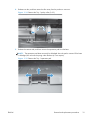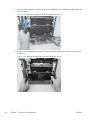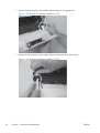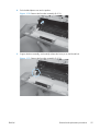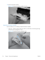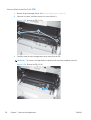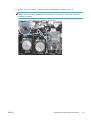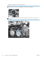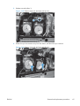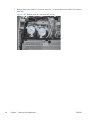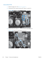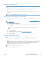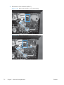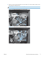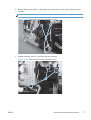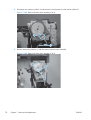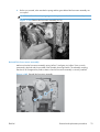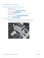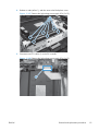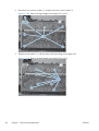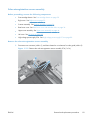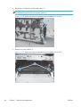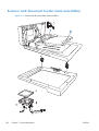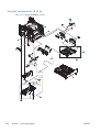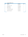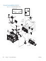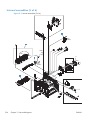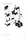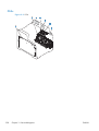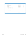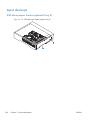
1
LASERJET PRO 300 COLOR MFP
LASERJET PRO 400 COLOR MFP
Service Manual
M375
M475
HP LaserJet Pro 300 color MFP M375
and HP LaserJet Pro 400 color MFP
M475 Printers
Service Manual
Copyright and License
Trademark Credits
© 2012 Copyright Hewlett-Packard
Development Company, L.P.
Microsoft®, Windows®, Windows® XP,
and Windows Vista® are U.S. registered
trademarks of Microsoft Corporation.
Reproduction, adaptation, or translation
without prior written permission is
prohibited, except as allowed under the
copyright laws.
The information contained herein is subject
to change without notice.
The only warranties for HP products and
services are set forth in the express warranty
statements accompanying such products and
services. Nothing herein should be
construed as constituting an additional
warranty. HP shall not be liable for technical
or editorial errors or omissions contained
herein.
Part number: CE863-90966
Edition 3, 11/2012
ENERGY STAR and the ENERGY STAR mark
are registered U.S. marks.
Conventions used in this guide
TIP:
Tips provide helpful hints or shortcuts.
NOTE: Notes provide important information to explain a concept or to complete a task.
CAUTION: Cautions indicate procedures that you should follow to avoid losing data or damaging
the product.
WARNING! Warnings alert you to specific procedures that you should follow to avoid personal
injury, catastrophic loss of data, or extensive damage to the product.
ENWW
iii
iv
Conventions used in this guide
ENWW
Table of contents
1 Removal and replacement ................................................................................................ 1
Removal and replacement strategy ............................................................................................. 2
Introduction .............................................................................................................. 2
Removal and replacement strategy .............................................................................. 2
Electrostatic discharge ............................................................................................... 3
Required tools ........................................................................................................... 3
Types of screws ........................................................................................................ 4
Service approach ..................................................................................................................... 5
Before performing service .......................................................................................... 5
After performing service ............................................................................................. 5
Post-service tests ........................................................................................................ 6
Test 1 (print-quality test) ............................................................................... 6
Test 2 (copy-quality test) .............................................................................. 6
Test 3 (fax-quality test; fax models only) ........................................................ 6
Parts removal order ................................................................................................... 7
Removal and replacement procedures ........................................................................................ 9
Rollers and pads ....................................................................................................... 9
Transfer roller ............................................................................................ 9
Pickup roller (Tray 2 and Tray 3) ................................................................ 10
Separation roller (Trays 2 or 3) .................................................................. 13
Reinstall the separation roller ...................................................... 15
Document feeder pickup roller assembly ..................................................... 16
Pickup roller and separation pad (Tray 1) ................................................... 17
Main assemblies ..................................................................................................... 20
Print-cartridge drawer ............................................................................... 20
DIMM cover ............................................................................................ 22
Right cover .............................................................................................. 23
Document feeder input tray ........................................................................ 25
Scanner assembly .................................................................................... 26
Right-front cover and power button ............................................................. 28
Rear-upper cover ...................................................................................... 30
Paper-feed guide assembly ........................................................................ 31
ENWW
v
Rear door ................................................................................................ 32
Rear-lower cover and rear-door links .......................................................... 34
Remove the rear-lower cover and rear-door links ........................... 34
Rear-door rib assembly ............................................................................. 38
Remove the rear-door rib assembly .............................................. 38
Link guide ............................................................................................... 40
Control panel and right-arm mount ............................................................. 41
Reinstall the control panel and right-arm mount ............................. 42
Upper-cover assembly ............................................................................... 44
Remove the upper-cover assembly ............................................... 44
Reinstall the upper-cover assembly ............................................... 46
Left cover ................................................................................................ 48
Remove the left cover ................................................................. 48
Reinstall the left cover ................................................................ 50
Front-door assembly ................................................................................. 51
Remove the front-door assembly .................................................. 51
Reinstall the front-door assembly .................................................. 56
Intermediate transfer belt (ITB) .................................................................... 58
Reinstall the ITB ......................................................................... 61
Drum motor (M1) and developer motor (M2) ............................................... 62
Reinstall the drum motor (M1) and developer motor (M2) ............... 67
Intermediate PCA ..................................................................................... 68
Formatter PCA and fax PCA ...................................................................... 69
Remove the formatter PCA and fax PCA ....................................... 69
Wireless PCA .......................................................................................... 72
DC controller PCA .................................................................................... 73
Remove the DC controller PCA .................................................... 74
Fuser-motor assembly ................................................................................ 76
Remove the fuser-motor assembly ................................................ 76
Reinstall the fuser-motor assembly ................................................ 79
High-voltage power-supply PCA ................................................................. 80
Remove the high-voltage power-supply PCA .................................. 80
Color-misregistration sensor assembly ......................................................... 83
Remove the color-misregistration sensor assembly .......................... 83
Reinstall the color-misregistration sensor assembly ......................... 85
Fan (FM1) ............................................................................................... 87
USB PCA (fax/memory-card models) .......................................................... 89
Remove the USB PCA ................................................................ 89
Duplex-reverse drive assembly ................................................................... 90
Remove the duplex-reverse drive assembly .................................... 90
Fuser ...................................................................................................... 93
vi
ENWW
Remove the fuser ....................................................................... 93
Reinstall the fuser ...................................................................... 98
Paper-delivery assembly ............................................................................ 99
Remove the paper-delivery assembly ............................................ 99
Tray cassettes and optional Tray 3 assembly ............................................................ 102
2 Solve problems ............................................................................................................. 103
Solve problems checklist ....................................................................................................... 104
Menu map .......................................................................................................................... 105
Troubleshooting process ........................................................................................................ 106
Pretroubleshooting checklist .................................................................................... 106
Power-on checks ................................................................................................... 107
Troubleshooting tools ............................................................................................................ 108
Component diagnostics .......................................................................................... 108
LED diagnostics ...................................................................................... 108
Network LEDs (network models only) ......................................... 108
Control panel LEDs .................................................................. 108
Memory card LED (memory-card models only) ............................. 108
Component tests ................................................................................................... 109
Control-panel tests .................................................................................. 109
Diagrams ............................................................................................................. 110
Plug/jack locations ................................................................................. 110
Location of connectors ............................................................................ 111
DC controller PCA ................................................................... 111
Location of major components ................................................................. 113
Major components .................................................................. 113
Motors and fans ...................................................................... 115
Rollers .................................................................................... 116
PCAs ..................................................................................... 117
Optional 250-sheet cassette ..................................................... 118
General timing diagram .......................................................................... 119
General circuit diagram .......................................................................... 120
CPU/ASIC diagrams .............................................................................. 121
HVT/Toner EMP diagram ........................................................................ 123
Driver PCA diagram ............................................................................... 124
Duplexer PCA diagram ........................................................................... 125
FSR diagram .......................................................................................... 126
Internal print quality test pages ............................................................................... 127
Print quality troubleshooting page ............................................................ 127
Print quality assessment page .................................................................. 127
Print the Configuration Page .................................................................... 127
ENWW
vii
Service page ......................................................................................... 127
Clean the paper path ............................................................................. 128
Print-quality troubleshooting tools ............................................................................ 128
Repetitive image defects .......................................................................... 128
Calibrate the product .............................................................................. 129
Control panel menus .............................................................................................. 129
Setup Menu ........................................................................................... 129
HP Web Services menu ............................................................ 130
Reports menu .......................................................................... 131
Quick Forms menu .................................................................. 132
Fax Setup menu ...................................................................... 133
System Setup menu .................................................................. 136
Service menu .......................................................................... 141
Network Setup menu ............................................................... 143
Function specific menus ........................................................................... 144
Copy menu ............................................................................ 144
Fax menu ............................................................................... 146
Scan menu ............................................................................. 148
USB Flash Drive ...................................................................... 149
Interpret control panel messages ............................................................................. 149
Control panel message types ................................................................... 149
Control panel messages .......................................................................... 149
10.100X Supply Memory Error ................................................. 149
49 Error, Turn off then on ......................................................... 150
50.x Fuser Error ...................................................................... 150
52 Scanner Error .................................................................... 150
57 Fan Error, Turn off then on ................................................... 151
79 Error Turn off then on .......................................................... 151
Black Cartridge Low ................................................................ 151
Black in wrong position ............................................................ 151
Black Very Low ....................................................................... 152
Canceled scan. Clear document ................................................ 152
Canceled send. Clear document ............................................... 152
Communication error. .............................................................. 152
Cyan Cartridge Low ................................................................ 153
Cyan in wrong position ............................................................ 153
Cyan Very Low ....................................................................... 153
Device error, press OK ............................................................ 153
Device is busy. Try again later .................................................. 154
Document feeder door is open. ................................................. 154
Document feeder jam. Clear and reload. ................................... 154
viii
ENWW
Document feeder mispick. Reload .............................................. 154
Door open .............................................................................. 155
Engine Communication Error .................................................... 155
Engine error. Press OK to continue. ........................................... 155
Fax is busy. Canceled send. ..................................................... 155
Fax is busy. Redial pending. ..................................................... 156
Fax receive error. .................................................................... 156
Fax Send error. ....................................................................... 157
Fax storage is full. Canceling the fax receive. ............................. 157
Fax storage is full. Canceling the fax send. ................................. 157
Fit to Page on flatbed only ........................................................ 158
Genuine HP supply installed ..................................................... 158
Incompatible <color> ............................................................... 158
Install [color] cartridge ............................................................. 158
Invalid driver Press OK ............................................................ 158
Invalid entry ........................................................................... 159
Jam in (area), Open door and clear jam .................................... 159
Jam in Tray 1, Clear jam and then press OK .............................. 159
Load paper ............................................................................ 159
Load Tray 1 <TYPE> <SIZE>, Press OK to use available media ..... 159
Load Tray 1, <PLAIN> <SIZE> / Cleaning mode, OK to start ....... 160
Load tray <X> Press [OK] for available media ............................ 160
Magenta Cartridge Low ........................................................... 160
Magenta in wrong position ...................................................... 160
Magenta Very Low .................................................................. 160
Manual Duplex Load Tray 1, Press OK ...................................... 161
Manual feed <SIZE> <TYPE>, Press OK to use available media .... 161
Memory is low. Press OK. ........................................................ 161
Memory is low. Try again later ................................................. 161
Memory low Only 1 copy made. Press OK to continue. ............... 161
Misprint, Press OK ................................................................... 162
No dial tone. .......................................................................... 162
No fax answer. Canceled send. ................................................ 162
No fax answer. Redial pending. ............................................... 163
No fax detected. ..................................................................... 163
Print failure, press OK. If error repeats, turn off then on. ............... 163
Remove shipping lock from <color> cartridge ............................. 164
Remove shipping locks from cartridges ...................................... 164
Replace [color] ....................................................................... 164
Scanner error #, Turn off then on .............................................. 164
Scanner reserved for PC scan ................................................... 165
ENWW
ix
Scanning error Cannot connect ................................................. 165
Settings cleared ...................................................................... 165
Unexpected size in tray # Load <size> Press [OK] ...................... 165
Unsupported <color> Press [OK] to continue ............................... 165
Used <color> in use ................................................................ 166
Used [color] installed, to accept press OK .................................. 166
Used supplies in use ................................................................ 166
Yellow Cartridge Low .............................................................. 166
Yellow in wrong position .......................................................... 166
Yellow Very Low ..................................................................... 167
Event-log messages ............................................................................................... 167
Print the event log ................................................................................... 167
Event log messages ................................................................................ 168
Clear jams .......................................................................................................................... 172
Common causes of jams ........................................................................................ 172
Jam locations ........................................................................................................ 172
Clear jams from the document feeder ...................................................................... 173
Clear jams in Tray 1 .............................................................................................. 175
Clear jams in Tray 2 .............................................................................................. 178
Clear jams in the fuser area ................................................................................... 179
Clear jams in the output bin .................................................................................... 180
Clear jams in the duplexer ..................................................................................... 181
Solve paper-handling problems .............................................................................................. 183
The product picks up multiple sheets of paper ........................................................... 183
The product does not pick up paper ........................................................................ 183
Solve image-quality problems ................................................................................................ 184
Print quality examples ............................................................................................ 184
Color image defects .............................................................................................. 188
Clean the product ................................................................................................................ 190
Clean the pickup and separation rollers ................................................................... 190
Clean the paper path ............................................................................................ 190
Clean the paper path from the product control panel .................................. 190
Clean the scanner glass strip and platen .................................................................. 191
Clean the document feeder pickup rollers and separation pad .................................... 192
Clean the touch screen .......................................................................................... 193
Solve performance problems ................................................................................................. 194
Factors affecting print performance ......................................................................... 194
Print speeds ........................................................................................... 195
The product does not print or it prints slowly ............................................................. 196
The product does not print ....................................................................... 196
The product prints slowly ......................................................................... 197
x
ENWW
Solve product connectivity problems ....................................................................................... 198
Solve direct-connect problems ................................................................................. 198
Solve network problems ......................................................................................... 198
Poor physical connection ......................................................................... 198
The computer is using the incorrect IP address for the product ...................... 198
The computer is unable to communicate with the product ............................ 199
The product is using incorrect link and duplex settings for the network .......... 199
New software programs might be causing compatibility problems ................ 199
The computer or workstation might be set up incorrectly .............................. 199
The product is disabled, or other network settings are incorrect .................... 199
Solve wireless network problems ............................................................................. 199
Wireless connectivity checklist ................................................................. 200
The control panel displays the message: The wireless feature on this product
has been turned off ................................................................................ 200
The product does not print after the wireless configuration completes ............ 200
The product does not print, and the computer has a third-party firewall
installed ................................................................................................ 201
The wireless connection does not work after moving the wireless router or
product ................................................................................................. 201
Cannot connect more computers to the wireless product .............................. 201
The wireless product loses communication when connected to a VPN ........... 202
The network does not appear in the wireless networks list ........................... 202
The wireless network is not functioning ...................................................... 202
Service mode functions ......................................................................................................... 203
Service menu ........................................................................................................ 203
Service menu settings .............................................................................. 203
Secondary service menu ........................................................................................ 203
Open the secondary service menu ............................................................ 204
Secondary service menu structure ............................................................. 204
Product resets ....................................................................................................... 205
Restore the factory-set defaults ................................................................. 205
NVRAM initialization .............................................................................. 205
Solve fax problems ............................................................................................................... 207
Fax troubleshooting checklist .................................................................................. 207
Fax error messages ............................................................................................... 209
Communication error. ............................................................................. 209
Document feeder door is open. Canceled fax. ........................................... 209
Fax is busy. Canceled send. .................................................................... 209
Fax is busy. Redial pending. .................................................................... 210
Fax receive error. ................................................................................... 210
Fax Send error. ...................................................................................... 211
ENWW
xi
Fax storage is full. Canceling the fax receive. ............................................ 211
Fax storage is full. Canceling the fax receive. ............................................ 211
Fax storage is full. Canceling the fax send. ................................................ 212
No dial tone. ......................................................................................... 212
No fax answer. Canceled send. ............................................................... 212
No fax answer. Redial pending. .............................................................. 213
No fax detected. .................................................................................... 213
Troubleshoot fax codes and trace reports ................................................................. 215
View and interpret fax error codes ........................................................... 215
Fax trace report ..................................................................................... 216
Fax logs and reports .............................................................................................. 216
Print all fax reports ................................................................................. 217
Print individual fax reports ....................................................................... 217
Set the fax error report ............................................................................ 218
Change error correction and fax speed ................................................................... 218
Set the fax-error-correction mode .............................................................. 218
Change the fax speed ............................................................................ 219
Solve problems sending faxes ................................................................................. 219
An error message displays on the control panel ......................................... 219
The Communication error. message displays .............................. 219
No dial tone. .......................................................................... 220
The Fax is busy. message displays ............................................ 221
The No fax answer. message displays ....................................... 221
Document feeder paper jam ..................................................... 222
The Fax storage is full. message displays ................................... 222
Scanner error ......................................................................... 222
The control panel displays a Ready message with no attempt to send the fax . 222
The control panel displays the message "Storing page 1" and does not
progress beyond that message ................................................................. 223
Faxes can be received, but not sent .......................................................... 223
Unable to use fax functions from the control panel ...................................... 223
Unable to use speed dials ....................................................................... 224
Unable to use group dials ....................................................................... 224
Receive a recorded error message from the phone company when trying to
send a fax ............................................................................................. 224
Unable to send a fax when a phone is connected to the product .................. 225
Solve problems receiving faxes ............................................................................... 226
The fax does not respond ........................................................................ 226
The fax has a dedicated phone line ........................................... 226
An answering machine is connected to the product ..................... 226
A telephone handset is connected to the product ......................... 227
xii
ENWW
The Answer Mode setting is set to the Manual setting ................... 227
Voice mail is available on the fax line ........................................ 227
The product is connected to a DSL phone service ........................ 228
The product uses a fax over IP or VoIP phone service ................... 228
An error message displays on the control panel ......................................... 229
The No fax detected. message displays ..................................... 229
The Communication error. message displays .............................. 229
The Fax storage is full. message displays ................................... 230
The Fax is busy. message displays ............................................ 230
A fax is received but does not print .......................................................... 231
The Private Receive feature is on ............................................... 231
Sender receives a busy signal .................................................................. 231
A handset is connected to the product ........................................ 231
A phone line splitter is being used ............................................. 231
No dial tone .......................................................................................... 231
Cannot send or receive a fax on a PBX line ............................................... 231
Solve general fax problems .................................................................................... 232
Faxes are sending slowly ........................................................................ 232
Fax quality is poor ................................................................................. 233
Fax cuts off or prints on two pages ........................................................... 233
Product updates ................................................................................................................... 235
3 Parts and diagrams ...................................................................................................... 237
Order parts by authorized service providers ............................................................................ 238
Orderable parts .................................................................................................... 238
Whole unit replacement ......................................................................................... 238
Related documentation and software ....................................................................... 239
Supplies and accessories ....................................................................................... 239
Service parts ........................................................................................................ 239
How to use the parts lists and diagrams .................................................................................. 240
Scanner and document feeder main assemblies ....................................................................... 242
Covers ................................................................................................................................ 244
Internal assemblies ............................................................................................................... 246
Internal assemblies (1 of 6) ..................................................................................... 246
Internal assemblies (2 of 6) ..................................................................................... 248
Internal components (3 of 6) ................................................................................... 250
Internal assemblies (4 of 6) ..................................................................................... 252
Internal assemblies (5 of 6) ..................................................................................... 254
Internal assemblies (6 of 6) ..................................................................................... 256
PCAs ................................................................................................................... 258
Input device(s) ..................................................................................................................... 260
ENWW
xiii
250-sheet paper feeder (optional Tray 3) ................................................................. 260
Alphabetical parts list ........................................................................................................... 262
Numerical parts list .............................................................................................................. 265
Appendix A Service and support ..................................................................................... 269
Hewlett-Packard limited warranty statement ............................................................................. 270
HP's Premium Protection Warranty: LaserJet print cartridge limited warranty statement .................. 272
Data stored on the print cartridge ........................................................................................... 273
End User License Agreement .................................................................................................. 274
OpenSSL ............................................................................................................................. 277
Customer support ................................................................................................................. 278
Appendix B Product specifications ................................................................................... 279
Physical specifications .......................................................................................................... 280
Power consumption, electrical specifications, and acoustic emissions .......................................... 280
Environmental specifications .................................................................................................. 280
Appendix C Regulatory information ................................................................................. 281
FCC regulations ................................................................................................................... 282
Environmental product stewardship program ........................................................................... 282
Protecting the environment ...................................................................................... 282
Ozone production ................................................................................................. 282
Power consumption ............................................................................................... 282
Toner consumption ................................................................................................ 283
Paper use ............................................................................................................. 283
Plastics ................................................................................................................. 283
HP LaserJet print supplies ....................................................................................... 283
Return and recycling instructions ............................................................................. 283
United States and Puerto Rico .................................................................. 283
Multiple returns (more than one cartridge) .................................. 284
Single returns .......................................................................... 284
Shipping ................................................................................ 284
Non-U.S. returns .................................................................................... 284
Paper .................................................................................................................. 285
Material restrictions ............................................................................................... 285
Disposal of waste equipment by users in private households in the European Union ...... 285
Chemical substances ............................................................................................. 286
Material Safety Data Sheet (MSDS) ......................................................................... 286
For more information ............................................................................................. 287
Declaration of conformity ...................................................................................................... 288
xiv
ENWW
Declaration of conformity (wireless models) ............................................................................. 290
Certificate of volatility ........................................................................................................... 292
Types of memory ................................................................................................... 292
Volatile memory ..................................................................................... 292
Non-volatile memory .............................................................................. 292
Safety statements ................................................................................................................. 293
Laser safety .......................................................................................................... 293
Canadian DOC regulations .................................................................................... 293
VCCI statement (Japan) .......................................................................................... 293
Power cord instructions .......................................................................................... 293
Power cord statement (Japan) ................................................................................. 293
EMC statement (Korea) .......................................................................................... 294
Laser statement for Finland ..................................................................................... 294
GS statement (Germany) ........................................................................................ 295
Substances Table (China) ....................................................................................... 295
Restriction on Hazardous Substances statement (Turkey) ............................................. 295
Restriction on Hazardous Substances statement (Ukraine) ........................................... 295
Additional statements for telecom (fax) products ....................................................................... 296
EU Statement for Telecom Operation ....................................................................... 296
New Zealand Telecom Statements ........................................................................... 296
Additional FCC statement for telecom products (US) .................................................. 296
Telephone Consumer Protection Act (US) .................................................................. 297
Industry Canada CS-03 requirements ...................................................................... 297
Vietnam Telecom wired/wireless marking for ICTQC Type approved products ............. 298
Additional statements for wireless products .............................................................................. 299
FCC compliance statement—United States ................................................................ 299
Australia statement ................................................................................................ 299
Brazil ANATEL statement ........................................................................................ 299
Canadian statements ............................................................................................. 299
European Union regulatory notice ........................................................................... 299
Notice for use in France ......................................................................................... 300
Notice for use in Russia ......................................................................................... 300
Korean statement .................................................................................................. 300
Taiwan statement .................................................................................................. 301
Vietnam Telecom wired/wireless marking for ICTQC Type approved products ............. 301
Index ............................................................................................................................... 303
ENWW
xv
xvi
ENWW
List of tables
Table 1-1 Common fasteners ................................................................................................................. 4
Table 2-1 Major components ............................................................................................................. 113
Table 2-2 Solenoid, sensors, and motors .............................................................................................. 115
Table 2-3 Rollers ............................................................................................................................... 116
Table 2-4 PCAs ................................................................................................................................ 117
Table 2-5 Optional 250-sheet cassette ................................................................................................. 118
Table 2-6 Repetitive image defects ...................................................................................................... 128
Table 2-7 Event-log messages ............................................................................................................. 168
Table 2-8 Event-log-only messages ...................................................................................................... 170
Table 2-9 Secondary service menu ...................................................................................................... 204
Table 3-1 Order parts, accessories, and supplies .................................................................................. 238
Table 3-2 Pro 300 Color MFP M375nw .............................................................................................. 238
Table 3-3 Pro 400 Color MFP M475dn ............................................................................................... 238
Table 3-4 Pro 400 Color M475dw ..................................................................................................... 238
Table 3-5 Related documentation and software .................................................................................... 239
Table 3-6 Scanner and document feeder main assemblies ..................................................................... 243
Table 3-7 Covers .............................................................................................................................. 245
Table 3-8 Internal assemblies (1 of 6) .................................................................................................. 247
Table 3-9 Internal assemblies (2 of 6) .................................................................................................. 249
Table 3-10 Internal assemblies (3 of 6) ................................................................................................ 251
Table 3-11 Internal assemblies (4 of 6) ................................................................................................ 253
Table 3-12 Internal assemblies (5 of 6) ................................................................................................ 255
Table 3-13 Internal assemblies (6 of 6) ................................................................................................ 257
Table 3-14 PCAs .............................................................................................................................. 259
Table 3-15 250-sheet paper feeder (optional Tray 3) ............................................................................ 261
Table 3-16 Alphabetical parts list ....................................................................................................... 262
Table 3-17 Numerical parts list ........................................................................................................... 265
Table B-1 Physical specifications ......................................................................................................... 280
Table B-2 Environmental specifications1 ............................................................................................... 280
ENWW
xvii
xviii
ENWW
List of figures
Figure 1-1 Phillips and pozidrive screwdriver comparison .......................................................................... 3
Figure 1-2 Parts removal order (1 of 2) .................................................................................................... 7
Figure 1-3 Parts removal order (2 of 2) .................................................................................................... 8
Figure 1-4 Remove the pickup roller (1 of 2) ........................................................................................... 11
Figure 1-5 Remove the pickup roller (2 of 2) ........................................................................................... 12
Figure 1-6 Remove the pickup roller (1 of 3) ........................................................................................... 13
Figure 1-7 Remove the separation roller (2 of 3) ..................................................................................... 14
Figure 1-8 Remove the separation roller (3 of 3) ..................................................................................... 14
Figure 1-9 Reinstall the separation roller ................................................................................................ 15
Figure 1-10 Remove the document feeder pickup roller assembly (1 of 2) .................................................. 16
Figure 1-11 Remove the document feeder pickup roller assembly (2 of 2) .................................................. 16
Figure 1-12 Remove the Tray 1 pickup roller (1 of 3) .............................................................................. 18
Figure 1-13 Remove the Tray 1 pickup roller (2 of 3) .............................................................................. 18
Figure 1-14 Remove the Tray 1 pickup roller (3 of 3) .............................................................................. 19
Figure 1-15 Remove the Tray 1 separation pad ...................................................................................... 19
Figure 1-16 Remove the print-cartridge drawer (1 of 3) ........................................................................... 20
Figure 1-17 Remove the print-cartridge drawer (2 of 3) ........................................................................... 20
Figure 1-18 Remove the print-cartridge drawer (3 of 3) ........................................................................... 21
Figure 1-19 Remove the DIMM cover .................................................................................................... 22
Figure 1-20 Remove the right cover (1 of 3) ........................................................................................... 23
Figure 1-21 Remove the right cover (2 of 3) ........................................................................................... 23
Figure 1-22 Remove the right cover (3 of 3) ........................................................................................... 24
Figure 1-23 Remove the document feeder input tray (1 of 2) .................................................................... 25
Figure 1-24 Remove the document feeder input tray (2 of 2) .................................................................... 25
Figure 1-25 Remove the scanner assembly (1 of 4) ................................................................................. 26
Figure 1-26 Remove the scanner assembly (2 of 4) ................................................................................. 26
Figure 1-27 Remove the scanner assembly (3 of 4) ................................................................................. 27
Figure 1-28 Remove the scanner assembly (4 of 4) ................................................................................. 27
Figure 1-29 Remove the rear-upper cover (1 of 2) ................................................................................... 30
Figure 1-30 Remove the rear-upper cover (2 of 2) ................................................................................... 30
Figure 1-31 Remove the feed assembly (1 of 2) ...................................................................................... 31
Figure 1-32 Remove the feed assembly (2 of 2) ...................................................................................... 31
ENWW
xix
Figure 1-33 Remove the rear door (1 of 4) ............................................................................................. 32
Figure 1-34 Remove the rear door (2 of 4) ............................................................................................. 32
Figure 1-35 Remove the rear door (3 of 4) ............................................................................................. 33
Figure 1-36 Remove the rear door (4 of 4) ............................................................................................. 33
Figure 1-37 Remove the rear- lower cover and rear-door links (1 of 6) ....................................................... 34
Figure 1-38 Remove the rear-lower cover and rear-door links (2 of 6) ........................................................ 35
Figure 1-39 Remove the rear-lower cover and rear-door links (3 of 6) ........................................................ 35
Figure 1-40 Remove the rear-lower cover and link-guides (4 of 6) ............................................................. 36
Figure 1-41 Remove the rear-lower cover and link-guides (5 of 6) ............................................................. 36
Figure 1-42 Remove the rear-lower cover and rear-door links (6 of 6) ........................................................ 37
Figure 1-43 Remove the rear-door rib assembly (1 of 3) .......................................................................... 38
Figure 1-44 Remove the rear-door rib assembly (2 of 3) .......................................................................... 39
Figure 1-45 Remove the rear-door rib assembly (3 of 3) .......................................................................... 39
Figure 1-46 Replace the link guide ........................................................................................................ 40
Figure 1-47 Remove the control panel and right-arm mount (1 of 3) .......................................................... 41
Figure 1-48 Remove the control panel and right-arm mount (2 of 3) .......................................................... 41
Figure 1-49 Remove the control panel and right-arm mount (3 of 3) .......................................................... 42
Figure 1-50 Reinstall the control panel and right-arm mount (1 of 2) .......................................................... 42
Figure 1-51 Reinstall the control panel and right-arm mount (2 of 2) .......................................................... 43
Figure 1-52 Remove the upper-cover assembly (1 of 3) ............................................................................ 44
Figure 1-53 Remove the upper-cover assembly (2 of 3) ............................................................................ 45
Figure 1-54 Remove the upper-cover assembly (3 of 3) ............................................................................ 45
Figure 1-55 Reinstall the upper-cover assembly (1 of 3) ........................................................................... 46
Figure 1-56 Reinstall the upper-cover assembly (2 of 3) ........................................................................... 46
Figure 1-57 Reinstall the upper-cover assembly (3 of 3) ........................................................................... 47
Figure 1-58 Remove the left cover (1 of 3) ............................................................................................. 48
Figure 1-59 Remove the left cover (2 of 3) ............................................................................................. 49
Figure 1-60 Remove the left cover (3 of 3) ............................................................................................. 49
Figure 1-61 Reinstall the left cover (1 of 2) ............................................................................................. 50
Figure 1-62 Reinstall the left cover (2 of 2) ............................................................................................. 50
Figure 1-63 Remove the front-door assembly (1 of 10) ............................................................................. 51
Figure 1-64 Remove the front-door assembly (2 of 10) ............................................................................. 52
Figure 1-65 Remove the front-door assembly (3 of 10) ............................................................................. 52
Figure 1-66 Remove the front-door assembly (4 of 10) ............................................................................. 53
Figure 1-67 Remove the front-door assembly (5 of 10) ............................................................................. 53
Figure 1-68 Remove the front-door assembly (6 of 10) ............................................................................. 54
Figure 1-69 Remove the front-door assembly (7 of 10) ............................................................................. 54
Figure 1-70 Remove the front-door assembly (8 of 10) ............................................................................. 55
Figure 1-71 Remove the front-door assembly (9 of 10) ............................................................................. 55
Figure 1-72 Remove the front-door assembly (10 of 10) ........................................................................... 56
Figure 1-73 Reinstall the front-door assembly (1 of 2) .............................................................................. 56
xx
ENWW
Figure 1-74 Reinstall the front-door assembly (2 of 2) .............................................................................. 57
Figure 1-75 Remove the ITB (1 of 6) ...................................................................................................... 58
Figure 1-76 Remove the ITB (2 of 6) ...................................................................................................... 58
Figure 1-77 Remove the ITB (3 of 6) ...................................................................................................... 59
Figure 1-78 Remove the ITB (4 of 6) ...................................................................................................... 59
Figure 1-79 Remove the ITB (5 of 6) ...................................................................................................... 60
Figure 1-80 Remove the ITB (6 of 6) ...................................................................................................... 60
Figure 1-81 Reinstall the ITB ................................................................................................................. 61
Figure 1-82 Remove motor M1 and motor M2 (1 of 6) ............................................................................ 62
Figure 1-83 Remove motor M1 and motor M2 (2 of 6) ............................................................................ 63
Figure 1-84 Remove motor M1 and motor M2 (3 of 6) ............................................................................ 64
Figure 1-85 Remove motor M1 and motor M2 (4 of 6) ............................................................................ 65
Figure 1-86 Remove motor M1 and motor M2 (5 of 6) ............................................................................ 65
Figure 1-87 Remove motor M1 and motor M2 (6 of 6) ............................................................................ 66
Figure 1-88 Reinstall the motor M1 and motor M2 wire-harness retainer .................................................... 67
Figure 1-89 Remove the Intermediate PCA (1 of 2) .................................................................................. 68
Figure 1-90 Remove the Intermediate PCA (2 of 2) .................................................................................. 68
Figure 1-91 Remove the formatter (1 of 4; base model) ........................................................................... 70
Figure 1-92 Remove the formatter (2 of 4; fax model) .............................................................................. 70
Figure 1-93 Remove the formatter (3 of 4; base model) ........................................................................... 71
Figure 1-94 Remove the formatter (4 of 4; fax model) .............................................................................. 71
Figure 1-95 Remove the wirelss PCA (1 of 2) ......................................................................................... 72
Figure 1-96 Remove the wirelss PCA (2 of 2) ......................................................................................... 72
Figure 1-97 Remove the DC controller PCA (1 of 2) ................................................................................ 74
Figure 1-98 Remove the DC controller PCA (2 of 2) ................................................................................ 75
Figure 1-99 Remove the fuser-motor assembly (1 of 6) ............................................................................. 76
Figure 1-100 Remove the fuser-motor assembly (2 of 6) ........................................................................... 77
Figure 1-101 Remove the fuser-motor assembly (3 of 6) ........................................................................... 77
Figure 1-102 Remove the fuser-motor assembly (4 of 6) ........................................................................... 78
Figure 1-103 Remove the fuser-motor assembly (5 of 6) ........................................................................... 78
Figure 1-104 Remove the fuser-motor assembly (6 of 6) ........................................................................... 79
Figure 1-105 Reinstall the fuser-motor assembly ...................................................................................... 79
Figure 1-106 Remove the high-voltage power-supply PCA (1 of 5) ............................................................ 80
Figure 1-107 Remove the high-voltage power-supply PCA (2 of 5) ............................................................ 81
Figure 1-108 Remove the high-voltage power-supply PCA (3 of 5) ............................................................ 81
Figure 1-109 Remove the high-voltage power-supply PCA (4 of 5) ............................................................ 82
Figure 1-110 Remove the high-voltage power-supply PCA (5 of 5) ............................................................ 82
Figure 1-111 Remove the color-misregistration sensor assembly PCA (1 of 4) ............................................. 83
Figure 1-112 Remove the color-misregistration sensor assembly PCA (2 of 4) ............................................. 84
Figure 1-113 Remove the color-misregistration sensor assembly PCA (3 of 4) ............................................. 84
Figure 1-114 Remove the color-misregistration sensor assembly PCA (4 of 4) ............................................. 85
ENWW
xxi
Figure 1-115 Reinstall the color-misregistration sensor assembly PCA (1 of 2) ............................................. 85
Figure 1-116 Reinstall the color-misregistration sensor assembly PCA (2 of 2) ............................................. 86
Figure 1-117 Remove the fan (FM1) (1 of 2) .......................................................................................... 87
Figure 1-118 Remove the fan (FM1) (2 of 2) .......................................................................................... 88
Figure 1-119 Remove the USB PCA (fax/memory-card models) ................................................................ 89
Figure 1-120 Remove the duplex-reverse drive assembly (1 of 4) .............................................................. 90
Figure 1-121 Remove the duplex-reverse drive assembly (2 of 4) .............................................................. 91
Figure 1-122 Remove the duplex-reverse drive assembly (3 of 4) .............................................................. 91
Figure 1-123 Remove the duplex-reverse drive assembly (4 of 4) .............................................................. 92
Figure 1-124 Remove the fuser (1 of 8) ................................................................................................. 93
Figure 1-125 Remove the fuser (2 of 8) ................................................................................................. 94
Figure 1-126 Remove the fuser (3 of 8) ................................................................................................. 94
Figure 1-127 Remove the fuser (4 of 8) ................................................................................................. 95
Figure 1-128 Remove the fuser (5 of 8) ................................................................................................. 95
Figure 1-129 Remove the fuser (6 of 8) ................................................................................................. 96
Figure 1-130 Remove the fuser (7 of 8) ................................................................................................. 96
Figure 1-131 Remove the fuser (8 of 8) ................................................................................................. 97
Figure 1-132 Reinstall the fuser ............................................................................................................. 98
Figure 1-133 Remove the paper-delivery assembly (1 of 4) ...................................................................... 99
Figure 1-134 Remove the paper-delivery assembly (2 of 4) .................................................................... 100
Figure 1-135 Remove the paper-delivery assembly (3 of 4) .................................................................... 100
Figure 1-136 Remove the paper-delivery assembly (4 of 4) .................................................................... 101
Figure 1-137 Remove the tray cassettes and optional Tray 3 assembly (1 of 2) ......................................... 102
Figure 1-138 Remove the tray cassettes and optional Tray 3 assembly (2 of 2) ......................................... 102
Figure 2-1 Control-panel test .............................................................................................................. 109
Figure 2-2 DC controller connectors .................................................................................................... 111
Figure 2-3 Major components ............................................................................................................ 113
Figure 2-4 Motors and fans ................................................................................................................ 115
Figure 2-5 Rollers .............................................................................................................................. 116
Figure 2-6 PCAs ............................................................................................................................... 117
Figure 2-7 Optional 250-sheet cassette ................................................................................................ 118
Figure 2-8 Timing diagram ................................................................................................................. 119
Figure 2-9 Circuit diagram ................................................................................................................. 120
Figure 2-10 CPU diagram ................................................................................................................. 121
Figure 2-11 ASIC diagram ................................................................................................................. 122
Figure 2-12 HVT/Toner EMP diagram ................................................................................................. 123
Figure 2-13 Driver PCA diagram ........................................................................................................ 124
Figure 2-14 Duplexer PCA diagram .................................................................................................... 125
Figure 2-15 FSR diagram ................................................................................................................... 126
Figure 2-16 Control-panel test ............................................................................................................ 167
Figure 2-17 Control-panel test ............................................................................................................ 203
xxii
ENWW
Figure 3-1 Scanner and document feeder main assemblies .................................................................... 242
Figure 3-2 External panels and covers ................................................................................................. 244
Figure 3-3 Internal assemblies (1 of 6) ................................................................................................. 246
Figure 3-4 Internal assemblies (2 of 6) ................................................................................................. 248
Figure 3-5 Internal assemblies (3 of 6) ................................................................................................. 250
Figure 3-6 Internal assemblies (4 of 6) ................................................................................................. 252
Figure 3-7 Internal assemblies (5 of 6) ................................................................................................. 254
Figure 3-8 Internal assemblies (6 of 6) ................................................................................................. 256
Figure 3-9 PCAs ............................................................................................................................... 258
Figure 3-10 250-sheet paper feeder (optional Tray 3) ........................................................................... 260
ENWW
xxiii
xxiv
ENWW
1
ENWW
Removal and replacement
●
Removal and replacement strategy
●
Service approach
●
Removal and replacement procedures
1
Removal and replacement strategy
This chapter discusses the removal and replacement of field replaceable units (FRUs) only.
Replacing FRUs is generally the reverse of removal. Occasionally, notes and tips are included to
provide directions for difficult or critical replacement procedures.
HP does not support repairing individual subassemblies or problem solving at the component level.
Note the length, diameter, color, type, and location of each screw. Be sure to return each screw to its
original location during reassembly.
Incorrectly routed or loose wire harnesses can interfere with other internal components and can become
damaged or broken. Frayed or pinched harness wires can be difficult to locate. When replacing wire
harnesses, always use the provided wire loops, lance points, or wire-harness guides.
Introduction
This chapter describes the removal and replacement of field-replaceable units (FRUs) only.
Replacing FRUs is generally the reverse of removal. Occasionally, notes and tips are included to
provide directions for difficult or critical replacement procedures.
HP does not support repairing individual subassemblies or troubleshooting to the component level.
Note the length, diameter, color, type, and location of each screw. Be sure to return each screw to its
original location during reassembly.
Incorrectly routed or loose wire harnesses can interfere with other internal components and can become
damaged or broken. Frayed or pinched harness wires can be difficult to find. When replacing wire
harnesses, always use the provided wire loops, lance points, or wire-harness guides and retainers.
Removal and replacement strategy
WARNING! Turn the product off, wait 5 seconds, and then remove the power cord before
attempting to service the product. If this warning is not followed, severe injury can result, in addition to
damage to the product. The power must be on for certain functional checks during troubleshooting.
However, disconnect the power supply during parts removal.
Never operate or service the product with the protective cover removed from the laser/scanner
assembly. The reflected beam, although invisible, can damage your eyes.
The sheet-metal parts can have sharp edges. Be careful when handling sheet-metal parts.
CAUTION: Do not bend or fold the flat flexible cables (FFCs) during removal or installation. Also, do
not straighten pre-folds in the FFCs. You must fully seat all FFCs in their connectors. Failure to fully seat
an FFC into a connector can cause a short circuit in a PCA.
NOTE: To install a self-tapping screw, first turn it counterclockwise to align it with the existing thread
pattern, and then carefully turn it clockwise to tighten. Do not overtighten. If a self-tapping screw-hole
becomes stripped, repair the screw-hole or replace the affected assembly.
2
Chapter 1 Removal and replacement
ENWW
TIP: For clarity, some photos in this chapter show components removed that would not be removed to
service the product. If necessary, remove the components listed at the beginning of a procedure before
proceeding to service the product.
Electrostatic discharge
CAUTION:
Some parts are sensitive to electrostatic discharge (ESD). Look for the ESD reminder
when removing product parts. Always perform service work at an ESD-protected workstation or mat, or
use an ESD strap. If an ESD workstation, mat, or strap is not available, ground yourself by touching the
sheet-metal chassis before touching an ESD-sensitive part.
Protect the ESD-sensitive parts by placing them in ESD pouches when they are out of the product.
Required tools
●
Number 2 Phillips screwdriver with a magnetic tip and a 152-mm (6-inch) shaft length
●
Precision slotted screwdriver with a 1 mm (0.04 in) blade width
NOTE: This fine-point tool is required to release the front door pins. The width of the blade must
be 2 mm (0.08 in) or less to be able to drive the door pins out of the mounting holes.
●
Small, slotted screwdriver
●
Needle-nose pliers
●
Snap-ring pliers
●
ESD mat (if one is available)
●
Penlight (optional)
CAUTION: Always use a Phillips screwdriver (callout 1). Do not use a pozidrive screwdriver
(callout 2) or any motorized screwdriver. These can damage screws or screw threads.
Figure 1-1 Phillips and pozidrive screwdriver comparison
ENWW
Removal and replacement strategy
3
Types of screws
WARNING! Make sure that components are replaced with the correct screw type. Using the
incorrect screw (for example, substituting a long screw for the correct shorter screw) can cause damage
to the product or interfere with product operation. Do not intermix screws that are removed from one
component by using the screws that are removed from another component.
NOTE: The screw illustrations in the following table are for reference only. Screws might vary in size
and appearance from those shown in this table.
Table 1-1 Common fasteners
Example
Description
Size
Part Number
Screw, with washer
M3X8
XA9-1420-000CN
M4X6
XB2-7400-605CN
M4X12
XA9-1422-000CN
M4X10
XB4-7401-005CN
M4X15
XB4-7401-609CN
M3X4
XB6-7300-405CN
M3X6
XB6-7300-605CN
M3X6
XA9-1670-000CN
M3X8
XA9-1671-000CN
Screw, machine
M3X4
XB6-7300-409CN
Screw, machine, flat head
M3X4
XA9-0679-000CN
Screw, machine, flanged pan
head
M3X6
XB6-7300-805CN
Screw, tapping, truss head
Screw, TP
Screw, D
12 mm
4
Chapter 1 Removal and replacement
ENWW
Service approach
Before performing service
●
Remove all media from the product.
●
Turn off the power using the power switch.
●
Unplug the power cable and interface cable(s).
●
Place the product on an ESD mat (if one is available). If an ESD workstation or mat is not
available, ground yourself by touching the sheet-metal chassis before touching an ESD-sensitive
part.
●
Remove the toner cartridges.
●
Remove the tray 2 cassette.
After performing service
ENWW
●
Connect the power cable.
●
Reinstall the toner cartridges.
●
Reinstall the tray 2 cassette.
Service approach
5
Post-service tests
After service has been completed, perform the following tests to verify that the repair or replacement
was successful.
Test 1 (print-quality test)
1.
Verify that you have completed the necessary reassembly steps.
2.
Make sure that the input tray contains clean, unmarked paper.
3.
Attach the power cable and interface cable, and then turn on the product.
4.
Verify that the expected start-up sounds occur.
5.
Print a configuration page, and then verify that the expected printing sounds occur.
6.
Print a demo page, and then verify that the print quality is as expected.
7.
Send a print job from the host computer, and then verify that the output meets expectations.
8.
If necessary, restore any customer-specified settings.
9.
Clean the outside of the product by using a damp cloth.
Test 2 (copy-quality test)
1.
Verify that you have completed the necessary reassembly steps.
2.
Make sure that the input tray contains clean, unmarked paper.
3.
Attach the power cable, and then turn on the product.
4.
Verify that the expected start-up sounds occur.
5.
Print a configuration page, and then verify that the expected printing sounds occur.
6.
Place the configuration page in the document feeder.
7.
Print a copy job, and then verify the results.
8.
Clean the outside of the product by using a damp cloth.
Test 3 (fax-quality test; fax models only)
6
1.
Place the configuration page in the document feeder.
2.
Type a valid fax number and send the fax job.
3.
Verify that the send quality and receive quality meet expectations.
Chapter 1 Removal and replacement
ENWW
Parts removal order
Figure 1-2 Parts removal order (1 of 2)
ENWW
Service approach
7
Figure 1-3 Parts removal order (2 of 2)
8
Chapter 1 Removal and replacement
ENWW
Removal and replacement procedures
Rollers and pads
Transfer roller
The transfer roller is a component of the paper-feed assembly and not available as an individual FRU.
To remove and replace the transfer roller, install a replacement paper-feed guide assembly. See Paperfeed guide assembly on page 31.
ENWW
Removal and replacement procedures
9
Pickup roller (Tray 2 and Tray 3)
The roller must be rotated into the service position to remove it.
CAUTION: Avoid touching the spongy roller surface unless you are going to replace the roller. Skin
oils on the roller can cause paper pickup problems.
1.
Turn the product on, and wait for it to reach the Ready state. Perform the following steps to rotate
the roller to the service position.
NOTE: If you have removed Tray 2 to service the product, reinstall the tray before turning the
power on.
TIP: The following steps rotate the engine pickup roller and the Tray 1 pickup roller into the
service position.
a.
Simultaneously press the Left Arrow
Service menu.
b.
Touch the Pick Roller item.
button and the Cancel
button to open the 2ndry
Touch the OK button to confirm that you want the roller to rotate.
c.
Listen for the roller to rotate. When the roller is done rotating, unplug the power cable and
then place the power button in the off position.
CAUTION: It is important to place the power button in the off position after unplugging
the power cable so that the product power does not come on immediately when the power
cable is plugged in again.
10
d.
Remove Tray 2.
e.
Perform the remaining steps in this procedure to remove the roller. After replacing the roller,
plug the power cable into the product, and then use the power button to turn the power on.
Chapter 1 Removal and replacement
ENWW
2.
Carefully raise the front of the product.
WARNING! Do not place the product face-up resting on the rear cover and rear door. Excess
toner might enter the laser/scanner assembly and contaminate the mirrors, causing print-quality
problems. The laser/scanner is not a FRU. If the laser/scanner mirrors are contaminated, the entire
product must be replaced.
CAUTION: The document feeder and scanner cover are not captive and can open suddenly
when the product is placed front-side face up. Always support the document feeder and scanner
cover before placing the product front-side face up.
Do not lift the product grasping the front door and Tray 2 cavity.
NOTE: The roller is located inside the tray cavity.
Figure 1-4 Remove the pickup roller (1 of 2)
ENWW
Removal and replacement procedures
11
3.
Use a pair of snap-ring pliers to release two locking tabs and remove the pickup roller.
CAUTION: Do not touch the spongy roller surface unless you are going to replace the roller.
Skin oils on the roller can cause paper pickup problems.
NOTE: If you do not have a pair of snap-ring pliers, use your fingers to release the tabs.
Figure 1-5 Remove the pickup roller (2 of 2)
12
Chapter 1 Removal and replacement
ENWW
Separation roller (Trays 2 or 3)
CAUTION: Avoid touching the spongy roller surface unless you are going to replace the roller. Skin
oils on the roller can cause paper pickup problems.
1.
Remove Tray 2 (if installed), and then carefully raise the front of the product.
WARNING! Do not place the product face-up resting on the rear cover and rear door. Excess
toner might enter the laser/scanner assembly and contaminate the mirrors, causing print-quality
problems. The laser/scanner is not a FRU. If the laser/scanner mirrors are contaminated, the entire
product must be replaced.
CAUTION:
Do not lift the product grasping the front door and Tray 2 cavity.
NOTE: The roller is located inside the tray cavity.
Figure 1-6 Remove the pickup roller (1 of 3)
ENWW
Removal and replacement procedures
13
2.
Release the two roller-cover locking pins, and then remove the cover.
Figure 1-7 Remove the separation roller (2 of 3)
3.
Release the roller holder to release the roller-locking pins. Remove the separation roller.
Figure 1-8 Remove the separation roller (3 of 3)
14
Chapter 1 Removal and replacement
ENWW
Reinstall the separation roller
1.
Install the replacement separation roller.
2.
Reinstall the separation roller cover on the locking pins, and then rotate it toward the roller until
you hear it snap into place.
Figure 1-9 Reinstall the separation roller
ENWW
Removal and replacement procedures
15
Document feeder pickup roller assembly
IMPORTANT: The document feeder pickup roller must be shipped in the down position.
1.
Open the document feeder cover.
2.
Disconnect one spring (callout 1).
Figure 1-10 Remove the document feeder pickup roller assembly (1 of 2)
1
3.
Lift up on the end of the assembly, and then slide it toward the control panel to remove it.
Figure 1-11 Remove the document feeder pickup roller assembly (2 of 2)
2
1
16
Chapter 1 Removal and replacement
ENWW
Pickup roller and separation pad (Tray 1)
The roller must be rotated into the service position to remove it.
CAUTION: Avoid touching the spongy roller surface unless you are going to replace the roller. Skin
oils on the roller can cause paper pickup problems.
NOTE: Always replace the separation pad when replacing the pickup roller.
1.
Turn the product on, and wait for it to reach the Ready state. Perform the following steps to rotate
the roller to the service position.
NOTE: If you have removed Tray 2 to service the product, reinstall the tray before turning the
power on.
TIP: The following steps rotate the engine pickup roller and the Tray 1 pickup roller into the
service position.
a.
Open the 2ndry Service menu by pressing the Left Arrow
button simultaneously.
b.
Use the arrow buttons to select Pick Roller, and then press the OK button.
button and the Cancel
Touch the OK button again to confirm that you want the roller to rotate.
c.
Listen for the roller to rotate. When the roller is done rotating, unplug the power cable and
then place the power button in the off position.
NOTE: Failure to unplug the product at this point will result in the roller being in the
incorrect position for the repair procedure.
CAUTION: It is important to place the power button in the off position after unplugging
the power cable so that the product power does not come on immediately when the power
cable is plugged in again.
ENWW
d.
Remove Tray 2.
e.
Perform the remaining steps in this procedure to remove the roller. After replacing the roller,
plug the power cable into the product, and then use the power button to turn the power on.
Removal and replacement procedures
17
2.
Lower the Tray 1 paper pickup assembly by pushing down on the edges of the assembly.
Figure 1-12 Remove the Tray 1 pickup roller (1 of 3)
3.
Carefully raise the front of the product.
WARNING! Do not place the product face-up resting on the rear cover and rear door. Excess
toner might enter the laser/scanner assembly and contaminate the mirrors, causing print-quality
problems. The laser/scanner is not a FRU. If the laser/scanner mirrors are contaminated, the entire
product must be replaced.
CAUTION: The document feeder and scanner cover are not captive and can open suddenly
when the product is placed front-side face up. Always support the document feeder and scanner
cover before placing the product front-side face up.
CAUTION:
Do not lift the product grasping the front door and Tray 2 cavity.
Figure 1-13 Remove the Tray 1 pickup roller (2 of 3)
18
Chapter 1 Removal and replacement
ENWW
4.
Release two tabs, and then rotate the roller away from the product to remove it.
Figure 1-14 Remove the Tray 1 pickup roller (3 of 3)
5.
Release the retainer tabs, and then remove the separation pad from the base.
NOTE: The separation pad base can easily be dislodged when the pad is removed. If the base
is dislodged, do not loose the spring under the base (it is not captive).
Figure 1-15 Remove the Tray 1 separation pad
ENWW
Removal and replacement procedures
19
Main assemblies
Print-cartridge drawer
1.
Open the front door.
2.
Partially pull out the print-cartridge drawer, and then use a small flat blade screwdriver to release
one tab (callout 1) on the left side of the product.
Figure 1-16 Remove the print-cartridge drawer (1 of 3)
1
3.
Carefully rotate the print-cartridge drawer toward the right side of the product to release it.
Figure 1-17 Remove the print-cartridge drawer (2 of 3)
20
Chapter 1 Removal and replacement
ENWW
4.
Pull the print-cartridge drawer out of the product to remove it.
Figure 1-18 Remove the print-cartridge drawer (3 of 3)
ENWW
Removal and replacement procedures
21
DIMM cover
1.
Open the DIMM cover.
2.
Lift the cover up to release it, and then remove the cover.
Figure 1-19 Remove the DIMM cover
22
Chapter 1 Removal and replacement
ENWW
Right cover
1.
Open the rear door.
2.
Remove three screws (callout 1).
Figure 1-20 Remove the right cover (1 of 3)
1
3.
Slide the right cover toward the back of the product.
Figure 1-21 Remove the right cover (2 of 3)
ENWW
Removal and replacement procedures
23
4.
Remove the right cover.
Figure 1-22 Remove the right cover (3 of 3)
24
Chapter 1 Removal and replacement
ENWW
Document feeder input tray
▲
Open the document feeder top cover.
Figure 1-23 Remove the document feeder input tray (1 of 2)
Rotate the document feeder input tray up to release it, and then remove the tray.
TIP: Hold down the scanner lid while removing the tray. It might take considerable pressure to
release the tray form the document feeder.
Figure 1-24 Remove the document feeder input tray (2 of 2)
ENWW
Removal and replacement procedures
25
Scanner assembly
1.
Remove the right cover. See Right cover on page 23.
2.
Disconnect one FFCs (callout 1), two connectors (callout 2), and one ground-wire connector
(callout 3).
Figure 1-25 Remove the scanner assembly (1 of 4)
3
2
1
3.
Remove four screws (callout 1).
Figure 1-26 Remove the scanner assembly (2 of 4)
1
26
Chapter 1 Removal and replacement
ENWW
4.
Slightly lift up the back of the scanner, and then slide it toward the front of the product.
Figure 1-27 Remove the scanner assembly (3 of 4)
5.
Lift the scanner straight up and off of the product.
Figure 1-28 Remove the scanner assembly (4 of 4)
ENWW
Removal and replacement procedures
27
Right-front cover and power button
1.
Remove the right cover. See Right cover on page 23.
2.
Disconnect the USB PCA connector from the formatter PCA (callout 1), and then release the wire
from the retainer (callout 2).
1
2
3.
Open the front door, and then remove three screws (callout 1).
1
28
Chapter 1 Removal and replacement
ENWW
4.
Remove one screw and retainer (callout 1), and then remove two screws (callout 2).
1
2
5.
Slide the cover slightly toward the right to release three tabs (callout 1), and then remove the
cover.
1
ENWW
Removal and replacement procedures
29
Rear-upper cover
1.
Open the rear cover.
2.
Remove two screws (callout 1).
Figure 1-29 Remove the rear-upper cover (1 of 2)
1
3.
Slightly separate the cover from the product, and then rotate the cover down and then away from
the product to remove it.
Figure 1-30 Remove the rear-upper cover (2 of 2)
30
Chapter 1 Removal and replacement
ENWW
Paper-feed guide assembly
1.
Release one screw (callout 1).
Figure 1-31 Remove the feed assembly (1 of 2)
1
2.
Remove the feed assembly.
TIP: When the feed assembly is correctly reinstalled, the assembly will be able to move in
relation to the door. It should not be secured firmly to the door.
Figure 1-32 Remove the feed assembly (2 of 2)
ENWW
Removal and replacement procedures
31
Rear door
1.
Open the rear door.
2.
Use the green handle to close the duplex-feed assembly.
Figure 1-33 Remove the rear door (1 of 4)
3.
Remove two screws (callout 1).
Figure 1-34 Remove the rear door (2 of 4)
1
32
Chapter 1 Removal and replacement
ENWW
4.
Before you remove the rear door, take note of the mounting tabs on the door.
Figure 1-35 Remove the rear door (3 of 4)
5.
Slide the door away from the product to release two tabs, and then remove the door.
Figure 1-36 Remove the rear door (4 of 4)
ENWW
Removal and replacement procedures
33
Rear-lower cover and rear-door links
Before proceeding, remove the following components:
●
Right cover. See Right cover on page 23.
●
Rear door. See Rear door on page 32.
●
Rear upper cover. See Rear-upper cover on page 30.
Remove the rear-lower cover and rear-door links
1.
Use a pair of needle-nose pliers to release two tabs, and then remove the rear-door link cap.
Repeat this step for the remaining rear-door link cap.
Figure 1-37 Remove the rear- lower cover and rear-door links (1 of 6)
34
Chapter 1 Removal and replacement
ENWW
2.
Open the duplex-feed assembly, release one tab (callout 1), and then slightly separate the cover
from the product.
Figure 1-38 Remove the rear-lower cover and rear-door links (2 of 6)
1
3.
Release one tab (callout 1) and slightly separate the cover from the product.
Figure 1-39 Remove the rear-lower cover and rear-door links (3 of 6)
1
ENWW
Removal and replacement procedures
35
4.
Close the duplex assembly, and then lift up on one side of the cover, and then the other side of the
cover to release it.
Figure 1-40 Remove the rear-lower cover and link-guides (4 of 6)
5.
Slightly lift up the rear-door rib assembly, and then carefully slide the cover away from the product
to remove it.
Figure 1-41 Remove the rear-lower cover and link-guides (5 of 6)
36
Chapter 1 Removal and replacement
ENWW
6.
Rotate the rear-door link until the slot in the link aligns with the tap on the link-hinge pin, and then
remove the rear-door link. Repeat this step for the remaining rear-door link.
NOTE: If you are installing a replacement rear-lower cover, remove the rear-door links from the
discarded cover, and then install them on the replacement cover.
Figure 1-42 Remove the rear-lower cover and rear-door links (6 of 6)
ENWW
Removal and replacement procedures
37
Rear-door rib assembly
Before proceeding, remove the following components:
●
Right cover. See Right cover on page 23.
●
Rear door. See Rear door on page 32.
●
Rear upper cover. See Rear-upper cover on page 30.
●
Rear-lower cover. See Rear-lower cover and rear-door links on page 34.
Remove the rear-door rib assembly
NOTE: The duplex fan (FM2) is a component of the rear-door rib assembly.
1.
Disconnect one connector (callout 1).
TIP: The PCA can be dislodged when disconnecting the connector. To secure the PCA, carefully
push it towards the inside of the product to clear the mounting tabs near the rib assembly
(callout 2 shows the PCA correctly positioned under the tabs). Slide the PCA towards the rib
assembly to position the edge of the PCA under the mounting tabs.
Figure 1-43 Remove the rear-door rib assembly (1 of 3)
1
38
Chapter 1 Removal and replacement
ENWW
2.
Slide the assembly toward the power cable side of the product to release the hinge pin.
Figure 1-44 Remove the rear-door rib assembly (2 of 3)
3.
Remove the assembly.
Figure 1-45 Remove the rear-door rib assembly (3 of 3)
ENWW
Removal and replacement procedures
39
Link guide
The link guide rarely fails and is not a FRU.
The link is attached to the paper guide (callout 1) and the duplexing-feed guide assembly (callout 3).
The interior paper guide is not replaceable. If the link-guide to paper guide attachment fails, you must
replace the entire product.
Figure 1-46 Replace the link guide
1
40
Chapter 1 Removal and replacement
ENWW
Control panel and right-arm mount
1.
Remove the Right cover. See Right cover on page 23.
2.
Disconnect two FFCs and three connectors (callout 1) from the formatter PCA. Remove the USB
PCA connector from the retainer.
Figure 1-47 Remove the control panel and right-arm mount (1 of 3)
1
3.
Remove three screws (callout 1) and disconnect the ground wire (callout 2).
Figure 1-48 Remove the control panel and right-arm mount (2 of 3)
1
2
ENWW
Removal and replacement procedures
41
4.
Slide the control panel right-arm mount to the right to remove it from the scanner chassis.
Figure 1-49 Remove the control panel and right-arm mount (3 of 3)
Reinstall the control panel and right-arm mount
1.
Slide the control panel right-arm mount assembly into the mounting points on the scanner chassis.
2.
Install three screws (callout 1) and attach the grounding wire (callout 2).
Figure 1-50 Reinstall the control panel and right-arm mount (1 of 2)
1
2
42
Chapter 1 Removal and replacement
ENWW
3.
Attach two FFCs and three connectors (callout 1). Install the USB PCA connector in the retainer.
Figure 1-51 Reinstall the control panel and right-arm mount (2 of 2)
1
ENWW
Removal and replacement procedures
43
Upper-cover assembly
Before proceeding, remove the following components:
●
Right cover. See Right cover on page 23.
●
Scanner assembly. See Scanner assembly on page 26.
●
Rear upper cover. See Rear-upper cover on page 30.
●
Control panel and right-arm mount. See Control panel and right-arm mount on page 41.
●
Right-front cover and power button. See Right-front cover and power button on page 28.
Remove the upper-cover assembly
1.
Remove four screws (callout 1).
Figure 1-52 Remove the upper-cover assembly (1 of 3)
1
44
Chapter 1 Removal and replacement
ENWW
2.
Slightly raise the back of the cover up and off of the product.
Figure 1-53 Remove the upper-cover assembly (2 of 3)
3.
Slide the cover toward the back of the product to remove it.
Figure 1-54 Remove the upper-cover assembly (3 of 3)
ENWW
Removal and replacement procedures
45
Reinstall the upper-cover assembly
1.
Position the upper-cover so that the front-left corner of the upper cover engages the left-side cover
(callout 1).
Figure 1-55 Reinstall the upper-cover assembly (1 of 3)
1
2.
Slightly push the cover toward the front of the product to engage the front-locking tabs (callout 1)
with the holes in the chassis.
NOTE: Make sure that the right-front edge of the upper cover (where the product right-front
cover will be installed) is correctly positioned on the chassis.
Figure 1-56 Reinstall the upper-cover assembly (2 of 3)
1
46
Chapter 1 Removal and replacement
ENWW
3.
Carefully pry the right-rear corner of the upper cover away from the product until the cover fits
over the chassis.
Lower the cover onto the product.
Figure 1-57 Reinstall the upper-cover assembly (3 of 3)
ENWW
Removal and replacement procedures
47
Left cover
Before proceeding, remove the following components:
●
Right cover. See Right cover on page 23.
●
Scanner assembly. See Scanner assembly on page 26.
●
Rear-lower cover. See Rear-lower cover and rear-door links on page 34.
●
Upper-cover assembly. See Upper-cover assembly on page 44.
Remove the left cover
1.
Remove one screw (callout 1).
Figure 1-58 Remove the left cover (1 of 3)
1
48
Chapter 1 Removal and replacement
ENWW
2.
Slightly lift up on the cover, and then rotate the top of the cover away from the product.
Figure 1-59 Remove the left cover (2 of 3)
3.
Remove the cover.
Figure 1-60 Remove the left cover (3 of 3)
ENWW
Removal and replacement procedures
49
Reinstall the left cover
1.
When you reinstall the left cover, make sure that the slot in the cover (callout 1) aligns with the tab
(callout 2) on the product.
Figure 1-61 Reinstall the left cover (1 of 2)
2
1
2.
When you reinstall the left cover, make sure that the pin on the cover (callout 1) aligns with the
slot (callout 2) in the product.
Figure 1-62 Reinstall the left cover (2 of 2)
2
1
50
Chapter 1 Removal and replacement
ENWW
Front-door assembly
Before proceeding, remove the following components:
●
Print-cartridge drawer. See Print-cartridge drawer on page 20.
●
Right cover. See Right cover on page 23.
●
Scanner assembly. See Scanner assembly on page 26.
●
Rear-upper cover. See Rear-upper cover on page 30.
●
Rear door. See Rear door on page 32.
●
Rear-lower cover. See Rear-lower cover and rear-door links on page 34.
●
Upper-cover assembly. See Upper-cover assembly on page 44.
●
Left cover. See Left cover on page 48.
●
Right-front cover. See Right-front cover and power button on page 28.
Remove the front-door assembly
1.
Locate the front-door pin on the left-side door link.
Figure 1-63 Remove the front-door assembly (1 of 10)
ENWW
Removal and replacement procedures
51
2.
Use a precision point screwdriver to push the left-side door pin out of the link.
NOTE: A precision point screwdriver is required to release the front door pins. The width of the
blade must be 2 mm (0.08 in) or less to be able to push the door pins out of the mounting holes.
Figure 1-64 Remove the front-door assembly (2 of 10)
3.
Use a precision point screwdriver to push the right-side door pin out of the link.
NOTE: A precision point screwdriver is required to release the front door pins. The width of the
blade must be 2 mm (0.08 in) or less to be able to push the door pins out of the mounting holes.
Figure 1-65 Remove the front-door assembly (3 of 10)
52
Chapter 1 Removal and replacement
ENWW
4.
Remove two screws (callout 1) and the separate the door bushing (callout 2) from the chassis.
Figure 1-66 Remove the front-door assembly (4 of 10)
2
1
5.
Release the bushing from the door-retainer link (callout 1).
Figure 1-67 Remove the front-door assembly (5 of 10)
1
ENWW
Removal and replacement procedures
53
6.
Support the door assembly, and carefully release the pin on the right-side link.
Figure 1-68 Remove the front-door assembly (6 of 10)
7.
Support the door assembly, and carefully release the upper pin on the left-side link.
Figure 1-69 Remove the front-door assembly (7 of 10)
54
Chapter 1 Removal and replacement
ENWW
8.
Push the black-plastic arm into the product.
Figure 1-70 Remove the front-door assembly (8 of 10)
9.
Support the door assembly, and carefully release the lower pin on the left-side link.
Figure 1-71 Remove the front-door assembly (9 of 10)
ENWW
Removal and replacement procedures
55
10. Remove the front-door assembly.
Figure 1-72 Remove the front-door assembly (10 of 10)
Reinstall the front-door assembly
Use this procedure if you are installing a replacement front-door assembly.
1.
Open Tray 1, and then rotate the retainer arm (callout 1) until the tabs on the arm-hinge pin align
with the slots in the mounting hole on Tray 1.
Figure 1-73 Reinstall the front-door assembly (1 of 2)
1
56
Chapter 1 Removal and replacement
ENWW
2.
Remove the retainer arm from the door assembly, and then install it on the replacement door
assembly.
Figure 1-74 Reinstall the front-door assembly (2 of 2)
ENWW
Removal and replacement procedures
57
Intermediate transfer belt (ITB)
1.
Remove the print-cartridge drawer. See Print-cartridge drawer on page 20.
2.
Open the front door, and then remove two screws (callout 1).
Figure 1-75 Remove the ITB (1 of 6)
1
3.
Carefully rotate the color-misregistration sensor away from the ITB.
CAUTION:
The sensor is still attached to the product and cannot be completely removed.
Figure 1-76 Remove the ITB (2 of 6)
58
Chapter 1 Removal and replacement
ENWW
4.
Disconnect one connector (callout 1).
Figure 1-77 Remove the ITB (3 of 6)
1
5.
Carefully lift up on the front of the ITB to release it.
CAUTION: Avoid touching the black plastic transfer belt. Skin oils on the belt might cause printquality problems. Lift the ITB as shown below, by using the hard-plastic edges of the ITB.
Figure 1-78 Remove the ITB (4 of 6)
ENWW
Removal and replacement procedures
59
6.
Open the rear door, and carefully lift up on the sheet-metal portion (callout 1) of the ITB to release
it.
CAUTION: Avoid touching the black plastic transfer belt. Skin oils on the belt might cause printquality problems.
NOTE: You might need to reach in through the front door and support the front portion of the ITB
to keep it from falling back into place as you perform this step.
Figure 1-79 Remove the ITB (5 of 6)
1
7.
Carefully pull the ITB straight out of the product to remove it.
CAUTION: Avoid touching the black plastic transfer belt. Skin oils on the belt might cause printquality problems. Handle the ITB as shown below.
Figure 1-80 Remove the ITB (6 of 6)
60
Chapter 1 Removal and replacement
ENWW
Reinstall the ITB
Use this procedure to verify that the ITB is correctly reinstalled.
1.
Use the control panel to print the diagnostics pages.
2.
Verify that rows one through four, columns A through I (callout 1) contain hexadecimal numbers.
If these rows and columns are all zero, ensure that the calibration sensor was correctly reinstalled.
The sensor must be correctly positioned and fit securely against the chassis before the mounting
screws are installed. See 1 and 2.
Figure 1-81 Reinstall the ITB
HP Color LaserJet PRO 400
Diagnostics Page
Calibration Information
Power-On Calibration :
15 Minutes
Calibration Timing:
48 Hours
Parameters
ENWW
04
Color Density
Contrast
Highlights
Midtones
Shadows
1
C
0
0
0
0
M
0
0
0
0
Y
0
0
0
0
K
0
0
0
0
Removal and replacement procedures
61
Drum motor (M1) and developer motor (M2)
This procedure can be used to remove the drum motor (M1) or the developer motor (M2). HP does not
recommend removing both of the motors at the same time.
1.
Remove the right cover. See Right cover on page 23.
2.
Disconnect one connector (callout 1) for motor M1 or motor M2.
NOTE: The drum motor (callout 2) is motor M1. The developer motor (callout 3) is motor M2.
Figure 1-82 Remove motor M1 and motor M2 (1 of 6)
1
2
62
Chapter 1 Removal and replacement
3
ENWW
3.
Remove one screw (callout 1), and then remove the black-plastic retainer (callout 2).
NOTE: There is a small clip—the clip is used to activate the engine test button—attached to the
retainer that can be easily dislodged when the retainer is removed. Do not lose this clip when
handling the retainer.
Figure 1-83 Remove motor M1 and motor M2 (2 of 6)
2
1
ENWW
Removal and replacement procedures
63
4.
Release the wire harnesses from the retainer (callout 1).
NOTE: One of the wire harnesses—behind the drum motor wire harness—is difficult to release
from the retainer. Be careful to not damage this wire harness when releasing it.
TIP: Additional connectors might need to be disconnected to release the wire harnesses from
the retainer.
Figure 1-84 Remove motor M1 and motor M2 (3 of 6)
1
64
Chapter 1 Removal and replacement
ENWW
5.
Release one tab (callout 1).
Figure 1-85 Remove motor M1 and motor M2 (4 of 6)
1
6.
Rotate the top of the retainer away from the chassis, and then lift it up to remove it.
Figure 1-86 Remove motor M1 and motor M2 (5 of 6)
ENWW
Removal and replacement procedures
65
7.
Remove three screws (callout 1) to remove motor M1, or remove three screws (callout 2) to remove
motor M2.
Figure 1-87 Remove motor M1 and motor M2 (6 of 6)
1
66
Chapter 1 Removal and replacement
2
ENWW
Reinstall the drum motor (M1) and developer motor (M2)
When the motor wire harness retainer is reinstalled, the two tabs at the bottom of the retainer must be
positioned behind the retainer on the low-voltage power supply. The tab at the side of motor wire
harness retainer must be positioned behind the PCA next to motor M2.
Figure 1-88 Reinstall the motor M1 and motor M2 wire-harness retainer
ENWW
Removal and replacement procedures
67
Intermediate PCA
1.
Remove the right cover. See Right cover on page 23.
2.
Disconnect all of the connectors and one FFC (callout 1) on the PCA.
Figure 1-89 Remove the Intermediate PCA (1 of 2)
1
3.
Remove three screws (callout 1) , and then remove the intermediate PCA.
Figure 1-90 Remove the Intermediate PCA (2 of 2)
1
68
Chapter 1 Removal and replacement
ENWW
Formatter PCA and fax PCA
WARNING! Do not install a replacement formatter PCA and DC controller PCA at the same time.
The formatter PCA and the DC controller PCA store important product configuration information
(NVRAM data) that is lost if both PCAs are replaced at the same time. When the product power is
turned on, the DC controller restores the NVRAM data on the replacement formatter.
Replacing both the formatter and the DC controller at the same time will result in severe print-quality
problems.
NOTE: The base model does not have a fax card installed.
Replacing the formatter PCA before the DC controller PCA
Use the following procedure if you need to install a replacement formatter PCA and a replacement DC
controller.
NOTE: If you are only installing a replacement formatter PCA, go to Remove the formatter PCA and
fax PCA on page 69.
1.
Install a replacement formatter PCA.
2.
Turn the product on, and wait for the print-cartridge volume indicators to appear on the controlpanel display.
NOTE: This allows important product information to be written to the replacement formatter
PCA.
3.
Turn the product off.
4.
Install a replacement DC controller. See DC controller PCA on page 73.
5.
Turn the product on.
Remove the formatter PCA and fax PCA
CAUTION: Do not bend or fold the flat flexible cables (FFCs) during removal or installation. Also, do
not straighten pre-folds in the FFCs. You must make sure that all FFCs are fully seated in their
connectors. Failure to fully seat an FFC into a connector can cause a short circuit in a PCA.
Some parts are sensitive to electrostatic discharge (ESD). Always perform service work at an ESDprotected workstation or mat. If an ESD workstation or mat is not available, ground yourself by
touching the sheet-metal chassis before touching an ESD-sensitive part.
NOTE: The base model does not have a fax PCA.
1.
ENWW
Remove the right cover. See Right cover on page 23.
Removal and replacement procedures
69
2.
Disconnect all of the connectors (callout 1).
Figure 1-91 Remove the formatter (1 of 4; base model)
1
Figure 1-92 Remove the formatter (2 of 4; fax model)
1
70
Chapter 1 Removal and replacement
ENWW
3.
Remove six screws for the base model or ten screws (callout 1) for the fax model, and then remove
the formatter PCA and the fax PCA.
NOTE: The base model does not have a fax PCA.
Figure 1-93 Remove the formatter (3 of 4; base model)
1
Figure 1-94 Remove the formatter (4 of 4; fax model)
1
ENWW
Removal and replacement procedures
71
Wireless PCA
1.
Remove the right cover. See Right cover on page 23
2.
Remove one screw (callout 1). Disconnect one connector (callout 2) at the formatter PCA if you are
removing the wireless PCA, or disconnect one connector (callout 3) if you are replacing the
wireless PCA.
Figure 1-95 Remove the wirelss PCA (1 of 2)
1
2
3
3.
Remove the wireless PCA (callout 1).
Figure 1-96 Remove the wirelss PCA (2 of 2)
1
72
Chapter 1 Removal and replacement
ENWW
DC controller PCA
WARNING! Do not install a replacement formatter PCA and a replacement DC controller PCA at the
same time.
The formatter PCA and the DC controller PCA store important product configuration information
(NVRAM data) that is lost if both PCAs are replaced at the same time. When the product power is
turned on, the formatter restores the NVRAM data to a replacement DC controller.
Replacing both the DC controller and the formatter at the same time will result in severe print-quality
problems.
Replacing the DC controller PCA before the formatter PCA
Use the following procedure if you need to install a replacement DC controller and a replacement
formatter PCA.
1.
Install a replacement DC controller PCA.
2.
Turn the product on, and wait for the print-cartridge volume indicators to appear on the controlpanel display.
NOTE: This allows important product information to be written to the replacement DC controller
PCA.
3.
Turn the product off.
4.
Install a replacement formatter PCA. See Formatter PCA and fax PCA on page 69.
5.
Turn the product on.
Before you proceed, remove the following components:
ENWW
●
Right cover. See Right cover on page 23.
●
Scanner assembly. See Scanner assembly on page 26.
●
Upper cover. See Upper-cover assembly on page 44.
Removal and replacement procedures
73
Remove the DC controller PCA
CAUTION: Do not bend or fold the flat flexible cables (FFCs) during removal or installation. Also, do
not straighten pre-folds in the FFCs. You must make sure that all FFCs are fully seated in their
connectors. Failure to fully seat an FFC into a connector can cause a short circuit in a PCA.
Some parts are sensitive to electrostatic discharge (ESD). Always perform service work at an ESDprotected workstation or mat. If an ESD workstation or mat is not available, ground yourself by
touching the sheet-metal chassis before touching an ESD-sensitive part.
1.
Disconnect all of the connectors.
NOTE: The DC controller is located along the top right of the product.
Figure 1-97 Remove the DC controller PCA (1 of 2)
74
Chapter 1 Removal and replacement
ENWW
2.
Remove four screws (callout 1) and then remove the DC controller PCA.
Figure 1-98 Remove the DC controller PCA (2 of 2)
ENWW
Removal and replacement procedures
75
Fuser-motor assembly
Before proceeding, remove the following components:
●
Right cover. See Right cover on page 23.
●
Control panel and right-arm mount. See Control panel and right-arm mount on page 41.
●
Formatter and fax PCAs. See Formatter PCA and fax PCA on page 69.
●
Rear-upper cover. See Rear-upper cover on page 30.
Remove the fuser-motor assembly
1.
Remove 5 screws (callout 1) and 3 screws (callout 2).
Figure 1-99 Remove the fuser-motor assembly (1 of 6)
1
2
76
Chapter 1 Removal and replacement
ENWW
2.
Remove three screws (callout 1) and release the wire harness from the retainer. Remove the fan
assembly.
NOTE: The fan assembly is still attached to the product. Move the fan assembly off to one side.
Figure 1-100 Remove the fuser-motor assembly (2 of 6)
1
3.
Release three tabs (callout 1), and then remove the retainer.
Figure 1-101 Remove the fuser-motor assembly (3 of 6)
1
ENWW
Removal and replacement procedures
77
4.
Disconnect one connector (callout 1) and remove the wire harness from the retainer (callout 2).
Figure 1-102 Remove the fuser-motor assembly (4 of 6)
1
2
5.
Remove three screws (callout 1), and then remove the fuser-motor assembly.
Figure 1-103 Remove the fuser-motor assembly (5 of 6)
13
78
Chapter 1 Removal and replacement
ENWW
6.
Before you proceed, take note that the spring and the gears behind the fuser-motor assembly are
not captive.
CAUTION:
Do not lose the spring or gears when you remove the fuser-motor assembly.
Figure 1-104 Remove the fuser-motor assembly (6 of 6)
Reinstall the fuser-motor assembly
Make sure that the fuser-motor assembly spring (callout 1) and gear pin (callout 2) are correctly
positioned in the hole and slot provided in the assembly mounting bracket. The assembly mounting
bracket will fit flat against the product chassis when the fuser-motor assembly is correctly installed.
Figure 1-105 Reinstall the fuser-motor assembly
1
2
ENWW
Removal and replacement procedures
79
High-voltage power-supply PCA
Before proceeding, remove the following components:
●
Right cover. See Right cover on page 23.
●
Scanner assembly. See Scanner assembly on page 26.
●
Rear door. See Rear door on page 32.
●
Rear-lower cover. See Rear-lower cover and rear-door links on page 34.
●
Upper-cover assembly. See Upper-cover assembly on page 44.
●
Left cover. See Left cover on page 48.
Remove the high-voltage power-supply PCA
1.
Remove two screws (callout 1), and then remove the sheet-metal plate (callout 2).
Figure 1-106 Remove the high-voltage power-supply PCA (1 of 5)
2
1
80
Chapter 1 Removal and replacement
ENWW
2.
Release six tabs (callout 1), and then remove the black-plastic cover.
Figure 1-107 Remove the high-voltage power-supply PCA (2 of 5)
1
3.
Disconnect one FFC (callout 1) on the DC controller.
Figure 1-108 Remove the high-voltage power-supply PCA (3 of 5)
1
ENWW
Removal and replacement procedures
81
4.
Disconnect one connector (callout 1), and then remove six screws (callout 2).
Figure 1-109 Remove the high-voltage power-supply PCA (4 of 5)
1
2
5.
Release ten tabs (callout 1), and then remove the high-voltage power-supply PCA.
Figure 1-110 Remove the high-voltage power-supply PCA (5 of 5)
1
82
Chapter 1 Removal and replacement
ENWW
Color-misregistration sensor assembly
Before proceeding, remove the following components:
●
Print-cartridge drawer. See Print-cartridge drawer on page 20.
●
Right cover. See Right cover on page 23.
●
Scanner assembly. See Scanner assembly on page 26.
●
Rear-lower cover. See Rear-lower cover and rear-door links on page 34.
●
Upper-cover assembly. See Upper-cover assembly on page 44.
●
Left cover. See Left cover on page 48.
●
High-voltage power-supply PCA. See High-voltage power-supply PCA on page 80.
Remove the color-misregistration sensor assembly
1.
Disconnect one connector (callout 1), and then release the wire harness from the guide (callout 2).
Figure 1-111 Remove the color-misregistration sensor assembly PCA (1 of 4)
1
2
ENWW
Removal and replacement procedures
83
2.
Release the wire harness from the guide (callout 1).
NOTE: When you remove the sensor assembly later in this procedure, pass the connector and
wire harness through the hole in the chassis (callout 2).
Figure 1-112 Remove the color-misregistration sensor assembly PCA (2 of 4)
1
2
3.
Remove two screws (callout 1).
Figure 1-113 Remove the color-misregistration sensor assembly PCA (3 of 4)
1
84
Chapter 1 Removal and replacement
ENWW
4.
Carefully separate the sensor assembly (callout 1) from the product, pass the wire harness through
the hole in the chassis, and then remove the assembly.
NOTE: Pass the connector and wire harness through the hole in the chassis. See Figure 1-112
Remove the color-misregistration sensor assembly PCA (2 of 4) on page 84.
Figure 1-114 Remove the color-misregistration sensor assembly PCA (4 of 4)
Reinstall the color-misregistration sensor assembly
TIP: You might have to attempt this reinstall procedure several times before you successfully pass the
connector through the hole in the chassis.
1.
Push the sensor assembly wire-harness connector into the hole in the chassis from the ITB side of
the product.
Figure 1-115 Reinstall the color-misregistration sensor assembly PCA (1 of 2)
ENWW
Removal and replacement procedures
85
2.
Use a small flat blade screwdriver to guide the connector through the hole.
Figure 1-116 Reinstall the color-misregistration sensor assembly PCA (2 of 2)
86
Chapter 1 Removal and replacement
ENWW
Fan (FM1)
CAUTION: When the fan is reinstalled, it must pull air into the product. The air-flow indicator arrow
embossed on the fan chassis point into the fan duct when the fan is correctly installed.
1.
Remove the right cover. See Right cover on page 23.
2.
Disconnect one connector (callout 1; J206)
Figure 1-117 Remove the fan (FM1) (1 of 2)
1
ENWW
Removal and replacement procedures
87
3.
Release three tabs (callout 1), and then remove the fan.
NOTE: As the fan is removed, you must feed the wire harness through an opening behind the
fan duct.
TIP: Use a small flat blade screwdriver to release the upper to tabs on the fan duct a second
time when the fan is about half way out of the duct.
Figure 1-118 Remove the fan (FM1) (2 of 2)
2
88
Chapter 1 Removal and replacement
ENWW
USB PCA (fax/memory-card models)
Before proceeding, remove the following components:
●
Right cover. See Right cover on page 23.
●
Right-front cover and power button. See Right-front cover and power button on page 28.
Remove the USB PCA
Release one tab (callout 1), and then remove the USB PCA.
Figure 1-119 Remove the USB PCA (fax/memory-card models)
1
ENWW
Removal and replacement procedures
89
Duplex-reverse drive assembly
Before proceeding, remove the following components:
●
Right cover. See Right cover on page 23.
●
Scanner assembly. See Scanner assembly on page 26.
●
Rear-upper cover. See Rear-upper cover on page 30.
●
Rear door. See Rear door on page 32.
●
Rear-lower cover. See Rear-lower cover and rear-door links on page 34.
●
Upper-cover assembly. See Upper-cover assembly on page 44.
Remove the duplex-reverse drive assembly
1.
Disconnect two connectors (callout 1), and then pass the connectors under the rear-door rib
assembly.
Figure 1-120 Remove the duplex-reverse drive assembly (1 of 4)
1
90
Chapter 1 Removal and replacement
ENWW
2.
Release the wire harnesses from the retainer (callout 1).
Figure 1-121 Remove the duplex-reverse drive assembly (2 of 4)
1
3.
Remove three screws (callout 1).
Figure 1-122 Remove the duplex-reverse drive assembly (3 of 4)
1
ENWW
Removal and replacement procedures
91
4.
Remove the duplex-reverse drive assembly.
Figure 1-123 Remove the duplex-reverse drive assembly (4 of 4)
92
Chapter 1 Removal and replacement
ENWW
Fuser
NOTE: The fuser can be removed without removing the scanner assembly and the upper-cover
assembly. However, it might be easier to access some of the connectors with these components
removed.
Before proceeding, remove the following components:
●
Right cover. See Right cover on page 23.
●
Scanner assembly. See Scanner assembly on page 26.
●
Rear-upper cover. See Rear-upper cover on page 30.
●
Rear door. See Rear door on page 32.
●
Rear-lower cover. See Rear-lower cover and rear-door links on page 34.
●
Upper-cover assembly. See Upper-cover assembly on page 44.
●
Left cover. See Left cover on page 48.
Remove the fuser
WARNING! The fuser might be very hot. After turning off the product power, allow the fuser to cool
for at least 5 minutes before removing it.
1.
Remove three screws (callout 1) and separate the duplex-reverse drive assembly from the product.
CAUTION: The duplex-reverse drive assembly is still attached to the product. Carefully set the
assembly out of the way.
Figure 1-124 Remove the fuser (1 of 8)
1
ENWW
Removal and replacement procedures
93
2.
Disconnect two connectors (callout 1), and then release the wire harnesses from the guide
(callout 2).
Reinstallation tip When the upper cover is reinstalled, make sure that these wire harnesses
(near the connectors) are correctly routed under the cover.
Figure 1-125 Remove the fuser (2 of 8)
1
2
3.
Disconnect one connector (callout 1).
Figure 1-126 Remove the fuser (3 of 8)
1
94
Chapter 1 Removal and replacement
ENWW
4.
In the following step, the connector and guide will be separated from the fuser. You must not use
too much force and damage the lower portion of the guide. If the guide is damaged, the fuser
must be replaced.
Figure 1-127 Remove the fuser (4 of 8)
5.
Carefully disconnect one connector (callout 1) and then rotate the connector and the top portion of
the guide away from the fuser.
CAUTION: Do not separate the connector and guide more than is shown in Figure 1-127
Remove the fuser (4 of 8) on page 95. If the guide is damaged, you must replace the fuser. Do not
damage the connector.
Figure 1-128 Remove the fuser (5 of 8)
1
ENWW
Removal and replacement procedures
95
6.
Remove two screws (callout 1).
Figure 1-129 Remove the fuser (6 of 8)
1
7.
Remove the fuser.
Figure 1-130 Remove the fuser (7 of 8)
96
Chapter 1 Removal and replacement
ENWW
8.
Remove two screws (callout 1) and remove the duplex-gear assembly (callout 2). Install the
assembly on the replacement fuser.
Figure 1-131 Remove the fuser (8 of 8)
2
ENWW
1
Removal and replacement procedures
97
Reinstall the fuser
To reinstall you must insert the tabs (callout 1) on the fuser frame into the slots on the product chassis
(callout 2).
CAUTION: The fuser frame must be flush with the product chassis before you install the two fuser
mounting screws. Do not use the screws to pull the fuser frame against the chassis.
Figure 1-132 Reinstall the fuser
2
1
98
Chapter 1 Removal and replacement
ENWW
Paper-delivery assembly
Before proceeding, remove the following components:
●
Right cover. See Right cover on page 23.
●
Scanner assembly. See Scanner assembly on page 26.
●
Rear-upper cover. See Rear-upper cover on page 30.
●
Rear door. See Rear door on page 32.
●
Rear-lower cover. See Rear-lower cover and rear-door links on page 34.
●
Upper-cover assembly. See Upper-cover assembly on page 44.
●
Left cover. See Left cover on page 48.
Remove the paper-delivery assembly
1.
Disconnect three connectors (callout 1), and then release the wire harnesses from the retainer
(callout 2).
Figure 1-133 Remove the paper-delivery assembly (1 of 4)
2
1
ENWW
Removal and replacement procedures
99
2.
Disconnect two connectors (callout 1), and then release the wire harness from the wire clip
(callout 2).
Figure 1-134 Remove the paper-delivery assembly (2 of 4)
2
1
3.
Remove three screws (callout 1).
Figure 1-135 Remove the paper-delivery assembly (3 of 4)
1
100
Chapter 1 Removal and replacement
ENWW
4.
Remove the paper-delivery assembly.
Figure 1-136 Remove the paper-delivery assembly (4 of 4)
ENWW
Removal and replacement procedures
101
Tray cassettes and optional Tray 3 assembly
1.
Tray 2 and Tray 3 cassette: Pull the tray straight out of the product to remove it.
Figure 1-137 Remove the tray cassettes and optional Tray 3 assembly (1 of 2)
2.
Optional Tray 3 assembly: Lift the product straight up from the assembly, and then set the
product on a sturdy, level surface.
CAUTION: Lift the product by using the right- and left-side hand-holds. Do not lift the product by
grasping the Tray 2 cassette, or the cavity created if the cassette is removed.
Figure 1-138 Remove the tray cassettes and optional Tray 3 assembly (2 of 2)
102
Chapter 1 Removal and replacement
ENWW
2
Solve problems
To use the information in this chapter, you should have a basic understanding of the HP LaserJet
printing process. Explanations of each mechanical assembly, the printer systems, and the basic theory
of operation are contained in LASERJET PRO 300/400 COLOR MFP Theory of Operation. Do not
perform any of these troubleshooting processes unless you understand the function of each product
component.
ENWW
●
Solve problems checklist
●
Menu map
●
Troubleshooting process
●
Troubleshooting tools
●
Clear jams
●
Solve paper-handling problems
●
Solve image-quality problems
●
Clean the product
●
Solve performance problems
●
Solve product connectivity problems
●
Service mode functions
●
Solve fax problems
●
Product updates
103
Solve problems checklist
If you are experiencing problems with the product, use the following checklist to identify the cause of
the problem:
●
Is the product connected to power?
●
Is the product on?
●
Is the product in the Ready state?
●
Are all necessary cables connected?
●
Are any lights blinking or do any messages appear on the control panel?
●
Are genuine HP supplies installed?
●
Was a recently replaced toner cartridge installed correctly, and was the pull tab on the cartridge
removed?
For additional information about installation and setup, see the product getting started guide.
If you cannot find solutions to problems in this guide, go to www.hp.com/go/LJColorMFPM375 or
www.hp.com/go/LJColorMFPM475.
104
Chapter 2 Solve problems
ENWW
Menu map
Print a menu map
1.
Touch the Setup
2.
Open the Reports menu, and then touch the Menu Structure item.
button.
TIP: Touch the area of the control-panel display where the Cancel
the menus without printing the report.
ENWW
button would be to close
Menu map
105
Troubleshooting process
When the product malfunctions or encounters an unexpected situation, the product control panel alerts
you to the situation. This chapter contains information to help diagnose and solve problems.
●
Use the pre-troubleshooting checklist to evaluate the source of the problem and to reduce the
number of steps that are required to fix the problem.
●
Use the troubleshooting flowchart to pinpoint the root cause of hardware malfunctions. The
flowchart guides you to the section of this chapter that contains steps for correcting the
malfunction.
Before beginning any troubleshooting procedure, check the following issues:
●
Are supply items within their rated life?
●
Does the configuration page reveal any configuration errors?
NOTE: The customer is responsible for checking supplies and for using supplies that are in good
condition.
Pretroubleshooting checklist
The following table includes basic questions to ask the customer to quickly help define the problem.
General topic
Questions
Environment
●
Is the product installed on a solid, level surface (+/- 1°)?
●
Is the power-supply voltage within ± 10 volts of the specified power source?
●
Is the power-supply plug inserted in the product and the outlet?
●
Is the operating environment within the specified parameters?
●
Is the product exposed to ammonia gas, such as that produced by diazo
copiers or office cleaning materials?
NOTE: Diazo copiers produce ammonia gas as part of the coping
processes. Ammonia gas (from cleaning supplies or a diazo copier) can have
an adverse affect on some product components (for example, the printcartridge OPC).
Media
Input trays
106
Chapter 2 Solve problems
●
Is the product exposed to direct sunlight?
●
Does the customer use only supported media?
●
Is the media in good condition (no curls, folds, or distortion)?
●
Is the media stored correctly and within environmental limits?
●
Is the amount of media in the tray within specifications?
●
Is the media correctly placed in the tray?
●
Are the paper guides aligned with the stack?
●
Is the cassette correctly installed in the product?
ENWW
General topic
Questions
Toner cartridges
●
Is each toner cartridge installed correctly?
Transfer unit and fuser
●
Are the transfer unit and fuser installed correctly?
Doors
●
Is the front door closed?
Condensation
●
Does condensation occur following a temperature change (particularly in
winter following cold storage)? If so, wipe affected parts dry or leave the
product on for 10 to 20 minutes.
●
Was a toner cartridge opened soon after being moved from a cold to a warm
room? If so, allow the toner cartridge to sit at room temperature for 1 to 2
hours.
●
Check for and remove any non-HP components (for example, toner cartridges
or memory modules) from the product.
●
Check to see whether the hardware or software configuration has changed or
the problem is not associated with any specific software.
●
Remove the product from the network and ensure that the failure is associated
with the product before beginning troubleshooting.
●
For any print-quality issues, calibrate the product. See Calibrate the product
on page 129
Miscellaneous
Power-on checks
When you turn on the product, if it does not make any sound or if the control-panel display is blank,
check the following items:
ENWW
●
Verify that the product is plugged directly into an active electrical outlet that has the correct
voltage. Do not plug the product into a surge protector or power strip.
●
Verify that the power button is in the on position.
●
Verify that the formatter is seated correctly.
●
Remove any HP Jetdirect or other devices, and then try to turn the product on again.
●
Ensure that the control-panel display is connected.
●
Check the two fuses on the power supply.
●
If necessary, replace the power supply.
●
If necessary, replace the DC controller.
Troubleshooting process
107
Troubleshooting tools
Component diagnostics
LED diagnostics
Network LEDs (network models only)
The onboard network solution has two network port LEDs. When the product is connected to a properly
working network through a network cable, the yellow LED indicates network activity, and the green LED
indicates the link status. A blinking yellow LED indicates network traffic. If the green LED is off, a link
has failed.
For link failures, check all of the network cable connections. In addition, you can try to manually
configure the link settings on the onboard network solution by using the product control-panel menus.
1.
Touch the Setup
2.
Scroll to, and then touchNetwork Setup.
3.
Scroll to, and then touch Link Speed.
4.
Touch the appropriate link speed.
button.
Control panel LEDs
The state of the Ready light and Attention light on the product signal the product status. The following
table outlines the possible control-panel light states.
Product state
Ready light state
Attention light state
Initializing
Blinking
Blinking
Ready
On
Off
Receiving data/processing job or
cancelling job
Blinking
Off
Error message
Off
Blinking
Fatal error (49 or 79 error)1
On
On
1
The product will power off and then power on after one of these errors occurs.
Memory card LED (memory-card models only)
When a memory card is inserted into the correct memory-card slot, this LED turns on. If the LED is not
lighting, try the following actions:
108
●
Make sure that the memory card is in the correct slot.
●
Make sure that the memory card is not defective.
Chapter 2 Solve problems
ENWW
●
Verify that the flat flexible cable connection from the formatter to the memory-card reader
assembly is firmly connected.
●
If the card is not defective and the card is in the correct slot, the circuit board might have been
inadvertently damaged by an electrostatic discharge from someone inserting a memory card. If
this is the case, replace the memory-card reader assembly. If the error still occurs, replace the
formatter.
Component tests
The control-panel tests require touching the Left Arrow
button and the Cancel
button on the
touchscreen when they are not illuminated. Use the figure below to locate these buttons on the
touchscreen.
Figure 2-1 Control-panel test
Control-panel tests
Test the control-panel display
1.
Touch the Setup
2.
Touch the Left Arrow
3.
Touch the Setup
4.
Open the 2ndry Service menu.
5.
Touch the Dispaly Test item.
button.
button and the Cancel
button at the same time.
button.
Test the control-panel buttons
ENWW
1.
Touch the Setup
2.
Touch the Left Arrow
3.
Touch the Setup
button.
button and the Cancel
button at the same time.
button.
Troubleshooting tools
109
4.
Open the 2ndry Service menu.
5.
Touch the Button Test item.
Diagrams
Plug/jack locations
110
1
Telephone “line out” port for attaching an extension phone, answering machine, or other device
2
Fax “line in” port for attaching fax line to product
3
Network port
4
Hi-Speed USB 2.0 port
Chapter 2 Solve problems
ENWW
Location of connectors
DC controller PCA
Figure 2-2 DC controller connectors
Loose DC controller connections can cause issues. Check the following connections when
troubleshooting product problems.
ENWW
Connector
Board
J130
DC controller
J131
DC controller
J132
DC controller
J133
DC controller
J140
DC controller
J141
DC controller
J150
DC controller
Troubleshooting tools
111
112
Connector
Board
J151
DC controller
J152
DC controller
J153
DC controller
J154
DC controller
J156
DC controller
J157
DC controller
J1
Formatter
J2
Formatter
J3
Formatter
J4
Formatter
J6
Formatter
J9
Formatter
J11
Formatter
P1
Formatter
P2
Formatter
P12
Formatter
Chapter 2 Solve problems
ENWW
Location of major components
Major components
Figure 2-3 Major components
6
1
3
7
11
12
4
2
8
13
9
5
10
14
Table 2-1 Major components
ENWW
Item
Description
1
Duplex feed assembly
2
Rear door rib assembly
3
Power supply assembly
4
Duplex reverse drive assembly
5
ITB assembly
6
Delivery assembly
7
Registration assembly
8
Fuser assembly
9
Secondary transfer feed assembly
10
Cassette pickup assembly
11
Duplex re-pickup guide assembly
Troubleshooting tools
113
Table 2-1 Major components (continued)
114
Item
Description
12
Multipurpose tray pickup assembly
13
Drive assembly
14
Color misregistration and density sensor
Chapter 2 Solve problems
ENWW
Motors and fans
Figure 2-4 Motors and fans
1
2
6
3
5
4
Table 2-2 Solenoid, sensors, and motors
ENWW
Item
Description
1
Fuser motor
2
Drum motor (M1)
3
Developing motor (M2)
4
Fan 1
5
Fan 2
6
Pickup motor
Troubleshooting tools
115
Rollers
Figure 2-5 Rollers
1
3
2
4
Table 2-3 Rollers
116
Item
Description
1
Cassette pickup roller
2
Multipurpose tray pickup roller
3
Multipurpose tray separation pad
4
Cassette separation roller
Chapter 2 Solve problems
ENWW
PCAs
Figure 2-6 PCAs
6
1
5
2
3
4
Table 2-4 PCAs
ENWW
Item
Description
1
DC controller PCA
2
Connector PCA
3
Driver PCA
4
High-voltage power supply PCA
5
Formatter
6
Sub-power supply PCA
Troubleshooting tools
117
Optional 250-sheet cassette
Figure 2-7 Optional 250-sheet cassette
1
2
4
3
Table 2-5 Optional 250-sheet cassette
118
Item
Description
1
Paper feeder pickup assembly
2
Paper feeder connector PCA
3
Paper feeder separation roller
4
Paper feeder pickup roller
Chapter 2 Solve problems
ENWW
General timing diagram
Approximate timing in seconds.
ENWW
Fuser
Fuser
Fuser
Figure 2-8 Timing diagram
Troubleshooting tools
119
General circuit diagram
Figure 2-9 Circuit diagram
PCA
PCA
Fuser
Fuser
PCA
PCA
PCA
PCA
PCA
PCA
PCA
PCA
Fuser
PCA
PCA
PCA
120
Chapter 2 Solve problems
ENWW
CPU/ASIC diagrams
Figure 2-10 CPU diagram
J110
ASICCLK
1
7
2
NF101
FB
R35
FCT
3.3K,0.1W
1
C8
0.1U,25V
100P,50V/NOTMNT
1
R10
C74
2
(A505)
(A505)
(A505)
(A503)
(A504)
(A503)
(A504)
(A504)
(A505)
(A504)
(A504)
(A505)
(A504)
SDA 5
SCL 6
WP 7
VCC 8
6
PLLENBL
PFULLS
R60
2
3.3K,0.063W
1
+3.3VA
5
1
2
16
15
14
13
12
11
10
9
8
7
6
5
4
3
2
100,0.063W
100,0.063W
2
2
100,0.063W
2
2
POUTS
1
1
FSRPRSS
1
1
100,0.063W
R46
100,0.063W
R65
R50
1
R49
R48
TNRRSPWM
RDSLED
RDSGAIN0
ITBLLED
RDSGAIN1
RBLSGAIN0
RBLSGAIN1
OPTPKSL
MPTPS
ITBTS
RDOORS
OPTPS
18
17
19
2
1
25
2
TESTPRT
P81
JNT3
J
100,0.063W 24
23
22
21
DEVHPS
R21
MPTPREGS
2
20
1
2.7K,0.1W
R531
+3.3VA
CSTPS
OPTPREGS
DUPFANON
IOTT
IOTR
TCK
PREGS
R530
C522
0.1U,25V
2.7K,0.1W
+3.3VA
(A504)
(A505)
(A504)
1 A0
1
R305
J
2
1
JNT1
TNR4
39
87
ADB4
86
ADB3
1
C12
+3.3VA
84
ADB1
(A503)
TNR1
43
83
ADB0
ASICOFF
44
82
45
81
46
80
47
79
48
78
49
77
50
76
IC1
1
2
47K,0.063W
R6
0.1U,25V
42
47K,0.063W
1
2
check
3
C3
22P,50V
2
2
R26
RSCPR
RSLED
(A503)
(A503)
(A505)
+3.3VA
2
2
2
33,0.063W
33,0.063W
33,0.063W
(ASIC-26p)
1
1
1
R27
R28
R29
(A504)
(A504)
(A504)
(A504)
(A504)
(A504)
(A504)
(A504)
(A504)
(A504)
R25
+3.3VA
2
1
1K,0.063W
WAKEENG
CCRT
VCTRLOFF
(A505)
ASICRST
FEEDMA
FEEDMB
RDSCPR
FEEDMI0A
FEEDMI1B
FEEDMI0B
FEEDMI1A
1: CPU
2
1
1
2
FSRD
3.3K,0.063W
1
2
100,0.063W
2
2
1
2
100,0.063W
2
2
1
1
1
(A504)
(A504)
(A504)
(A505)
(A504)
FDOORS
ZEROX
REGIMI0A
REGIMI1A
REGIMI0B
REGIMI1B
C10
0.1U,25V
DEVSL
6: FSR
+3.3VA
ON
ON
Stand-by
+3.3VB
Sleep
ON
OFF
1
1
C13
2
VOUT 4
VDD 5
0.1U,25V
IC7
1 CD
2 VSS
RESET IC
3 MR
(A505)
1: CPU
F
E
D
C
B
A
CD1-3
(ASIC-23p)
(ASIC-22p)
(ASIC-21p)
NJU7704F29A-@-#ZZZB
WR
RD
ALE
PWRSWON
OFF
ON
OFF
5: FSR, LVT, DUP , OPT, ENV
4: DRIVER PCA, SENSOR
3: VIF, LSR, SCN, HVT,TG
2: ASIC
1K,0.063W
R4
1
1
1
2
100,0.063W
2
R195
1
0.1U,25V/NOTMNT
+24B: Shutdowned by interlock SW
+24A: always alive
100,0.063W
1
100,0.063W
1
100,0.063W
1
100,0.063W
1
2
R8
100,0.063W
R34 100,0.063W
R9 100,0.063W
R22
100,0.063W
R7
R199
2
2
0.1U,25V
<< CPU >>
C9
150,0.1W/NOTMNT
2
2
2
(A504)
2
1
R3
1
1
C4
2
22P,50V
P80
REGS
R56
R63
R62
R198
R69
RESET
X501
J
JNT2
C7
1
3.3K,0.1W
75
74
73
71
72
70
69
68
67
66
65
64
63
62
61
60
59
58
57
56
55
54
53
52
51
1
2
MODE0
MODE2
2
1
C11
TNR2
2
(A503)
R11
1
WAKEVC
ADB2
(ASIC-20p)
85
1
2
1
4
ADB5
CPU
88
2
38
(ASIC-19p)
41
N.C.
(A503)
CP12
(A504)
(ASIC-8p)
430,0.1W
1
R1
1
1K,0.063W
2
0.01U,50V
C106
(A504)
(A504)
(A504)
(A504)
(A504)
100P,50V/NOTMNT
47K,0.063W
R12
+3.3VA
24ALIVE
24K,0.1W
R54
+24VA
check
CP1
J1P
J2
Check Pad
LC-2-G-WHT/NOTMNT
Check Pin
IOTR
2 A1
+3.3VA
2
10K,0.063W
SUBTH
40
C69
+3.3VA
2
R32
1
+3.3VA
1
1K,0.063W
EEPROM
3 A2
IC4
4 GND
R1EX24004ASAS0A
A1
ADB6
check
(ASIC-18p)
TNR3
ITBLS
(ASIC-6p)
DA2
2
+3.3VA
IOTT
CHG
<< TEST PRINT SW >>
C1
SW1
B1
KSHS636AT
D1
89
(ASIC-16p)
37
(ASIC-15p)
ADB7
MAINTH
(ASIC-14p)
ADB8
90
(ASIC-17p)
(A503)
(A505)
+3.3VA
1
DAN217U/NOTMNT
2
2
R31
MODE0
MODE2
P80
P81
TCK
check
(ASIC-13p)
91
36
(A503)
1
1
1
1
94
(ASIC-12p)
92
35
(A505)
<< Function Check >>
1
2
DA1
1
1K,0.063W
2
R14
check
32
0,1A
2
(ASIC-11p)
93
34
SUB2TH
(A506)
(A505)
1
95
1
2
1
ADB9
33
0.1U,25V
check
96
R215
<< IOT >>
J4P
J4P
1
DAN217U/NOTMNT
2
R17
1
check
97
1
R64
REGIMA
(A504)
(A504)
2
1
2
1
2
CP8
CP3
CP4
CP5
CP6
1
CP7
check
98
31
0,1A
99
30
1
REGIMB
(A505)
100,0.063W
2
100
R59
RLD
2
29
100,0.063W
28
2
3
4
1
2
2
R18
1K,0.063W
1
R16
1K,0.063W
1
2
R19
1K,0.063W
1
1K,0.063W
1K,0.063W
2
J110
J4P
J4P
1
2
3
4
5
2
1
27
R13
J110
J110
J5P
J5P
J5P
<< M-CPU Writer >>
J111
J111
J111
J5P
J5P
2
1
R30
26
1
1
R304
2
1
1
2
1
10K,0.063W
121
Troubleshooting tools
ENWW
J111
J111
10K,0.063W
2
1
3
3
Figure 2-11 ASIC diagram
7
1
2
2
1
1
1
1
1
1
R127
2
2
1
1
75,0.063W
0.01U,50V
2
+3.3VB
1
0.1U,25V
2
2
1
1
FB
1
NF4
R239
2
10K,0.063W
2
VSS
R240
FB
NF2
10K,0.063W
1
0.1U,25V
FB
2
HOVDD
C87
1
NF3
2
HOGND
C110
FB
NF1
2
OVDD
1
OGND
1
6
C117
0.1U,25V
33,0.063W
2
1
1
33,0.063W
2
2
33,0.063W
2
33,0.063W
2
33,0.063W
33,0.063W
2
33,0.063W
1
1
33,0.063W
2
2
33,0.063W
0.1U,25V
C86
C111
0.1U,25V
C118
1
33,0.063W
ASICCLK
R91
R92
R93
R94
R95
R96
R97
R88
R89
R90
PLLENBL
ADB9
ADB8
ADB7
ADB6
ADB5
ADB4
ADB3
ADB2
2
C79
1
2
1
(A501)
(A501)
(A501)
(A501)
(A501)
(A501)
(A501)
(A501)
(A501)
(A501)
ADB1
ADB0
WR
RD
ASICRST
ALE
0.1U,25V
2
R36
3.3K,0.063W
DUPSWBKCL
2
2
(A501)
(A501)
(A501)
(A501)
(A501)
(A501)
(A505)
1
1
R123
20K,0.063W
2
VDD
CP2
1
C80
2
check
5
1
0.1U,25V
1
1
ICLRSNS
(A503)
(A503)
(A503)
(A505)
TR1S
41
120
42
44
(A504)
(A504)
(A504)
DRMMACC
PSREM24V
48
111
110
52
109
53
108
100,0.063W
54
107
100,0.063W
55
106
56
105
57
104
58
103
59
102
60
101
61
100
62
99
63
98
64
97
1
100,0.063W
2
1
390,0.063W
2
1
DEVMFG
DEVMDEC
DEVMACC
MPTPKSL
FSRMREV
FSRMACC
R211
R125
R139
R121
2
2
R116
1
3.3K,0.063W
1
2
100,0.063W
1
2
R115
2
FSRMDEC
1
100,0.063W
1
2
1
100,0.063W
FSRMFG
MFANPWM
R212
2
100,0.063W
1
1
2
1
R38
1
1
2
220,0.063W
1
2
R85
220,0.063W
1
2
220,0.063W
R81
(A503)
(A503)
(A503)
TGEN4
(A503)
1
2
TGEN3
TGEN2
TGEN1
TGRD
TGSD
100,0.063W
R106
2
1
R105
R104
R103
R102
R101
R100
R108
1
100,0.063W
1
2
100,0.063W
2
LDCTRL41
LDCTRL40
LDCTRL30
LDCTRL31
LDCTRL20
1
100,0.063W
2
1
2
100,0.063W
LDCTRL21
100,0.063W
LDCTRL11
100,0.063W
LDCTRL10
BDI
1
1
100,0.063W
100,0.063W
2
1
2
2
(A503)
(A503)
(A503)
(A503)
(A503)
(A503)
(A503)
(A503)
(A503)
(A503)
(A503)
(A503)
(A503)
(A503)
(A503)
1
1
2
96
95
94
93
92
91
90
89
88
87
86
85
84
83
82
81
80
79
78
77
76
75
74
73
72
71
70
69
68
67
66
65
C77
1
1
R87
(A503)
HVDACLK
2
220,0.063W
(A503)
HVDATA1
2
100,0.063W
(A503)
HVDALD
2
R75
100,0.063W
(A503)
2
0.1U,25V
CP9
TNRRSCLK
HVOUTEN
(A503)
C76
0.1U,25V
1
100,0.063W
1
0.1U,25V
2
check
C83
R77
R76
R86
TR2PWM
2
112
51
2
100,0.063W
1
SCNDEC
TR2CLK
2
R78
100,0.063W
113
50
1
100,0.063W
114
49
100,0.063W
R83
100,0.063W
115
47
R129
R128
R79
100,0.1W
R84
SCNACC
2
100,0.1W
2
3
(A504)
DRMMFG
DRMMDEC
1
1
R82
116
46
R39
R73
4
45
1U,10V
CP11
CP10
117
IC2
(A504)
1
118
1
(A504)
1
119
43
2
(A504)
123
121
C109
(A504)
124
38
122
(A504)
(A504)
125
37
39
RDSSRA
RSSRA
(A504)
(A505)
126
36
40
RDSDR
(A504)
(A504)
127
35
TR2S
ENVHUM
ENVTEMP
(A505)
(A504)
128
34
check
ICLBSNS
(A503)
(A504)
33
check
3.3K,0.063W
1
2
DUPFANLK
2
R74
DUPSWBKSL
(A505)
1
(A505)
2
C75
1
2
3
4
5
6
7
8
9
10
11
12
13
14
15
16
17
18
19
20
21
22
23
24
25
26
27
28
29
30
31
32
2
0.1U,25V
2
1
0.1U,25V
C85
2
C101
0.1U,25V
1
2
2
1
2
1
18K,0.1W
1
2
2
2
1
C92
1
VDO1O
VDO1O
11K,0.1W
2
1
R164
2
0.01U,50V
VDO1
VDO1
(A503)
(A503)
(A503)
(A503)
(A503)
(A503)
(A503)
(A503)
(A503)
VDO2
VDO2
(A503)
(A503)
(A505)
(A503)
(A503)
(A503)
VDO3
VDO3
LOOPS
BDO
TOP
SCI
SCLK
(A505)
(A503)
(A505)
(A505)
(A505)
VDO4
VDO4
100,0.063W
CSTPKSL
SCO
MPTCLCH
3.3K,0.063W
3.3K,0.063W
MFANLK
3.3K,0.063W
DEVSL
2
2
2
100,0.063W
1
R112
1
100,0.063W
R132
2
1
1
F
E
D
C
B
Chapter 2 Solve problems
R71
R20
1
R133
R47
R40
2: ASIC
A
CD1-4
122
12.1K,0.1W
C82
0.1U,25V
R113
2
0.1U,25V
C81
1
ENWW
HVT/Toner EMP diagram
Figure 2-12 HVT/Toner EMP diagram
J130
J130
J23P
J23P
1
2
VDOEN
R241
1
Q7
3
+3.3VB
(CPU-73p)
RT1N436M-@111
+3.3VB
CCRT
7
R43
(ASIC-70p)
SCO
6
J131
J131
J131
J131
J131
J131
J131
J131
J131
J131
J131
J25P
J25P
J25P
1
11
10
9
8
7
6
5
4
3
2
J25P
J25P
J25P
J25P
J25P
J25P
J25P
J25P
12
2
5
BDI
(ASIC-99p)
100P,50V/NOTMNT
(ASIC-100p)
(ASIC-101p)
(ASIC-92p)
(ASIC-93p)
J133
J133
J133
J133
J133
J133
J133
J133
J133
J133
J133
J133
J133
J133
1
1
2
1
2
1
3
TNRRSPWM
HVOUTEN
HVDACLK
TR2CLK
TR2PWM
TNRRSCLK
DA5
3
+3.3VB
100P,50V/NOTMNT
2
2
+3.3VB
3.3K,0.063W
1
R124
3.3K,0.063W
1
R122
RB715F/NOTMNT
3
2
(CPU-4p)
(ASIC-117p)
(ASIC-118p)
(ASIC-116p)
(ASIC-119p)
(ASIC-122p)
(ASIC-121p)
1
2
2
+3.3VB
(CPU-42p)
(CPU-41p)
J133
J133
J133
J133
J133
J133
J133
J133
J133
1
J29P
J29P
J29P
J29P
J29P
J29P
J29P
J29P
9
8
7
6
5
4
3
2
J29P
2
1
2
1
R216
2
+3.3VB
100P,50V/NOTMNT
C22
1
1
1K,0.1W
C20
2
24K,0.1W
TGSD
2
1
R135
100,0.063W
TGEN4
TGEN3
TGEN2
TGEN1
100P,50V/NOTMNT
1
1
100P,50V/NOTMNT
2
C19
C18
2
1
100P,50V/NOTMNT
2
1
100P,50V/NOTMNT
C6
2
2
2
100P,50V/NOTMNT
C5
+24VB
1
R23
1
R217
3.3K,0.1W
1
220P,50V
C91
(ASIC-111p)
(ASIC-110p)
TGRD
(ASIC-112p)
(ASIC-113p)
(ASIC-114p)
(ASIC-115p)
F
E
D
C
1
2
1
B
2
1
2
1
A
CD1-5
(CPU-12p)
0.01U,50V
C30
RDOORS
2
2
(ASIC-39p)
(ASIC-38p)
3: VIF, LSR, SCN, HVT,TG
<< HVT / TONER_EMP
/TG (1-1)>>
(ASIC-40p)
(ASIC-41p)
(CPU-39p)
0.01U,50V
C52
TR2S
0.01U,50V
C60
TR1S
0.01U,50V
C61
TNR4
0.01U,50V
C64
TNR3
0.01U,50V
C1
TNR2
0.01U,50V
C62
(CPU-43p)
TNR1
(ASIC-120p)
RB715F/NOTMNT
1
R126
3.3K,0.063W
1
R119
+3.3VB
3
3.3K,0.063W
RB715F
DA6
DA4
1
2
DA3
RB715F
3
0.01U,50V
C23
ICLRSNS
0.01U,50V
C115
ICLBSNS
1
2
1
2
2
R238
2
HVDALD
HVDATA1
100,0.063W/NOTMNT
R53
+24VS
1
C53
2
1
C54
100P,50V/NOTMNT
2
1
100P,50V
2
C59
100P,50V/NOTMNT
2
C55
1
100P,50V/NOTMNT
2
C29
C25
1
100P,50V/NOTMNT
2
2
1
100P,50V/NOTMNT
2
C24
1
R118
2
R107
3.3K,0.063W
1
3.3K,0.063W
2
R130
1
3.3K,0.063W
1
3.3K,0.063W
1
13
14
15
16
17
18
19
20
21
22
23
24
25
26
27
28
29
4
J29P
J29P
J29P
J29P
J29P
J29P
J29P
J29P
J29P
J29P
J29P
J29P
J29P
J29P
J29P
J29P
J29P
12
11
10
2
J133
J133
(ASIC-104p)
J133
J29P
J29P
J29P
9615S-29A-PP-A
VS1-6849029
J133
J133
J133
(ASIC-107p)
(ASIC-106p)
(ASIC-105p)
(ASIC-103p)
(ASIC-102p)
+3.3VB
+3.3VB
100,0.063W
2
R57
10K,0.063W/NOTMNT
R58
+3.3VB
1
LDCTRL10
100P,50V
C65
LDCTRL11
VDO1O
100P,50V
C84
VDO1O
VDO2
VDO2
LDCTRL21
100P,50V
C105
LDCTRL20
C108
100P,50V
VDO3
VDO3
LDCTRL31
100P,50V
C112
LDCTRL30
100P,50V
C113
+3.3VB
LDCTRL40
100P,50V
C114
+3.3VB
LDCTRL41
VDO4
100P,50V
C122
VDO4
1
13
14
15
16
17
18
19
24
23
22
21
20
J25P
J25P
J25P
J25P
J25P
J25P
J25P
J25P
J25P
J25P
J25P
J25P
2
100P,50V
(ASIC-71p)
SCI
100P,50V
(ASIC-72p)
SCLK
(CPU-74p)
(CPU-76p)
J131
J131
J131
J131
J131
J131
J131
J131
J131
J131
J131
J131
2
1
<< LASER(1-N) >>
1
WAKEENG
C14
WAKEVC
0.01U,50V
(ASIC-124p)
(ASIC-123p)
C15
C16
2.2K,0.063W
R44
+3.3VB
100,0.063W
R114
R42
100,0.1W
1K,0.063W
R41
33K,0.063W
+3.3VA
R136
RK73Z1JT/NOTMNT
1K,0.063W
R24
VDO2
VDO2
VDO3
VDO3
VDO4
VDO4
33K,0.063W
(ASIC-83p)
(ASIC-84p)
(ASIC-85p)
(ASIC-86p)
(ASIC-87p)
(ASIC-88p)
(ASIC-89p)
(ASIC-90p)
SCNACC
SCNDEC
47P,50V/NOTMNT
25
2
1
1
C28
2200P,50V/NOTMNT
C27
J25P
J25P
C2
2
D2
1
(ASIC-73p)
(ASIC-74p)
+3.3VB +3.3VB
1SS388(F)/NOTMNT
D1
330,0.063W
2
D3
1SS388(F)/NOTMNT
2
TOP
BDO
2
JP1
+3.3VRTC
1SS388(F)/NOTMNT
2
C17
1
68P,50V/NOTMNT
2
C21
1
VDO1
VDO1
100P,50V/NOTMNT
C78
100,0.063W
R80
0.1U,25V/NOTMNT
C120
68P,50V/NOTMNT
+24VA
1
1
2
3
4
J131
1
3
4
5
6
7
1
J23P
J23P
J23P
J23P
J23P
8
9
2
J130
J130
J130
J130
J130
J23P
J23P
10
23
22
21
20
19
18
17
16
15
14
13
12
11
J23P
J23P
J23P
J23P
J23P
J23P
J23P
J23P
J23P
J23P
J23P
J23P
J23P
J130
J130
J130
J130
J23P
J130
J130
J130
J130
J130
J130
J130
J130
J130
J130
J130
J130
VS1-6849023
J4P
J4P
J4P
J4P
C26
<< VIDEO I/F (1-N)>>
9615S-23A-PP-A
J132
J132
J132
J132
47P,50V/NOTMNT
VS1-6849025
J131
R15
9615S-25A-PP-A
1
2
1
2
1
2
1
2
10K,0.063W
2
1
2
1
2
1
2
1
2
1
2
1
<< SCANNER MOTOR >>
2-292207-4
VS1-7145004
2
1
123
Troubleshooting tools
ENWW
2
1
2
1
2
1
2
1
2
1
2
Driver PCA diagram
Figure 2-13 Driver PCA diagram
J29P
J29P
J29P
J29P
J29P
J29P
J29P
J29P
J29P
29
28
27
26
25
24
7
FEEDMA
FEEDMB
FEEDMI0A
FEEDMI1A
FEEDMI0B
FEEDMI1B
REGIMB
REGIMA
23
22
REGIMI0A
(CPU-65p)
(CPU-64p)
(CPU-60p)
(CPU-59p)
(CPU-58p)
(CPU-57p)
(CPU-30p)
(CPU-29p)
(CPU-54p)
(CPU-53p)
(CPU-52p)
J161
J161
J161
J161
J161
6
1
2
3
4
5
6
1
2
+3.3VB
DA7
RB715F
3
+3.3VB
2
1
R163
3.3K,0.1W
1
R175
2
RDSSR
3.3K,0.1W
5
RDSGAIN0
Q1
RDSGAIN1
2
C88
RDSDR
2
1
R5
RDSSRA
0.1U,25V
C90
0.1U,25V
1
(ASIC-44p)
(ASIC-45p)
(CPU-7p)
(CPU-8p)
4
J162
J4P
J4P
J4P
J4P
J3P
J3P
1
2
3
4
3
1
3
C97
1
R185
2
5
4
1
2
C100
IC3
7
6
+3.3VB
0.1U,25V
2
R177
1
V
(CPU-23p)
(CPU-45p)
(CPU-19p)
100K,0.063W
2
LM339EDT
V
+3.3VB
1K,0.063W
2
C99
1
0.1U,25V
REGS
MPTPREGS
C38
1000P,50V/NOTMNT
+3.3VB
OPTPREGS
IC3
1
2
LM339EDT
1
R184
100K,0.063W
2
J4P
J4P
J4P
J4P
1
4
3
2
J2P
2
1
8-292131-4
J168
J2P
1
1
1
2
1
J7P
J7P
2
2
2
2
3
1
2
1
R183
390,0.063W
2
1
R182
2
1
R161
160,0.1W
R167
22K,0.063W
+3.3VA
R166
2
1
1
R168
1
1
(CPU-62p)
C46
+3.3VB
C43
FDOORS
+3.3VB
(CPU-18p)
(CPU-13p)
1
1
1
1
2
2
2
1
(CPU-14p)
F
E
D
C
B
1
2
1
2
A
1
2
2
2
2
1
1
2
CD1-6
1000P,50V/NOTMNT
C42
MPTPS
1000P,50V/NOTMNT
C45
ITBTS
(CPU-56p)
1000P,50V/NOTMNT
1K,0.063W
2
100P,50V/NOTMNT
+3.3VB
2
1
+3.3VB
1K,0.063W
+3.3VB
2
R165
1K,0.063W
DEVHPS
(CPU-63p)
100P,50V/NOTMNT
C94
RDSCPR
RSCPR
C95
+3.3VB
1
R174
10K,0.063W
1
R170
1000P,50V/NOTMNT
3.3K,0.063W
2
R148
160,0.1W
R171
R162
160,0.125W
2
R140
22K,0.063W
2
6
1
1
J7P
J7P
J7P
8-292131-2
J167
4
J7P
J7P
22K,0.063W
VS1-7171002
J168
J167
5
J167
J167
7
J167
J167
J167
2
4: DRIVER PCA, SENSOR
2-292207-7
VS1-7145007
390,0.063W
+3.3VB
+3.3VB
J166
J166
J166
R181
VS1-7171004
J166
2
1
R178
0.022U,50V/NOTMNT
RDSSR
C98
1
R186
2
1
R187
1K,0.063W
+3.3VB
2
C37
1K,0.063W
+3.3VB
1000P,50V/NOTMNT
1
R153
For CPU WRITER
+3.3VA
2
1K,0.063W
1
R158
4.7K,0.063W
2
1
C96
0.01U,50V
2
1
+3.3VB
RSSR
0.022U,50V/NOTMNT
R37
160,0.1W
R151
22K,0.063W
2
R160
160,0.1W
1
2
1K,0.063W
C41
(CPU-27p)
1000P,50V/NOTMNT
C39
PREGS
1000P,50V/NOTMNT
+3.3VB
+3.3VB
R152
22K,0.063W
2
R169
160,0.1W
R159
22K,0.063W
+3.3VA
1
R154
For CPU WRITER
2
1K,0.063W
+3.3VB
1
3
1
1
(CPU-20p)
CSTPS
C40
4.7K,0.063W
3
12
+3.3VB
J162
J162
1
2
J3P
J3P
J3P
2
R172
+3.3VB
160,0.125W
2
R173
22K,0.063W
R155
160,0.125W
VS1-7145004
2-292207-4
J162
J163
J163
J163
2-292207-3
1
2
J3P
VS1-7145003
J164
J164
J164
J6P
J6P
J6P
J6P
J6P
22K,0.063W
R156
1
R157
1000P,50V/NOTMNT
1K,0.063W
2
1
(CPU-6p)
ITBLLED
(CPU-5p)
RDSLED
1
(CPU-P61)
RSLED
VS1-7171003
1
2
4
5
6
3
8-292131-3
J165
J165
J165
J165
J165
J6P
VS1-7145006
J165
2
2
1
2
1
R179
R180
2-292207-6
2
2
2
1.2K,0.063W
R72
1.5K,0.063W
1
R110
2
1.2K,0.1W
R117
1.5K,0.063W
(ASIC-46p)
(CPU-50p)
2
2
1U,10V
RSSRA
0.1U,25V
C34
(CPU-11p)
(CPU-10p)
ITBLS
0.1U,25V
C33
R109
1.5K,0.063W
R52
1.2K,0.063W
2SC3052-@112-@G
C31
3
R33
2SC3052-@112-@G
C36
1U,10V
1
C63
2SC3052-@112-@G
1
RBLSGAIN1
RBLSGAIN0
3.3K,0.1W
2
R138
3
Q4
3
Q2
1U,10V
R99
22.0,0.125W
+3.3VB
2
R137
3.3K,0.1W
RSSR
22.0,0.125W
R111
22.0,0.125W
+24VA
3
1
2
DA8
+3.3VB
1
2
RB715F
+24VA
1
7
9
8
J17P
J17P
J17P
J17P
J17P
J17P
J17P
J17P
J17P
10
17
16
15
14
13
12
11
J17P
J17P
J17P
J17P
J17P
J17P
J17P
J17P
J161
J161
J161
J161
J161
J161
J161
J161
J161
J161
J161
J161
2
(CPU-51p)
(ASIC-67p)
(ASIC-63p)
(ASIC-66p)
(ASIC-65p)
(ASIC-57p)
(ASIC-56p)
(ASIC-60p)
(ASIC-61p)
(ASIC-62p)
(ASIC-49p)
(ASIC-50p)
(ASIC-51p)
(ASIC-53p)
(ASIC-54p)
(ASIC-55p)
1
REGIMI1B
MFANPWM
CSTPKSL
MFANLK
DEVMFG
DRMMACC
DRMMDEC
DRMMFG
FSRMFG
100P,50V/NOTMNT
FSRMDEC
FSRMACC
FSRMREV
MPTPKSL
MPTCLCH
1
C47
C116
100P,50V
C50
100P,50V
2
2
R149
C49
REGIMI0B
REGIMI1A
2
21
+3.3VB
R243
+3.3VB
1
+3.3VB
2
100,0.063W
1
R146
100,0.063W
2
100P,50V/NOTMNT
C93
1000P,50V/NOTMNT
1K,0.063W
1
20
2
R144
C48
19
R145
1
1
R242
22K,0.063W
2
1
R147
+3.3VB
3.3K,0.063W
2
1
R150
3.3K,0.063W
2
3.3K,0.063W
1
100,0.063W
100P,50V
DEVMDEC
DEVMACC
1
J29P
18
17
16
15
14
13
12
11
10
9
8
7
6
5
4
3
2
1
3
12
1
2
1
J140
J140
J140
J140
J140
J140
J140
J140
J140
J29P
J29P
J29P
J29P
J29P
J29P
J29P
J29P
J29P
J29P
J29P
J29P
J29P
J29P
J29P
J29P
J29P
J29P
J29P
55447-1770
<RDS> VS1-7327017
2
1
J140
J140
J140
J140
J140
J140
J140
J140
J140
J140
J140
J140
J140
J140
J140
J140
J140
J140
J140
VS1-6849029
J140
9615S-29A-PP-A
<<DRIVER PCA(1-1)>>
2
1
2
1
2
1
2
1
2
1
1.8K,0.063W
1K,0.063W
2
1
2
1
2
1
100P,50V/NOTMNT
ENWW
Chapter 2 Solve problems
124
2
1
2
1
2
1
1
2
1
2
1
2
1
2
1
2
1
2
1
C32
C35
2
1
2
1
2
C89
1
100P,50V/NOTMNT
100P,50V/NOTMNT
2
Duplexer PCA diagram
Figure 2-14 Duplexer PCA diagram
J10P
1
R813
4.7K,0.1W
2
1
7
8
9
C107
0.1U,25V
14
IC3
+3.3VB
V
7
LM339EDT
+3.3VD
2
C870
2
1
R828
2K,0.063W
2
R816
1
6
(CPU-71p)
FSRD
J151
J151
J151
J151
J151
J18P
J18P
J18P
J18P
J18P
J18P
2
3
4
5
6
7
1
+24VB2
+3.3VA
22K,0.063W
R51
C71
5
+3.3VB
0.1U,25V/NOTMNT
R197
1
C119
10U,6.3V
2
C70
RTR030P02
Q10
R2
4
+3.3VB
1K,0.1W/NOTMNT
R45
0.1U,25V/NOTMNT
C121
100P,50V
1
2
1
2
1
J154
J154
+24VB
D801
J2P
J2P
1
2
J153
J153
J153
J153
J4P
J4P
J4P
J4P
1
2
3
4
VS1-7134004
3
3
B4B-PH-KBL-H(LF)
Q11
2SD1866
+24VA
VS1-7171002
51K,0.1W
R1501
C102
+3.3VB
0.1U,25V
(ASIC-68p)
(A506)
J155
1
2
2
1
J152
J152
J152
J152
J152
J6P
J6P
J6P
J6P
J6P
J6P
2
6
5
4
3
2
1
55447-0670
VS1-7327006
J152
2
3.3K,0.063W
1
R1502
2
R1503
1
3.3K,0.063W
+24VA
47K,0.1W
R61
+3.3VB
22K,0.1W
R202
+3.3VB
1
2
1K,0.1W
1
ENVTEMP
C103
(ASIC-43p)
(ASIC-42p)
0.1U,25V
0.1U,25V
ENVHUM
C104
DUPSWBKCL
(ASIC-35p)
F
E
D
C
2
1
B
2
1
2
2
1
1
A
2
CD1-7
(ASIC-32p)
DUPFANON
(CPU-24p)
(Dup_unit Detect)
(ASIC-36p)
DUPFANLK
DUPSWBKSL
C66
1000P,50V/NOTMNT
<< DUPLEX PCA>>
1
J155
J155
J155
J155
J155
R201
<< ENVIRONMENT SENSOR >>
DEVSL
J6P
FSRRLD2
(CHK24V)
2
3
4
5
6
8-292131-6
5: FSR, LVT, DUP , OPT, ENV, DEVSL
<< OPTION PCA >>
(CHKGND)
J6P
J6P
J6P
J6P
1
<< DEV SL >>
8-292131-2
1SS355@
PWRSWON
+3.3VB
R700
J6P
VS1-7171006
2
1
R131
(CPU-66p)
+24VA
2
22K,0.063W
1
R701
1K,0.063W
1
47K,0.063W
R703
+3.3VB
R903
for HVT
0,1AW/NOTMNT
2
1
2
(CPU-55p)
(CPU-72p)
(CPU-44p)
ASICOFF
100K,0.063W
C58
ZEROX
VCTRLOFF
2
+3.3VA
R134
22K,0.063W
1K,0.063W
C73
OPTPS
1000P,50V/NOTMNT
(CPU-16p)
J
JNT4
2
22K,0.063W
R66
1000P,50V
100,0.063W
1
2
J18P
J151
J151
1
2
1
J18P
J18P
10
11
(ASIC-52p)
+24VA
0.1U,50V/NOTMNT
C72
C700
1
OPTPKSL
1000P,50V/NOTMNT
(CPU-15p)
check
2
2
J151
8
J151
9
J18P
J18P
2
(100V/200V Detect)
PSREM24V
C67
+24VS
22U,50V/NOTMNT
HVT
3
1
FSRRLD1
(A506)
100,0.063W
SUPRT
2
J151
J151
12
13
14
15
16
17
18
2
2
0.1U,25V
(A506)
1
R826
150,0.063W
(CPU-2p)
J18P
J18P
J18P
J18P
J18P
J18P
J18P
1
1
V
IC831
RLD
R827
2.7K,0.1W
13
LM339EDT
(CPU-100p)
J151
J151
J151
J151
J151
J151
J151
1
CP900
Zebra pattern
1
2
C813
2
1K,0.063W
5
6
LM393EDT
V
IC3
+3.3VB
(CPU-28p)
11
10
FSRPRSS
+3.3VB
PFULLS
(CPU-1p)
(ASIC-77p)
C68
+3.3VB
R811
3.9K,0.063W
R812
820,0.063W
+3.3VA
1
R815
0.1U,25V
C812
C823
R68
1
POUTS
FSRPRSS
LOOPS
1
2
2
1
2
1
0.01U,50V/NOTMNT
2
R814
1
2
0.01U,50V
0.1U,25V/NOTMNT
C824
1K,0.1W
+3.3VD
MAINTH
(CPU-37p)
R821
6.8K,0.063W
R822
2K,0.063W
+3.3VA
4.7K,0.1W
R823
1
R824
1K,0.1W
2
R825
1
10K,0.063W
2
1
R176
0.1U,25V
1K,0.063W
2
C44
1.2K,0.063W
R98
1.3K,0.063W
R141
0.1U,25V
C822
+3.3VB
C51
1K,0.063W
R191
1
C56
1000P,50V/NOTMNT
+3.3VB
2
1K,0.063W
C57
1000P,50V/NOTMNT
R193
1
47U,35V/NOTMNT
<< LVT >>
2
2
1
3
1
2
3
SUBTH
(CPU-38p)
+3.3VB
R70
22K,0.063W
+3.3VB
R188
30K,0.063W
R190
+3.3VB
22K,0.063W
R192
22K,0.063W
2
1K,0.063W
VS1-7145018
3-292207-8
1
1
J10P
J10P
7
5
4
6
J10P
J10P
J10P
J10P
8
9
10
100P,50V
2
1
1
2
2
2
1
<< FUSER >>
2
1
J150
J150
J150
J150
J150
J150
J10P
J10P
J10P
J150
J150
J150
J150
VS1-7145010
3-292207-0
2
1
2
1
2
1
2
1
2
1
125
Troubleshooting tools
ENWW
1
2
1
2
2
1
2
1
2
1
2
1
12
8
4
2
1
1
2
3
12
1
1
2
2
1
2
1
1
2
1
2
1
2
1
2
FSR diagram
Figure 2-15 FSR diagram
1
1
7
+3.3VD
(A505)
6
+3.3VD
R866
SUPRT
3.3K,0.063W
3
JP2
J
5
JNT801
RK73Z1ET/NOTMNT
1
2
3
2
1
2
J
2
1
2
2
1
1
2
J
JNT5
2
4
1
R864
3.3K,0.1W
JNT803
1
2
3
2
3
2
1
750,0.1W
R862
750,0.1W
R860
+3.3VD
1
1
1
J
JNT802
RK73Z1ET/NOTMNT
JP4
1
2
3
2
R870
+3.3VD
1
R868
2
3
10K,0.1W
2
4.7K,0.1W
1
2
R861
2SC2712-Y(F)
Q861
10K,0.1W
3
1
R865
4.7K,0.1W
2
R863
1
3.3K,0.1W
2
RB558W@
DA821
Q831
3
3
+3.3VD
R867
0.1U,25V
C841
3.3K,0.063W
RT1N436M-@111
C831
1
1
2
7
47U,35V
+3.3VD
V
IC841
LM393EDT
RB558W@
DA841
2
1
1
2
1
1
3
Q851
RT1N436M-@111
C851
2
47U,35V
+3.3VB
1
1
1
R837
150,0.063W
6
5
2
R834
8.2K,0.063W
2
2
2
IC831
0.01U,50V
1
R845
2
150,0.063W
R857
1
8.2K,0.063W
R854
+3.3VD
10K,0.063W
C842
0.1U,25V
1
LM393EDT
IC841
+3.3VD
V
1
1
V
+3.3VD
C844
6.8K,0.063W
R841
2
C843
0.1U,25V/NOTMNT
1
R844
1K,0.1W
SUB2TH
(CPU-36p)
2K,0.063W
R842
LM393EDT
R850
2
2
3
2
1
RK73Z1JT
2
CP100
1
3
FSRRLD1
(A505)
2SC2712-Y(F)
Q862
2SC3624-@-A
Q863
FSRRLD2
10K,0.1W
2
R869
3
2
1
+3.3VD
R836
3
+3.3VD
4.7K,0.063W
R830
2
2
4.7K,0.1W
1
R851
2.2K,0.1W
C872
0.1U,25V/NOTMNT
JP3
+3.3VA
JP7
1
2
1
4.7K,0.063W
2
2.2K,0.1W
0.1U,25V/NOTMNT
C832
JP5
+3.3VA
RK73Z1JT/NOTMNT
R843
4.7K,0.1W
+3.3VD
1
R856
4.7K,0.1W
C852
2
1
1
R831
C871
2
0.1U,25V/NOTMNT
1
0.1U,25V/NOTMNT
2
8
4
R832
4.7K,0.063W
R833
4.3K,0.063W
1
J157
J2P
2
J157
J2P
R852
4.7K,0.063W
R853
4.3K,0.063W
RK73Z1JT/NOTMNT
2
1
JP6
check
2
1
2
1
2
1
8
4
2
1
1
2
+3.3VD
2
1
2
1
1
RK73Z1JT/NOTMNT
2
1
2
1
2
1
8
4
2
1
(A505)
2
1
6: FSR
F
E
D
C
B
A
CD1-8
ENWW
Chapter 2 Solve problems
126
2
1
2
1
2
1
2
1
2
2
Internal print quality test pages
Print quality troubleshooting page
The print quality page helps solve problems with print quality.
Print a print quality page
1.
Touch the Setup
2.
Open the Reports menu.
3.
Scroll to, and then touch the Print Quality Page item.
button.
Print quality assessment page
The print quality assessment page (diagnostics page) prints the calibration and color diagnostics pages.
On the first page, verify that all four toner cartridge colors appear on the page. Also, verify that the 90degree angles in the corners are single toner colors and that the color plane registration is correct.
On the second page, verify that there are four print-cartridge color sweep bars near the top of thepage.
From right to left, there should be even steps of toner gradation from light to 100%. The othersquares
on the page are for use only during manufacturing.
Print a Diagnostics Page
1.
Touch the Setup
2.
Open the Reports menu.
3.
Touch the Diagnostics Page item.
button.
Print the Configuration Page
The configuration page lists the current settings and properties of the product. You can use this page to
check for color-plane registration and cartridge half tones. Print a configuration page from the product
or from one of the Toolbox software programs.
Print a Configuration Page
1.
Touch the Setup
2.
Open the Reports menu.
3.
Touch the Configuration Report item.
button.
Service page
The service page lists information about paper type settings, copy quality settings, and other status
settings.
ENWW
Troubleshooting tools
127
Print the Service Page
1.
Touch the Setup
2.
Open the Reports menu.
3.
Touch the Service Page item.
button.
Clean the paper path
To clean the paper path, process a cleaning page.
Print the cleaning page
1.
Touch the Setup
2.
Open the Service menu.
3.
Touch the Cleaning Page item.
button.
Print-quality troubleshooting tools
Repetitive image defects
If the product output has a consistent, repetitive defect, then use the table in this section to determine
which part needs to be replaced based on the measured distance between the repetitions of the defect.
NOTE: The following table replaces the graphical repetitive defect ruler. You can make your own
ruler by using these measurements. For the most accurate results, use a metric ruler.
Table 2-6 Repetitive image defects
128
Distance between
identical defects
Component
Notes
22 mm (0.87 in)
Developer roller
Replace the toner cartridge.
38 mm (1.5 in)
Primary charging roller
Replace the toner cartridge.
44.0 mm (1.73 in)
Registration roller
Clean the roller. If dirt still displays on the page, replace
the registration unit.
58 mm (2.3 in)
Fuser sleeve
Process a cleaning page. If dirt still displays on the page,
replace the fuser.
58 mm (2.3 in)
Transfer roller
Replace the secondary transfer feed unit.
63 mm (2.5 in)
Preasure roller (one rotation)
Process a cleaning page. If dirt still displays on the page,
replace the fuser.
75 mm (2.9 in)
OPC drum
Replace the toner cartridge.
78 mm (3 in)
ITB
Calibrate the product. If dirt still displays on the page,
replace the ITB unit.
Chapter 2 Solve problems
ENWW
Calibrate the product
Calibration is a product function that optimizes print quality. If you experience any print-quality
problems, calibrate the product.
Calibrate the product from the control panel
1.
Touch the Setup
2.
Open the System Setup menu.
3.
Open the Print Quality menu.
4.
Open the Color Calibration menu.
5.
Touch the Calibrate Now item.
button.
Calibrate the product from HP ToolboxFX
1.
Open HP ToolboxFX.
2.
Click the Device Settings folder, and then click the Print Quality page.
3.
In the area for Color Calibration, select the Calibrate Now check box.
4.
Click the Apply item to calibrate the product immediately.
Control panel menus
Setup Menu
To open this menu, touch the Setup
ENWW
●
HP Web Services
●
Reports
●
Quick Forms
●
Fax Setup
●
System Setup
●
Service
●
Network Setup
button. The following sub menus are available:
Troubleshooting tools
129
HP Web Services menu
Menu item
Description
Enable Web Services
Enables HP Web Services so you can use HP ePrint and the Apps menu.
HP ePrint is a tool that prints documents by using any e-mail enabled device to send them to
the product’s e-mail address.
Use the Apps menu to print directly from select Web applications.
Display E-Mail Address
Select whether to display the product's IP address on the control panel.
Print Information Sheet
Print a page that contains the e-mail address for the product as well as other information for
HP Web Services.
Turn ePrint On/Off
Turn HP ePrint on or off.
Turn Apps On/Off
Turn the Apps feature on or off.
Remove Web Services
Remove HP Web Services from this product.
130
Chapter 2 Solve problems
ENWW
Reports menu
Use the Reports menu to print reports that provide information about the product.
ENWW
Menu item
Description
Demo Page
Prints a page that demonstrates print quality
Menu Structure
Prints a map of the control panel-menu layout. The active settings for each menu are
listed.
Configuration Report
Prints a list of all the product settings. Includes basic network information when the
product is connected to a network.
Supplies Status
Prints the status for each toner cartridge, including the following information:
●
Estimated percentage of cartridge life remaining
●
Approximate pages remaining
●
Part numbers for HP toner cartridges
●
Number of pages printed
●
Information about ordering new HP toner cartridges and recycling used HP
toner cartridges
Network Summary
Prints a list of all product network settings
Usage Page
Prints a page that lists pages that were jammed or mispicked in the product,
monochrome (black and white) or color pages, and reports the count for pages
scanned, faxed, and copied.
PCL Font List
Prints a list of all the PCL fonts that are installed.
PS Font List
Prints a list of all the PostScript (PS) fonts that are installed
PCL6 Font List
Prints a list of all the PCL6 fonts that are installed
Color Usage Log
Prints a report that shows the user name, application name, and color usage
information on a job-by-job basis
Service Page
Prints the service report
Diagnostics Page
Prints the calibration and color diagnostics pages
Print Quality Page
Prints a page that helps solve problems with print quality
Troubleshooting tools
131
Quick Forms menu
Menu item
Sub-menu item
Description
Notebook Paper
Narrow Rule
Prints pages that have preprinted lines
Wide Rule
Child Rule
Graph Paper
1/8 inch
Prints pages that have preprinted graph lines
5 mm
Checklist
1-Column
Prints pages that have preprinted lines with check boxes
2-Column
Music Paper
Portrait
Prints pages that have preprinted lines for writing music
Landscape
132
Chapter 2 Solve problems
ENWW
Fax Setup menu
In the following table, items that have an asterisk (*) indicate the factory default setting.
Menu item
Sub-menu item
Sub-menu item
Fax Set-Up Utility
Basic Setup
Description
This is a tool for configuring the fax settings. Follow the on-screen
prompts and select the appropriate response for each question.
Time/Date
(Settings for time
format, current time,
date format, and
current date.)
Sets the time and date setting for the product.
Fax Header
Enter your fax
number.
Sets the identifying information that is sent to the receiving
product.
Enter company name.
Answer Mode
Automatic*
Manual
TAM
Fax/Tel
Rings to Answer
Distinctive Ring
Sets the type of answer mode. The following options are
available:
●
Automatic: The product automatically answers an incoming
call on the configured number of rings.
●
Manual: The user must press the Start Fax button or use an
extension phone (press buttons 1-2-3 on the extension phone)
to make the product answer the incoming call.
●
TAM: A telephone answering machine (TAM) is attached to
the Aux phone port of the product. The product will listen for
fax tones after the answering machine has picked up the calland pick up a call if fax tones are detected.
●
Fax/Tel: The product will automatically pick up all calls and
determine if the call is a voice or fax call. If the call is a fax
call, the product handles the call as an incoming fax. If the
incoming call is detected as a voice call, the product will
generate an audible synthesized ring to alert the user of an
incoming voice call.
Sets the number of rings that must occur before the fax modem
answers. The default setting is 5.
All Rings*
Single
Double
Triple
If you have distinctive ring phone service, use this item to
configure how the product responds to incoming calls.
●
All Rings: The product answers all ring patterns or calls that
come through the telephone line.
●
Single: The product answers any calls that produce a singlering pattern.
●
Double: The product answers any calls that produce a
double-ring pattern.
●
Triple: The product answers any calls that produce a triplering pattern.
●
Double and Triple: The product answers any calls that
produce a double-ring or triple-ring pattern.
Double and Triple
ENWW
Troubleshooting tools
133
Menu item
Sub-menu item
Sub-menu item
Description
Dial Prefix
On
Specifies a prefix number that must be dialed when sending faxes
from the product. If you turn this feature on, the product prompts
you to enter the number and then it automatically includes that
number every time you send a fax.
Off*
Advanced Setup
Fax Resolution
Standard
Fine*
Superfine
Sets the resolution for sent documents. Higher resolution images
have more dots per inch (dpi), so they show more detail. Lower
resolution images have fewer dots per inch and show less detail,
but the document size is smaller and the fax takes less time to
transmit.
Photo
Lighter/Darker
Fit to Page
Sets the darkness of outgoing faxes.
On*
Off
Glass Size
Letter
A4
Dialing Mode
Tone*
Shrinks incoming faxes that are larger than the paper size set for
the tray.
Sets the default paper size for documents being scanned from the
flatbed scanner.
Sets whether the product should use tone or pulse dialing.
Pulse
Redial if Busy
On*
Off
Redial if No Answer
On
Off*
Redial if Comm. Error
On*
Off
Detect Dial Tone
On
Off*
Billing Codes
On
Off*
Extension Phone
On*
Off
Stamp Faxes
On
Off*
134
Chapter 2 Solve problems
Sets whether the product should attempt to redial if the line is
busy.
Sets whether the product should attempt to redial if the recipient
fax number does not answer.
Sets whether the product should attempt to redial the recipient fax
number if a communication error occurs.
Sets whether the product should check for a dial tone before
sending a fax.
Enables the use of billing codes when set to On. A prompt
displays where you can enter the billing code for an outgoing fax.
When this feature is enabled, you can press the 1-2-3 buttons on
the extension phone to cause the product to answer an incoming
fax call.
Sets the product to print the date, time, sender's phone number,
and page number on each page of incoming faxes.
ENWW
Menu item
Sub-menu item
Sub-menu item
Description
Private Receive
On
Setting the Private Receive feature to On requires you to set a
product password. After setting the password, the following
options are set:
Off*
Confirm Fax Number
On
●
The Private Receive feature is turned on.
●
All old faxes are deleted from memory.
●
Fax forwarding is set to Off and is not allowed to be
changed.
●
All incoming faxes are stored in memory.
Confirm a fax number by entering it a second time.
Off*
Allow Fax Reprint
On*
Off
Fax/Tel Ring Time
20*
30
Sets whether incoming faxes are stored in memory for reprinting
later.
Sets the time, in seconds, after which the product should stop
sounding the Fax/Tel audible ring to notify the user of an
incoming voice call.
40
70
Print Duplex
On
Sets duplex printing as the default for faxes.
Off*
Fax Speed
Fast (V.34)*
Sets the allowed fax communication speed.
Medium (V.17)
Slow (V.29)
ENWW
Troubleshooting tools
135
System Setup menu
In the following table, items that have an asterisk (*) indicate the factory default setting.
Menu item
Sub-menu item
Language
(List of available
control-panel
display
languages.)
Paper Setup
Default Paper Size
Sub-menu item
Sub-menu item
Description
Sets the language in which the control panel displays
messages and product reports.
Letter
A4
Sets the size for printing internal reports, faxes, or any
print job that does not specify a size.
Legal
Default Paper Type
Lists available
paper types.
Sets the type for printing internal reports, faxes, or any
print job that does not specify a type.
Tray 1
Paper Type
Select the default size and type for Tray 1 from the list
of available sizes and types.
Paper Size
Tray 2
Paper Type
Paper Size
Paper Out Action
Print Quality
Color Calibration
Adjust Alignment
136
Chapter 2 Solve problems
Wait forever*
Select the default size and type for Tray 2 from the list
of available sizes and types.
Cancel
Determines how the product reacts when a print job
requires a paper size or type that is unavailable or
when the tray is empty.
Override
●
Wait forever: The product waits until you load the
correct paper.
●
Override: Print on a different size paper after a
specified delay.
●
Cancel: Automatically cancel the print job after a
specified delay.
●
If you select either the Override or Cancel item, the
control panel prompts you for the number of
seconds to delay.
Calibrate Now
Performs a full calibration.
Power-On
Calibration
●
Calibrate Now: Performs an immediate
calibration.
●
Power-On Calibration: Specify the length of time
the product should wait after you turn it on before
it calibrates.
Print Test Page
Use this menu to shift the margin alignment to center the
image on the page from top to bottom and from left to
right. Before adjusting these values, print a test page. It
provides alignment guides in the X and Y directions so
you can determine which adjustments are necessary.
ENWW
Menu item
Sub-menu item
Sub-menu item
Sub-menu item
Description
Adjust Tray <X>
X1 Shift
Use the X1 Shift setting to center the image from side to
side on a single-sided page or for the second side of a
two-sided page.
X2 Shift
Y Shift
Use the X2 Shift setting to center the image from side to
side on the first side of a two-sided page.
Use the Y Shift setting to center the image from top to
bottom on the page.
Energy Settings
Sleep Delay
15 Minutes*
Sets how long the product remains idle before it enters
Sleep mode. The product automatically exits Sleep
mode when you send a print job or press a control
panel button.
30 Minutes
1 Hour
NOTE:
2 Hours
The default Sleep Delay time is 15 minutes.
Off
1 Minute
Auto Power Down
Power Down
Delay
30 Minutes*
1 Hour
2 Hours
Select the length of time after which the product
automatically turns off.
NOTE: The default Power Down Delay time is 30
minutes.
4 Hours
8 Hours
24 Hours
Never
Wake Events
USB Job
LAN Job
Wireless Job
Select whether the product wakes when it receives each
of these types of jobs or actions.
The default for each option is Yes.
Button Press
Volume Settings
Alarm Volume
Ring Volume
Key-Press Volume
Phone Line Volume
Time/Date
ENWW
(Settings for time
format, current
time, date format,
and current date.)
Set the volume levels for the product. The following
options are available for each volume setting:
●
Off
●
Soft
●
Medium*
●
Loud
Sets the time and date setting for the product.
Troubleshooting tools
137
Menu item
Sub-menu item
Product Security
On
Sub-menu item
Sub-menu item
Sets the product-security feature. If you select the On
setting, you must set a password.
Off
USB Flash Drive
On
Enable or disable printing directly from the USB port on
the front of the product.
Off
Disable Fax
Description
On
Enable or disable the Fax feature.
Off
Supply Settings
Black Cartridge
Very Low Setting
Prompt
Continue*
Stop
Low Threshold
Enter percentage
Set how the product behaves when the black toner
cartridge reaches the very low threshold.
●
Prompt: The product stops printing and prompts
you to replace the toner cartridge. You can
acknowledge the prompt and continue printing. A
customer configurable option on this product is
"Prompt to Remind Me in 100 pages, 200 pages,
300 pages, or never." This option is provided as a
customer convenience and is not an indication
these pages will have acceptable print quality.
●
Continue: The product alerts you that the toner
cartridge is very low, but it continues printing.
●
Stop: The product stops printing until you replace
the toner cartridge.
Use the arrow buttons to increase or decrease the
percentage of estimated life remaining at which the
product alerts you that the toner cartridge is low.
For the black cartridge that ships with the product, the
default is 27%. For the standard replacement black
toner cartridge, the default is 15%. For the highcapacity replacement black toner cartridge, the default
is 8%.
The default values are intended to provide
approximately two weeks of use before the cartridge
reaches the very low state.
138
Chapter 2 Solve problems
ENWW
Menu item
Sub-menu item
Sub-menu item
Sub-menu item
Description
Color Cartridges
Very Low Setting
Stop
Set how the product behaves when the one of the color
toner cartridges reaches the very low threshold.
Prompt
Continue
●
Prompt: The product stops printing and prompts
you to replace the toner cartridge. You can
acknowledge the prompt and continue printing. A
customer configurable option on this product is
"Prompt to Remind Me in 100 pages, 200 pages,
300 pages, or never." This option is provided as a
customer convenience and is not an indication
these pages will have acceptable print quality.
●
Continue: The product alerts you that the toner
cartridge is very low, but it continues printing.
●
Print Black: The product has been customer
configured to print using only the black toner
cartridge when the level of a color supply is very
low. The color supply might still be able to produce
acceptable print quality. To print in color, either
replace the color supply or reconfigure the
product.
Print Black*
When you choose to replace the very low toner
cartridge, color printing resumes automatically.
●
Low Threshold
Stop: The product stops printing until you replace
the toner cartridge.
Cyan
Enter percentage
Magenta
Use the arrow buttons to increase or decrease the
percentage of estimated life remaining at which the
product alerts you that the toner cartridge is low.
Yellow
For the color toner cartridges that ship with the product,
the default is 20%. For the replacement color toner
cartridges, the default is 10%.
The default values are intended to provide
approximately two weeks of use before the cartridge
reaches the very low state.
ENWW
Troubleshooting tools
139
Menu item
Sub-menu item
Sub-menu item
Store Usage Data
On Supply*
Not on Supply
Sub-menu item
Description
The product automatically stores toner cartridge usage
data in its internal memory. It can also store this data on
memory chips in the toner cartridges. Select the Not on
Supply option to store the data only in the product
memory.
The information stored on the toner cartridge memory
chip helps HP design future products to meet our
customers' printing needs. HP collects a sampling of
memory chips from toner cartridges returned to HP's
free return and recycling program. The memory chips
from this sampling are read and studied in order to
improve future HP products.
The data collected from the toner cartridge memory chip
does not contain information that can be used to
identify a customer or user of the toner cartridge or their
product.
Courier Font
Regular
Sets Courier font values.
Dark
Color Copy
On
Enables or disables color copying.
Off
140
Chapter 2 Solve problems
ENWW
Service menu
In the following table, items that have an asterisk (*) indicate the factory default setting.
Menu item
Sub-menu item
Fax Service
Clear Saved Faxes
Clears all faxes in memory.
Run Fax Test
Performs a fax test to verify that the phone cord is plugged
in the correct outlet and that there is a signal on the phone
line. A fax test report is printed indicating the results.
Print T.30 Trace
Sub-menu item
Now
Never*
Description
Prints or schedules a report that is used to troubleshoot fax
transmission issues.
If Error
At End of Call
Error Correction
On*
Off
Fax Service Log
Cleaning Page
The error correction mode allows the sending device to retransmit data if it detects an error signal.
The fax service log prints out the last 40 entries in the fax
log.
Cleans the product when specks or other marks appear on
printed output. The cleaning process removes dust and
excess toner from the paper path.
When selected, the product prompts you to load plain Letter
or A4 paper in Tray 1. Touch the OK button to begin the
cleaning process. Wait until the process completes. Discard
the page that prints.
USB Speed
High*
Full
Less Paper Curl
On
Off*
Archive Print
On
Off*
Firmware
Datecode
ENWW
Sets the USB speed for the USB connection to the computer.
For the product to actually operate at high speed, it must
have high speed enabled and be connected to an EHCI
host controller that is also operating at high speed. This
menu item also does not reflect the current operating speed
of the product.
When printed pages are consistently curled, this option sets
the product to a mode that reduces curl.
When printing pages that will be stored for a long time, this
option sets the product to a mode that reduces toner
smearing and dusting.
Displays the current firmware datecode
Troubleshooting tools
141
Menu item
Sub-menu item
Restore
Defaults
HP Smart
Install
Sub-menu item
Description
Sets all settings to the factory default values
On*
Enable or disable the HP Smart Install tool.
Off
Disable the tool if you want to connect to a network by
using an Ethernet cable.
If you disable HP Smart Install, you must use the product
software CD to install the product software.
142
Chapter 2 Solve problems
ENWW
Network Setup menu
In the following table, items that have an asterisk (*) indicate the factory default setting.
Menu item
Sub-menu item
Sub-menu item
Description
Wireless Menu
Wireless Direct Settings
Wireless Direct On/Off
Enables or disables the Direct Wi-Fi wireless access
feature.
Wireless Direct Name
Set the product's Direct Wifi name, so you can access it
from other wireless devices that support the Wi-Fi Direct
protocol.
Wireless Direct Mode
Set the product's Direct Wifi mode.
NOTE: You can also
access this menu by
touching the Wireless
button on the control
panel.
TCP/IP Config
●
Select the Print Only option (the default setting) to
allow wireless access to only the product print
functions from a mobile device.
●
Select the Open Network option to allow wireless
access to all product functions and settings from a
mobile device.
Wireless Setup Wizard
Guides you through the steps to set up the product on a
wireless network
Wi-Fi Protected Setup
If your wireless router supports this feature, use this method
to set up the product on a wireless network. This is the
simplest method.
Run Network Test
Tests the wireless network and prints a report with the
results.
Turn Wireless On/Off
Enables or disables the wireless network feature.
Automatic*
Automatic: The product automatically configures all the
TCP/IP settings via DHCP, BootP or AutoIP.
Manual
Manual: You can manually configure the IP address,
subnet mask, and default gateway. The control panel
prompts you to specify values for each address section. As
each address is completed, the product prompts for
address confirmation before moving to the next one. After
all three addresses are set, the network reinitializes.
Auto Crossover
On*
Off
Network Services
IPv4
IPv6
Link Speed
Enables or disables the use of a standard 10/100 network
cable when the product is directly connected to a
computer.
Enable or disable the IPv4 and IPv6 protocols. By default,
each protocol is enabled.
Automatic*
Sets the link speed manually if needed.
10T Full
After setting the link speed, the product automatically
restarts.
10T Half
100TX Full
100TX Half
ENWW
Troubleshooting tools
143
Menu item
Sub-menu item
HTTPS Enforcement
Yes
Sub-menu item
Description
Sets the product so that it communicates only with Web
sites that use hypertext transfer protocol secure (HTTPS).
No*
Restore Defaults
Resets all network configurations to their factory defaults.
Function specific menus
The product features function-specific menus for copying, faxing, and scanning. To open these menus,
touch the button for that function on the control panel.
Copy menu
To open this menu, touch the Copy button, and then touch the Settings... button.
NOTE: Settings that you change by using this menu expire 2 minutes after the last copy completes.
Menu item
Sub-menu item
ID Copy
Sub-menu item
Description
Copies both sides of
identification cards, or other
small-size documents, onto the
same side of one sheet of paper.
NOTE: This item is available
from the main Copy screen. You
do not need to touch the
Settings... button to access it.
Number of Copies
(1–99)
Specifies the number of copies
Reduce/Enlarge
Original=100%*
Specifies the size of the copy.
Legal to Letter=78%
Legal to A4=83%
A4 to Letter=94%
Letter to A4=97%
Full Page=91%
Fit to Page
2 Pages per Sheet
4 Pages per Sheet
Custom: 25 to 400%
Lighter/Darker
144
Chapter 2 Solve problems
Specifies the contrast of the
copy.
ENWW
Menu item
Sub-menu item
Sub-menu item
Description
Optimize
Describe Original
Auto Select*
Specifies the type of content in
the original document, so the
copy is the best match for the
original.
Mixed
Text
Picture
Paper
Paper Size
Paper Type
Multi-Page Copy
Off*
On
Collation
On*
Off
Tray Select
Auto Select*
Tray 1
Specifies the paper size and type
for copies.
When this feature is on, the
product prompts you to load
another page onto the scanner
glass or to indicate that the job is
complete.
Specifies whether to collate copy
jobs
Specifies which tray to use for
copies.
Tray 2
Two Sided
1-Sided to 1-Sided*
1-Sided to 2-Sided
Specifies the duplex setting for
copies.
2-Sided to 1-Sided
2-Sided to 2-Sided
Draft Mode
Off*
On
Image Adjustment
Lightness
Contrast
Specifies whether to use draftquality printing for copies
Adjusts the image quality settings
for copies
Sharpen
Background Removal
Color Balance
Grayness
Set as New Defaults
Saves any changes you have
made to this menu as the new
defaults
Restore Defaults
Restores the factory defaults for
this menu
ENWW
Troubleshooting tools
145
Fax menu
To open this menu, touch the Fax button, and then touch the Fax Menu button.
Menu item
Sub-menu item
Sub-menu item
Description
Fax Reports
Fax Confirmation
On Every Fax
Sets whether the product prints a
confirmation report after a fax
job.
On Send Fax Only
On Receive Fax Only
Never*
Include First Page
On*
Off
Fax Error Report
On Every Error*
On Send Error
Sets whether the product includes
a thumbnail image of the first
page of the fax on the report.
Sets whether the product prints a
report after a failed fax job.
On Receive Error
Never
Print Last Call Report
Fax Activity Log
Prints a detailed report of the last
fax operation, either sent or
received.
Print Log Now
Auto Log Print
Print Log Now: Prints a list of the
faxes that have been sent from
or received by this product.
Auto Log Print: Automatically
prints a report after every fax
job.
Send Options
146
Print Phone Book
Prints a list of the speed dials
that have been set up for this
product.
Print Junk Fax list
Prints a list of phone numbers
that are blocked from sending
faxes to this product.
Print Billing Report
Prints a list of billing codes that
have been used for outgoing
faxes. This report shows how
many sent faxes were billed to
each code. This menu item
displays only when the billing
codes feature is turned on.
Print All Fax Reports
Prints all fax-related reports.
Send Fax Later
Allows a fax to be sent at a later
time and date.
Broadcast Fax
Sends a fax to multiple
recipients.
Chapter 2 Solve problems
ENWW
Menu item
Sub-menu item
Sub-menu item
Fax Job Status
Fax Resolution
Displays pending fax jobs, and
allows you to cancel pending fax
jobs.
Standard
Fine
Superfine
Photo
Receive Options
Print Private Faxes
Block Junk Faxes
Add Number
Delete All Numbers
Print Junk Fax list
Reprint Faxes
On
Sets product to send all received
faxes to another fax machine.
Polling Receive
Allows the product to call
another fax machine that has
polling send enabled.
Individual Setup
Edits the fax phone book speed
dials and group-dial entries. The
product supports up to 120
phone book entries, which can
be either individual or group
entries.
Group Setup
ENWW
Modifies the junk fax list. The
junk fax list can contain up to 30
numbers. When the product
receives a call from one of the
junk fax numbers, it deletes the
incoming fax. It also logs the
junk fax in the activity log along
with job-accounting information.
Prints the received faxes stored
in available memory. This item is
available only if you have turned
on the Allow Fax Reprint feature
in the Fax Setup menu.
Off*
Phone Book Setup
Sets the resolution for sent
documents. Higher resolution
images have more dots per inch
(dpi), so they show more detail.
Lower resolution images have
fewer dots per inch and show
less detail, but the document size
is smaller.
Prints stored faxes when the
private-receive feature is on. This
menu item displays only when
the private-receive feature is
turned on. The product prompts
you for the system password.
Delete Number
Forward Fax
Description
Delete Entry
Deletes a specific phone book
entry.
Delete All Entries
Deletes all entries in the phone
book.
Troubleshooting tools
147
Menu item
Sub-menu item
Sub-menu item
Print Report Now
Prints a list of all the individual
and group dial entries in the
phone book.
Change Defaults
Description
Opens the Fax Setup menu.
Scan menu
Menu item
Sub-menu item
Sub-menu item
Description
Scan to USB Drive
Scan File Type
JPEG
Scans a document and stores it
as a .PDF document or .JPEG
image on the USB flash drive.
NOTE: Touch the Settings...
button to access the sub menus.
PDF
Scan Resolution
75 dpi
150 dpi
300 dpi
Scan Paper Size
Letter
Legal
Specifies the resolution to use for
the scanned image.
Scan quality increases by using
higher resolution, but the
document size also increases.
Specifies the size of the page to
use for the scanned document.
A4
Scan Source
Document Feeder
Flatbed Scanner
File Name Prefix
Output Color
Provides a way to set a standard
name prefix for scan job files.
Color
Black & White
Set as New Defaults
148
Chapter 2 Solve problems
Specifies whether the scanned
page is in the document feeder
or on the scanner glass.
Specifies whether the scan output
document will be a color image
or a monochrome image.
Saves any changes you have
made to this menu as the new
defaults.
ENWW
USB Flash Drive
Menu item
Description
Print Documents
Prints documents stored on the USB drive. Use the arrow
buttons to scroll through the documents. Touch the names of
documents that you want to print.
Touch the summary screen to change settings such as the
number of copies, the paper size, or the paper type.
Touch the Print button when you are ready to print the
documents.
View and Print Photos
Previews photos on the USB drive. Use the arrow buttons to
scroll through the photos. Touch the preview image for each
photo that you want to print. You can adjust the settings, and
you can save the changes as the new default settings. When
you are ready to print the photos, touch the Print button.
Scan to USB Drive
Scans a document and stores it as a .PDF document or .JPEG
image on the USB flash drive.
Interpret control panel messages
Control panel message types
The control panel messages indicate the current product status or situations that might require action.
Alert and warning messages appear temporarily and might require you to acknowledge the message
button to cancel the job. With
by pressing the OK button to resume or by pressing the Cancel
certain warnings, the job might not complete or the print quality might be affected. If the alert or
warning message is related to printing and the auto-continue feature is on, the product will attempt to
resume the printing job after the warning has appeared for 10 seconds without acknowledgement.
Critical error messages can indicate some kind of failure. Turning off and then turning on the power
might fix the problem. If a critical error persists, the product might require service.
Control panel messages
10.100X Supply Memory Error
Description
A specific toner cartridge has a faulty or missing memory chip.
"X" indicates the cartridge: 0=black, 1=cyan, 2=magenta, 3=yellow.
Recommended action
Check the memory chip. If it is broken or damaged, replace the cartridge.
Verify that the cartridge is installed in the correct location.
ENWW
Troubleshooting tools
149
Reinstall the toner cartridge.
Turn off and then turn on the product.
If the error is with a color cartridge, try swapping it with a different color cartridge in the tray. If the
same message displays, then there is an engine problem. If a different 10.100X message displays,
replace the cartridge.
If the problem is not solved, replace the cartridge.
49 Error, Turn off then on
Description
The product has experienced an internal embedded software error. Under most conditions, the product
automatically restarts.
Recommended action
Turn off the power by using the power switch, wait at least 30 seconds, and then turn on the power
and wait for the product to initialize.
If the error persists, contact HP. See www.hp.com/go/LJColorMFPM375 or www.hp.com/go/
LJColorMFPM475 or the support flyer that came in the product box.
50.x Fuser Error
Description
The product has experienced an internal hardware error.
Recommended action
1.
Turn off the power by using the power switch, and then wait at least 30 seconds.
2.
If a surge protector is being used, remove it. Connect the product directly into the wall socket.
3.
Turn on the power and wait for the product to initialize.
If the error persists, contact HP. See www.hp.com/go/LJColorMFPM375 or www.hp.com/go/
LJColorMFPM475 or the support flyer that came in the product box.
52 Scanner Error
Description
The product has experienced an internal hardware error.
Recommended action
Turn off the power by using the power switch, wait at least 30 seconds, and then turn on the power
and wait for the product to initialize.
If a surge protector is being used, remove it. Connect the product directly into the wall socket. Use the
power switch to turn the product on.
150
Chapter 2 Solve problems
ENWW
If the error persists, contact HP. See www.hp.com/go/LJColorMFPM375 or www.hp.com/go/
LJColorMFPM475 or the support flyer that came in the product box.
57 Fan Error, Turn off then on
Description
The product has experienced a problem with its internal fan.
Recommended action
Turn off the power by using the power switch, wait at least 30 seconds, and then turn on the power
and wait for the product to initialize.
If the error persists, contact HP. See www.hp.com/go/LJColorMFPM375 or www.hp.com/go/
LJColorMFPM475 or the support flyer that came in the product box.
79 Error Turn off then on
Description
The product has experienced an internal firmware error. Under most conditions, the product
automatically restarts.
Recommended action
Turn off the power by using the power switch, wait at least 30 seconds, and then turn on the power
and wait for the product to initialize.
If a surge protector is being used, remove it. Connect the product directly into the wall socket. Use the
power switch to turn the product on.
If the error persists, contact HP. See www.hp.com/go/LJColorMFPM375 or www.hp.com/go/
LJColorMFPM475 or the support flyer that came in the product box.
Black Cartridge Low
Description
The toner cartridge is nearing the end of its useful life.
Recommended action
Printing can continue, but consider having a replacement supply on hand.
Black in wrong position
Description
The toner cartridge is installed in the incorrect slot.
Recommended action
Make sure that each toner cartridge is installed in the correct slot. From front to back, the toner
cartridges are installed in this order: black, cyan, magenta, and yellow.
ENWW
Troubleshooting tools
151
Black Very Low
Description
The toner cartridge is at the end of its useful life. The product continues printing to prevent fax
interruptions.
Recommended action
To ensure optimal print quality, HP recommends replacing the toner cartridge at this point. You can
continue printing until you notice a decrease in print quality. Actual cartridge life may vary.
Once an HP supply has reached very low, HP's premium Protection Warranty on that supply has
ended. All print defects or cartridge failures incurred when an HP supply is used in continue at very low
mode will not be considered to be defects in materials or workmanship in the supply under the HP
Toner cartridge Warranty Statement.
Canceled scan. Clear document
Description
button while scanning, faxing, or copying to cancel the current job while
You touched the Cancel
pages were feeding from the document feeder. The cancel process does not automatically clear the
document feeder.
Recommended action
Remove the jammed item. Then, clear the items in the document feeder tray and start over.
Canceled send. Clear document
Description
button while faxing to cancel the current job while pages were feeding from
You touched the Cancel
the document feeder. The cancel process does not automatically clear the document feeder.
Recommended action
Remove the jammed item. Then, clear the items in the document feeder tray and start over.
Communication error.
Description
A fax communication error occurred between the product and the sender or receiver.
Recommended action
Allow the product to retry sending the fax. Unplug the product telephone cord from the wall, plug in a
telephone, and try making a call. Connect the product phone cord into a jack for another phone line.
Try a different phone cord.
Set the Fax Speed option to the Slow (V.29) setting or disable the Fast (V.34) setting.
Turn off the Error Correction feature to prevent automatic error correction.
152
Chapter 2 Solve problems
ENWW
NOTE: Turning off the Error Correction feature can reduce image quality.
Print the Fax Activity Log report from the control panel to determine if the error occurs by using a
specific fax number.
If the error persists, contact HP. See www.hp.com/go/LJColorMFPM375 or www.hp.com/go/
LJColorMFPM475 or the support flyer that came in the product box.
Cyan Cartridge Low
Description
The toner cartridge is nearing the end of its useful life.
Recommended action
Printing can continue, but consider having a replacement supply on hand.
Cyan in wrong position
Description
The toner cartridge is installed in the incorrect slot.
Recommended action
Make sure that each toner cartridge is installed in the correct slot. From front to back, the toner
cartridges are installed in this order: black, cyan, magenta, and yellow.
Cyan Very Low
Description
The toner cartridge is at the end of its useful life. When a color toner cartridge becomes very low, the
product prints in black only to prevent fax interruptions. When you choose to replace the very low toner
cartridge, color printing resumes automatically.
Recommended action
To ensure optimal print quality, HP recommends replacing the toner cartridge at this point. You can
continue printing until you notice a decrease in print quality. Actual cartridge life may vary.
Once an HP supply has reached very low, HP's premium Protection Warranty on that supply has
ended. All print defects or cartridge failures incurred when an HP supply is used in continue at very low
mode will not be considered to be defects in materials or workmanship in the supply under the HP Print
Cartridge Warranty Statement.
Device error, press OK
Description
Generic engine error.
ENWW
Troubleshooting tools
153
Recommended action
This is a warning message only. Job output might be affected.
Device is busy. Try again later
Description
The product is currently in use.
Recommended action
Wait for the product to finish the current job, or to finish initializing.
Document feeder door is open.
Description
The document feeder cover is open, or a sensor is malfunctioning.
Recommended action
Make sure that the document feeder cover is closed.
If the message persists, turn off the power by using the power switch, wait at least 30 seconds, and
then turn on the power and wait for the product to initialize.
If the error persists, contact HP. See www.hp.com/go/LJColorMFPM375 or www.hp.com/go/
LJColorMFPM475 or the support flyer that came in the product box.
Document feeder jam. Clear and reload.
Description
A piece of paper is jammed in the document feeder tray.
Recommended action
Clear the jam.
If the error persists, contact HP. See www.hp.com/go/LJColorMFPM375 or www.hp.com/go/
LJColorMFPM475 or the support flyer that came in the product box.
Document feeder mispick. Reload
Description
The product did not pick up the paper in the document feeder.
Recommended action
Remove the paper from the document feeder tray, and then reload it.
If the error persists, contact HP. See www.hp.com/go/LJColorMFPM375 or www.hp.com/go/
LJColorMFPM475 or the support flyer that came in the product box.
154
Chapter 2 Solve problems
ENWW
Door open
Description
The toner cartridge door is open.
Recommended action
Close the toner cartridge door.
Engine Communication Error
Description
The product has experienced an engine communication timeout error.
Recommended action
Turn off the power by using the power switch, wait at least 30 seconds, and then turn on the power
and wait for the product to initialize.
If a surge protector is being used, remove it. Connect the product directly into the wall socket. Use the
power switch to turn the product on.
If the error persists, contact HP. See www.hp.com/go/LJColorMFPM375 or www.hp.com/go/
LJColorMFPM475 or the support flyer that came in the product box.
Engine error. Press OK to continue.
Description
The product experienced a print engine error.
Recommended action
This is a warning message only. Job output might be affected.
Fax is busy. Canceled send.
Description
The fax line to which you were sending a fax was busy. The product has canceled sending the fax.
Recommended action
Call the recipient to ensure that the fax machine is on and ready.
Check that you are dialing the correct fax number.
Check that the Redial if Busy option is enabled.
Open the Service menu, and touch the Fax Service button. Touch the Run Fax Test button. This test
verifies that the phone cord is connected to the correct port and that the phone line has a signal. The
product prints a report with the results.
If the error persists, contact HP. See www.hp.com/go/LJColorMFPM375 or www.hp.com/go/
LJColorMFPM475 or the support flyer that came in the product box.
ENWW
Troubleshooting tools
155
Fax is busy. Redial pending.
Description
The fax line to which you were sending a fax was busy. The product automatically redials the busy
number.
Recommended action
Allow the product to retry sending the fax.
Call the recipient to ensure that the fax machine is on and ready.
Check that you are dialing the correct fax number.
Open the Service menu, and touch the Fax Service button. Touch the Run Fax Test button. This test
verifies that the phone cord is connected to the correct port and that the phone line has a signal. The
product prints a report with the results.
If the error persists, contact HP. See www.hp.com/go/LJColorMFPM375 or www.hp.com/go/
LJColorMFPM475 or the support flyer that came in the product box.
Fax receive error.
Description
An error occurred while trying to receive a fax.
Recommended action
Ask the sender to resend the fax.
Try faxing back to the sender or another fax machine.
Check that the telephone cord is securely connected by unplugging and replugging the cord.
Make sure that you are using the telephone cord that came with the product.
Open the Service menu, and touch the Fax Service button. Touch the Run Fax Test button. This test
verifies that the phone cord is connected to the correct port and that the phone line has a signal. The
product prints a report with the results.
Decrease the fax speed. Ask the sender to resend the fax.
Turn off error-correction mode. Ask the sender to resend the fax.
NOTE: Turning off error-correction mode can reduce the quality of the fax image.
Connect the product to a different phone line.
If the error persists, contact HP. See www.hp.com/go/LJColorMFPM375 or www.hp.com/go/
LJColorMFPM475 or the support flyer that came in the product box.
156
Chapter 2 Solve problems
ENWW
Fax Send error.
Description
An error occurred while trying to send a fax.
Recommended action
Try resending the fax.
Try faxing to another fax number.
Check that the telephone cord is securely connected by unplugging and replugging the cord.
Make sure that you are using the telephone cord that came with the product.
Open the Service menu, and touch the Fax Service button. Touch the Run Fax Test button. This test
verifies that the phone cord is connected to the correct port and that the phone line has a signal. The
product prints a report with the results.
Connect the product to a different phone line.
Set the fax resolution to Standard instead of the default of Fine.
If the error persists, contact HP. See www.hp.com/go/LJColorMFPM375 or www.hp.com/go/
LJColorMFPM475 or the support flyer that came in the product box.
Fax storage is full. Canceling the fax receive.
Description
The amount of available memory for storing faxes is insufficient to store an incoming fax.
Recommended action
If you are using the Private Receive feature, print all received faxes to regain some memory.
If you still need more memory, clear faxes from memory. Open the Service menu. In the Fax Service
menu, select the Clear Saved Faxes option.
Fax storage is full. Canceling the fax send.
Description
During the fax job, the memory filled. All pages of the fax have to be in memory for a fax job to work
correctly. Only the pages that fit into memory were sent.
Recommended action
Cancel the current job. Turn the product off, and then turn it on again. Try sending the job again.
If the error reoccurs, cancel the job and turn the product off and then on a second time. The product
might not have enough memory for some jobs.
ENWW
Troubleshooting tools
157
Fit to Page on flatbed only
Description
The copy reduce/enlarge feature (called "Fit to Page") applies only to copies made from the flatbed
scanner.
Recommended action
Use the flatbed or select another reduction/enlargement setting.
Genuine HP supply installed
Description
A genuine HP supply was installed.
Recommended action
No action necessary.
Incompatible <color>
Description
You have installed a toner cartridge that is intended for use in a different HP product model. The
product might not function correctly with this toner cartridge installed.
Recommended action
Install the correct toner cartridge for this product.
Install [color] cartridge
Description
One of the color cartridges is not installed with the door closed.
Recommended action
Install the indicated color cartridge.
Invalid driver Press OK
Description
You are using the incorrect printer driver.
Recommended action
Select the printer driver that is appropriate for your product.
158
Chapter 2 Solve problems
ENWW
Invalid entry
Description
Invalid data or response.
Recommended action
Correct the entry.
Jam in (area), Open door and clear jam
Description
There is a paper jam in the print paper path or output bin.
Recommended action
Clear the jam from the area indicated on the product control panel, and then follow the control panel
instructions.
Jam in Tray 1, Clear jam and then press OK
Description
The product has detected a jam in Tray 1.
Recommended action
Clear the jam, and then follow the control panel instructions.
Load paper
Description
The tray is empty.
Recommended action
Load paper in the tray.
Load Tray 1 <TYPE> <SIZE>, Press OK to use available media
Description
Device is processing a job, but no trays match.
Recommended action
Load paper in the correct orientation.
Touch the OK button to use existing tray settings.
ENWW
Troubleshooting tools
159
Load Tray 1, <PLAIN> <SIZE> / Cleaning mode, OK to start
Description
Cleaning mode paper prompt.
Recommended action
Load a clean sheet of paper in the correct orientation, then touch the OK button to begin the cleaning
procedures.
Load tray <X> Press [OK] for available media
Description
The tray is empty.
Recommended action
Load paper into the tray to continue printing. Press the OK button to select a different tray.
Magenta Cartridge Low
Description
The toner cartridge is nearing the end of its useful life.
Recommended action
Printing can continue, but consider having a replacement supply on hand.
Magenta in wrong position
Description
The toner cartridge is installed in the incorrect slot.
Recommended action
Make sure that each toner cartridge is installed in the correct slot. From front to back, the toner
cartridges are installed in this order: black, cyan, magenta, and yellow.
Magenta Very Low
Description
The toner cartridge is at the end of its useful life. When a color toner cartridge becomes very low, the
product prints in black only to prevent fax interruptions. When you choose to replace the very low toner
cartridge, color printing resumes automatically.
Recommended action
To ensure optimal print quality, HP recommends replacing the toner cartridge at this point. You can
continue printing until you notice a decrease in print quality. Actual cartridge life may vary.
160
Chapter 2 Solve problems
ENWW
Once an HP supply has reached very low, HP's premium Protection Warranty on that supply has
ended. All print defects or cartridge failures incurred when an HP supply is used in continue at very low
mode will not be considered to be defects in materials or workmanship in the supply under the HP Print
Cartridge Warranty Statement.
Manual Duplex Load Tray 1, Press OK
Description
Manual duplex mode.
Recommended action
Load paper in the correct orientation.
Manual feed <SIZE> <TYPE>, Press OK to use available media
Description
Print Manual Feed mode.
Recommended action
Load paper into Tray 1.
Memory is low. Press OK.
Description
The product memory has been almost completely filled.
Recommended action
Touch the OK button to cancel the job.
Break the job into smaller jobs that contain fewer pages.
Turn the product off and then on to clear the memory.
Memory is low. Try again later
Description
The product does not have enough memory to start a new job.
Recommended action
Wait until the current job is finished before starting a new job.
Turn the product off and then on to clear the memory.
Memory low Only 1 copy made. Press OK to continue.
Description
The product does not have enough memory to complete the collated copy job.
ENWW
Troubleshooting tools
161
Recommended action
Break the job into smaller jobs that contain fewer pages.
Turn the product off and then on to clear the memory.
Misprint, Press OK
Description
Feed delay misprint.
Recommended action
Verify that paper is loaded in the input tray.
Reload paper.
No dial tone.
Description
The product could not detect a dial tone.
Recommended action
Check for a dial tone on the phone line by touching the Start Fax button.
Unplug the telephone cord from both the product and the wall and replug the cord.
Make sure that you are using the telephone cord that came with the product.
Open the Service menu, and touch the Fax Service button. Touch the Run Fax Test button. This test
verifies that the phone cord is connected to the correct port and that the phone line has a signal. The
product prints a report with the results.
If the error persists, contact HP. See www.hp.com/go/LJColorMFPM375 or www.hp.com/go/
LJColorMFPM475 or the support flyer that came in the product box.
No fax answer. Canceled send.
Description
Attempts to redial a fax number failed, or the Redial if No Answer option was turned off.
Recommended action
Call the recipient to ensure that the fax machine is on and ready.
Check that you are dialing the correct fax number.
Check that the redial option is enabled.
Unplug the telephone cord from both the product and the wall and replug the cord.
162
Chapter 2 Solve problems
ENWW
Open the Service menu, and touch the Fax Service button. Touch the Run Fax Test button. This test
verifies that the phone cord is connected to the correct port and that the phone line has a signal. The
product prints a report with the results.
If the error persists, contact HP. See www.hp.com/go/LJColorMFPM375 or www.hp.com/go/
LJColorMFPM475 or the support flyer that came in the product box.
No fax answer. Redial pending.
Description
The receiving fax line did not answer. The product attempts to redial after a few minutes.
Recommended action
Allow the product to retry sending the fax.
Call the recipient to ensure that the fax machine is on and ready.
Check that you are dialing the correct fax number.
If the product continues to redial, unplug the product telephone cord from the wall, connect a
telephone, and try making a voice call.
Open the Service menu, and touch the Fax Service button. Touch the Run Fax Test button. This test
verifies that the phone cord is connected to the correct port and that the phone line has a signal. The
product prints a report with the results.
If the error persists, contact HP. See www.hp.com/go/LJColorMFPM375 or www.hp.com/go/
LJColorMFPM475 or the support flyer that came in the product box.
No fax detected.
Description
The product answered the incoming call but did not detect that a fax machine was calling.
Recommended action
Allow the product to retry receiving the fax.
Open the Service menu, and touch the Fax Service button. Touch the Run Fax Test button. This test
verifies that the phone cord is connected to the correct port and that the phone line has a signal. The
product prints a report with the results.
If the error persists, contact HP. See www.hp.com/go/LJColorMFPM375 or www.hp.com/go/
LJColorMFPM475 or the support flyer that came in the product box.
Print failure, press OK. If error repeats, turn off then on.
Description
The product could not print the current page because of its complexity.
ENWW
Troubleshooting tools
163
Recommended action
Touch the OK button to clear the message.
Remove shipping lock from <color> cartridge
Description
A toner cartridge shipping lock is installed.
Recommended action
Pull the orange tab to remove the shipping lock from the cartridge.
Remove shipping locks from cartridges
Description
A toner cartridge shipping lock is installed on one or more toner cartridges.
Recommended action
Pull the orange tab to remove the shipping lock from the cartridge.
Replace [color]
Description
The toner cartridge is at the end of its useful life, and the product is customer-configured to stop printing
when it reaches the very low state.
Recommended action
To ensure optimal print quality, HP recommends replacing the toner cartridge at this point. You can
continue printing until you notice a decrease in print quality. Actual cartridge life may vary.
Once an HP supply has reached very low, HP's premium Protection Warranty on that supply has
ended. All print defects or cartridge failures incurred when an HP supply is used in continue at very low
mode will not be considered to be defects in materials or workmanship in the supply under the HP Print
Cartridge Warranty Statement.
Scanner error #, Turn off then on
Description
The product has experienced an error in the scanner sub-assembly area.
Recommended action
Turn off the power by using the power switch, wait at least 30 seconds, and then turn on the power
and wait for the product to initialize.
Do not open the scanner lid until the initialization process is complete.
If a surge protector is being used, remove it. Connect the product directly into the wall socket. Use the
power switch to turn the product on.
164
Chapter 2 Solve problems
ENWW
If the error persists, contact HP. See www.hp.com/go/LJColorMFPM375 or www.hp.com/go/
LJColorMFPM475 or the support flyer that came in the product box.
Scanner reserved for PC scan
Description
A computer is using the product to create a scan.
Recommended action
Wait until the computer scan has finished, or cancel the scan from the computer software, or touch the
button.
Cancel
Scanning error Cannot connect
Description
The product cannot transmit scan information to a computer.
Recommended action
Verify that the connection cable is not loose or damaged. Replace the cable if necessary, and try the
scan again.
Settings cleared
Description
The product has cleared job settings.
Recommended action
Re-enter any appropriate job settings.
Unexpected size in tray # Load <size> Press [OK]
Description
The product has detected paper in the tray that does not match the configuration for the tray.
Recommended action
Load the correct paper into the tray, or configure the tray for the size that you have loaded.
Unsupported <color> Press [OK] to continue
Description
The product has detected a toner cartridge that was not made by HP.
Recommended action
Press the OK button to continue printing.
ENWW
Troubleshooting tools
165
If you believe you purchased an HP supply, go to www.hp.com/go/anticounterfeit. Service or repairs
that are required as a result of using unsupported supplies is not covered under HP warranty.
Used <color> in use
Description
You are using a toner cartridge that reached the default low threshold while it was installed in a
product.
Recommended action
Printing can continue, but consider having a replacement supply on hand.
Used [color] installed, to accept press OK
Description
A used color toner cartridge has been installed or moved.
Recommended action
Touch the OK button to return to the Ready state.
Used supplies in use
Description
You are using more than one toner cartridge that reached the default low threshold while it was
installed in a product.
Recommended action
Printing can continue, but consider having replacement supplies on hand.
Yellow Cartridge Low
Description
The toner cartridge is nearing the end of its useful life.
Recommended action
Printing can continue, but consider having a replacement supply on hand.
Yellow in wrong position
Description
The toner cartridge is installed in the incorrect slot.
Recommended action
Make sure that each toner cartridge is installed in the correct slot. From front to back, the toner
cartridges are installed in this order: black, cyan, magenta, and yellow.
166
Chapter 2 Solve problems
ENWW
Yellow Very Low
Description
The toner cartridge is at the end of its useful life. When a color toner cartridge becomes very low, the
product prints in black only to prevent fax interruptions. When you choose to replace the very low toner
cartridge, color printing resumes automatically.
Recommended action
To ensure optimal print quality, HP recommends replacing the toner cartridge at this point. You can
continue printing until you notice a decrease in print quality. Actual cartridge life may vary.
Once an HP supply has reached very low, HP's premium Protection Warranty on that supply has
ended. All print defects or cartridge failures incurred when an HP supply is used in continue at very low
mode will not be considered to be defects in materials or workmanship in the supply under the HP Print
Cartridge Warranty Statement.
Event-log messages
Accessing the event log requires touching the Left Arrow
button and the Cancel
button on the
touchscreen when they are not illuminated. Use the figure below to locate these buttons on the
touchscreen.
Figure 2-16 Control-panel test
Print the event log
NOTE: You can use HP ToolboxFX to view the event log from a computer.
ENWW
1.
Make sure the product is in the Ready state.
2.
Touch the Setup
3.
Simultaneously touch the Left Arrow
4.
Touch the Setup
button.
button and the Cancel
button.
button.
Troubleshooting tools
167
5.
Open the 2ndry Service menu.
6.
Open the Service Reports menu.
7.
Touch the Error Report item.
Event log messages
The following table contains all event log codes for this product. Many event log codes correspond to a
control-panel error message.
Some product events do not produce a message that displays on the control panel. Instead, they are
only recorded in the event log.
Table 2-7 Event-log messages
168
Event code
Description
13.0000
Paper jam
20.0000
Memory out
21.0000
Page misfeed or mispick
41.2000
Beam detect malfunction
41.3000
Unexpected size
50.1000
Low fuser temperature error
50.2000
Slow fuser error
50.3000
High fuser temperature error
50.4000
Fuser drive circuit error
50.7000
Fuser open error
50.8000
Low sub-thermistor fuser error
50.9000
High sub-thermistor fuser error
51.2000
Black scanner laser error (inline devices only)
51.2100
Cyan scanner laser error (inline devices only)
51.2200
Magenta scanner laser error (inline devices only)
51.2300
Yellow scanner laser error (inline devices only)
54.0100
Environmental sensor error
54.0600
Density sensor error
54.1100
Black density out of range
54.1101
Cyan density out of range
54.1102
Magenta density out of range
54.1103
Yellow density out of range
54.1200
Black density measurement abnormality
Chapter 2 Solve problems
ENWW
Table 2-7 Event-log messages (continued)
ENWW
Event code
Description
54.1201
Cyan density measurement abnormality
54.1202
Magenta density measurement abnormality
54.1203
Yellow density measurement abnormality
54.1400
Color plane registration sensor error (inline devices only)
54.1599
Black CPR pattern cannot be read
54.1501
Cyan CPR pattern cannot be read
54.1502
Magenta CPR pattern cannot be read
54.1503
Yellow CPR pattern cannot be read
54.1500
Yellow toner level sensor error
54.1600
Magenta toner level sensor error
54.1700
Cyan toner level sensor error
54.1800
Black toner level sensor error
54.1900
Bad top-of-page (TOP) sensor
54.2100
Beam detect (BD) error
54.2500
Top-of-page sensor error
55.0000
Engine internal communication error
55.0601
DC controller NVRAM data error
55.0602
DC controller NVRAM access error
55.1000
DC controller memory error
57.0100
Fan motor error
57.0200
Fan error
59.0160
ITB or main motor rotation error (59.A0)
59.0192
Developer motor rotation error (59.C0)
59.0240
Transfer alienation failure (59.F0)
59.3000
Fuser motor startup error
59.4000
Fuser motor error
59.5000
Image drum motor startup error—black
59.5300
Image drum motor startup error—yellow
59.6000
Image drum motor rotation error—black
59.6300
Image drum motor rotation error—yellow
59.7000
Black developer motor startup error
59.7300
Yellow developer motor startup error
Troubleshooting tools
169
Table 2-7 Event-log messages (continued)
Event code
Description
59.8000
Black developer motor rotation error
59.8300
Yellow developer motor rotation error
59.9000
ITB motor start error
Table 2-8 Event-log-only messages
Event code
Description
Solution
20.0000
Memory out
1.
Turn off the power by using the power switch, and then wait at least 30
seconds.
2.
Turn on the power and wait for the product to initialize.
If the error persists, break the job into smaller jobs that contain fewer pages.
If the error persists, update the firmware.
NOTE: For memory-card models, adding memory to the DIMM slot might
help solve this problem.
54.0100
Environmental sensor error
Verify that the DC controller connectors are firmly connected.
If the error persists, replace the temperature/humidity sensor.
If the error persists, replace the DC controller.
170
54.0600
Density sensor error
54.1100
Black density out of range
54.1101
Cyan density out of range
54.1102
Magenta density out of
range
54.1103
Yellow density out of range
54.1200
Black density measurement
abnormality
54.1201
Cyan density measurement
abnormality
54.1202
Magenta density
measurement abnormality
54.1203
Yellow density measurement
abnormality
Chapter 2 Solve problems
Verify that the cables between the DC controller and the ITB are firmly
connected.
If the error persists, replace the color misregistration sensor.
If the error persists, replace the ITB.
If the error persists, replace the DC controller.
ENWW
Table 2-8 Event-log-only messages (continued)
Event code
Description
Solution
54.1400
Color plane registration
sensor error (inline devices
only)
1.
Turn off the power by using the power switch, and then wait at least
30 seconds.
2.
Turn on the power and wait for the product to initialize.
54.1501
Cyan CPR pattern cannot be
read
54.1502
Magenta CPR pattern cannot
be read
54.1503
Yellow CPR pattern cannot
be read
54.1599
Black CPR pattern cannot be
read
If the error persists, replace the DC controller.
54.2100
Beam detect (BD) error
If the error persists, replace the DC controller.
If the error persists, verify that the cables between the color misregistration
sensor and the DC controller are firmly connected.
If the error persists, replace the color misregistration sensor.
If the error persists, replace the ITB.
If the error persists, replace the toner cartridge tray.
If the error persists, replace the product.
54.2500
Top-of-page sensor error
Verify that the DC controller connectors are firmly connected.
If the error persists, replace the DC controller.
ENWW
Troubleshooting tools
171
Clear jams
Common causes of jams
To reduce the number of paper jams, try these solutions.
1.
Use only paper that meets HP specifications for this product.
2.
Use paper that is not wrinkled, folded, or damaged. If necessary, use paper from a different
package.
3.
Use paper that has not previously been printed or copied on.
4.
Make sure the tray is not overfilled. If it is, remove the entire stack of paper from the tray,
straighten the stack, and then return some of the paper to the tray.
5.
Make sure the paper guides in the tray are adjusted correctly for the size of paper. Adjust the
guides so they are touching the paper stack without bending it.
6.
Make sure that the tray is fully inserted in the product.
7.
If you are printing on heavy, embossed, or perforated paper, use the manual feed feature and
feed sheets one at a time.
Jam locations
Jams can occur in these locations:
172
1
Document feeder
2
Rear door
3
Output bin
4
Tray 1
Chapter 2 Solve problems
ENWW
5
Tray 2
6
Tray 2 jam-access area
Loose toner might remain in the product after a jam. This problem typically resolves itself after a few
sheets have been printed.
Clear jams from the document feeder
1.
Turn the product off.
2.
Open the document feeder cover.
ENWW
Clear jams
173
3.
Lift the document feeder roller assembly, and
gently pull the jammed paper out.
4.
Close the document feeder roller assembly.
174
Chapter 2 Solve problems
ENWW
5.
Close the document feeder cover.
6.
Open the scanner lid. If paper is jammed
behind the white plastic backing, gently pull it
out.
Clear jams in Tray 1
1.
Pull the jammed sheet from Tray 1.
NOTE: If the sheet tears, make sure that all
of the fragments are removed before you
resume printing.
ENWW
Clear jams
175
2.
Pull out Tray 2 and place it on a flat surface.
3.
Lower the jam-access tray.
176
Chapter 2 Solve problems
ENWW
4.
Remove the jammed sheet by pulling it straight
out.
5.
Push the jam-access tray up to close it, and
then replace Tray 2.
NOTE: To close the tray, push in the middle
or with even pressure on both sides. Avoid
pushing on one side only.
ENWW
Clear jams
177
Clear jams in Tray 2
1.
Open Tray 2.
2.
Remove the jammed sheet by pulling it straight
out.
3.
Close Tray 2.
NOTE: To close the tray, push in the middle
or with even pressure on both sides. Avoid
pushing on one side only.
178
Chapter 2 Solve problems
ENWW
Clear jams in the fuser area
1.
Open the rear door.
CAUTION: The fuser, located in the back of
the product, is hot. Wait for the fuser to cool
before continuing.
2.
If necessary, push the guide (callout 1) and
remove any visible paper (callout 2) from the
bottom of the delivery area.
NOTE: If the sheet tears, make sure that all
fragments are removed before you resume
printing. Do not use sharp objects to remove
fragments.
3.
Close the rear door.
ENWW
Clear jams
179
Clear jams in the output bin
1.
Look for jammed paper in the output bin area.
2.
Remove any visible media.
NOTE: If the sheet tears, make sure that all
fragments are removed before resuming
printing.
3.
180
Open and then close the rear door to clear the
message.
Chapter 2 Solve problems
ENWW
Clear jams in the duplexer
1.
Open the rear door.
CAUTION: The fuser, located in the back of
the product, is hot. Wait for the fuser to cool
before continuing.
2.
If necessary, pull the guide (callout 1) and
remove any visible paper (callout 2) from the
bottom of the delivery area.
3.
If necessary, remove any visible paper from
bottom side of the duplexing unit.
ENWW
Clear jams
181
4.
If you can not see any jammed paper, lift the
duplexing unit using the tab on the side of the
duplexing unit.
5.
If you can see the trailing edge of the paper,
remove the paper from the product.
6.
If you can see the leading edge of the paper,
remove it from the product.
7.
Close the rear door.
182
Chapter 2 Solve problems
ENWW
Solve paper-handling problems
The product picks up multiple sheets of paper
If the product picks up multiple sheets of paper from the tray, try these solutions.
1.
Remove the stack of paper from the tray and flex it, rotate it 180 degrees, and flip it over. Do not
fan the paper. Return the stack of paper to the tray.
2.
Use only paper that meets HP specifications for this product.
3.
Use paper that is not wrinkled, folded, or damaged. If necessary, use paper from a different
package.
4.
Make sure the tray is not overfilled. If it is, remove the entire stack of paper from the tray,
straighten the stack, and then return some of the paper to the tray.
5.
Make sure the paper guides in the tray are adjusted correctly for the size of paper. Align the
guides with the paper-size markings in the bottom of the tray.
The product does not pick up paper
If the product does not pick up paper from the tray, try these solutions.
ENWW
1.
Open the product and remove any jammed sheets of paper.
2.
Load the tray with the correct size of paper for your job.
3.
Make sure the paper guides in the tray are adjusted correctly for the size of paper. Align the
guides with the paper-size markings in the bottom of the tray.
4.
Check the product control panel to see if the product is waiting for you to acknowledge a prompt
to feed the paper manually. Load paper, and continue.
Solve paper-handling problems
183
Solve image-quality problems
Print quality examples
The following examples depict Letter-size paper that has passed through the product short-edge first.
These examples illustrate problems that would affect all the pages that you print, whether you print in
color or in black only. The topics that follow list the typical cause and solution for each of these
examples.
Problem
Cause
Solution
Print is light or faded.
The media might not meet
HP specifications.
Use media that meets HP specifications.
One or more toner cartridges might be
defective.
Print the Supplies status page to check
the remaining life.
Replace any low toner cartridges.
Toner specks appear.
Dropouts appear.
184
Chapter 2 Solve problems
The product is set to override the
Replace [color] message and to
continue printing.
Replace any low toner cartridges.
The print density settings might have
been changed.
Set the print density setting to 0.
The product might need to be
calibrated.
Run a calibration.
The media might not meet HP
specifications.
Use only media that meets
HP specifications.
The paper path might need cleaning.
Clean the paper path. See the complete
version of the English service manual.
One or more of the cartridges might be
leaking.
Try to verify the color of the toner specks
and check the cartridge for leaks.
The cartridge waste tank might be
overfilled.
Check for error code 10.98.XX in the
event log. The XX portion of the code
identifies the cartridge (00 is black, 01
is cyan, 02 is magenta, 03 is yellow). If
the error was logged, replace the
appropriate cartridge.
A single sheet of print media might be
defective.
Try reprinting the job.
The moisture content of the paper is
uneven or the paper has moist spots on
its surface.
Try different paper, such as high-quality
paper that is intended for color laser
printers.
The media is flawed. The media
manufacturing processes can cause
some areas to reject toner.
Try different paper, such as high-quality
paper that is intended for color laser
printers.
ENWW
Problem
Cause
Solution
Vertical streaks or bands appear on the
page.
One or more toner cartridges might be
defective.
Print the Supplies status page to check
the remaining life.
Replace any low toner cartridges.
Aa BbCc
Aa BbCc
Aa BbCc
Aa BbCc
Aa BbCc
The amount of background toner
shading becomes unacceptable.
Toner smears appear on the media.
The toner smears easily when touched.
ENWW
The product is set to override the
Replace [color] message and to
continue printing.
Replace any low toner cartridges.
Extreme dry (low humidity) conditions
can increase the amount of background
shading.
Check the device environment.
The extended print mode setting is
incorrect.
Try the print job again using the Transfer
extended print mode, Dry paper setting.
One or more toner cartridges might be
defective.
Replace any low toner cartridges.
The product is set to override the
Replace [color] message and to
continue printing.
Replace any low toner cartridges.
Smooth media shows more background
than plain media
Think about using rougher media.
The media might not meet HP
specifications.
Use only media that meets
HP specifications.
If toner smears appear on the leading
edge of the paper, the media guides are
dirty, or debris has accumulated in the
print path.
Clean the media guides.
The device is not set to print on the type
of media on which you want to print.
In the printer driver, select the Paper
tab and set Type is to match the type of
media on which you are printing. Print
speed might be slower if you are using
heavy paper.
The media might not meet HP
specifications.
Use only media that meets
HP specifications.
The paper path might need cleaning.
Clean the paper path.
Clean the paper path.
Solve image-quality problems
185
Problem
Cause
Solution
Marks repeatedly appear at even
intervals on the printed side of the page.
The device is not set to print on the type
of media on which you want to print.
In the printer driver, select the Paper
tab and set Type is to match the type of
paper on which you are printing. Print
speed might be slower if you are using
heavy paper.
Internal parts might have toner on them.
The problem typically corrects itself after
a few more pages.
The paper path might need cleaning.
Clean the paper path.
The fuser might be damaged or dirty.
To determine if the fuser has a problem.
Print-quality diagnostics page.
Clean the paper path.
Marks repeatedly appear at even
intervals on the unprinted side of the
page.
A toner cartridge might have a problem.
To determine which cartridge has a
problem. Print the print-quality
diagnostics page.
Internal parts might have toner on them.
The problem typically corrects itself after
a few more pages.
The paper path might need cleaning.
Clean the paper path.
The fuser might be damaged or dirty.
To determine if the fuser has a problem.
Print the print-quality diagnostics page.
Clean the paper path.
The printed page contains misformed
characters.
The printed page is curled or wavy.
186
Chapter 2 Solve problems
The media might not meet HP
specifications.
Use a different paper, such as highquality paper that is intended for color
laser printers.
If characters are incorrectly formed so
that they produce a wavy effect, the
laser scanner might need service.
Verify that the problem also occurs on
the configuration page.
The device is not set to print on the type
of media on which you want to print.
In the printer driver, select the Paper
tab and set Type is to match the type of
paper on which you are printing. Print
speed might be slower if you are using
heavy paper.
The Service menu item Less Paper
Curl is set to Off.
Use the control-panel menus to change
the setting.
The media might not meet HP
specifications.
Use a different paper, such as highquality paper that is intended for color
laser printers.
Both high temperature and humidity can
cause paper curl.
Check the device environment.
ENWW
Problem
Cause
Solution
Text or graphics are skewed on the
printed page.
The media might be loaded incorrectly.
Ensure that the paper or other print
media is loaded correctly and that the
media guides are not too tight or too
loose against the stack.
The media might not meet HP
specifications.
Use a different paper, such as highquality paper that is intended for color
laser printers.
The media might be loaded incorrectly.
Verify that the media is loaded correctly
and that the media guides are not too
tight or too loose against the stack.
The printed page contains wrinkles or
creases.
Turn over the stack of paper in the input
tray, or try rotating the paper 180° in
the input tray.
The media might not meet HP
specifications.
Use a different paper, such as highquality paper that is intended for color
laser printers.
Toner displays around the printed
characters.
The media might be loaded incorrectly.
Turn over the stack of paper in the tray.
If large amounts of toner have scattered
around the characters, the paper might
have high resistivity.
Use a different paper, such as highquality paper that is intended for color
laser printers.
An image that displays at the top of the
page (in solid black) repeats farther
down the page (in a gray field).
Software settings might affect image
printing.
In your software program, change the
tone (darkness) of the field in which the
repeated image displays.
In your software program, rotate the
whole page 180° to print the lighter
image first.
The order of images printed might affect
printing.
Change the order in which the images
are printed. For example, have the
lighter image at the top of the page, and
the darker image farther down the
page.
A power surge might have affected the
device.
If the defect occurs later in a print job,
turn the device off for 10 minutes, and
then turn on the device to restart the
print job.
Use non-glossy media to help reduce the
severity of the defect
ENWW
Solve image-quality problems
187
Color image defects
This section describes issues that can occur when you print in color.
Problem
Cause
Solution
Only black is printing when the
document should be printing in color.
Color mode is not selected in your
program or printer driver.
Select color mode instead of gray scale
mode.
The correct printer driver might not be
selected in the program.
Select the correct printer driver.
The device might not be correctly
configured.
Print a configuration page to check
whether color displays on the
configuration page.
The color supply is out and the Color
Supply Out menu setting is set to
Continue Black.
Replace the color supply.
Sealing tape might be on the toner
cartridges.
Verify that the sealing tape has been
completely removed from the toner
cartridges.
The media might not meet HP
specifications.
Use a different paper, such as highquality paper that is intended for color
laser printers.
The device might be operating in
excessively humid conditions.
Verify that the device environment is
within humidity specifications.
One or more toner cartridges might be
defective.
Replace any low toner cartridges.
The product is set to override the
Replace [color] message and to
continue printing.
Replace any low toner cartridges.
One or more of the cartridges might not
have been engaged properly by the
print engine.
Remove and reinstall the cartridges.
Another toner cartridge might be
defective.
Remove the toner cartridge for the color
that is printing inconsistently and
reinstall it.
The product is set to override the
Replace [color] message and to
continue printing.
Replace any low toner cartridges.
One or more colors are not printing, or
are inaccurate.
A color is printing inconsistently after
you load a new toner cartridge.
188
Chapter 2 Solve problems
ENWW
Problem
Cause
Solution
The colors on the printed page do not
match the colors as they appear on the
screen.
The colors on your computer monitor
might differ from the device output.
See the product user guide.
If extremely light colors or extremely
dark colors on-screen are not printing,
your software program might interpret
extremely light colors as white or
extremely dark colors as black.
If possible, avoid using extremely light
or extremely dark colors.
The media might not meet HP
specifications.
Use a different paper, such as highquality paper that is intended for color
laser printers.
The media might be too rough.
Use a smooth paper or print media,
such as a high-quality paper that is
made for color laser printers. Generally,
smoother media produces better the
results.
AaBbCc
AaBbCc
AaBbCc
AaBbCc
AaBbCc
The finish on the printed color page is
inconsistent.
ENWW
Solve image-quality problems
189
Clean the product
Clean the pickup and separation rollers
1.
Turn off the product, unplug the power cable from the product, and then remove the rollers.
2.
Dab a lint-free cloth in isopropyl alcohol, and then scrub the roller.
WARNING! Alcohol is flammable. Keep the alcohol and cloth away from an open flame.
Before you close the product and connect the power cable, allow the alcohol to dry completely.
NOTE: In certain areas of California (USA), air pollution control regulations restrict the use of
liquidisopropyl alcohol (IPA) as a cleaning agent. In those areas of California, please disregard
theprevious recommendations and use a dry, lint free cloth, moistened with water, to clean
thepickup roller.
3.
Use a dry, lint free cloth, to wipe the rollers and remove loose dirt.
Clean the paper path
During the printing process, paper, toner, and dust particles can accumulate inside the product. Over
time, this buildup can cause print-quality problems such as toner specks or smearing. This product has a
cleaning mode that can correct and prevent these types of problems.
Clean the paper path from the product control panel
1.
From the Home screen, touch the Setup
2.
Touch the Service menu.
3.
Touch the Cleaning Page button.
4.
Load plain letter or A4 paper when you are prompted.
5.
Touch the OK button to begin the cleaning process.
button.
A page feeds through the product slowly. Discard the page when the process is completed.
190
Chapter 2 Solve problems
ENWW
Clean the scanner glass strip and platen
Over time, specks of debris might collect on the scanner glass and white plastic backing, which can
affect performance. Use the following procedure to clean the scanner glass and white plastic backing.
1.
Use the power switch to turn off the product, and then unplug the power cable from the electrical
socket.
2.
Open the scanner lid.
3.
Clean the scanner glass and the white plastic backing with a soft cloth or sponge that has been
moistened with nonabrasive glass cleaner.
CAUTION: Do not use abrasives, acetone, benzene, ammonia, ethyl alcohol, or carbon
tetrachloride on any part of the product; these can damage the product. Do not place liquids
directly on the glass or platen. They might seep and damage the product.
ENWW
4.
Dry the glass and white plastic backing with a chamois or a cellulose sponge to prevent spotting.
5.
Connect the product, and then use the power switch to turn on the product.
Clean the product
191
Clean the document feeder pickup rollers and separation pad
If the product document feeder experiences paper-handling problems, such as jams or multiple-page
feeds, clean the document feeder rollers and separation pad.
192
1.
Open the document feeder cover.
2.
Use a moist, lint-free cloth to wipe both pickup rollers and the separation pad to remove dirt.
Chapter 2 Solve problems
ENWW
3.
Close the document feeder cover.
Clean the touch screen
Clean the touch screen whenever it is necessary to remove fingerprints or dust. Wipe the touch screen
gently with a clean, water-dampened, lint-free cloth.
CAUTION: Use water only. Solvents or cleaners can damage the touch screen. Do not pour or spray
water directly onto the touch screen.
ENWW
Clean the product
193
Solve performance problems
Factors affecting print performance
Problem
Cause
Solution
Pages print but, are totally blank.
The sealing tape might still be in the
toner cartridges.
Verify that the sealing tape has been
completely removed from the toner
cartridges.
The document might contain blank
pages.
Check the document that you are
printing to see if content displays on all
of the pages.
The product might be malfunctioning.
To check the product, print a
Configuration page.
Heavier media types can slow the print
job.
Print on a different type of media.
Complex pages can print slowly.
Proper fusing might require a slower
print speed to ensure the best print
quality.
Paper type not set correctly.
Select the type to match the paper.
The product might not be pulling media
correctly.
Ensure paper is loaded in the tray
correctly.
Pages print very slowly.
NOTE: The product print speed is
effected by various factors (for example,
media size or page complexity).
Pages did not print.
If the problem persists, you might need
to replace the pickup rollers and the
separation pad.
The media is jamming in the device.
Clear the jam.
The USB cable might be defective or
incorrectly connected.
●
Disconnect the USB cable at both
ends and reconnect it.
●
Try printing a job that has printed
in the past.
●
Try using a different USB cable.
Other devices are running on your
computer.
194
Chapter 2 Solve problems
The product might not share a USB port.
If you have an external hard drive or
network switchbox that is connected to
the same port as the product, the other
device might be interfering. To connect
and use the product, you must
disconnect the other device or you must
use two USB ports on the computer.
ENWW
Print speeds
Print speed is the number of pages that print in one minute. Print speed depends on different engineprocess speeds or operational pauses between printed pages during normal product operation. Factors
that determine the print speed of the product include the following:
●
Page formatting time
The product must pause for each page to be formatted before it prints. Complex pages take more
time to format, resulting in reduced print speed. However, most jobs print at full engine speed
(21 ppm on Letter-size media or 20 ppm on A4-size media).
●
Color mode
Monochrome printing (black only) provides the maximum print speed. Full color print jobs cause a
reduction in print speed.
●
Media size
Legal-size media reduces print speed because it is longer than the standard Letter- or A4–size
media. A reduce print speed is used when printing on narrow media to prevent the edges of the
fuser from overheating.
●
Media mode
Some media types require a reduced print speed to achieve maximum print quality on that media.
For example, glossy, heavy, and specialty media (for example, envelopes or photos) require a
reduced print speed. To maximize the print speed for special media types, ensure that you select
the correct media type in the print driver.
●
Product temperature
To prevent product damage, print speed is reduced if the product reaches a specific internal
temperature (thermal slow down). The starting temperature of the product, ambient environment
temperature, and the print job size effect the number of pages that can be printed before the
product reduces the print speed. Thermal slow down reduces print speed by printing four pages
and then pausing for an amount of time before printing continues.
●
Other print speed reduction factors
Other factors (especially during large print jobs) that can cause reduced print speeds include:
ENWW
◦
ITB cleaning and lubrication; occurs every 50 to 80 pages and takes about 60 seconds.
◦
CPR control sequence; occurs every 450 pages and takes about 90 seconds.
◦
Density control sequence; occurs every 150 pages and takes about 120 seconds.
Solve performance problems
195
The product does not print or it prints slowly
The product does not print
If the product does not print at all, try the following solutions.
1.
196
Make sure the product is turned on and that the control panel indicates it is ready.
◦
If the control panel does not indicate the product is ready, turn the product off and then on
again.
◦
If the control panel indicates the product is ready, try sending the job again.
2.
If the control panel indicates the product has an error, resolve the error and then try sending the
job again.
3.
Make sure the cables are all connected correctly. If the product is connected to a network, check
the following items:
◦
Check the light next to the network connection on the product. If the network is active, the
light is green.
◦
Make sure that you are using a network cable and not a phone cord to connect to the
network.
◦
Make sure the network router, hub, or switch is turned on and that it is working correctly.
4.
Install the HP software from the CD that came with the product. Using generic printer drivers can
cause delays clearing jobs from the print queue.
5.
From the list of printers on your computer, right-click the name of this product, click Properties,
and open the Ports tab.
◦
If you are using a network cable to connect to the network, make sure the printer name listed
on the Ports tab matches the product name on the product configuration page.
◦
If you are using a USB cable and are connecting to a wireless network, make sure the box is
checked next to Virtual printer port for USB.
6.
If you are using a personal firewall system on the computer, it might be blocking communication
with the product. Try temporarily disabling the firewall to see if it is the source of the problem.
7.
If your computer or the product is connected to a wireless network, low signal quality or
interference might be delaying print jobs.
Chapter 2 Solve problems
ENWW
The product prints slowly
If the product prints, but it seems slow, try the following solutions.
ENWW
1.
Make sure the computer meets the minimum specifications for this product. For a list of
specifications, go to this Web site: www.hp.com/go/LJColorMFPM375 or www.hp.com/go/
LJColorMFPM475.
2.
When you configure the product to print on some paper types, such as heavy paper, the product
prints more slowly so it can correctly fuse the toner to the paper. If the paper type setting is not
correct for the type of paper you are using, change the setting to the correct paper type.
3.
If your computer or the product is connected to a wireless network, low signal quality or
interference might be delaying print jobs.
Solve performance problems
197
Solve product connectivity problems
Solve direct-connect problems
If you have connected the product directly to a computer, check the cable.
●
Verify that the cable is connected to the computer and to the product.
●
Verify that the cable is not longer than 5 m (16.4 ft). Try using a shorter cable.
●
Verify that the cable is working correctly by connecting it to another product. Replace the cable if
necessary.
Solve network problems
Check the following items to verify that the product is communicating with the network. Before
beginning, print a configuration page from the product control panel and locate the product IP address
that is listed on this page.
●
Poor physical connection
●
The computer is using the incorrect IP address for the product
●
The computer is unable to communicate with the product
●
The product is using incorrect link and duplex settings for the network
●
New software programs might be causing compatibility problems
●
The computer or workstation might be set up incorrectly
●
The product is disabled, or other network settings are incorrect
Poor physical connection
1.
Verify that the product is attached to the correct network port using a cable of the correct length.
2.
Verify that cable connections are secure.
3.
Look at the network port connection on the back of the product, and verify that the amber activity
light and the green link-status light are lit.
4.
If the problem continues, try a different cable or port on the hub.
The computer is using the incorrect IP address for the product
198
1.
Open the printer properties and click the Ports tab. Verify that the current IP address for the
product is selected. The product IP address is listed on the product configuration page.
2.
If you installed the product using the HP standard TCP/IP port, select the box labeled Always
print to this printer, even if its IP address changes.
Chapter 2 Solve problems
ENWW
3.
If you installed the product using a Microsoft standard TCP/IP port, use the hostname instead of
the IP address.
4.
If the IP address is correct, delete the product and then add it again.
The computer is unable to communicate with the product
1.
2.
Test network communication by pinging the network.
a.
Open a command-line prompt on your computer. For Windows, click Start, click Run, and
then type cmd.
b.
Type ping followed by the IP address for your product.
c.
If the window displays round-trip times, the network is working.
If the ping command failed, verify that the network hubs are on, and then verify that the network
settings, the product, and the computer are all configured for the same network.
The product is using incorrect link and duplex settings for the network
Hewlett-Packard recommends leaving this setting in automatic mode (the default setting). If you change
these settings, you must also change them for your network.
New software programs might be causing compatibility problems
Verify that any new software programs are correctly installed and that they use the correct printer
driver.
The computer or workstation might be set up incorrectly
1.
Check the network drivers, printer drivers, and the network redirection.
2.
Verify that the operating system is configured correctly.
The product is disabled, or other network settings are incorrect
1.
Review the configuration page to check the status of the network protocol. Enable it if necessary.
2.
Change the network settings if necessary.
Solve wireless network problems
ENWW
●
Wireless connectivity checklist
●
The control panel displays the message: The wireless feature on this product has been turned off
●
The product does not print after the wireless configuration completes
●
The product does not print, and the computer has a third-party firewall installed
●
The wireless connection does not work after moving the wireless router or product
Solve product connectivity problems
199
●
Cannot connect more computers to the wireless product
●
The wireless product loses communication when connected to a VPN
●
The network does not appear in the wireless networks list
●
The wireless network is not functioning
Wireless connectivity checklist
●
The product and the wireless router are turned on and have power. Also make sure the wireless
radio in the product is turned on.
●
The service set identifier (SSID) is correct. Print a configuration page to determine the SSID. If you
are not sure the SSID is correct, run the wireless setup again.
●
With secured networks, make sure the security information is correct. If the security information is
incorrect, run the wireless setup again.
●
If the wireless network is working correctly, try accessing other computers on the wireless network.
If the network has Internet access, try connecting to the Internet over a wireless connection.
●
The encryption method (AES or TKIP) is the same for the product as it is for the wireless access
point (on networks using WPA security).
●
The product is within the range of the wireless network. For most networks, the product must be
within 30 m (100 ft) of the wireless access point (wireless router).
●
Obstacles do not block the wireless signal. Remove any large metal objects between the access
point and the product. Make sure poles, walls, or support columns containing metal or concrete
do not separate the product and wireless access point.
●
The product is located away from electronic devices that might interfere with the wireless signal.
Many devices can interfere with the wireless signal including motors, cordless phones, security
system cameras, other wireless networks, and some Bluetooth devices.
●
The printer driver is installed on the computer.
●
You have selected the correct printer port.
●
The computer and product connect to the same wireless network.
The control panel displays the message: The wireless feature on this product
has been turned off
1.
Touch the Wireless Menu button.
2.
Touch the Turn Wireless On/Off button, and then touch the On button.
The product does not print after the wireless configuration completes
200
1.
Make sure the product is turned on and in the ready state.
2.
Make sure you are connecting to the correct wireless network.
Chapter 2 Solve problems
ENWW
3.
4.
5.
Make sure that the wireless network is working correctly.
a.
Open the Network Setup menu, and then open the Wireless Menu item.
b.
Select the Run Network Test item to test the wireless network. The product prints a report with
the results.
Make sure that the correct port or product is selected.
a.
From the list of printers on your computer, right-click the name of this product, click
Properties, and then open the Ports tab.
b.
Make sure the box is checked next to Virtual printer port for USB.
Make sure that your computer is working correctly. If necessary, restart your computer.
The product does not print, and the computer has a third-party firewall
installed
1.
Update the firewall with the most recent update available from the manufacturer.
2.
If programs request firewall access when you install the product or try to print, make sure you
allow the programs to run.
3.
Temporarily turn off the firewall, and then install the wireless product on the computer. Enable the
firewall when you have completed the wireless installation.
The wireless connection does not work after moving the wireless router or
product
Make sure that the router or product connects to the same network that your computer connects to.
1.
Open the Reports menu, and select the Configuration Report item to print the report.
2.
Compare the service set identifier (SSID) on the configuration report to the SSID in the printer
configuration for your computer.
3.
If the SSIDs are not the same, the devices are not connecting to the same network. Reconfigure the
wireless setup for your product.
Cannot connect more computers to the wireless product
ENWW
1.
Make sure that the other computers are within the wireless range and that no obstacles block the
signal. For most networks, the wireless range is within 30 m (100 ft) of the wireless access point.
2.
Make sure the product is turned on and in the ready state.
3.
Turn off any third-party firewalls on your computer.
Solve product connectivity problems
201
4.
5.
6.
Make sure that the wireless network is working correctly.
a.
On the product control panel, open the Network Setup menu, and then open the Wireless
Menu item.
b.
Select the Run Network Test item to test the wireless network. The product prints a report with
the results.
Make sure that the correct port or product is selected.
a.
From the list of printers on your computer, right-click the name of this product, click
Properties, and then open the Ports tab.
b.
Click the Configure Port button to verify that the IP address matches the IP address listed
on the Run Network Test report.
Make sure that your computer is working correctly. If necessary, restart your computer.
The wireless product loses communication when connected to a VPN
●
Typically, you cannot connect to a VPN and other networks at the same time.
The network does not appear in the wireless networks list
●
Make sure the wireless router is turned on and has power.
●
The network might be hidden. However, you can still connect to a hidden network.
The wireless network is not functioning
1.
To verify if the network has lost communication, try connecting other devices to the network.
2.
Test network communication by pinging the network.
3.
202
a.
Open a command-line prompt on your computer. For Windows, click Start, click Run, and
then type cmd.
b.
Type ping followed by the service set identifier (SSID) for your network.
c.
If the window displays round-trip times, the network is working.
Make sure that the router or product connects to the same network that your computer connects to.
a.
Open the Reports menu, and select the Configuration Report item to print the report.
b.
Compare the service set identifier (SSID) on the configuration report to the SSID in the printer
configuration for your computer.
c.
If the SSIDs are not the same, the devices are not connecting to the same network.
Reconfigure the wireless setup for your product.
Chapter 2 Solve problems
ENWW
Service mode functions
Service menu
Use the control-panel Service menu to troubleshoot product problems.
Service menu settings
The Service menu is used to calibrate, restore factory default settings, and clean the print paper path.
The following Service menu items are available:
●
Fax Service—used to test, diagnose, and maintain the fax functionality.
●
Cleaning Page—used to remove dust and toner from the print paper path
●
PowerSave Time—used to configure the amount of idle time before the engine enters sleep mode
●
USB Speed—used to set the USB speed
●
Less Paper Curl—used to decrease the fuser temperature, which can reduce paper curl
●
Archive Print—used to decrease the likelihood of toner smearing on a print job
●
Restore Defaults—used to reset all customer-accessible menu settings back to the factory default
settings (except language) via the control panel or software
NOTE: This menu item does not reset factory-settable settings, including formatter number, page
counts, factory paper settings, language, and so on.
Secondary service menu
Accessing the Secondary service menu requires touching the Left Arrow
button and the Cancel
button on the touchscreen when they are not illuminated. Use the figure below to locate these buttons
on the touchscreen.
Figure 2-17 Control-panel test
ENWW
Service mode functions
203
Open the secondary service menu
1.
Make sure the product is in the Ready state.
2.
Touch the Setup
3.
Simultaneously touch the Left Arrow
4.
Touch the Setup
5.
Open the 2ndry Service menu.
6.
Use the arrow keys to scroll through the menu.
button.
button and the Cancel
button.
button.
Secondary service menu structure
Table 2-9 Secondary service menu
Menu item
Sub-menu item
Description
Service Reports
Cont. Self-Test
This item prints a continuous configuration page.
Extended Keymap (fax/
memory-card models only)
This item prints an extended key map for the alphanumeric keypad on the
control panel.
Error Report
This item prints an error report.
Calibrate
This item calibrates the product.
Scan Calibration
Corrected
Tables
Test
Location
A list of available locations
displays
This item sets certain product parameters that are dependent on the
location, such as the default paper size and the symbol set.
Scroll to the appropriate location and select Yes to set the location. The
product automatically restarts after you change the location.
Dispaly Test
This test verifies that the LEDs and characters on the control-panel display
function correctly.
At the beginning of the test, each of the LEDs is turned on one-at-time.
Touch OK to continue to the next LED.
After the LED test is complete, the character test begins by testing the
pixels on each line. Then, each of the 255 characters is displayed in
groups of 16. Touch OK to continue to the next group of 16 characters.
You can cancel the test at any time by touching Cancel
.
Button Test
This test verifies that the control-panel buttons function correctly. The
display prompts you to touch each button.
Show Firmware Version
This item shows the current date code of the firmware.
Ethernet Reset (network models
only)
This item resets the ethernet driver. This should be used when the network
is not accessible. This is a low-level, internal reset and does not affect
network settings.
204
Chapter 2 Solve problems
ENWW
Table 2-9 Secondary service menu (continued)
Menu item
Sub-menu item
Description
Memory Cards (fax/memorycard models only)
Enable
This item enables or disables the product memory-card functions.
Color Calibrate
Adjust Color
This item adjusts density settings for contrast, highlights, midtones, and
shadows. Adjust each color individually.
Timing
This item specifies how frequently the product should automatically
perform a color calibration. The default setting is 48 hours. You can turn
automatic calibration off.
Disable
Clean Belt
This item runs additional belt-cleaning cycles.
Pick Roller
This item puts the pickup roller in position for replacement.
Product resets
The product resets—Restore Defaults and the NVRAM initialization—perform the same function. If
possible, use the Restore Defaults function in the Service menu. If that menu is not accessible, use the
NVRAM sequence.
Restore the factory-set defaults
NOTE: Before restoring defaults, print a menu structure report and a configuration page. Use the
information on these pages to reset customer-specific settings.
CAUTION: All onboard network settings are also reset. Be sure to print a configuration page before
restoring defaults. Make note of the IP address that is listed on the Jetdirect configuration page. You
might need to restore the IP address after restoring the defaults.
1.
Touch the Setup
2.
Open the Service menu.
3.
Touch the Restore Defaults item.
button.
The product automatically restarts.
NVRAM initialization
Performing an NVRAM initialization resets the following settings and information:
●
All menu settings are reset to factory default values.
●
All localization settings, including language and country/region, are reset.
CAUTION: All onboard network settings are also reset. Be sure to print a configuration page before
restoring defaults. Make note of the IP address that is listed on the Jetdirect configuration page. You
might need to restore the IP address after an NVRAM initialization.
ENWW
Service mode functions
205
After performing an NVRAM initialization, reconfigure any computers that print to this product.
Uninstall and then reinstall the product software on the computers.
1.
Turn the product off.
2.
Simultaneously touch the Right Arrow
buttons, and then turn the product on.
3.
When the Permanent Strorage Intitialization message displays, release both buttons.
button and the Cancel
button. Continue touching these
When the product has finished the NVRAM initialization, it returns to the Ready state.
206
Chapter 2 Solve problems
ENWW
Solve fax problems
Fax troubleshooting checklist
●
Several possible fixes are available. After each recommended action, retry faxing to see if the
problem is resolved.
●
For best results during fax problem solving, make sure the line from the product is plugged directly
into the wall phone port. Disconnect all other devices that are connected to the product.
1.
Verify that the telephone cord is plugged into the correct port on the back of the product.
2.
Check the phone line by using the fax test:
a.
On the control panel, open the Setup
b.
Select the Fax Service option.
c.
Select the Run Fax Test option. The product prints a fax test report.
menu, and then open the Service menu.
The report contains the following possible results:
3.
ENWW
●
Pass: The report contains all of the current fax settings for review.
●
Fail: The cord is in the wrong port. The report contains suggestions for how to resolve
the issue.
●
Fail : The phone line is not active. The report contains suggestions for how to resolve
the issue.
Verify that the product firmware is current:
a.
Print a configuration page from the control panel Reports menu to obtain the current firmware
date code.
b.
Go to www.hp.com.
1.
Click the Support & Drivers link.
2.
Click the Download drivers and software (and firmware) link option.
3.
In the For product box, type the product model number, and then click the Go button.
Solve fax problems
207
4.
Click the link for your operating system.
5.
Scroll to the Firmware section of the table.
◦
If the listed version matches the version on the configuration page, you have the
most current version.
◦
If the versions are different, download the firmware upgrade and update the
firmware on the product following the instructions onscreen.
NOTE: The product must be connected to a computer with internet access to
upgrade firmware.
◦
4.
Resend the fax.
Verify that the fax was set up when the product software was installed.
From the computer, in the HP program folder, run the Fax Setup Utility.
5.
6.
208
Verify that the telephone service supports analog fax.
●
If using ISDN or digital PBX, contact your service provider for information about configuring
to an analog fax line.
●
If using a VoIP service, change the Fax Speed setting to Slow (V.29) or disable Fast (V.34)
from the control panel. Ask if your service provider supports fax and for the recommended
fax modem speed. Some companies might require an adapter.
●
If using a DSL service, ensure that a filter is included on the phone line connection to the
product. Contact the DSL service provider or purchase a DSL filter if you do not have one. If a
DSL filter is installed, try another because these filters can be defective.
If the error persists, find more detailed problem-solving solutions in the sections that follow this one.
Chapter 2 Solve problems
ENWW
Fax error messages
Alert and warning messages appear temporarily and might require you to acknowledge the message
by touching the OK button to resume or by touching the Cancel
button to cancel the job. With
certain warnings, the job might not complete or the print quality might be affected. If the alert or
warning message is related to printing and the auto-continue feature is on, the product will attempt to
resume printing the job after the warning has appeared for 10 seconds without acknowledgement.
Communication error.
Description
A fax communication error occurred between the product and the sender or receiver.
Recommended action
Allow the product to retry sending the fax. Unplug the product telephone cord from the wall, plug in a
telephone, and try making a call. Connect the product phone cord into a jack for another phone line.
Try a different phone cord.
Set the Fax Speed option to the Slow (V.29) setting or disable the Fast (V.34) setting.
Turn off the Error Correction feature to prevent automatic error correction.
NOTE: Turning off the Error Correction feature can reduce image quality.
Print the Fax Activity Log report from the control panel to determine if the error occurs with a specific
fax number.
If the error persists, contact HP. See www.hp.com/go/LJColorMFPM375 or www.hp.com/go/
LJColorMFPM475 or the support flyer that came in the product box.
Document feeder door is open. Canceled fax.
Description
The cover at the top of the document feeder is open, and the product cannot send the fax.
Recommended action
Close the cover, and send the fax again.
Fax is busy. Canceled send.
Description
The fax line to which you were sending a fax was busy. The product has canceled sending the fax.
Recommended action
Call the recipient to ensure that the fax machine is on and ready.
Check that you are dialing the correct fax number.
ENWW
Solve fax problems
209
Check that the Redial if Busy option is enabled.
Open the Service menu, and touch the Fax Service button. Touch the Run Fax Test button. This test
verifies that the phone cord is connected to the correct port and that the phone line has a signal. The
product prints a report with the results.
If the error persists, contact HP. See www.hp.com/go/LJColorMFPM375 or www.hp.com/go/
LJColorMFPM475 or the support flyer that came in the product box.
Fax is busy. Redial pending.
Description
The fax line to which you were sending a fax was busy. The product automatically redials the busy
number.
Recommended action
Allow the product to retry sending the fax.
Call the recipient to ensure that the fax machine is on and ready.
Check that you are dialing the correct fax number.
Open the Service menu, and touch the Fax Service button. Touch the Run Fax Test button. This test
verifies that the phone cord is connected to the correct port and that the phone line has a signal. The
product prints a report with the results.
If the error persists, contact HP. See www.hp.com/go/LJColorMFPM375 or www.hp.com/go/
LJColorMFPM475 or the support flyer that came in the product box.
Fax receive error.
Description
An error occurred while trying to receive a fax.
Recommended action
Ask the sender to resend the fax.
Try faxing back to the sender or another fax machine.
Check for a dial tone on the phone line by touching the Start Fax button.
Check that the telephone cord is securely connected by unplugging and replugging the cord.
Make sure that you are using the telephone cord that came with the product.
Open the Service menu, and touch the Fax Service button. Touch the Run Fax Test button. This test
verifies that the phone cord is connected to the correct port and that the phone line has a signal. The
product prints a report with the results.
Decrease the fax speed. Ask the sender to resend the fax.
Turn off error-correction mode. Ask the sender to resend the fax.
210
Chapter 2 Solve problems
ENWW
NOTE: Turning off error-correction mode can reduce the quality of the fax image.
Connect the product to a different phone line.
If the error persists, contact HP. See www.hp.com/go/LJColorMFPM375 or www.hp.com/go/
LJColorMFPM475 or the support flyer that came in the product box.
Fax Send error.
Description
An error occurred while trying to send a fax.
Recommended action
Try resending the fax.
Try faxing to another fax number.
Check for a dial tone on the phone line by touching the Start Fax button.
Check that the telephone cord is securely connected by unplugging and replugging the cord.
Make sure that you are using the telephone cord that came with the product.
Make sure that the phone is working by disconnecting the product, plugging in a telephone to the
phone line, and making a voice call.
Connect the product to a different phone line.
Set the fax resolution to Standard instead of the default of Fine.
If the error persists, contact HP. See www.hp.com/go/LJColorMFPM375 or www.hp.com/go/
LJColorMFPM475 or the support flyer that came in the product box.
Fax storage is full. Canceling the fax receive.
Description
During the fax transmission, the product ran out of memory. Only the pages that fit into memory will be
printed.
Recommended action
Print all of the faxes, and then have the sender resend the fax. Have the sender divide the fax job into
multiple jobs before resending. Cancel all fax jobs or clear the faxes from memory.
Fax storage is full. Canceling the fax receive.
Description
The amount of available memory for storing faxes is insufficient to store an incoming fax.
ENWW
Solve fax problems
211
Recommended action
If you are using the Private Receive feature, print all received faxes to regain some memory.
If you still need more memory, clear faxes from memory. Open the Service menu. In the Fax Service
menu, select the Clear Saved Faxes option.
Fax storage is full. Canceling the fax send.
Description
During the fax job, the memory filled. All pages of the fax have to be in memory for a fax job to work
correctly. Only the pages that fit into memory were sent.
Recommended action
Cancel the current job. Turn the product off, and then turn it on again. Try sending the job again.
If the error reoccurs, cancel the job and turn the product off and then on a second time. The product
might not have enough memory for some jobs.
No dial tone.
Description
The product could not detect a dial tone.
Recommended action
Check for a dial tone on the phone line by touching the Start Fax button.
Unplug the telephone cord from both the product and the wall and replug the cord.
Make sure that you are using the telephone cord that came with the product.
Unplug the product telephone cord from the wall, connect a telephone, and try making a voice call.
Make sure that the phone cord from the wall telephone jack is plugged into the line
port.
Connect the product phone cord into a jack for another phone line.
Check the phone line by using the Run Fax Test option from the Service menu on the control panel.
If the error persists, contact HP. See www.hp.com/go/LJColorMFPM375 or www.hp.com/go/
LJColorMFPM475 or the support flyer that came in the product box.
No fax answer. Canceled send.
Description
Attempts to redial a fax number failed, or the Redial if No Answer option was turned off.
Recommended action
Call the recipient to ensure that the fax machine is on and ready.
212
Chapter 2 Solve problems
ENWW
Check that you are dialing the correct fax number.
Check that the redial option is enabled.
Unplug the telephone cord from both the product and the wall and replug the cord.
Unplug the product telephone cord from the wall, connect a telephone, and try making a voice call.
Make sure that the phone cord from the wall telephone jack is plugged into the line
port.
Connect the product phone cord into a jack for another phone line.
If the error persists, contact HP. See www.hp.com/go/LJColorMFPM375 or www.hp.com/go/
LJColorMFPM475 or the support flyer that came in the product box.
No fax answer. Redial pending.
Description
The receiving fax line did not answer. The product attempts to redial after a few minutes.
Recommended action
Allow the product to retry sending the fax.
Call the recipient to ensure that the fax machine is on and ready.
Check that you are dialing the correct fax number.
If the product continues to redial, unplug the product telephone cord from the wall, connect a
telephone, and try making a voice call.
Make sure that the phone cord from the wall telephone jack is plugged into the line
port.
Connect the product phone cord into a jack for another phone line.
Try a different phone cord.
If the error persists, contact HP. See www.hp.com/go/LJColorMFPM375 or www.hp.com/go/
LJColorMFPM475 or the support flyer that came in the product box.
No fax detected.
Description
The product answered the incoming call but did not detect that a fax machine was calling.
Recommended action
Allow the product to retry receiving the fax.
Try a different phone cord.
Connect the product phone cord into a jack for another phone line.
ENWW
Solve fax problems
213
If the error persists, contact HP. See www.hp.com/go/LJColorMFPM375 or www.hp.com/go/
LJColorMFPM475 or the support flyer that came in the product box.
214
Chapter 2 Solve problems
ENWW
Troubleshoot fax codes and trace reports
View and interpret fax error codes
Use fax error codes from the fax activity log to solve problems with the product fax features.
Code
number
Description
232
Possible causes include the following:
●
A communication failure has occurred between the two machines.
●
The user at the remote machine may have pressed the Stop button.
●
The power at the remote machine has been interrupted, or deliberately turned off causing the fax
session to be interrupted.
To solve the issue, try the following steps:
282
1.
Resend the fax at a different time when telephone line conditions have improved.
2.
If the error persists, and error correction is in use for the fax session, disable the Error Correction
setting.
The product has not received any data at the start of a page during reception in error correction mode, but
the modem has not detected a remote disconnect. The remote machine is probably transmitting sync frames
instead of data and has either jammed or broken.
The remote machine is probably transmitting sync frames instead of data and has either jammed or broken.
Have the sender resend the fax after first requesting that the sender verify that the sending machine is
working correctly.
321
There was a communication error with the receiving fax machine due to poor telephone line conditions.
Resend the fax at a different time when telephone line conditions have improved.
ENWW
Solve fax problems
215
Code
number
Description
344-348
Possible causes include the following:
●
The remote machine has failed to respond to a fax command from the local machine due to the
connection being interrupted.
●
The user at the remote machine may have pressed the Stop button.
●
In rare instances, incompatibility between the two machines can cause the remote machine to simply
terminate the call.
To solve the issue, try the following steps:
381
1.
Resend the fax at a different time when telephone line conditions have improved.
2.
If the error persists, and error correction is in use for the fax session, disable the Error Correction
setting.
Possible causes include the following:
●
The remote machine has failed to respond to a fax command from the local machine due to the
connection being interrupted.
●
The user at the remote machine may have pressed the Stop button.
To solve the issue, try the following steps:
1.
Resend the fax at a different time when telephone line conditions have improved.
2.
If the error persists, and error correction is in use for the fax session, disable the Error Correction
setting.
Fax trace report
A fax T.30 trace report has information that can help resolve fax transmission problems. If you call HP
for help in resolving these problems, print a T.30 trace report before you call.
1.
Touch the Setup
2.
Open the Service menu.
3.
Open the Fax Service menu.
4.
Open the Print T.30 Trace menu, and then touch the Now item.
button.
NOTE: This procedure prints a report for the last fax job, successful or not. To generate a report for
each unsuccessful fax job, select the If Error setting. To generate a report for each fax job, select the At
End of Call setting.
Fax logs and reports
Use the following instructions to print fax logs and reports:
216
Chapter 2 Solve problems
ENWW
Print all fax reports
Use this procedure to print all of the following reports at one time:
●
Last Call Report
●
Fax Activity Log
●
Phone Book Report
●
Junk Fax List
●
Billing Report (when Billing Codes are turned on)
●
Configuration Report
●
Usage Page
1.
Touch the Fax button.
2.
Open the Fax Menu menu.
3.
Open the Fax Reports menu.
4.
Touch the Print All Fax Reports item.
Print individual fax reports
1.
Touch the Fax button.
2.
Open the Fax Menu menu.
3.
Open the Fax Reports menu.
4.
Touch the name of the report that you want to
print.
ENWW
Solve fax problems
217
Set the fax error report
A fax error report is a brief report that indicates the product experienced a fax job error. You can set it
to print after the following events:
●
Every fax error (the factory-set default)
●
Send fax error
●
Receive fax error
●
Never
NOTE: With this option, you will have no indication that a fax failed to be transmitted unless
you print a fax activity log.
1.
Touch the Fax button.
2.
Open the Fax Menu menu.
3.
Open the Fax Reports menu.
4.
Open the Fax Error Report menu, and then
touch the printing option that you want to use.
Change error correction and fax speed
Set the fax-error-correction mode
Usually, the product monitors the signals on the telephone line while it is sending or receiving a fax. If
the product detects an error during the transmission and the error-correction setting is On, the product
can request that the portion of the fax be resent. The factory-set default for error correction is On.
You should turn off error correction only if you are having trouble sending or receiving a fax, and you
are willing to accept the errors in the transmission. Turning off the setting might be useful when you are
trying to send a fax overseas or receive one from overseas, or if you are using a satellite telephone
connection.
218
1.
Touch the Setup
2.
Open the Service menu.
3.
Open the Fax Service menu.
4.
Open the Error Correction menu, and then touch the On button.
Chapter 2 Solve problems
button.
ENWW
Change the fax speed
The fax-speed setting is the modem protocol that the product uses to send faxes. It is the worldwide
standard for full-duplex modems that send and receive data across telephone lines at up to 33,600 bits
per second (bps). The factory-set default for the fax-speed setting is Fast (V.34).
You should change the setting only if you are having trouble sending a fax to or receiving a fax from a
particular device. Decreasing the fax speed might be useful when you are trying to send a fax
overseas, or receive one from overseas, or if you are using a satellite telephone connection.
1.
Touch the Setup
2.
Open the Fax Setup menu.
3.
Open the Advanced Setup menu.
4.
Open the Fax Speed menu, and then touch the speed setting that you want to use.
button.
Solve problems sending faxes
●
An error message displays on the control panel
●
The control panel displays a Ready message with no attempt to send the fax
●
The control panel displays the message "Storing page 1" and does not progress beyond that
message
●
Faxes can be received, but not sent
●
Unable to use fax functions from the control panel
●
Unable to use speed dials
●
Unable to use group dials
●
Receive a recorded error message from the phone company when trying to send a fax
●
Unable to send a fax when a phone is connected to the product
An error message displays on the control panel
The Communication error. message displays
●
Allow the product to retry sending the fax. Re-sending temporarily reduces the fax speed.
●
Unplug the product telephone cord from the wall, connect a telephone, and try making a call.
Connect the product phone cord into a jack for another phone line.
If the product is connected to a digital phone line, verify that you are using the correct filter and
settings provided by the digital service provider.
●
ENWW
Try a different phone cord.
Solve fax problems
219
●
●
From the control panel, change the Fax Speed option to the Medium (V.17) setting or Slow (V.29)
setting.
a.
Touch the Setup
b.
Open the Fax Setup menu.
c.
Open the Advanced Setup menu.
d.
Open the Fax Speed menu.
e.
Select the correct setting.
button.
Turn off the Error Correction option.
a.
Touch the Setup
b.
Open the Service menu.
c.
Open the Fax Service menu.
d.
Open the Error Correction menu.
e.
Touch the Off setting.
button.
NOTE: Turning off the Error Correction option can reduce image quality.
●
If the error persists, contact HP. See www.hp.com/go/LJColorMFPM375 or www.hp.com/go/
LJColorMFPM475 or the support flyer that came in the product box.
No dial tone.
220
●
Make sure that the telephone cord is plugged into the correct port on the product.
●
Make sure that the telephone cord from the product is plugged directly into the wall telephone
jack.
●
Check for a dial tone on the phone line by using the Start Fax button.
●
Unplug the product telephone cord from the wall, connect a telephone, and try making a voice
call.
●
Unplug the telephone cord from both the product and the wall and replug the cord.
●
Make sure that you are using the telephone cord that came with the product.
●
Connect the product phone cord into a jack for another phone line.
●
Check the phone line by using the Run Fax Test option from the Service menu on the control panel.
a.
Touch the Setup
b.
Open the Service menu.
c.
Open the Fax Service menu.
d.
Select the Run Fax Test item.
Chapter 2 Solve problems
button.
ENWW
The Fax is busy. message displays
●
Try sending the fax again.
●
Call the recipient to ensure that the fax machine is on and ready.
●
Check that you are dialing the correct fax number.
●
Check for a dial tone on the phone line by using the Start Fax button.
●
Make sure that the phone is working by disconnecting the product, plugging in a telephone to the
phone line, and making a voice call.
●
Connect the product phone cord into a jack for another phone line, and try sending the fax again.
●
Try a different phone cord.
●
Send the fax at a later time.
●
If the error persists, contact HP. See www.hp.com/go/LJColorMFPM375 or www.hp.com/go/
LJColorMFPM475 or the support flyer that came in the product box.
The No fax answer. message displays
●
Try to resend the fax.
●
Call the recipient to ensure that the fax machine is on and ready.
●
Check that you are dialing the correct fax number.
●
Unplug the product telephone cord from the wall, connect a telephone, and try making a voice
call.
●
Connect the product phone cord into a jack for another phone line.
●
Try a different phone cord.
●
Make sure that the phone cord from the wall telephone jack is plugged into the line
●
Check the phone line by using the Run Fax Test option from the Service menu on the control panel.
●
ENWW
a.
Touch the Setup
b.
Open the Service menu.
c.
Open the Fax Service menu.
d.
Select the Run Fax Test item.
port.
button.
If the error persists, contact HP. See www.hp.com/go/LJColorMFPM375 or www.hp.com/go/
LJColorMFPM475 or the support flyer that came in the product box.
Solve fax problems
221
Document feeder paper jam
●
Verify that the paper meets product size requirements. The product does not support pages longer
than 381 mm (15 in) for faxing.
●
Copy or print the original to letter, A4, or legal size paper, and then resend the fax.
The Fax storage is full. message displays
●
Turn the product off then on.
●
Print stored faxes that have not been printed.
●
●
a.
Touch the Fax button, and then open the Fax Menu menu.
b.
Open the Receive Options menu.
c.
Select the Print Private Faxes item.
d.
Provide the password when the product prompts you.
Delete stored faxes from memory.
a.
Touch the Setup
b.
Open the Service menu.
c.
Open the Fax Service menu.
d.
Select the Clear Saved Faxes item.
button.
Divide the large fax job into smaller sections, and then fax them individually.
Scanner error
●
Verify that the paper meets product size requirements. The product does not support pages longer
than 381 mm (15 in) for faxing.
●
Copy or print the original onto letter, A4, or legal size paper and then resend the fax.
The control panel displays a Ready message with no attempt to send the fax
●
222
Check the fax activity log for errors.
a.
Touch the Fax button, and then open the Fax Menu item.
b.
Open the Fax Reports menu.
c.
Open the Fax Activity Log menu.
d.
Select the Print Log Now option.
●
If a phone is connected to the product, make sure that the phone is hung up.
●
Disconnect all other lines between the fax and the product.
●
Connect the product directly into the wall telephone jack and resend the fax.
Chapter 2 Solve problems
ENWW
The control panel displays the message "Storing page 1" and does not
progress beyond that message
●
Delete stored faxes from memory.
a.
Touch the Setup
b.
Open the Service menu.
c.
Open the Fax Service menu.
d.
Select the Clear Saved Faxes item.
button.
Faxes can be received, but not sent
Send fax and nothing happens.
1.
Check for a dial tone on the phone line by using the Start Fax button.
2.
Turn the product off then on.
3.
Use the control panel or the HP Fax Setup Wizard to configure the fax time, date, and fax header
information.
a.
Touch the Setup
b.
Open the Fax Setup menu.
c.
Open the Basic Setup menu.
d.
Open the Fax Header menu.
e.
Enter the correct settings.
button.
4.
Verify that any extension phones on the line are hung up.
5.
If using a DSL service, make sure that the phone line connection to the product includes a highpass filter.
Unable to use fax functions from the control panel
ENWW
●
The product might be password protected. Use the HP Embedded Web Server, HP Toolbox
software, or the control panel to set a password.
●
If you do not know the password for the product, contact your system administrator.
●
Verify with the system administrator that the fax functionality has not been disabled.
Solve fax problems
223
Unable to use speed dials
●
Make sure that the fax number is valid.
●
If an outside line requires a prefix, turn on the Dial Prefix option or include the prefix in the speed
dial number.
a.
Touch the Setup
b.
Open the Fax Setup menu.
c.
Open the Basic Setup menu.
d.
Open the Dial Prefix menu.
e.
Select the On setting.
button.
Unable to use group dials
●
Make sure that the fax number is valid.
●
If an outside line requires a prefix, turn on the Dial Prefix option or include the prefix in the speed
dial number.
●
a.
Touch the Setup
b.
Open the Fax Setup menu.
c.
Open the Basic Setup menu.
d.
Open the Dial Prefix menu.
e.
Select the On setting.
button.
Set up all entries in the group with speed dial entries.
a.
Open an unused speed dial entry.
b.
Enter the fax number for the speed dial.
c.
Touch the OK button to save the speed dial.
Receive a recorded error message from the phone company when trying to
send a fax
224
●
Make sure you dial the fax number correctly, and make sure that the phone service is not blocked.
For example, some phone services might prevent long distance calling.
●
If an outside line requires a prefix, turn on the Dial Prefix option or include the prefix in the speed
dial number.
a.
Touch the Setup
b.
Open the Fax Setup menu.
c.
Open the Basic Setup menu.
Chapter 2 Solve problems
button.
ENWW
d.
Open the Dial Prefix menu.
e.
Select the On setting.
NOTE: To send a fax without a prefix, when the Dial Prefix option is turned on, send the fax
manually.
●
Send a fax to an international number
a.
If a prefix is required, manually dial the telephone number with the prefix.
b.
Enter the country/region code before dialing the phone number.
c.
Wait for pauses as you hear the tones on the phone.
d.
Send the fax manually from the control panel.
Unable to send a fax when a phone is connected to the product
ENWW
●
Make sure that the telephone is hung up.
●
Make sure that the telephone is not being used for a voice call when faxing.
●
Unplug the phone from the line, and then try sending the fax.
Solve fax problems
225
Solve problems receiving faxes
●
The fax does not respond
●
An error message displays on the control panel
●
A fax is received but does not print
●
Sender receives a busy signal
●
No dial tone
●
Cannot send or receive a fax on a PBX line
The fax does not respond
The fax has a dedicated phone line
●
Set the Answer Mode option to the Automatic setting from the control panel.
a.
Touch the Setup
b.
Open the Fax Setup menu.
c.
Open the Basic Setup menu.
d.
Open the Answer Mode menu.
e.
Select the Automatic setting.
button.
An answering machine is connected to the product
●
Set the Answer Mode option to the TAM setting and plug the answering machine into the
“telephone” port.
a.
Touch the Setup
b.
Open the Fax Setup menu.
c.
Open the Basic Setup menu.
d.
Open the Answer Mode menu.
e.
Select the TAM setting.
button.
If the TAM setting is unavailable, set the Answer Mode option to the Automatic setting.
●
226
Set the Rings to Answer setting to at least one ring more than the number of rings for which the
answering machine is set.
a.
Touch the Setup
b.
Open the Fax Setup menu.
c.
Open the Basic Setup menu.
Chapter 2 Solve problems
button.
ENWW
d.
Open the Rings to Answer menu.
e.
Select the correct setting.
●
Connect the answering machine into the “telephone” port.
●
If the product has a telephone handset connected, set the Answer Mode option to the Fax/Tel
setting to route calls to the correct device. When detecting a voice call, the product generates a
ring tone that alerts you to pick up the telephone handset.
a.
Touch the Setup
b.
Open the Fax Setup menu.
c.
Open the Basic Setup menu.
d.
Open the Answer Mode menu.
e.
Select the Fax/Tel setting.
button.
A telephone handset is connected to the product
Set the Answer Mode option to the Automatic setting.
1.
Touch the Setup
2.
Open the Fax Setup menu.
3.
Open the Basic Setup menu.
4.
Open the Answer Mode menu.
5.
Select the Automatic setting.
button.
The Answer Mode setting is set to the Manual setting
●
Touch the Start Fax button on the control panel.
Voice mail is available on the fax line
●
ENWW
Add a distinctive ring service to your telephone line and change the Distinctive Ring setting on the
product to match the ring pattern supplied by the telephone company. Contact your telephone
company for information.
a.
Verify that the answer mode is set to the Automatic setting.
b.
Touch the Setup
c.
Open the Fax Setup menu.
d.
Open the Basic Setup menu.
button.
Solve fax problems
227
e.
Open the Distinctive Ring menu.
f.
Select the correct setting.
●
Buy a dedicated line for faxing.
●
Set the Answer Mode option to the Manual setting.
a.
Touch the Setup
b.
Open the Fax Setup menu.
c.
Open the Basic Setup menu.
d.
Open the Answer Mode menu.
e.
Select the Manual setting.
button.
NOTE: You must be present to receive faxes.
The product is connected to a DSL phone service
●
Check the installation and features. A DSL modem requires a high-pass filter on the phone line
connection to the product. Contact your DSL service provider for a filter or buy a filter.
●
Verify that the filter is plugged in.
●
Replace the existing filter to make sure that it is not defective.
The product uses a fax over IP or VoIP phone service
●
●
228
Set the Fax Speed option to the Slow (V.29) or Medium (V.17) setting, or disable the Fast (V.34)
setting.
a.
Touch the Setup
b.
Open the Fax Setup menu.
c.
Open the Advanced Setup menu.
d.
Open the Fax Speed menu.
e.
Select the correct setting.
button.
Contact your service provider to make sure that fax is supported and for a recommended fax
speed settings. Some companies might require an adapter.
Chapter 2 Solve problems
ENWW
An error message displays on the control panel
The No fax detected. message displays
NOTE: This error does not always refer to a missed fax. If a voice call is made to a fax number by
mistake and the caller hangs up, the No fax detected. message displays on the control panel.
●
Ask the sender to resend the fax.
●
Make sure that the telephone cord from the product is plugged into the wall telephone jack.
●
Try a different phone cord.
●
Connect the product phone cord into a jack for another phone line.
●
Make sure the telephone line and phone wall jack are active by plugging in a telephone and
checking for a dial tone.
●
Make sure that the telephone cord is plugged into the “line” port on the product.
●
Check the phone line by running a fax test from the control panel.
●
If the error persists, contact HP. See www.hp.com/go/LJColorMFPM375 or www.hp.com/go/
LJColorMFPM475 or the support flyer that came in the product box.
The Communication error. message displays
●
Ask the sender to send the fax again or send at a later time when line conditions have improved.
●
Unplug the product telephone cord from the wall, connect a telephone, and try making a call.
Connect the product phone cord into a jack for another phone line.
●
Try a different phone cord.
●
Set the Fax Speed option to the Slow (V.29) or Medium (V.17) setting, or disable the Fast (V.34)
setting.
●
a.
Touch the Setup
b.
Open the Fax Setup menu.
c.
Open the Advanced Setup menu.
d.
Open the Fax Speed menu.
e.
Select the correct setting.
button.
Turn off the Error Correction feature to prevent automatic error correction.
NOTE: Turning off the Error Correction feature can reduce image quality.
ENWW
a.
Touch the Setup
b.
Open the Service menu.
c.
Open the Fax Service menu.
button.
Solve fax problems
229
●
●
d.
Open the Error Correction menu.
e.
Select the Off setting.
Print the Fax Activity Log report from the control panel to determine if the error occurs with a
specific fax number.
a.
Touch the Fax button, and then touch the Fax Menu button.
b.
Open the Fax Reports menu.
c.
Open the Fax Activity Log menu.
d.
Select the Print Log Now option.
If the error persists, contact HP. See www.hp.com/go/LJColorMFPM375 or www.hp.com/go/
LJColorMFPM475 or the support flyer that came in the product box.
The Fax storage is full. message displays
●
Turn the product off then on.
●
Print all of the faxes, and then have the sender resend the fax.
●
Ask the sender to divide a large fax job into smaller sections, and then fax them individually.
●
Make sure that the resolution of the sending fax machine is not set to the Photo setting or the
Superfine setting.
●
a.
Touch the Setup
b.
Open the Fax Setup menu.
c.
Open the Advanced Setup menu.
d.
Open the Fax Resolution menu.
e.
Select the correct setting.
button.
Cancel all fax jobs or clear the faxes from memory.
The Fax is busy. message displays
230
●
The product cannot receive a fax while attempting to send one. Cancel the fax send and try
sending at a later time.
●
Allow the product to try sending the fax again.
Chapter 2 Solve problems
ENWW
A fax is received but does not print
The Private Receive feature is on
●
When the Private Receive feature is activated, received faxes are stored in memory. A password is
required to print the stored faxes.
●
Enter the password to print the fax. If you do not know the password, contact the product
administrator.
NOTE: Memory errors might occur if the faxes are not printed. The product will not answer if the
memory is full.
Sender receives a busy signal
A handset is connected to the product
●
Make sure the phone is hung up.
●
Change the Answer Mode option to match the product setup.
a.
Touch the Setup
b.
Open the Fax Setup menu.
c.
Open the Basic Setup menu.
d.
Open the Answer Mode menu.
e.
Select the setting that matches the product setup.
button.
Set the Answer Mode option to the Fax/Tel setting to automatically receive faxes. The Fax/
Tel setting automatically detects whether the incoming transmission is a fax or a voice call
and routes the call to the appropriate device.
A phone line splitter is being used
●
If you are using a phone line splitter, remove the splitter and set up the phone as a downstream
phone.
●
Make sure the phone is hung up.
●
Make sure the phone is not being used for a voice call when faxing.
No dial tone
●
If using a phone line splitter, remove the phone line splitter and set up the phone as a downstream
phone.
Cannot send or receive a fax on a PBX line
●
ENWW
If you are using a PBX phone line, contact your PBX administrator to configure an analog fax line
for your product.
Solve fax problems
231
Solve general fax problems
●
Faxes are sending slowly
●
Fax quality is poor
●
Fax cuts off or prints on two pages
Faxes are sending slowly
The product is experiencing poor phone line quality.
●
Retry sending the fax when the line conditions have improved.
●
Check with the phone service provider that the line supports fax.
●
Turn off the Error Correction setting.
a.
Open the Setup
b.
Open the Service menu.
c.
Open the Fax Service menu.
d.
Open the Error Correction menu.
e.
Select the Off setting.
menu.
NOTE: This can reduce image quality.
232
●
Use white paper for the original. Do not use colors such as gray, yellow, or pink.
●
Increase the Fax Speed setting.
a.
Open the Setup
b.
Open the Fax Setup menu.
c.
Open the Advanced Setup menu.
d.
Open the Fax Speed menu.
e.
Select the correct setting.
menu.
●
Divide large fax jobs into smaller sections, and then fax them individually.
●
Change the fax settings on the control panel to a lower resolution.
a.
Open the Setup
b.
Open the Fax Setup menu.
c.
Open the Advanced Setup menu.
d.
Open the Fax Resolution menu.
e.
Select the correct setting.
Chapter 2 Solve problems
menu.
ENWW
Fax quality is poor
Fax is blurry or light.
●
Increase fax resolution when sending faxes. Resolution does not affect received faxes.
a.
Open the Setup
b.
Open the Fax Setup menu.
c.
Open the Advanced Setup menu.
d.
Open the Fax Resolution menu.
e.
Select the correct setting.
menu.
NOTE: Increasing resolution slows transmission speed.
●
Turn on the Error Correction setting from the control panel.
a.
Open the Setup
b.
Open the Service menu.
c.
Open the Fax Service menu.
d.
Open the Error Correction menu.
e.
Select the On setting.
menu.
●
Check the print cartridges and replace if necessary.
●
Ask the sender to darken the contrast setting on the sending fax machine, and then resend the fax.
Fax cuts off or prints on two pages
●
ENWW
Set the Default Paper Size setting. Faxes print on a single size of paper based on the Default
Paper Size settings.
a.
Open the Setup
b.
Open the System Setup menu.
c.
Open the Paper Setup menu.
d.
Open the Default Paper Size menu.
e.
Select the correct setting.
menu.
●
Set the paper type and size for the tray used for faxes.
●
Turn on the Fit to Page setting to print longer length faxes on letter or A4 size paper.
a.
Open the Setup
b.
Open the Fax Setup menu.
menu.
Solve fax problems
233
c.
Open the Advanced Setup menu.
d.
Open the Fit to Page menu.
e.
Select the On setting.
NOTE: If the Fit to Page setting is off and the Default Paper Size setting is set to letter, a legal size
original prints on two pages.
234
Chapter 2 Solve problems
ENWW
Product updates
Software and firmware updates and installation instructions for this product are available at
www.hp.com/go/LJColorMFPM375 or www.hp.com/go/LJColorMFPM475. Click Support &
Drivers, click the operating system, and then select the download for the product.
ENWW
Product updates
235
236
Chapter 2 Solve problems
ENWW
3
ENWW
Parts and diagrams
●
Order parts by authorized service providers
●
How to use the parts lists and diagrams
●
Scanner and document feeder main assemblies
●
Covers
●
Internal assemblies
●
Input device(s)
●
Alphabetical parts list
●
Numerical parts list
237
Order parts by authorized service providers
Orderable parts
Table 3-1 Order parts, accessories, and supplies
Order supplies and paper
www.hp.com/go/suresupply
Order genuine HP parts or accessories
www.hp.com/buy/parts
Order through service or support providers
Contact an HP-authorized service or support provider.
Whole unit replacement
Table 3-2 Pro 300 Color MFP M375nw
Part number
Description
CE903-69009
Prod-Exchange 220V M375nw WUR EMEA
CE903-69010
Prod-Exchange 110V M375nw WUR NAR/TW
CE903-69011
Prod-Exchange 220V M375nw WUR AP/LAR
CE903-69012
Prod-Exchange 220V M375nw WUR CL/AR
CE903-67062
Prod-New 220V M375nw WUR CN/MY
CE903-67058
Prod-New 110V M375nw WUR BR
Table 3-3 Pro 400 Color MFP M475dn
Part number
Description
CE863-69001
Prod-Exchange 220V CM475dn WUR EMEA
CE863-69002
Prod-Exchange 110V CM475dn WUR NAR/TW
CE863-69003
Prod-Exchange 220V CM475dn WUR AP/LAR
CE863-69004
Prod-Exchange 220V CM475dn WUR CL/AR
CE863-67061
Prod-New 220V CM475dn WUR CN/MY
CE863-67062
Prod-New 110V CM475dn WUR BR
Table 3-4 Pro 400 Color M475dw
238
Part number
Description
CE864-69001
Prod-Exchange 220V CM475dw WUR EMEA
CE864-69002
Prod-Exchange 110V CM475dw WUR NAR/TW
CE864-69003
Prod-Exchange 220V CM475dw WUR AP/LAR
Chapter 3 Parts and diagrams
ENWW
Table 3-4 Pro 400 Color M475dw (continued)
CE864-69004
Prod-Exchange 220V CM475dw WUR CL/AR
CE864-67061
Prod-New 220V CM475dw WUR CN/MY
CE864-67062
Prod-New 110V CM475dw WUR BR
Related documentation and software
Table 3-5 Related documentation and software
Item
Description
Part number
HP LaserJet Pro 300 Color MFP HP LaserJet Pro 400 Color
MFP User Guide
Product user guide.
CE863-90907
HP LaserJet Pro 300 Color MFP HP LaserJet Pro 400 Color
MFP Service Manual
English service manual (this
manual)
CE863-90966
Supplies and accessories
Item
Part number
Cartridge number
Description
Toner
cartridges
CE410-67901
305A
Standard-capacity black toner cartridge with HP
ColorSphere toner
CE411-67901
305A
Cyan toner cartridge with HP ColorSphere toner
CE412-67901
305A
Yellow toner cartridge with HP ColorSphere toner
CE413-67901
305A
Magenta toner cartridge with HP ColorSphere toner
Memory
CB423A
256 MB memory DIMM
Paperhandling
accessories
RM1-8063-000C
N
250-sheet paper feeder (optional Tray 3)
USB cable
8121-0868
2-meter A-to-B cable
NOTE: For information about the yield for the cartridges, see www.hp.com/go/pageyield. Actual
yield depends on specific use.
Service parts
NOTE: The parts in the following table are not shown in the assembly illustrations in this chapter.
ENWW
Item
Description
Part number
Regulatory label
Blank label
5969-9497
Order parts by authorized service providers
239
How to use the parts lists and diagrams
The figures in this chapter show the major subassemblies in the product and their component parts. A
parts list table follows each exploded view assembly diagram. Each table lists the item number, the
associated part number, and the description of each part. If a part is not listed in the table, then it is not
a field replacement unit (FRU).
CAUTION: Be sure to order the correct part. When looking for part numbers for electrical
components, pay careful attention to the voltage that is listed in the description column. Doing so will
ensure that the part number selected is for the correct all-in-one model.
NOTE: In this manual, the abbreviation “PCA” stands for “printed circuit-board assembly.”
Components described as a PCA might consist of a single circuit board or a circuit board plus other
parts, such as cables and sensors.
240
Chapter 3 Parts and diagrams
ENWW
ENWW
How to use the parts lists and diagrams
241
Scanner and document feeder main assemblies
Figure 3-1 Scanner and document feeder main assemblies
1
2
4
5
242
Chapter 3 Parts and diagrams
ENWW
Table 3-6 Scanner and document feeder main assemblies
ENWW
Ref
Description
Part number
Qty
1
Scanner assembly
CE863-60119
1
2
Document feeder assembly
CE863-60101
1
3
Document feeder pickup assembly
5851-2559
1
4
Document feeder input tray
CE863-60113
1
5
Control-panel assembly
CE863-60015
1
Scanner and document feeder main assemblies
243
Covers
Figure 3-2 External panels and covers
4
2
3
5
5
6
7
9
8
1
244
Chapter 3 Parts and diagrams
10
ENWW
Table 3-7 Covers
ENWW
Ref
Description
Part number
Qty
1
Cover, left
RL1-3063-000
1
2
Cover, upper assembly
RM1-8060-000
1
3
Cover, DIMM
RC3-1751-000
1
4
Cover, right
RC3-1732-000
1
8
Cover, right front
RC3-1733-000
1
10
Door, front assembly
RM1-8064-000
1
Covers
245
Internal assemblies
Internal assemblies (1 of 6)
Figure 3-3 Internal assemblies (1 of 6)
(J167)
(J4017)
(J3006)
3
See PCAs
(SR14)
(J3006)
(J153)
(J3015)
(J3015)
1
2
246
Chapter 3 Parts and diagrams
ENWW
Table 3-8 Internal assemblies (1 of 6)
ENWW
Ref
Description
Part number
Qty
2
Cartridge-tray assembly
RM1-8041-000
1
Internal assemblies
247
Internal assemblies (2 of 6)
Figure 3-4 Internal assemblies (2 of 6)
(J161)
2
3
4
(J209)
1
(SL1)
248
Chapter 3 Parts and diagrams
ENWW
Table 3-9 Internal assemblies (2 of 6)
ENWW
Ref
Description
Part number
Qty
1
Solenoid, Tray 1 (SL1; MP tray)
RM1-5420-000
1
2
Color misregistration sensor assembly
RM1-8029-000
1
3
Intermediate transfer belt (ITB)
RM1-4852-000
1
4
Roller, paper-pickup Tray 1
RL1-1802-000
1
Internal assemblies
249
Internal components (3 of 6)
Figure 3-5 Internal assemblies (3 of 6)
2
(CL1)
(J208)
3
9
(J162)
(SR7)
(J3010)
(J3010)
(J164)
(J165)
(J203)
4
6
(J163)
1
(J207)
7
8
250
Chapter 3 Parts and diagrams
5
ENWW
Table 3-10 Internal assemblies (3 of 6)
ENWW
Ref
Description
Part number
Qty
1
Cassette, Tray 2
RM1-8063-000
1
2
Multi purpose clutch assembly
RM1-8318-000
1
3
Pad, separation Tray 1
RL1-1785-000CN
1
4
Registration assembly
RM1-4841-000
1
5
Paper pickup assembly
RM1-8045-000
1
6
Tray 2 paper pickup roller assembly
RM1-8047-000
1
7
Tray 2 separation roller assembly
RM1-4840-000
1
9
Multi purpose tray assembly
RM1-8610-000
1
Internal assemblies
251
Internal assemblies (4 of 6)
Figure 3-6 Internal assemblies (4 of 6)
Wireless model
1
(J901)
(Jxxx)
(J904)
(J992)
(J130)
(Jxxx)
*A03
2
(J501)
See PCAs
10
See PCAs
9
(J140)
(J131)
(J166)
(J2001)
(J204)
(J3001)
(J2002)
(J2003)
7
(SW1)
(M1)
(J2002)
(J168)
6
(M2)
(J2003)
4 (J301)
(J155)
5
(J903)
(J151)
(J210)
(J4004)
8
See PCAs
252
Chapter 3 Parts and diagrams
ENWW
Table 3-11 Internal assemblies (4 of 6)
ENWW
Ref
Description
Part number
Qty
6
Motor, developer DC (M1)
RL1-3053-000
1
7
Motor, drum DC (M2)
RL1-1800-000
1
8
Fan
RK2-3847-000
Internal assemblies
253
Internal assemblies (5 of 6)
Figure 3-7 Internal assemblies (5 of 6)
3
(M4)
(J2001)
6
(J202)
(J706)
(J157)
(J2004)
1
4
(FM1)
(M5)
(J2004)
(J206)
2
5
254
Chapter 3 Parts and diagrams
ENWW
Table 3-12 Internal assemblies (5 of 6)
ENWW
Ref
Description
Part number
Qty
1
Motor, feed assembly (M5)
RM1-5419-000
1
2
Fuser assembly (110v)
RM1-8061-000
1
2
Fuser assembly (220v)
RM1-8062-000
1
3
Motor, fuser assembly (M4)
RM1-8609-000
1
6
Paper delivery assembly
RM1-8049-000
1
Internal assemblies
255
Internal assemblies (6 of 6)
Figure 3-8 Internal assemblies (6 of 6)
3
1
5
6
7
4
8
(FM2)
(J705)
9
(J704)
(J703)
(J701)
(J152)
2
256
Chapter 3 Parts and diagrams
ENWW
Table 3-13 Internal assemblies (6 of 6)
1
ENWW
Ref
Description
Part number
Qty
1
Cover, upper-rear
RL1-3068-000
1
2
Cover, lower-rear
RC3-1700-000
1
3
Door, rear
RM1-8052-000
1
4
Reverse drive assembly
RM1-4880-000
1
5
Feed guide, duplex assembly (includes transfer roller)1
RM1-4879-000
1
6
Paper feed guide assembly (includes transfer roller)
RM1-8043-000
1
7
Rib assembly, rear-door
RM1-8053-000
1
9
Paper-pickup guide assembly
RM1-8051-000
1
For a broken link-guide: you must replace either the duplexing-feed guide assembly, or the entire product (the interior paper
guide is not replaceable).
Internal assemblies
257
PCAs
Figure 3-9 PCAs
4
5
1
6
3
2
258
Chapter 3 Parts and diagrams
7
ENWW
Table 3-14 PCAs
ENWW
Ref
Description
Part number
Qty
1
Driver PCA
RM1-8032-000
1
2
High-voltage power supply
RM1-8031-000
1
3
DC controller
RM1-8039-000
1
4
Low-voltage power supply (110v)
RM1-9034-000
1
4
Low-voltage power supply (220v)
RM1-9036-000
1
5
Fax PCA
CE682-60001
1
5
Fax PCA (Europe only)
CE683-60001
1
6
Wireless controller PCA
1150-7938
1
7
USB connector PCA
RK2-3846-000
1
Not shown
Formatter PCA
CE855-60001
1
Internal assemblies
259
Input device(s)
250-sheet paper feeder (optional Tray 3)
Figure 3-10 250-sheet paper feeder (optional Tray 3)
1
2
260
Chapter 3 Parts and diagrams
ENWW
Table 3-15 250-sheet paper feeder (optional Tray 3)
ENWW
Ref
Description
Part number
Qty
1
250-sheet paper feeder (optional Tray 3; includes cassette)
RM1-8544-000CN
1
2
Cassette (optional Tray 3)
RM1-8063-000CN
1
Input device(s)
261
Alphabetical parts list
Table 3-16 Alphabetical parts list
262
Description
Part number
Table and page
250-sheet paper feeder (optional Tray 3; includes cassette)
RM1-8544-000CN
250-sheet paper feeder
(optional Tray 3) on page 261
Cartridge-tray assembly
RM1-8041-000
Internal assemblies (1 of 6)
on page 247
Cassette (optional Tray 3)
RM1-8063-000CN
250-sheet paper feeder
(optional Tray 3) on page 261
Cassette, Tray 2
RM1-8063-000
Internal assemblies (3 of 6)
on page 251
Color misregistration sensor assembly
RM1-8029-000
Internal assemblies (2 of 6)
on page 249
Control-panel assembly
CE863-60015
Scanner and document feeder
main assemblies on page 243
Cover, DIMM
RC3-1751-000
Covers on page 245
Cover, left
RL1-3063-000
Covers on page 245
Cover, lower-rear
RC3-1700-000
Internal assemblies (6 of 6)
on page 257
Cover, right
RC3-1732-000
Covers on page 245
Cover, right front
RC3-1733-000
Covers on page 245
Cover, upper assembly
RM1-8060-000
Covers on page 245
Cover, upper-rear
RL1-3068-000
Internal assemblies (6 of 6)
on page 257
DC controller
RM1-8039-000
PCAs on page 259
Document feeder assembly
CE863-60101
Scanner and document feeder
main assemblies on page 243
Document feeder input tray
CE863-60113
Scanner and document feeder
main assemblies on page 243
Document feeder pickup assembly
5851-2559
Scanner and document feeder
main assemblies on page 243
Door, front assembly
RM1-8064-000
Covers on page 245
Door, rear
RM1-8052-000
Internal assemblies (6 of 6)
on page 257
Driver PCA
RM1-8032-000
PCAs on page 259
Fan
RK2-3847-000
Internal assemblies (4 of 6)
on page 253
Fax PCA
CE682-60001
PCAs on page 259
Chapter 3 Parts and diagrams
ENWW
Table 3-16 Alphabetical parts list (continued)
ENWW
Description
Part number
Table and page
Fax PCA (Europe only)
CE683-60001
PCAs on page 259
Feed guide, duplex assembly (includes transfer roller)1
RM1-4879-000
Internal assemblies (6 of 6)
on page 257
Formatter PCA
CE855-60001
PCAs on page 259
Fuser assembly (110v)
RM1-8061-000
Internal assemblies (5 of 6)
on page 255
Fuser assembly (220v)
RM1-8062-000
Internal assemblies (5 of 6)
on page 255
High-voltage power supply
RM1-8031-000
PCAs on page 259
Intermediate transfer belt (ITB)
RM1-4852-000
Internal assemblies (2 of 6)
on page 249
Low-voltage power supply (110v)
RM1-9034-000
PCAs on page 259
Low-voltage power supply (220v)
RM1-9036-000
PCAs on page 259
Motor, developer DC (M1)
RL1-3053-000
Internal assemblies (4 of 6)
on page 253
Motor, drum DC (M2)
RL1-1800-000
Internal assemblies (4 of 6)
on page 253
Motor, feed assembly (M5)
RM1-5419-000
Internal assemblies (5 of 6)
on page 255
Motor, fuser assembly (M4)
RM1-8609-000
Internal assemblies (5 of 6)
on page 255
Multi purpose clutch assembly
RM1-8318-000
Internal assemblies (3 of 6)
on page 251
Multi purpose tray assembly
RM1-8610-000
Internal assemblies (3 of 6)
on page 251
Pad, separation Tray 1
RL1-1785-000CN
Internal assemblies (3 of 6)
on page 251
Paper delivery assembly
RM1-8049-000
Internal assemblies (5 of 6)
on page 255
Paper feed guide assembly (includes transfer roller)
RM1-8043-000
Internal assemblies (6 of 6)
on page 257
Paper pickup assembly
RM1-8045-000
Internal assemblies (3 of 6)
on page 251
Paper-pickup guide assembly
RM1-8051-000
Internal assemblies (6 of 6)
on page 257
Registration assembly
RM1-4841-000
Internal assemblies (3 of 6)
on page 251
Reverse drive assembly
RM1-4880-000
Internal assemblies (6 of 6)
on page 257
Alphabetical parts list
263
Table 3-16 Alphabetical parts list (continued)
264
Description
Part number
Table and page
Rib assembly, rear-door
RM1-8053-000
Internal assemblies (6 of 6)
on page 257
Roller, paper-pickup Tray 1
RL1-1802-000
Internal assemblies (2 of 6)
on page 249
Scanner assembly
CE863-60119
Scanner and document feeder
main assemblies on page 243
Solenoid, Tray 1 (SL1; MP tray)
RM1-5420-000
Internal assemblies (2 of 6)
on page 249
Tray 2 paper pickup roller assembly
RM1-8047-000
Internal assemblies (3 of 6)
on page 251
Tray 2 separation roller assembly
RM1-4840-000
Internal assemblies (3 of 6)
on page 251
USB connector PCA
RK2-3846-000
PCAs on page 259
Wireless controller PCA
1150-7938
PCAs on page 259
Chapter 3 Parts and diagrams
ENWW
Numerical parts list
Table 3-17 Numerical parts list
ENWW
Part number
Description
Table and page
1150-7938
Wireless controller PCA
PCAs on page 259
5851-2559
Document feeder pickup assembly
Scanner and document feeder
main assemblies on page 243
CE682-60001
Fax PCA
PCAs on page 259
CE683-60001
Fax PCA (Europe only)
PCAs on page 259
CE855-60001
Formatter PCA
PCAs on page 259
CE863-60015
Control-panel assembly
Scanner and document feeder
main assemblies on page 243
CE863-60101
Document feeder assembly
Scanner and document feeder
main assemblies on page 243
CE863-60113
Document feeder input tray
Scanner and document feeder
main assemblies on page 243
CE863-60119
Scanner assembly
Scanner and document feeder
main assemblies on page 243
RC3-1700-000
Cover, lower-rear
Internal assemblies (6 of 6)
on page 257
RC3-1732-000
Cover, right
Covers on page 245
RC3-1733-000
Cover, right front
Covers on page 245
RC3-1751-000
Cover, DIMM
Covers on page 245
RK2-3846-000
USB connector PCA
PCAs on page 259
RK2-3847-000
Fan
Internal assemblies (4 of 6)
on page 253
RL1-1785-000CN
Pad, separation Tray 1
Internal assemblies (3 of 6)
on page 251
RL1-1800-000
Motor, drum DC (M2)
Internal assemblies (4 of 6)
on page 253
RL1-1802-000
Roller, paper-pickup Tray 1
Internal assemblies (2 of 6)
on page 249
RL1-3053-000
Motor, developer DC (M1)
Internal assemblies (4 of 6)
on page 253
RL1-3063-000
Cover, left
Covers on page 245
RL1-3068-000
Cover, upper-rear
Internal assemblies (6 of 6)
on page 257
RM1-4840-000
Tray 2 separation roller assembly
Internal assemblies (3 of 6)
on page 251
Numerical parts list
265
Table 3-17 Numerical parts list (continued)
266
Part number
Description
Table and page
RM1-4841-000
Registration assembly
Internal assemblies (3 of 6)
on page 251
RM1-4852-000
Intermediate transfer belt (ITB)
Internal assemblies (2 of 6)
on page 249
RM1-4879-000
Feed guide, duplex assembly (includes transfer roller)1
Internal assemblies (6 of 6)
on page 257
RM1-4880-000
Reverse drive assembly
Internal assemblies (6 of 6)
on page 257
RM1-5419-000
Motor, feed assembly (M5)
Internal assemblies (5 of 6)
on page 255
RM1-5420-000
Solenoid, Tray 1 (SL1; MP tray)
Internal assemblies (2 of 6)
on page 249
RM1-8029-000
Color misregistration sensor assembly
Internal assemblies (2 of 6)
on page 249
RM1-8031-000
High-voltage power supply
PCAs on page 259
RM1-8032-000
Driver PCA
PCAs on page 259
RM1-8039-000
DC controller
PCAs on page 259
RM1-8041-000
Cartridge-tray assembly
Internal assemblies (1 of 6)
on page 247
RM1-8043-000
Paper feed guide assembly (includes transfer roller)
Internal assemblies (6 of 6)
on page 257
RM1-8045-000
Paper pickup assembly
Internal assemblies (3 of 6)
on page 251
RM1-8047-000
Tray 2 paper pickup roller assembly
Internal assemblies (3 of 6)
on page 251
RM1-8049-000
Paper delivery assembly
Internal assemblies (5 of 6)
on page 255
RM1-8051-000
Paper-pickup guide assembly
Internal assemblies (6 of 6)
on page 257
RM1-8052-000
Door, rear
Internal assemblies (6 of 6)
on page 257
RM1-8053-000
Rib assembly, rear-door
Internal assemblies (6 of 6)
on page 257
RM1-8060-000
Cover, upper assembly
Covers on page 245
RM1-8061-000
Fuser assembly (110v)
Internal assemblies (5 of 6)
on page 255
RM1-8062-000
Fuser assembly (220v)
Internal assemblies (5 of 6)
on page 255
Chapter 3 Parts and diagrams
ENWW
Table 3-17 Numerical parts list (continued)
ENWW
Part number
Description
Table and page
RM1-8063-000
Cassette, Tray 2
Internal assemblies (3 of 6)
on page 251
RM1-8063-000CN
Cassette (optional Tray 3)
250-sheet paper feeder
(optional Tray 3) on page 261
RM1-8064-000
Door, front assembly
Covers on page 245
RM1-8318-000
Multi purpose clutch assembly
Internal assemblies (3 of 6)
on page 251
RM1-8544-000CN
250-sheet paper feeder (optional Tray 3; includes cassette)
250-sheet paper feeder
(optional Tray 3) on page 261
RM1-8609-000
Motor, fuser assembly (M4)
Internal assemblies (5 of 6)
on page 255
RM1-8610-000
Multi purpose tray assembly
Internal assemblies (3 of 6)
on page 251
RM1-9034-000
Low-voltage power supply (110v)
PCAs on page 259
RM1-9036-000
Low-voltage power supply (220v)
PCAs on page 259
Numerical parts list
267
268
Chapter 3 Parts and diagrams
ENWW
A
ENWW
Service and support
●
Hewlett-Packard limited warranty statement
●
HP's Premium Protection Warranty: LaserJet print cartridge limited warranty statement
●
Data stored on the print cartridge
●
End User License Agreement
●
OpenSSL
●
Customer support
269
Hewlett-Packard limited warranty statement
HP PRODUCT
DURATION OF LIMITED WARRANTY
HP LaserJet Pro 300 color MFP M375nw and HP LaserJet Pro
400 color MFP M475dn, and M475dw
One year from date of purchase
HP warrants to you, the end-user customer, that HP hardware and accessories will be free from defects
in materials and workmanship after the date of purchase, for the period specified above. If HP receives
notice of such defects during the warranty period, HP will, at its option, either repair or replace
products which prove to be defective. Replacement products may be either new or equivalent in
performance to new.
HP warrants to you that HP software will not fail to execute its programming instructions after the date
of purchase, for the period specified above, due to defects in material and workmanship when
properly installed and used. If HP receives notice of such defects during the warranty period, HP will
replace software which does not execute its programming instructions due to such defects.
HP does not warrant that the operation of HP products will be uninterrupted or error free. If HP is
unable, within a reasonable time, to repair or replace any product to a condition as warranted, you
will be entitled to a refund of the purchase price upon prompt return of the product.
HP products may contain remanufactured parts equivalent to new in performance or may have been
subject to incidental use.
Warranty does not apply to defects resulting from (a) improper or inadequate maintenance or
calibration, (b) software, interfacing, parts or supplies not supplied by HP, (c) unauthorized
modification or misuse, (d) operation outside of the published environmental specifications for the
product, or (e) improper site preparation or maintenance.
TO THE EXTENT ALLOWED BY LOCAL LAW, THE ABOVE WARRANTIES ARE EXCLUSIVE AND NO
OTHER WARRANTY OR CONDITION, WHETHER WRITTEN OR ORAL, IS EXPRESSED OR IMPLIED
AND HP SPECIFICALLY DISCLAIMS ANY IMPLIED WARRANTIES OR CONDITIONS OF
MERCHANTABILITY, SATISFACTORY QUALITY, AND FITNESS FOR A PARTICULAR PURPOSE. Some
countries/regions, states or provinces do not allow limitations on the duration of an implied warranty,
so the above limitation or exclusion might not apply to you. This warranty gives you specific legal rights
and you might also have other rights that vary from country/region to country/region, state to state, or
province to province.
HP's limited warranty is valid in any country/region or locality where HP has a support presence for
this product and where HP has marketed this product. The level of warranty service you receive may
vary according to local standards. HP will not alter form, fit or function of the product to make it
operate in a country/region for which it was never intended to function for legal or regulatory reasons.
TO THE EXTENT ALLOWED BY LOCAL LAW, THE REMEDIES IN THIS WARRANTY STATEMENT ARE
YOUR SOLE AND EXCLUSIVE REMEDIES. EXCEPT AS INDICATED ABOVE, IN NO EVENT WILL HP OR
ITS SUPPLIERS BE LIABLE FOR LOSS OF DATA OR FOR DIRECT, SPECIAL, INCIDENTAL,
CONSEQUENTIAL (INCLUDING LOST PROFIT OR DATA), OR OTHER DAMAGE, WHETHER BASED
IN CONTRACT, TORT, OR OTHERWISE. Some countries/regions, states or provinces do not allow the
exclusion or limitation of incidental or consequential damages, so the above limitation or exclusion may
not apply to you.
270
Appendix A Service and support
ENWW
THE WARRANTY TERMS CONTAINED IN THIS STATEMENT, EXCEPT TO THE EXTENT LAWFULLY
PERMITTED, DO NOT EXCLUDE, RESTRICT OR MODIFY AND ARE IN ADDITION TO THE
MANDATORY STATUTORY RIGHTS APPLICABLE TO THE SALE OF THIS PRODUCT TO YOU.
ENWW
Hewlett-Packard limited warranty statement
271
HP's Premium Protection Warranty: LaserJet print
cartridge limited warranty statement
This HP product is warranted to be free from defects in materials and workmanship.
This warranty does not apply to products that (a) have been refilled, refurbished, remanufactured or
tampered with in any way, (b) experience problems resulting from misuse, improper storage, or
operation outside of the published environmental specifications for the printer product or (c) exhibit
wear from ordinary use.
To obtain warranty service, please return the product to place of purchase (with a written description of
the problem and print samples) or contact HP customer support. At HP's option, HP will either replace
products that prove to be defective or refund your purchase price.
TO THE EXTENT ALLOWED BY LOCAL LAW, THE ABOVE WARRANTY IS EXCLUSIVE AND NO
OTHER WARRANTY OR CONDITION, WHETHER WRITTEN OR ORAL, IS EXPRESSED OR IMPLIED
AND HP SPECIFICALLY DISCLAIMS ANY IMPLIED WARRANTIES OR CONDITIONS OF
MERCHANTABILITY, SATISFACTORY QUALITY, AND FITNESS FOR A PARTICULAR PURPOSE.
TO THE EXTENT ALLOWED BY LOCAL LAW, IN NO EVENT WILL HP OR ITS SUPPLIERS BE LIABLE
FOR DIRECT, SPECIAL, INCIDENTAL, CONSEQUENTIAL (INCLUDING LOST PROFIT OR DATA), OR
OTHER DAMAGE, WHETHER BASED IN CONTRACT, TORT, OR OTHERWISE.
THE WARRANTY TERMS CONTAINED IN THIS STATEMENT, EXCEPT TO THE EXTENT LAWFULLY
PERMITTED, DO NOT EXCLUDE, RESTRICT OR MODIFY AND ARE IN ADDITION TO THE
MANDATORY STATUTORY RIGHTS APPLICABLE TO THE SALE OF THIS PRODUCT TO YOU.
272
Appendix A Service and support
ENWW
Data stored on the print cartridge
The HP print cartridges used with this product contain a memory chip that assists in the operation of the
product.
In addition, this memory chip collects a limited set of information about the usage of the product, which
might include the following: the date when the print cartridge was first installed, the date when the print
cartridge was last used, the number of pages printed using the print cartridge, the page coverage, the
printing modes used, any printing errors that might have occurred, and the product model. This
information helps HP design future products to meet our customers' printing needs.
The data collected from the print cartridge memory chip does not contain information that can be used
to identify a customer or user of the print cartridge or their product. However, a customer can choose
not to store usage data on the memory chip through the control panel.
HP collects a sampling of the memory chips from print cartridges returned to HP's free return and
recycling program (HP Planet Partners: www.hp.com/recycle). The memory chips from this sampling
are read and studied in order to improve future HP products. HP partners who assist in recycling this
print cartridge might have access to this data, as well.
Any third party possessing the print cartridge might have access to the anonymous information on the
memory chip.
ENWW
Data stored on the print cartridge
273
End User License Agreement
PLEASE READ CAREFULLY BEFORE USING THIS SOFTWARE PRODUCT: This End-User License
Agreement (“EULA”) is a contract between (a) you (either an individual or the entity you represent) and
(b) Hewlett-Packard Company (“HP”) that governs your use of the software product (“Software”). This
EULA does not apply if there is a separate license agreement between you and HP or its suppliers for
the Software, including a license agreement in online documentation. The term “Software” may include
(i) associated media, (ii) a user guide and other printed materials, and (iii) “online” or electronic
documentation (collectively “User Documentation”).
RIGHTS IN THE SOFTWARE ARE OFFERED ONLY ON THE CONDITION THAT YOU AGREE TO ALL
TERMS AND CONDITIONS OF THIS EULA. BY INSTALLING, COPYING, DOWNLOADING, OR
OTHERWISE USING THE SOFTWARE, YOU AGREE TO BE BOUND BY THIS EULA. IF YOU DO NOT
ACCEPT THIS EULA, DO NOT INSTALL, DOWNLOAD, OR OTHERWISE USE THE SOFTWARE. IF
YOU PURCHASED THE SOFTWARE BUT DO NOT AGREE TO THIS EULA, PLEASE RETURN THE
SOFTWARE TO YOUR PLACE OF PURCHASE WITHIN FOURTEEN DAYS FOR A REFUND OF THE
PURCHASE PRICE; IF THE SOFTWARE IS INSTALLED ON OR MADE AVAILABLE WITH ANOTHER
HP PRODUCT, YOU MAY RETURN THE ENTIRE UNUSED PRODUCT.
1.
THIRD PARTY SOFTWARE. The Software may include, in addition to HP proprietary software (“HP
Software”), software under licenses from third parties (“Third Party Software” and “Third Party
License”). Any Third Party Software is licensed to you subject to the terms and conditions of the
corresponding Third Party License. Generally, the Third Party License is in a file such as
“license.txt” or a “readme” file. You should contact HP support if you cannot find a Third Party
License. If the Third Party Licenses include licenses that provide for the availability of source code
(such as the GNU General Public License) and the corresponding source code is not included with
the Software, then check the product support pages of HP's website (hp.com) to learn how to
obtain such source code.
2.
LICENSE RIGHTS. You will have the following rights provided you comply with all terms and
conditions of this EULA:
3.
274
a.
Use. HP grants you a license to Use one copy of the HP Software. “Use” means installing,
copying, storing, loading, executing, displaying, or otherwise using the HP Software. You
may not modify the HP Software or disable any licensing or control feature of the
HP Software. If this Software is provided by HP for Use with an imaging or printing product
(for example, if the Software is a printer driver, firmware, or add-on), the HP Software may
only be used with such product (“HP Product”). Additional restrictions on Use may appear in
the User Documentation. You may not separate component parts of the HP Software for Use.
You do not have the right to distribute the HP Software.
b.
Copying. Your right to copy means you may make archival or back-up copies of the
HP Software, provided each copy contains all the original HP Software’s proprietary notices
and is used only for back-up purposes.
UPGRADES. To Use HP Software provided by HP as an upgrade, update, or supplement
(collectively “Upgrade”), you must first be licensed for the original HP Software identified by HP as
eligible for the Upgrade. To the extent the Upgrade supersedes the original HP Software, you may
no longer use such HP Software. This EULA applies to each Upgrade unless HP provides other
terms with the Upgrade. In case of a conflict between this EULA and such other terms, the other
terms will prevail.
Appendix A Service and support
ENWW
4.
TRANSFER.
a.
Third Party Transfer. The initial end user of the HP Software may make a one-time transfer of
the HP Software to another end user. Any transfer will include all component parts, media,
User Documentation, this EULA, and if applicable, the Certificate of Authenticity. The transfer
may not be an indirect transfer, such as a consignment. Prior to the transfer, the end user
receiving the transferred Software will agree to this EULA. Upon transfer of the HP Software,
your license is automatically terminated.
b.
Restrictions. You may not rent, lease or lend the HP Software or Use the HP Software for
commercial timesharing or bureau use. You may not sublicense, assign or otherwise transfer
the HP Software except as expressly provided in this EULA.
5.
PROPRIETARY RIGHTS. All intellectual property rights in the Software and User Documentation are
owned by HP or its suppliers and are protected by law, including applicable copyright, trade
secret, patent, and trademark laws. You will not remove any product identification, copyright
notice, or proprietary restriction from the Software.
6.
LIMITATION ON REVERSE ENGINEERING. You may not reverse engineer, decompile, or
disassemble the HP Software, except and only to the extent that the right to do so is allowed under
applicable law.
7.
CONSENT TO USE OF DATA. HP and its affiliates may collect and use technical information you
provide in relation to (i) your Use of the Software or the HP Product, or (ii) the provision of support
services related to the Software or the HP Product. All such information will be subject to HP’s
privacy policy. HP will not use such information in a form that personally identifies you except to
the extent necessary to enhance your Use or provide support services.
8.
LIMITATION OF LIABILITY. Notwithstanding any damages that you might incur, the entire liability
of HP and its suppliers under this EULA and your exclusive remedy under this EULA will be limited
to the greater of the amount actually paid by you for the Product or U.S. $5.00. TO THE
MAXIMUM EXTENT PERMITTED BY APPLICABLE LAW, IN NO EVENT WILL HP OR ITS SUPPLIERS
BE LIABLE FOR ANY SPECIAL, INCIDENTAL, INDIRECT, OR CONSEQUENTIAL DAMAGES
(INCLUDING DAMAGES FOR LOST PROFITS, LOST DATA, BUSINESS INTERRUPTION,
PERSONAL INJURY, OR LOSS OF PRIVACY) RELATED IN ANY WAY TO THE USE OF OR
INABILITY TO USE THE SOFTWARE, EVEN IF HP OR ANY SUPPLIER HAS BEEN ADVISED OF THE
POSSIBILITY OF SUCH DAMAGES AND EVEN IF THE ABOVE REMEDY FAILS OF ITS ESSENTIAL
PURPOSE. Some states or other jurisdictions do not allow the exclusion or limitation of incidental
or consequential damages, so the above limitation or exclusion may not apply to you.
9.
U.S. GOVERNMENT CUSTOMERS. Software was developed entirely at private expense. All
Software is commercial computer software within the meaning of the applicable acquisition
regulations. Accordingly, pursuant to US FAR 48 CFR 12.212 and DFAR 48 CFR 227.7202, use,
duplication and disclosure of the Software by or for the U.S. Government or a U.S. Government
subcontractor is subject solely to the terms and conditions set forth in this End User License
Agreement, except for provisions which are contrary to applicable mandatory federal laws.
10. COMPLIANCE WITH EXPORT LAWS. You will comply with all laws, rules, and regulations (i)
applicable to the export or import of the Software, or (ii) restricting the Use of the Software,
including any restrictions on nuclear, chemical, or biological weapons proliferation.
11. RESERVATION OF RIGHTS. HP and its suppliers reserve all rights not expressly granted to you in
this EULA.
ENWW
End User License Agreement
275
© 2009 Hewlett-Packard Development Company, L.P.
Rev. 04/09
276
Appendix A Service and support
ENWW
OpenSSL
This product includes software developed by the OpenSSL Project for use in the OpenSSL Toolkit
(http://www.openssl.org/)
THIS SOFTWARE IS PROVIDED BY THE OpenSSL PROJECT ``AS IS'' AND ANY EXPRESSED OR
IMPLIED WARRANTIES, INCLUDING, BUT NOT LIMITED TO, THE IMPLIED WARRANTIES OF
MERCHANTABILITY AND FITNESS FOR A PARTICULAR PURPOSE ARE DISCLAIMED. IN NO EVENT
SHALL THE OpenSSL PROJECT OR ITS CONTRIBUTORS BE LIABLE FOR ANY DIRECT, INDIRECT,
INCIDENTAL, SPECIAL, EXEMPLARY, OR CONSEQUENTIAL DAMAGES (INCLUDING, BUT NOT
LIMITED TO, PROCUREMENT OF SUBSTITUTE GOODS OR SERVICES;
LOSS OF USE, DATA, OR PROFITS; OR BUSINESS INTERRUPTION) HOWEVER CAUSED AND ON
ANY THEORY OF LIABILITY, WHETHER IN CONTRACT, STRICT LIABILITY, OR TORT (INCLUDING
NEGLIGENCE OR OTHERWISE) ARISING IN ANY WAY OUT OF THE USE OF THIS SOFTWARE,
EVEN IF ADVISED OF THE POSSIBILITY OF SUCH DAMAGE.
This product includes cryptographic software written by Eric Young ([email protected]). This product
includes software written by Tim Hudson ([email protected]).
ENWW
OpenSSL
277
Customer support
Get telephone support for your country/region
Have the product name, serial number, date of purchase, and
problem description ready.
278
Country/region phone numbers are on the flyer that was in
the box with your product or at www.hp.com/support/.
Get 24-hour Internet support
www.hp.com/go/LJColorMFPM375 or www.hp.com/go/
LJColorMFPM475
Get support for products used with a Macintosh computer
www.hp.com/go/macosx
Download software utilities, drivers, and electronic
information
www.hp.com/go/LJColorMFPM375_software or
www.hp.com/go/LJColorMFPM475_software
Order additional HP service or maintenance agreements
www.hp.com/go/carepack
Register your product
www.register.hp.com
Appendix A Service and support
ENWW
B
ENWW
Product specifications
●
Physical specifications
●
Power consumption, electrical specifications, and acoustic emissions
●
Environmental specifications
279
Physical specifications
Table B-1 Physical specifications
Product
Height
Depth
Width
Weight
HP LaserJet Pro 300
color MFP M375nw
500 mm (19.7 inches)
483 mm (19.0 inches)
420 mm (16.5 inches)
28.2 kg (62.2 lb)
HP LaserJet Pro 400
color MFP M475dn
500 mm (19.7 inches)
483 mm (19.0 inches)
420 mm (16.5 inches)
29.5 kg (65.0 lb)
HP LaserJet Pro 400
color MFP M475dw
500 mm (19.7 inches)
483 mm (19.0 inches)
420 mm (16.5 inches)
29.5 kg (65.0 lb)
Power consumption, electrical specifications, and
acoustic emissions
See www.hp.com/go/LJColorMFPM375_regulatory or www.hp.com/go/LJColorMFPM475_regulatory
for current information.
CAUTION: Power requirements are based on the country/region where the product is sold. Do not
convert operating voltages. This will damage the product and void the product warranty.
Environmental specifications
Table B-2 Environmental specifications1
Temperature
Relative humidity
Recommended
Operating
Storage
15° to 32.5° C
15° to 32.5° C
–20° to 40° C
(59° to 90.5° F)
(59° to 90.5° F)
(–4° to 104° F)
20 to 70%
10 to 80%
95% or less
Altitude
1
280
0 to 3048 m (0 to 10,000 ft)
Values are subject to change.
Appendix B Product specifications
ENWW
C
ENWW
Regulatory information
●
FCC regulations
●
Environmental product stewardship program
●
Declaration of conformity
●
Declaration of conformity (wireless models)
●
Certificate of volatility
●
Safety statements
●
Additional statements for telecom (fax) products
●
Additional statements for wireless products
281
FCC regulations
This equipment has been tested and found to comply with the limits for a Class B digital device,
pursuant to Part 15 of the FCC rules. These limits are designed to provide reasonable protection
against harmful interference in a residential installation. This equipment generates, uses, and can
radiate radio frequency energy. If this equipment is not installed and used in accordance with the
instructions, it may cause harmful interference to radio communications. However, there is no guarantee
that interference will not occur in a particular installation. If this equipment does cause harmful
interference to radio or television reception, which can be determined by turning the equipment off and
on, the user is encouraged to try to correct the interference by one or more of the following measures:
●
Reorient or relocate the receiving antenna.
●
Increase separation between equipment and receiver.
●
Connect equipment to an outlet on a circuit different from that to which the receiver is located.
●
Consult your dealer or an experienced radio/TV technician.
NOTE: Any changes or modifications to the printer that are not expressly approved by HP could void
the user’s authority to operate this equipment.
Use of a shielded interface cable is required to comply with the Class B limits of Part 15 of FCC rules.
Environmental product stewardship program
Protecting the environment
Hewlett-Packard Company is committed to providing quality products in an environmentally sound
manner. This product has been designed with several attributes to minimize impacts on our
environment.
Ozone production
This product generates no appreciable ozone gas (O3).
Power consumption
Power usage drops significantly while in Ready or Sleep mode, which saves natural resources and
saves money without affecting the high performance of this product. Hewlett-Packard printing and
imaging equipment marked with the ENERGY STAR® logo is qualified to the U.S. Environmental
Protection Agency's ENERGY STAR specifications for imaging equipment. The following mark will
appear on ENERGY STAR qualified imaging products:
282
Appendix C Regulatory information
ENWW
Additional ENERGY STAR qualified imaging product model information is listed at:
www.hp.com/go/energystar
Toner consumption
EconoMode uses less toner, which might extend the life of the print cartridge. HP does not recommend
the full-time use of EconoMode. If EconoMode is used full-time, the toner supply might outlast the
mechanical parts in the print cartridge. If print quality begins to degrade and is no longer acceptable,
consider replacing the print cartridge.
Paper use
This product’s automatic duplex feature (two-sided printing) and N-up printing (multiple pages printed
on one page) capability can reduce paper usage and the resulting demands on natural resources.
Plastics
Plastic parts over 25 grams are marked according to international standards that enhance the ability to
identify plastics for recycling purposes at the end of the product’s life.
HP LaserJet print supplies
It’s easy to return and recycle your HP LaserJet print cartridges after use—free of charge—with
HP Planet Partners. Multilingual program information and instructions are included in every new
HP LaserJet print cartridge and supplies package. You help reduce the toll on the environment further
when you return multiple cartridges together rather than separately.
HP is committed to providing inventive, high-quality products and services that are environmentally
sound, from product design and manufacturing to distribution, customer use and recycling. When you
participate in the HP Planet Partners program, we ensure your HP LaserJet print cartridges are recycled
properly, processing them to recover plastics and metals for new products and diverting millions of tons
of waste from landfills. Since this cartridge is being recycled and used in new materials, it will not be
returned to you. Thank you for being environmentally responsible!
NOTE: Use the return label to return original HP LaserJet print cartridges only. Please do not use this
label for HP inkjet cartridges, non-HP cartridges, refilled or remanufactured cartridges or warranty
returns. For information about recycling your HP inkjet cartridges please go to http://www.hp.com/
recycle.
Return and recycling instructions
United States and Puerto Rico
The enclosed label in the HP LaserJet toner cartridge box is for the return and recycling of one or more
HP LaserJet print cartridges after use. Please follow the applicable instructions below.
ENWW
Environmental product stewardship program
283
Multiple returns (more than one cartridge)
1.
Package each HP LaserJet print cartridge in its original box and bag.
2.
Tape the boxes together using strapping or packaging tape. The package can weigh up to 31 kg
(70 lb).
3.
Use a single pre-paid shipping label.
OR
1.
Use your own suitable box, or request a free bulk collection box from www.hp.com/recycle or
1-800-340-2445 (holds up to 31 kg (70 lb) of HP LaserJet print cartridges).
2.
Use a single pre-paid shipping label.
Single returns
1.
Package the HP LaserJet print cartridge in its original bag and box.
2.
Place the shipping label on the front of the box.
Shipping
For US and Puerto Rico HP LaserJet print cartridge recycling returns, use the pre-paid, pre-addressed
shipping label contained in the box. To use the UPS label, give the package to the UPS driver during
your next delivery or pick-up, or take it to an authorized UPS drop-off center. (Requested UPS Ground
pickup will be charged normal pick-up rates) For the location of your local UPS drop-off center, call
1-800-PICKUPS or visit www.ups.com.
If you are returning the package with the FedEx label, give the package to either the U.S. Postal Service
carrier or FedEx driver during your next pick-up or delivery. (Requested FedEx Ground pickup will be
charged normal pick-up rates). Or, you can drop off your packaged print cartridge(s) at any U.S. Post
Office or any FedEx shipping center or store. For the location of your nearest U.S. Post Office, please
call 1-800-ASK-USPS or visit www.usps.com. For the location of your nearest FedEx shipping center/
store, please call 1-800-GOFEDEX or visit www.fedex.com.
For more information, or to order additional labels or boxes for bulk returns, visit www.hp.com/recycle
or call 1-800-340-2445. Information subject to change without notice.
Residents of Alaska and Hawaii
Do not use the UPS label. Call 1-800-340-2445 for information and instructions. The U.S. Postal
Service provides no-cost cartridge return transportation services under an arrangement with HP for
Alaska and Hawaii.
Non-U.S. returns
To participate in HP Planet Partners return and recycling program, just follow the simple directions in
the recycling guide (found inside the packaging of your new product supply item) or visit
www.hp.com/recycle. Select your country/region for information on how to return your HP LaserJet
printing supplies.
284
Appendix C Regulatory information
ENWW
Paper
This product is capable of using recycled papers when the paper meets the guidelines outlined in the
HP LaserJet Printer Family Print Media Guide. This product is suitable for the use of recycled paper
according to EN12281:2002.
Material restrictions
This HP product does not contain added mercury.
This HP product contains a battery that might require special handling at end-of-life. The batteries
contained in or supplied by Hewlett-Packard for this product include the following:
HP LaserJet Pro 300 color MFP M375 and HP LaserJet Pro 400 color MFP M475
Type
Carbon monofluoride lithium
Weight
0.8 g
Location
On formatter board
User-removable
No
For recycling information, you can go to www.hp.com/recycle, or contact your local authorities or the
Electronics Industries Alliance: www.eiae.org.
Disposal of waste equipment by users in private households in the
European Union
This symbol on the product or on its packaging indicates that this product must not be disposed of with
your other household waste. Instead, it is your responsibility to dispose of your waste equipment by
handing it over to a designated collection point for the recycling of waste electrical and electronic
equipment. The separate collection and recycling of your waste equipment at the time of disposal will
help to conserve natural resources and ensure that it is recycled in a manner that protects human health
and the environment. For more information about where you can drop off your waste equipment for
recycling, please contact your local city office, your household waste disposal service or the shop
where you purchased the product.
ENWW
Environmental product stewardship program
285
Chemical substances
HP is committed to providing our customers with information about the chemical substances in our
products as needed to comply with legal requirements such as REACH (Regulation EC No 1907/2006
of the European Parliament and the Council). A chemical information report for this product can be
found at: www.hp.com/go/reach.
Material Safety Data Sheet (MSDS)
Material Safety Data Sheets (MSDS) for supplies containing chemical substances (for example, toner)
can be obtained by accessing the HP Web site at www.hp.com/go/msds or www.hp.com/hpinfo/
community/environment/productinfo/safety.
286
Appendix C Regulatory information
ENWW
For more information
To obtain information about these environmental topics:
●
Product environmental profile sheet for this and many related HP products
●
HP’s commitment to the environment
●
HP’s environmental management system
●
HP’s end-of-life product return and recycling program
●
Material Safety Data Sheets
Visit www.hp.com/go/environment or www.hp.com/hpinfo/globalcitizenship/environment.
ENWW
Environmental product stewardship program
287
Declaration of conformity
Declaration of Conformity
according to ISO/IEC 17050-1 and EN 17050-1
Manufacturer's Name:
Hewlett-Packard Company
Manufacturer's Address:
11311 Chinden Boulevard
DoC#: BOISB-1002-03-rel.1.0
Boise, Idaho 83714-1021, USA
declares, that the product
Product Name:
HP LaserJet Pro 400 color MFP M475dn
Regulatory Model Number2)
BOISB-1002-03
BOISB-0903-00 – (US-Fax Module LIU)
BOISB-0903-01 – (EURO-Fax Module LIU)
Product Options:
ALL
Print Cartridges:
CE410A, CE410X, CE411A, CE412A, CE413A
conforms to the following Product Specifications:
SAFETY:
IEC 60950-1:2005 / EN60950-1: 2006+A11
IEC 60825-1:2007 / EN 60825-1:2007 (Class 1 Laser/LED Product)
IEC 62311:2007 / EN62311:2008
GB4943-2001
EMC:
CISPR22:2005 +A1 / EN55022:2006 +A1 - Class B1)
EN 61000-3-2:2006
EN 61000-3-3:2008
EN 55024:1998 +A1 +A2
FCC Title 47 CFR, Part 15 Class B1) / ICES-003, Issue 4
GB9254-2008, GB17625.1-2003
TELECOM:
ES 203 021; FCC Title 47 CFR, Part 683)
ENERGY USE:
Regulation (EC) No. 1275/2008
ENERGY STAR® Qualified Imaging Equipment Typical Electricity Consumption (TEC) Test Procedure
Supplementary Information:
The product herewith complies with the requirements of the EMC Directive 2004/108/EC and the Low Voltage Directive 2006/95/EC, the
R&TTE Directive 1999/5/EC (Annex II), the EuP Directive 2005/32/EC and carries the CE-Marking
288
Appendix C Regulatory information
accordingly.
ENWW
This Device complies with Part 15 of the FCC Rules. Operation is subject to the following two Conditions: (1) this device may not cause
harmful interference, and (2) this device must accept any interference received, including interference that may cause undesired operation.
1.
The product was tested in a typical configuration with Hewlett-Packard Personal Computer Systems.
2.
For regulatory purposes, this product is assigned a Regulatory model number. This number should not be confused with the product
name or the product number(s).
3.
Telecom approvals and standards appropriate for the target countries/regions have been applied to this product, in addition to those
listed above.
4.
This product uses an analog fax accessory module which Regulatory Model numbers are: BOISB-0903-00 (US-LIU) or BOISB-0903-01
(EURO LIU), as needed to meet technical regulatory requirements for the countries/regions this product will be sold.
Boise, Idaho USA
October 2011
For regulatory topics only:
European Contact:
Your Local Hewlett-Packard Sales and Service Office or Hewlett-Packard GmbH, Department HQTRE / Standards Europe, Herrenberger Straße 140, D-71034, Böblingen (FAX: +49-7031-14-3143)
www.hp.eu/certificates
USA Contact:
Product Regulations Manager, Hewlett-Packard Company, PO Box 15, Mail Stop 160, Boise, Idaho
83707-0015 (Phone: 208-396-6000)
ENWW
Declaration of conformity
289
Declaration of conformity (wireless models)
Declaration of Conformity
according to ISO/IEC 17050-1 and EN 17050-1
Manufacturer's Name:
Hewlett-Packard Company
Manufacturer's Address:
11311 Chinden Boulevard
DoC#: BOISB-1002-02&-04 Rel.1.0
Boise, Idaho 83714-1021, USA
declares, that the product
Product Name:
HP LaserJet Pro 300 color MFP M375nw
HP LaserJet Pro 400 color MFP M475dw
Regulatory Model Number2)
BOISB-1002-02, BOISB-1002-04
BOISB-0903-00 – (US-Fax Module LIU)
BOISB-0903-01 – (EURO-Fax Module LIU)
SDGOB – 0892 – (Radio Module)
Product Options:
ALL
Print Cartridges:
CE410A, CE410X, CE411A, CE412A, CE413A
conforms to the following Product Specifications:
SAFETY:
IEC 60950-1:2005 / EN60950-1: 2006+A11
IEC 60825-1:2007 / EN 60825-1:2007 (Class 1 Laser/LED Product)
IEC 62311:2007 / EN 62311:2008
GB4943-2001
EMC:
CISPR22:2005 +A1 / EN55022:2006 +A1 - Class B1)
EN 61000-3-2:2006
EN 61000-3-3:2008
EN 55024:1998 +A1 +A2
FCC Title 47 CFR, Part 15 Class B1) / ICES-003, Issue 4
GB9254-2008, GB17625.1-2003
TELECOM:
ES 203 021; FCC Title 47 CFR, Part 683)
Radio5)
EN 301 489-1:V1.8.1 (2008-04) / EN 301 489-17:V2.1.1 (2009-05)
EN 300 328: V1.7.1 (2006-10)
FCC Title 47 CFR, Part 15 Subpart C (Section 15.247) / IC: RSS-210
ENERGY USE:
Regulation (EC) No. 1275/2008
ENERGY STAR® Qualified Imaging Equipment Typical Electricity Consumption (TEC) Test Procedure
290
Appendix C Regulatory information
ENWW
Supplementary Information:
The product herewith complies with the requirements of the R&TTE; Directive 1999/5/EC Annex II and Annex IV, EMC Directive
2004/108/EC, the Low Voltage Directive 2006/95/EC, the EuP Directive 2005/32/EC and carries the CE-Marking
accordingly.
This Device complies with Part 15 of the FCC Rules. Operation is subject to the following two Conditions: (1) this device may not cause
harmful interference, and (2) this device must accept any interference received, including interference that may cause undesired operation.
1.
The product was tested in a typical configuration with Hewlett-Packard Personal Computer Systems.
2.
For regulatory purposes, this product is assigned a Regulatory model number. This number should not be confused with the product
name or the product number(s).
3.
Telecom approvals and standards appropriate for the target countries/regions have been applied to this product, in addition to those
listed above.
4.
This product uses an analog fax accessory module which Regulatory Model numbers are: BOISB-0903-00 (US-LIU) or BOISB-0903-01
(EURO LIU), as needed to meet technical regulatory requirements for the countries/regions this product will be sold.
5.
This product uses a radio module device which Regulatory Model number is SDGOB-0892 as needed to meet technical regulatory
requirements for the countries/regions this product will be sold.
Boise, Idaho USA
October 2011
For regulatory topics only:
European Contact:
Your Local Hewlett-Packard Sales and Service Office or Hewlett-Packard GmbH, Department HQTRE / Standards Europe, Herrenberger Straße 140, D-71034, Böblingen (FAX: +49-7031-14-3143)
www.hp.eu/certificates
USA Contact:
Product Regulations Manager, Hewlett-Packard Company, PO Box 15, Mail Stop 160, Boise, Idaho
83707-0015 (Phone: 208-396-6000)
ENWW
Declaration of conformity (wireless models)
291
Certificate of volatility
This is a statement regarding the volatility of customer data stored in memory. It also outlines how to
securely erase data from the product.
Types of memory
Volatile memory
The product utilizes 192 MB of volatile memory (SDRAM) used for temporary storage during the
process of jobs, and for applications running on the operating system. When the printer is powered off,
the memory is erased.
Non-volatile memory
The product utilizes 2.1 GB of non-volatile memory (EEPROM, Flash) containing the boot code and
factory product configuration data required for the device to function. No customer print data is stored
in non-volatile memory. There are no steps to clear this data.
292
Appendix C Regulatory information
ENWW
Safety statements
Laser safety
The Center for Devices and Radiological Health (CDRH) of the U.S. Food and Drug Administration has
implemented regulations for laser products manufactured since August 1, 1976. Compliance is
mandatory for products marketed in the United States. The device is certified as a “Class 1” laser
product under the U.S. Department of Health and Human Services (DHHS) Radiation Performance
Standard according to the Radiation Control for Health and Safety Act of 1968. Since radiation
emitted inside the device is completely confined within protective housings and external covers, the
laser beam cannot escape during any phase of normal user operation.
WARNING! Using controls, making adjustments, or performing procedures other than those
specified in this user guide may result in exposure to hazardous radiation.
Canadian DOC regulations
Complies with Canadian EMC Class B requirements.
« Conforme à la classe B des normes canadiennes de compatibilité électromagnétiques. « CEM ». »
VCCI statement (Japan)
Power cord instructions
Make sure your power source is adequate for the product voltage rating. The voltage rating is on the
product label. The product uses either 100-127 Vac or 220-240 Vac and 50/60 Hz.
Connect the power cord between the product and a grounded AC outlet.
CAUTION: To prevent damage to the product, use only the power cord that is provided with the
product.
Power cord statement (Japan)
ENWW
Safety statements
293
EMC statement (Korea)
Laser statement for Finland
Luokan 1 laserlaite
Klass 1 Laser Apparat
HP LaserJet Pro 300 color MFP M375nw, HP LaserJet Pro 400 color MFP M475dn, M475dw,
laserkirjoitin on käyttäjän kannalta turvallinen luokan 1 laserlaite. Normaalissa käytössä kirjoittimen
suojakotelointi estää lasersäteen pääsyn laitteen ulkopuolelle. Laitteen turvallisuusluokka on määritetty
standardin EN 60825-1 (2007) mukaisesti.
VAROITUS !
Laitteen käyttäminen muulla kuin käyttöohjeessa mainitulla tavalla saattaa altistaa käyttäjän
turvallisuusluokan 1 ylittävälle näkymättömälle lasersäteilylle.
VARNING !
Om apparaten används på annat sätt än i bruksanvisning specificerats, kan användaren utsättas för
osynlig laserstrålning, som överskrider gränsen för laserklass 1.
HUOLTO
HP LaserJet Pro 300 color MFP M375nw, HP LaserJet Pro 400 color MFP M475dn, M475dw kirjoittimen sisällä ei ole käyttäjän huollettavissa olevia kohteita. Laitteen saa avata ja huoltaa
ainoastaan sen huoltamiseen koulutettu henkilö. Tällaiseksi huoltotoimenpiteeksi ei katsota
väriainekasetin vaihtamista, paperiradan puhdistusta tai muita käyttäjän käsikirjassa lueteltuja,
käyttäjän tehtäväksi tarkoitettuja ylläpitotoimia, jotka voidaan suorittaa ilman erikoistyökaluja.
VARO !
Mikäli kirjoittimen suojakotelo avataan, olet alttiina näkymättömällelasersäteilylle laitteen ollessa
toiminnassa. Älä katso säteeseen.
VARNING !
Om laserprinterns skyddshölje öppnas då apparaten är i funktion, utsättas användaren för osynlig
laserstrålning. Betrakta ej strålen.
Tiedot laitteessa käytettävän laserdiodin säteilyominaisuuksista: Aallonpituus 775-795 nm Teho 5 m W
Luokan 3B laser.
294
Appendix C Regulatory information
ENWW
GS statement (Germany)
Das Gerät ist nicht für die Benutzung im unmittelbaren Gesichtsfeld am Bildschirmarbeitsplatz
vorgesehen. Um störende Reflexionen am Bildschirmarbeitsplatz zu vermeiden, darf dieses Produkt
nicht im unmittelbaren Gesichtsfeld platziert warden.
Substances Table (China)
Restriction on Hazardous Substances statement (Turkey)
Türkiye Cumhuriyeti: EEE Yönetmeliğine Uygundur
Restriction on Hazardous Substances statement (Ukraine)
Обладнання відповідає вимогам Технічного регламенту щодо обмеження використання деяких
небезпечних речовин в електричному та електронному обладнанні, затвердженого постановою
Кабінету Міністрів України від 3 грудня 2008 № 1057
ENWW
Safety statements
295
Additional statements for telecom (fax) products
EU Statement for Telecom Operation
This product is intended to be connected to the analog Public Switched Telecommunication Networks
(PSTN) of European Economic Area (EEA) countries/regions.
It meets requirements of EU R&TTE Directive 1999/5/EC (Annex II) and carries appropriate CE
conformity marking.
For more details see Declaration of Conformity issued by the manufacturer in another section of this
manual.
However due to differences between individual national PSTNs the product may not guarantee
unconditional assurance of successful operation on every PSTN termination point. Network
compatibility depends on the correct setting being selected by the customer in preparation of its
connection to the PSTN. Please follow the instructions provided in the user manual.
If you experience network compatibility issues, please contact your equipment supplier or HewlettPackard help desk in the country/region of operation.
Connecting to a PSTN termination point may be the subject of additional requirements set out by the
local PSTN operator.
New Zealand Telecom Statements
The grant of a Telepermit for any item of terminal equipment indicates only that Telecom has accepted
that the item complies with minimum conditions for connection to its network. It indicates no
endorsement of the product by Telecom, nor does it provide any sort of warranty. Above all, it provides
no assurance that any item will work correctly in all respects with another item of Telepermitted
equipment of a different make or model, nor does it imply that any product is compatible with all of
Telecom’s network services.
This equipment may not provide for the effective hand-over of a call to another device connected to the
same line.
This equipment shall not be set up to make automatic calls to the Telecom “111” Emergency Service.
This product has not been tested to ensure compatibility with the FaxAbility distinctive ring service for
New Zealand.
Additional FCC statement for telecom products (US)
This equipment complies with Part 68 of the FCC rules and the requirements adopted by the ACTA. On
the back of this equipment is a label that contains, among other information, a product identifier in the
format US:AAAEQ##TXXXX. If requested, this number must be provided to the telephone company.
The REN is used to determine the quantity of devices, which may be connected to the telephone line.
Excessive RENs on the telephone line may result in the devices not ringing in response to an incoming
call. In most, but not all, areas, the sum of the RENs should not exceed five (5.0). To be certain of the
296
Appendix C Regulatory information
ENWW
number of devices that may be connected to the line, as determined by the total RENs, contact the
telephone company to determine the maximum REN for the calling area.
This equipment uses the following USOC jacks: RJ11C.
An FCC-compliant telephone cord and modular plug is provided with this equipment. This equipment is
designed to be connected to the telephone network or premises wiring using a compatible modular
jack, which is Part 68 compliant. This equipment cannot be used on telephone company-provided coin
service. Connection to Party Line Service is subject to state tariffs.
If this equipment causes harm to the telephone network, the telephone company will notify you in
advance that temporary discontinuance of service may be required. If advance notice is not practical,
the telephone company will notify the customer as soon as possible. Also, you will be advised of your
right to file a complaint with the FCC if you believe it is necessary.
The telephone company may make changes in its facilities, equipment, operations, or procedures that
could affect the operation of the equipment. If this happens, the telephone company will provide
advance notice in order for you to make the necessary modifications in order to maintain uninterrupted
service.
If trouble is experienced with this equipment, please see the numbers in this manual for repair and (or)
warranty information. If the trouble is causing harm to the telephone network, the telephone company
may request you remove the equipment from the network until the problem is resolved.
The customer can do the following repairs: Replace any original equipment that came with the device.
This includes the print cartridge, the supports for trays and bins, the power cord, and the telephone
cord. It is recommended that the customer install an AC surge arrestor in the AC outlet to which this
device is connected. This is to avoid damage to the equipment caused by local lightning strikes and
other electrical surges.
Telephone Consumer Protection Act (US)
The Telephone Consumer Protection Act of 1991 makes it unlawful for any person to use a computer or
other electronic device, including fax machines, to send any message unless such message clearly
contains, in a margin at the top or bottom of each transmitted page or on the first page of the
transmission, the date and time it is sent and an identification of the business, other entity, or individual
sending the message and the telephone number of the sending machine or such business, or other
entity, or individual. (The telephone number provided cannot be a 900 number or any other number for
which charges exceed local or long distance transmission charges).
Industry Canada CS-03 requirements
Notice: The Industry Canada label identifies certified equipment. This certification means the
equipment meets certain telecommunications network protective, operational, and safety requirements
as prescribed in the appropriate Terminal Equipment Technical Requirement document(s). The
Department does not guarantee the equipment will operate to the user’s satisfaction. Before installing
this equipment, users should ensure that it is permissible for the equipment to be connected to the
facilities of the local telecommunications company. The equipment must also be installed using an
acceptable method of connection. The customer should be aware that compliance with the above
conditions may not prevent degradation of service in some situations. Repairs to certified equipment
should be coordinated by a representative designated by the supplier. Any repairs or alterations made
by the user to this equipment, or equipment malfunctions, may give the telecommunications company
ENWW
Additional statements for telecom (fax) products
297
cause to request the user to disconnect the equipment. Users should ensure for their own protection that
the electrical ground connections of the power utility, telephone lines, and internal metallic water pipe
system, if present, are connected together. This precaution can be particularly important in rural areas.
CAUTION: Users should not attempt to make such connections themselves, but should contact the
appropriate electric inspection authority, or electrician, as appropriate. The Ringer Equivalence
Number (REN) of this device is 0.0.
Notice: The Ringer Equivalence Number (REN) assigned to each terminal device provides an indication
of the maximum number of terminals allowed to be connected to a telephone interface. The termination
on an interface may consist of any combination of devices subject only to the requirement that the sum
of the Ringer Equivalence Number of all the devices does not exceed five (5.0). The standard
connecting arrangement code (telephone jack type) for equipment with direct connections to the
telephone network is CA11A.
Vietnam Telecom wired/wireless marking for ICTQC Type
approved products
298
Appendix C Regulatory information
ENWW
Additional statements for wireless products
FCC compliance statement—United States
Exposure to radio frequency radiation
CAUTION: The radiated output power of this device is far below the FCC radio frequency exposure
limits. Nevertheless, the device shall be used in such a manner that the potential for human contact
during normal operation is minimized.
In order to avoid the possibility of exceeding the FCC radio frequency exposure limits, human proximity
to the antenna shall not be less than 20 cm ( (8 in)) during normal operation.
This device complies with Part 15 of FCC Rules. Operation is subject to the following two conditions:
(1) this device may not cause interference, and (2) this device must accept any interference, including
interference that may cause undesired operation of the device.
CAUTION: Based on Section 15.21 of the FCC rules, changes of modifications to the operation of
this product without the express approval by Hewlett-Packard Company may invalidate its authorized
use.
Australia statement
This device incorporates a radio-transmitting (wireless) device. For protection against radio transmission
exposure, it is recommended that this device be operated no less than 20 cm from the head, neck, or
body.
Brazil ANATEL statement
Este equipamento opera em caráter secundário, isto é, não tem direito à proteção contra interferência
prejudicial, mesmo de estações do mesmo tipo, e não pode causar interferência a sistemas operando
em caráter primário.
Canadian statements
For Indoor Use. This digital apparatus does not exceed the Class B limits for radio noise emissions
from digital apparatus as set out in the radio interference regulations of the Canadian Department of
Communications. The internal wireless radio complies with RSS 210 of Industry Canada.
Pour l´usage d´intérieur. Le présent appareil numérique n´émet pas de bruits radioélectriques
dépassant les limites applicables aux appareils numériques de Classe B prescribes dans le règlement
sur le brouillage radioélectrique édicté par le Ministère des Communications du Canada. Le composant
RF interne est conforme à la norme CNR-210 d´Industrie Canada.
European Union regulatory notice
The telecommunications functionality of this product may be used in the following EU and EFTA
countries/regions:
ENWW
Additional statements for wireless products
299
Austria, Belgium, Bulgaria, Cyprus, Czech Republic, Denmark, Estonia, Finland, France, Germany,
Greece, Hungary, Iceland, Ireland, Italy, Latvia, Liechtenstein, Lithuania, Luxembourg, Malta,
Netherlands, Norway, Poland, Portugal, Romania, Slovak Republic, Slovenia, Spain, Sweden,
Switzerland, and United Kingdom.
Notice for use in France
For 2.4 GHz Wireless LAN operation of this product certain restrictions apply: This equipment may be
used indoor for the entire 2400-2483.5 MHz frequency band (channels 1-13). For outdoor use, only
2400-2454 MHz frequency band (channels 1-9) may be used. For the latest requirements, see
www.arcep.fr.
L'utilisation de cet equipement (2.4 GHz Wireless LAN) est soumise à certaines restrictions : Cet
équipement peut être utilisé à l'intérieur d'un bâtiment en utilisant toutes les fréquences de
2400-2483.5 MHz (Chaine 1-13). Pour une utilisation en environnement extérieur, vous devez utiliser
les fréquences comprises entre 2400-2454 MHz (Chaine 1-9). Pour les dernières restrictions, voir,
www.arcep.fr.
Notice for use in Russia
Существуют определенные ограничения по использованию беспроводных сетей (стандарта
802.11 b/g) с рабочей частотой 2,4 ГГц: Данное оборудование может использоваться внутри
помещений с использованием диапазона частот 2400-2483,5 МГц (каналы 1-13). При
использовании внутри помещений максимальная эффективная изотропно–излучаемая мощность
(ЭИИМ) должна составлять не более 100мВт.
Korean statement
300
Appendix C Regulatory information
ENWW
Taiwan statement
Vietnam Telecom wired/wireless marking for ICTQC Type
approved products
ENWW
Additional statements for wireless products
301
302
Appendix C Regulatory information
ENWW
Index
Symbols/Numerics
2ndary service menu 203
A
accessories
ordering 238
acoustic specifications 280
advanced setup
fax 134
after service checklist 5
B
background, gray 185
bands, troubleshooting 185
batteries included 285
bin, output
jams, clearing 180
black and white printing
troubleshooting 188
blank pages, troubleshooting 194
C
cables
USB, troubleshooting 194
calibrating color 129, 205
Canadian DOC regulations 293
cartridges
recycling 283
supplies status page 131
warranty 272
cautions iii
characters, troubleshooting 186
checklist
fax troubleshooting 207
checklists
after service 5
preservice 5
pretroubleshooting 106
checklists, printing 132
ENWW
circuit diagram 120
clean
touch screen 193
cleaning
glass 191
mode 203
page 128
paper path 190
color
calibrating 129, 205
troubleshooting 188
color usage log 131
components
diagram 113
configuration page 108, 131
connectivity
solving problems 198
connectors
DC controller 111
control panel
blank, troubleshooting 107
button test 204
clean touch screen 193
cleaning page, printing 190
display test 204
HP Web Services menu 130
menu map, printing 131
menus 129
message types 149
messages, troubleshooting
149
reinstalling 42
removing the control panel 41
Reports menu 131
conventions, document iii
copy menu 144
copy-quality test 6
covers
left, removing 48
locations 244
parts list 244
right, removing 23
upper, removing 44
creases, troubleshooting 187
crooked pages 187
curled media 186
customer support
online 278
D
DC controller
connectors 111
DC controller PCA, removing 73
defaults
NVRAM initialization 205
restoring 203, 205
defects, repetitive 128
demo page
troubleshooting 108
diagrams 237
covers 244
internal assemblies 246
troubleshooting 113
dimensions 280
disposal, end-of-life 285
document conventions iii
document feeder
jams 173
document feeder pickup roller
removing 16
doors
front, removing 51
dots, troubleshooting 184
dpi (dots per inch)
faxing 134
drive components
diagrams 113
Index
303
drivers
usage page
131
E
electrical specifications 280
electrostatic discharge (ESD) 3
end-of-life disposal 285
environmental specifications 280
environmental stewardship
program 282
ePrint
enabling or disabling 130
error messages
control panel 149
error report 167
event log 167
error messages, fax 209, 219,
226
error report, fax
printing 218
error-correction setting, fax 218
ESD (electrostatic discharge) 3
European Union, waste disposal
285
event log 108
F
factory defaults, restoring
NVRAM initialization 205
faded print 184
fans
location 115
fax
answer mode 133
error report, printing 218
error-correction 218
reports 146
reports, printing all 217
ring type 133
solve general problems 232
unable to receive 226
unable to send 219
V.34 setting 219
fax menu 146
fax PCA, removing 69
fax ports, locating 110
fax reports, printing 146
fax troubleshooting
checklist 207
fax-quality test 6
304
Index
fax-quality test 6
Finnish laser safety statement 294
firmware
version 204
fonts
lists, printing 131
formatter PCA, removing 69
front door, removing 51
fuser
assembly diagrams 113
jams, clearing 179
G
glass, cleaning 191
graph paper, printing 132
gray background,
troubleshooting 185
grayscale
troubleshooting 188
H
HP Customer Care 278
HP ePrint
enabling or disabling 130
HP Jetdirect print server
NVRAM initialization 205
HP Web Services menu 130
humidity specifications
environment 280
I
image defects, troubleshooting
184
image quality
repetitive image defects 128
initialization
NVRAM 205
interface ports
locating 110
internal assemblies
parts list 246
internal assembly
locations 246
ITB
assembly diagrams 113
J
jams
causes of 172
document feeder, clearing
173
locating 172
output bin, clearing 180
paper path, clearing 179
tracking number of 131
Japanese VCCI statement 293
Jetdirect print server
NVRAM initialization 205
K
Korean EMC statement 294
L
laser safety statements 293, 294
LEDs, troubleshooting 108
left cover, removing 48
license, software 274
light print, troubleshooting 184
lightness
faded print, troubleshooting
184
lines, troubleshooting 185
printed pages 185
location
setting 204
logs, fax
error 218
printing all 217
loose toner, troubleshooting 185
M
Macintosh
support 278
material restrictions 285
Material Safety Data Sheet
(MSDS) 286
media
curled, troubleshooting 186
wrinkled 187
memory
NVRAM initialization 205
part number 239
memory chip, print cartridge
description 273
menu
control panel, access 129
copy 144
fax 146
Fax setup 133
Network config 143
Quick Forms 132
scan 148
ENWW
Service 141
System setup 136
USB 149
menus, control panel
HP Web Services 130
map, printing 131
Reports 131
mercury-free product 285
messages
control panel 149
motors
location 115
music paper, printing 132
N
network
configuring 143
Network config menu 143
network port
locating 110
networks
configuration page 131
settings report 131
notebook paper, printing 132
notes iii
NVRAM initialization 205
O
online support 278
operating environment,
specifications 280
ordering
product documents 239
supplies and accessories 238
output bin
jams, clearing 180
output quality
repetitive image defects 128
P
page count 131
pages
blank 194
not printing 194
printing slowly 194
skewed 187
paper
curled, troubleshooting
jams 172
wrinkled 187
paper jams. See jams
ENWW
186
paper path
jams, clearing 179
paper pickup problems
solving 183
parts 237
cover locations 244
internal assembly locations
246
screws 4
using lists and diagrams 240
PCAs, diagrams 117
PCL font list 131
physical specifications 280
pickup roller
locating 116
removing 10
pliers, required 3
ports
locating 110
post-service tests 6
power
consumption 280
supplies diagrams 113
power-on
troubleshooting 107
powersave 203
preservice checklist 5
pretroubleshooting checklist 106
print cartridges
memory chips 273
recycling 283
warranty 272
print quality
repetitive image defects 128
print quality, troubleshooting
image defects 184
print-quality test 6
printing
troubleshooting 194
problem-solving
no response 196
slow response 197
protocol settings, fax 219
PS font list 131
Q
quality
repetitive image defects 128
R
receiving faxes
error report, printing 218
recycling 283
HP printing supplies returns and
environmental program 283
reinstalling parts
control panel 42
DC controller PCA 73
removing parts
cautions for 2
checklists 5
control panel 41
DC controller PCA 73
document feeder pickup roller
16
fax PCA 69
formatter PCA 69
front door 51
left cover 48
pickup roller 10
right cover 23
rollers 9
separation roller 13
tools, required 3
upper cover 44
repetitive defects, troubleshooting
128, 187
replacing
parts 2
reports
demo page 131
error 167, 204
fax 146
menu map 105
print quality page 131
service 204
Reports menu 131
reports, fax
error 218
printing all 217
resets
NVRAM initialization 205
restoring
default settings 205
defaults 203
factory defaults 205
NVRAM initialization 205
right cover, removing 23
Index
305
rollers
locating 116
pickup and separation,
removing 9
repetitive image defects 128
rollers and pads
removing 9
S
safety statements 293, 294
scan menu 148
scanner
assembly, removing 26
glass cleaning 191
scatter, troubleshooting 187
screwdrivers, required 3
screws
replacing 2
secondary service menu 203
sending faxes
error report, printing 218
separation roller, removing 13
separation rollers
locating 116
service
tools, required 3
Service menu 141, 203
cleaning mode 203
powersave 203
restoring defaults 203
secondary 203
settings 203
service page 131
settings
network report 131
size 280
skewed pages 187
smeared toner, troubleshooting
185
software
software license agreement
274
solve
fax problems 219
solve problems
fax 232
solving
direct-connect problems 198
network problems 198
306
Index
specifications
electrical and acoustic 280
environmental 280
physical 280
specks, troubleshooting 184
spots, troubleshooting 184
static precautions 3
status
page 108
supplies, printing report 131
storing
environmental specifications
280
streaks, troubleshooting 185
supplies
ordering 238
recycling 283
supplies status page 131
support
online 278
System setup menu 136
T
technical support
online 278
temperature specifications
environment 280
tests
component 109
copy-quality 6
fax-quality 6
internal print quality 127
post-service 6
print-quality 6
service page 127
text, troubleshooting
misformed characters 186
timing diagram 119
tips iii
toner
loose, troubleshooting 185
scatter, troubleshooting 187
smeared, troubleshooting 185
specks, troubleshooting 184
toner cartridges
part numbers 239
supplies status page 131
tools, required 3
touch screen, clean 193
Tray 1
jams, clearing 175
Tray 2
jams, clearing 178
Tray 3
part number 239
trays
jams, clearing 178
troubleshooting
about 106
blank pages 194
calibration 129
checklist 104, 106
color 188
configuration page 108
control panel messages 149
control-panel tests 109
curled media 186
demo page 108
diagrams 113
direct-connect problems 198
event log 108
faded print 184
fax error-correction setting
218
faxes 207
image defects 184
jams 172
LED diagnostics 108
lines, printed pages 185
loose toner 185
network problems 198
NVRAM initialization 205
pages not printing 194
pages printing slowly 194
power-on 107
receive fax 226
repetitive defects 187
reports and tools 108
send fax 219
skewed pages 187
status page 108
text 186
toner scatter 187
toner smear 185
toner specks 184
USB cables 194
using service mode 203
wrinkles 187
ENWW
U
upper cover, removing 44
usage page 131
USB cable, part number 239
USB menu 149
USB port
locating 110
troubleshooting 194
V
V.34 setting 219
vertical lines, troubleshooting
volume
settings 137
185
W
warnings iii
warranty
license 274
print cartridges 272
product 270
wavy paper, troubleshooting 186
Web sites
customer support 278
Macintosh customer support
278
Material Safety Data Sheet
(MSDS) 286
weight 280
wireless
configuring 143
wrinkles, troubleshooting 187
ENWW
Index
307
308
Index
ENWW
© 2012 Hewlett-Packard Development Company, L.P.
www.hp.com
*CE863-90966*
*CE863-90966*
CE863-90966