1
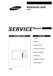
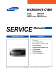
-J04909
REV. 2009-06-01
PREMIUM SUSPENSION KIT
GENERAL
is06083a
Kit Number
54530-10
Models
For model fitment information, see the P&A Retail Catalog or
the Parts and Accessories section of www.harley-davidson.com
(English only). Kit is not compatible with saddle bags P/N
90328-08.
Additional Parts Required
Separate purchase and installation of additional parts or
accessories may be required for proper installation of this kit
on your model motorcycle. See the P&A Retail Catalog or the
Parts and Accessories section of www.harley-davidson.com
(English only) for a list of required parts or accessories for your
model.
Figure 1. Fork Installation Height Measurement.
The rider's safety depends upon the correct installation
of this kit. Use the appropriate service manual procedures.
If the procedure is not within your capabilities or you do
not have the correct tools, have a Harley-Davidson dealer
perform the installation. Improper installation of this kit
could result in death or serious injury. (00333a)
NOTE
This instruction sheet references service manual information.
A service manual for your model motorcycle is required for this
installation and is available from a Harley-Davidson Dealer.
NOTE
If new pinch screws are not readily available, use a wire grinder
wheel to remove all remaining lock patch from original pinch
screws, wash screws in clean solvent and dry thoroughly. Apply
two drops of LOCTITE® 262 to the first 1/4 in. (6.35 mm) of the
end threads.
3.
Install pinch screws to upper and lower fork brackets.
4.
Verify fork tube installation measurement is 0.388-0.468
inch (9.85-11.89 mm).
5.
Tighten pinch screws to 30-35 ft-lbs ( (40.7-47.5 Nm)).
Kit Contents
See Figure 9 and Table 6.
is06209
REMOVAL
Front Fork Assembly
1.
Refer to the XR model section of the service manual and
remove the front forks.
1-1/2 inch
(38.10 mm)
INSTALLATION
Front Fork Assembly
1.
Install front forks from kit to motorcycle according to service manual instructions but do not tighten the fork bracket
pinch screws at this time.
2.
See Figure 1. Measure the distance from the top of upper
fork bracket to top of fork assembly. Both sides must be
exactly the same and measure 0.388-0.468 inch (9.8511.89 mm) above the top fork bracket. Align the adjustment
screws inline with the handlebars (see Figure 5).
Figure 2. Attaching Reflectors to Fork Sliders
-J04909
1 of 6
NOTE
See Figure 2. The top edge of reflector should be 1-1/2 inches
(38.10 mm) below the lower edge of the bottom fork clamp.
6.
Remove the adhesive backing. Place reflector in position
and press reflector firmly into place to activate the
adhesive. Repeat for reflector on opposite fork.
REMOVAL
OEM Rear Shock Absorbers
1.
Refer to the XR model section of the service manual and
remove the rear shock absorbers.
INSTALLATION
Rear Shock Absorbers
1.
See Figure 3. Install the rear shock absorbers according
to service manual instructions. The shocks are installed
with the external gas reservoir to the rear of the shock
absorbers and the thick side of the grommet installed to
the frame rail mounts.
is06142
NOTES
Damping is set at the factory for the average solo rider under
normal riding conditions. The rider may make adjustments to
compensate for individual riding styles and varying road conditions. Evaluating and changing the rebound and compression
damping is a very subjective process with many variables and
should be approached carefully.
The front and rear preload setting will need to be adjusted for
the rider's weight and cargo. This adjustment should be made
before the motorcycle is ridden any distance and after changing
the overall vehicle weight (adding saddlebags, etc.). If the
preload adjustment is correct, and you have the rebound and
compression damping set at the factory recommended points,
the motorcycle should handle and ride properly.
Changes in the load carried requires changes in the preload
setting(s). Carrying less weight than was used for setting up
the suspension requires decreasing the amount of preload.
Increasing the load carried requires adding more preload.
The following tools are needed to make suspension adjustments.
•
5 mm hex key (front fork preload adjustment tool).
•
Spanner wrench with extension handle (shock absorber
preload adjustment).
•
Screw driver (front fork damping adjustment).
1.
Front fork preload adjustment:
a.
See Figure 4 and Table 1. Using the 5 mm hex key,
turn the preload adjuster counterclockwise until it
stops. This is the minimum preload setting.
b.
Turn the preload adjuster clockwise the recommended
amount specified for the rider weight.
is06085
Figure 3. Install Thick Side Of Grommet To Frame Rail
SUSPENSION ADJUSTMENTS
Front Fork Suspension Adjustment
Whenever a wheel is installed and before moving the
motorcycle, pump brakes to build brake system pressure.
Insufficient pressure can adversely affect brake performance, which could result in death or serious injury.
(00284a)
Adjust both forks equally. Improper fork adjustment can
lead to loss of control, which could result in death or serious injury. (00124c)
Figure 4. Fork Preload Adjuster
Compression and rebound adjusting valves may be damaged if too much force is used at either end of the adjustment range. (00237a)
-J04909
2 of 6
Table 1. Recommended Fork Preload Adjustment
RIDER WEIGHT
PRELOAD*
Less than 165 lbs (75 kg)
0-4 turns in
165-195 lbs (75-89 kg)
4-6 turns in
195-225 lbs (89-102 kg)
6-8 turns in
225-255 lbs (102-116 kg)
8-10 turns in
Greater than 255 lbs (116 kg)
More than 10 turns
*Values shown are clockwise turns in from minimum. Rotate
adjuster clockwise to increase preload or counterclockwise
to decrease preload.
Table 2. Recommended Fork Rebound and Compression
Damping Adjustment: XR 1200X
DAMPING*
NOMINAL (FROM MAXIMUM)
Rebound (REB)
3 turns
Compression (COM)
5 turns
*Values shown are counterclockwise turns out from maximum.
Rotate adjuster clockwise to increase damping or counterclockwise to decrease damping.
Shock Absorber Suspension Adjustment
2.
Front rebound damping adjustment:
a.
b.
3.
See Figure 5 and Table 2. Turn the rebound damping
adjuster clockwise until it stops. This is the maximum
rebound damping setting.
Turn the adjuster counterclockwise within the range
of turns specified to the desired setting.
Front fork compression damping adjustment:
a.
See Figure 5 and Table 2. Turn the compression
damping adjuster clockwise until it stops. This is the
maximum compression damping setting.
b.
Turn the adjuster counterclockwise within the range
of turns specified to the desired setting.
Adjust both shock absorbers equally. Improper adjustment
can adversely affect stability and handling, which could
result in death or serious injury. (00036b)
Compression and rebound adjusting valves may be damaged if too much force is used at either end of the adjustment range. (00237a)
NOTE
Do not force adjusters beyond the mechanical stops.
1.
is06086
Shock absorber preload adjustment:
a.
1
2.
Shock absorber compression damping adjustment:
a.
See Figure 6. Using fingers, turn the compression
adjuster (2) clockwise (toward the "H") until it stops.
This is the maximum compression damping setting.
b.
See Table 4. Turn the compression adjuster counterclockwise (toward the "S") the recommended amount.
2
3.
See Figure 6 and Table 3. Using the spanner wrench
turn the adjusting cam (1) to the recommended position as specified in Table 3.
Shock absorber rebound damping:
a.
See Figure 7.Turn the rebound adjuster counterclockwise (toward the "H") until it stops. This is the maximum rebound damping setting.
b.
See Table 4. Turn the rebound adjuster clockwise
(toward the "S") the recommended amount.
1. Rebound damping adjuster
2. Compression damping adjuster
Figure 5. Fork Rebound and Compression Damping
Adjusters
-J04909
3 of 6
is06106
is06087
2
2
1
1
4
1. Minimum preload adjustment
2. Maximum preload adjustment
3
Figure 8. Shock Absorber Preload Adjustment
Table 3. Recommended Rear Shock Preload Adjustment
1.
2.
3.
4.
Preload adjusting cam
Compression damping adjuster
Pressurized gas valve (do not remove cover)
Spanner wrench
Figure 6. Rear Shock Preload and Compression Damping
Adjusters
RIDER WEIGHT
PRELOAD
Less than 165 lb (75 kg)
Position 1
165-195 lb (75-89 kg)
Position 2
195-225 lb (89-102 kg)
Position 3
225-255 lb (102-116 kg)
Position 4
Greater than 255 lb (116 kg)
Position 5
is06105
Table 4. Recommended Rear Shock Rebound and
Compression Damping Adjustment: XR 1200X
DAMPING
NOMINAL
(From Maximum)
Compression (COM)
7 clicks
Rebound (REB)
5 clicks
SUSPENSION TUNING
NOTE
After the preload and damping have been set to the recommended settings, additional adjustments can be made to
enhance the comfort, control and handling characteristics of
the motorcycle.These adjustments may be based on personal
riding style, desired ride quality, and varying road conditions.
Figure 7. Rear Shock Rebound Damping Adjuster
-J04909
1.
Set the front forks and shock absorbers to the recommended settings. Properly inflate the tires.
2.
Determine the ride quality of the motorcycle. Ride the
motorcycle on a familiar road with a variety of bumps and
turns. Ride over different surfaces at varying speeds. If
the suspension is set properly, the vehicle suspension will
feel controlled and comfortable.
3.
See Table 5. Adjust the rebound and compression
damping according to the motorcycle behavior experienced
during the ride.
4.
After adjusting the suspension, ride the motorcycle again
to check for comfort and response.
4 of 6
NOTE
When tuning the suspension, make all adjustments in small
increments. Radical setting changes may overshoot the best
adjustment setting.
MAINTENANCE
Shock Absorbers: These shock absorbers contain pressurized
gas. Visually inspect the shock absorbers while observing the
following precautions.
Table 5. Suspension Damping Adjustment Guidelines:
XR 1200X
MOTORCYCLE BEHAVIOR
SUGGESTED REMEDY
Soft or unsettled feeling around Increase rebound damping
corners or after bumps
Leaping feeling or topping after Increase rebound damping
large bumps
Harsh/sharp feedback over
bumps
Decrease rebound damping
Feels like motorcycle drops down Decrease rebound damping
over chatter bumps
Excessive bottoming through
potholes
Increase compression
damping
Excessive dive when applying
front brake
Increase compression
damping (forks)
Hard feeling or inadequate
absorption over bumps
Decrease compression
damping
Feels excessively stiff or busy
around corners
Decrease compression
damping
-J04909
Shock absorber cannot be serviced. Attempting service
can cause an explosion, which could result in death or
serious injury. (00602d)
•
Do not refill, disassemble, puncture or expose shock to
flames.
•
Replacement and disposal should only be done by an
authorized Harley-Davidson dealer.
Front Forks: The service procedure for these forks are different
than other forks. Refer to the service manual for XR1200X
forks for inspection, maintenance, and service procedures.
5 of 6
SERVICE PARTS
is06108
5
4
3
2
1
7
6
Figure 9. Service Parts: Premium Suspension Kit
Table 6. Service Parts Table
Item
Description (Quantity)
Part Number
1
TORX®
2
Front fork assembly, left
48771-10
3
Front fork assembly, right
48778-10
4
Shock absorber, left
54671-10
5
Shock absorber, right
54700-10
6
Amber reflector, right
69861-07
7
Amber reflector, left
69862-07
-J04909
screw, self tapping, 3/8-16 x 1.5 in. (4)
4352
6 of 6