1
-J06042
REV. 2015-05-22
PREMIUM SUSPENSION FOR XL - TALL
2.
GENERAL
Kit Number
54000076
Install lower shock eye to Right Side (except Japan
models):
a.
Verify bushing (2) is toward vehicle.
b.
Slide lower mounting bolt (7) through washer (8) and
bottom shock eye.
c.
Slide lower mounting bolt through rear fork.
d.
Slide lower mounting bolt through one special washer
(6).
e.
Slide lower mounting bolt through the belt guard.
f.
Slide lower mounting bolt through one special washer
(6).
g.
Apply Loctite 243 (blue) to lower shock bolt. Install
nut (4).
h.
Tighten shock mounting bolt and nut. Tighten to 4550 ft-lbs (61-68 Nm).
Models
For model fitment information, see the P&A Retail Catalog or
the Parts and Accessories section of www.harley-davidson.com
(English only).
Installation Requirements
This kit requires LOCTITE® 243 (blue) for proper installation.
The rider's safety depends upon the correct installation
of this kit. Use the appropriate service manual procedures.
If the procedure is not within your capabilities or you do
not have the correct tools, have a Harley-Davidson dealer
perform the installation. Improper installation of this kit
could result in death or serious injury. (00333a)
NOTE
This instruction sheet references service manual information.
A service manual for your model motorcycle is required for this
installation. One is available from a Harley-Davidson Dealer.
NOTE
The lower right side mounting bolt on Japan models must be
inserted from inside the rear fork (Opposite of what is shown
in Figure 1). Removal and installation of rear wheel is needed
for this step.
3.
Install lower shock eye to Right Side (Japan only models):
Kit Contents
a.
See the service manual. Remove rear wheel.
See Figure 2 and Table 1.
b.
Verify bushing (2) is toward vehicle.
REMOVAL
c.
Slide lower mounting bolt (7) through one special
washer (6).
d.
Slide lower mounting bolt through the belt guard.
e.
Slide lower mounting bolt through one special washer
(6).
f.
Slide lower mounting bolt through rear fork.
g.
Slide lower mounting bolt through bottom shock eye
and washer (8).
h.
Apply Loctite 243 (blue) to lower shock bolt. Install
nut (4).
i.
Tighten shock mounting bolt and nut. Tighten to 4550 ft-lbs (61-68 Nm).
j.
See the service manual. Install rear wheel.
NOTE
When removing shocks, remove and replace one shock at a
time. This method does not require raising and blocking the
rear wheel. To remove both shocks at the same time, place
the motorcycle on a center stand with the rear wheel raised off
the ground.
1.
See the service manual. Remove rear shock absorbers.
Retain the nuts and washers for new shock installation.
INSTALLATION
1.
See Figure 1. Loosely install upper shock mounting bolt
(3) to Both Sides: Position the bushing (2) facing the
inboard side. Install upper shock eye to frame:
-J06042
4.
Remove upper shock bolt. Apply Loctite 243 (blue) to
upper shock bolt.
5.
Slide upper mounting bolt (3) through washer (9) and
upper shock eye.
6.
Slide upper mounting bolt into frame boss.
Many Harley-Davidson® Parts & Accessories are made of plastics and metals which can be recycled.
Please dispose of materials responsibly.
1 of 3
7.
Tighten shock mounting bolt. Tighten to 45-50 ft-lbs (6168 Nm).
8.
Install lower shock mount to Left Side:
SERVICE PARTS
is08619
a.
Verify bushing (2) is toward vehicle.
b.
Slide lower mounting bolt (5) through washer (8) and
bottom shock eye.
c.
Slide lower mounting bolt through rear fork.
d.
Apply Loctite 243 (blue) to lower shock bolt. Install
nut (4).
e.
Tighten shock mounting bolt and nut. Tighten to 4550 ft-lbs (61-68 Nm).
3
2
2
1
5
6
9.
4
Remove upper shock bolt. Apply Loctite 243 (blue) to
upper shock bolt.
10. Slide upper mounting bolt (3) through washer (9) and
upper shock eye.
Figure 2. Service Parts: XL Rear Shock Kit
11. Slide upper mounting bolt into frame boss.
12. Tighten shock mounting bolt. Tighten to 45-50 ft-lbs (6168 Nm).
Table 1. Service Parts
Item
is08621
5
9
2 Screw, button head, Torx, 1/2 x 2-1/2 (2) 10200392
3 Shock absorber (2)
2
2
1
9
Part Number
1 Spanner wrench
8
3
Description (Quantity)
3
14900080
54000086
4 Screw, button head, Torx, 1/2 x 2-7/8 (1) 10200445
5 Washer, special (2)
10600039
6 Screw, button head, Torx, 1/2 x 2-5/8 (1) 10200412
4
2
6
1
8
4
7
1.
2.
3.
4.
5.
6.
7.
8.
9.
Shock absorber
Bushing
Screw, button head, torx, 1/2 x 2-1/2 (2)
Nuts (2)
Screw, button head, torx, 1/2 x 2-5/8
Washer, special (2)
Screw, button head, torx, 1/2 x 2-7/8
Washer, 1 in (2)
Washer, 7/8 in (2)
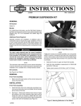
Figure 1. Rear Shock Absorber Installation
-J06042
2 of 3
SHOCK ABSORBER ADJUSTMENT
Adjust both shock absorbers equally. Improper adjustment
can adversely affect stability and handling, which could
result in death or serious injury. (00036b)
1.
See Table 2. Determine desired upper locking ring location
for the total weight of rider, passenger cargo and
accessories.
2.
Clean the adjuster threads.
3.
See Figure 3. Use the spanner wrench to turn the upper
locking ring counterclockwise (1) to unlock the ring:
NOTE
Count down from the top of the shock to locate the recommended preload dot.
NOTE
The locknut is not tight on new shock. The adjustment must
be completed and the adjuster nut locked before vehicle
operation.
NOTE
To prevent damage to the adjustment and locking rings, do
not use any other wrench than the one supplied with this kit.
Avoid shock damage. Make sure shock threads are clean
and free of debris before loosening or tightening shock
adjusting nuts. 00646b
4.
Use the spanner wrench to turn (2) the lower adjustment
ring below the recommended dot.
5.
Rotate the upper locking ring to align with the recommended preload dot (3).
6.
Cover one-half the recommended preload dot (4) with the
upper locking ring.
7.
Use the wrench to hand tighten the lower adjustment ring
against the locking ring (5)
8.
Repeat Shock Absorber Adjustment steps on other side.
9.
Verify that both shocks are adjusted evenly.
is08620a
4
2
3
1
5
1. Loosen locking ring
2. Turn adjustment ring below recommended dot
3. Rotate locking ring to dot
4. Align locking ring to dot
5. Tighten adjustment ring
Figure 3. Preload Adjustment
PRELOAD TABLES
Table 2. Tall Travel Shocks Preload
WEIGHT OF PASSENGER, CARGO AND ACCESSORIES
lb
0 18
kg
0 8.2 16.3 24.5 32.7 40.8 49.0 57.2 65.3 73.5 81.6 89.8 98.0 106.1
36
54
72
90
RIDER WEIGHT
-J06042
108 126 144 162 180 198 216
234
PRELOAD DOT
lb
kg
116-141
52.6-64.0
1
2
3
4
5
6
7
142-167
64.4-75.7
2
3
4
5
6
7
168-193
76.2-87.5
3
4
5
6
7
8
194-219
88.0-99.3
4
5
6
7
8
9
8
9
10
11
11
12
13
8
9
10
11
11
12
13
-
9
10
11
11
12
13
-
-
10
11
11
12
13
-
-
-
3 of 3